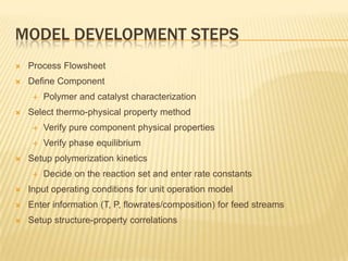
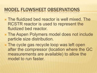
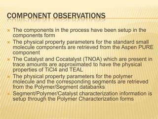
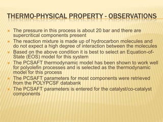
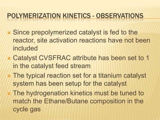
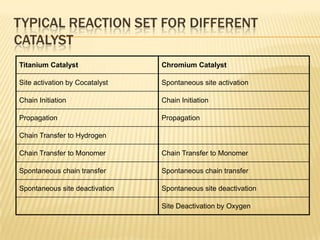
ASPEN POLYMER
PROJECT IMPLEMENTATION
OVERVIEW


             this presentation slide is intended for internal discussion only
                       ASPEN Polymer Project Implementation Overview
MODEL DEVELOPMENT STEPS
   Process Flowsheet
   Define Component
        Polymer and catalyst characterization
   Select thermo-physical property method
        Verify pure component physical properties
        Verify phase equilibrium
   Setup polymerization kinetics
        Decide on the reaction set and enter rate constants
   Input operating conditions for unit operation model
   Enter information (T, P, flowrates/composition) for feed streams
   Setup structure-property correlations
MODEL FLOWSHEET OBSERVATIONS
 The fluidized bed reactor is well mixed. The
  RCSTR reactor is used to represent the
  fluidized bed reactor.
 The Aspen Polymers model does not include
  particle size distribution.
 The cycle gas recycle loop was left open
  after the compressor (location where the GC
  measurements are available) to allow the
  model to run faster.
COMPONENT OBSERVATIONS
   The components in the process have been setup in the
    components form
   The physical property parameters for the standard small
    molecule components are retrieved from the Aspen PURE
    component
   The Catalyst and Cocatalyst (TNOA) which are present in
    trace amounts are approximated to have the physical
    properties of TiCl4 and TEAL
   The physical property parameters for the polymer
    molecule and the corresponding segments are retrieved
    from the Polymer/Segment databanks
   Segment/Polymer/Catalyst characterization information is
    setup through the Polymer Characterization forms
THERMO-PHYSICAL PROPERTY - OBSERVATIONS
   The pressure in this process is about 20 bar and there are
    supercritical components present
   The reaction mixture is made up of hydrocarbon molecules and
    do not expect a high degree of interaction between the molecules
   Based on the above condition it is best to select an Equation-of-
    State (EOS) model for this system
   The PCSAFT thermodynamic model has been shown to work well
    for polyolefin processes and is selected as the thermodynamic
    model for this process
   The PCSAFT parameters for most components were retrieved
    from the POLYPCSF databank
   The PCSAFT parameters is entered for the catalyst/co-catalyst
    components
POLYMERIZATION KINETICS - OBSERVATIONS

 Since prepolymerized catalyst is fed to the
  reactor, site activation reactions have not been
  included
 Catalyst CVSFRAC attribute has been set to 1
  in the catalyst feed stream
 The typical reaction set for a titanium catalyst
  system has been setup for the catalyst
 The hydrogenation kinetics must be tuned to
  match the Ethane/Butane composition in the
  cycle gas
TYPICAL REACTION SET FOR DIFFERENT
CATALYST
Titanium Catalyst               Chromium Catalyst

Site activation by Cocatalyst   Spontaneous site activation

Chain Initiation                Chain Initiation

Propagation                     Propagation

Chain Transfer to Hydrogen

Chain Transfer to Monomer       Chain Transfer to Monomer

Spontaneous chain transfer      Spontaneous chain transfer

Spontaneous site deactivation   Spontaneous site deactivation

                                Site Deactivation by Oxygen
OPERATING CONDITIONS FOR UNIT OPERATION
MODEL
   The different unit operation block in the flowsheet require some
    operation conditions.
   Typical reactor block operating conditions
       Temperature,
       Pressure
       Total volume
       Phase volume
       Reaction sets
   Heat/Cooler Block
       Outlet temperature
       Outlet Pressure or pressure drop
   Compresssor Block
       Discharge pressure or pressure increase
OPERATING CONDITIONS FOR FEED STREAMS

   Typical inputs for the feed streams include
     Temperature

     Pressure

     Total flow rate and composition or component
      flow rates.
STRUCTURE – PROPERTY CORRELATIONS FOR
GAS PHASE HDPE
 Literature
         Correlations for HDPE with 1-Butene
  comonomer
    MI = (111525/Mw)3.472
        = 0.966 – 2.386E-2 * (100*SFRAC)0.514

McAuley, K.B., J.F. MacGregor and A.E. Hamielec, AIChE J., Vol 36, No 6,
 1990
FIT/VALIDATE STRUCTURE – PROPERTY
CORRELATIONS
   Correlation fitted to plant data
       MI = A * exp(- B * MWN)
              - C * Ln(MWW) + D
    Need molecular structure (Mn, Mw,
    copolymer composition) and product property
    (MI, density) data for several grades to
    develop these correlations
DATA COLLECTION

 The data requirements list was generated
  from the base model.
 The list was reviewed and the tag names
  added for the plant data
 A excel template has been setup to aid the
  data collection
THANK YOU

Aspen Polymer Project Implementation Overview

  • 1.
    ASPEN POLYMER PROJECT IMPLEMENTATION OVERVIEW this presentation slide is intended for internal discussion only ASPEN Polymer Project Implementation Overview
  • 2.
    MODEL DEVELOPMENT STEPS  Process Flowsheet  Define Component  Polymer and catalyst characterization  Select thermo-physical property method  Verify pure component physical properties  Verify phase equilibrium  Setup polymerization kinetics  Decide on the reaction set and enter rate constants  Input operating conditions for unit operation model  Enter information (T, P, flowrates/composition) for feed streams  Setup structure-property correlations
  • 3.
    MODEL FLOWSHEET OBSERVATIONS The fluidized bed reactor is well mixed. The RCSTR reactor is used to represent the fluidized bed reactor.  The Aspen Polymers model does not include particle size distribution.  The cycle gas recycle loop was left open after the compressor (location where the GC measurements are available) to allow the model to run faster.
  • 4.
    COMPONENT OBSERVATIONS  The components in the process have been setup in the components form  The physical property parameters for the standard small molecule components are retrieved from the Aspen PURE component  The Catalyst and Cocatalyst (TNOA) which are present in trace amounts are approximated to have the physical properties of TiCl4 and TEAL  The physical property parameters for the polymer molecule and the corresponding segments are retrieved from the Polymer/Segment databanks  Segment/Polymer/Catalyst characterization information is setup through the Polymer Characterization forms
  • 5.
    THERMO-PHYSICAL PROPERTY -OBSERVATIONS  The pressure in this process is about 20 bar and there are supercritical components present  The reaction mixture is made up of hydrocarbon molecules and do not expect a high degree of interaction between the molecules  Based on the above condition it is best to select an Equation-of- State (EOS) model for this system  The PCSAFT thermodynamic model has been shown to work well for polyolefin processes and is selected as the thermodynamic model for this process  The PCSAFT parameters for most components were retrieved from the POLYPCSF databank  The PCSAFT parameters is entered for the catalyst/co-catalyst components
  • 6.
    POLYMERIZATION KINETICS -OBSERVATIONS  Since prepolymerized catalyst is fed to the reactor, site activation reactions have not been included  Catalyst CVSFRAC attribute has been set to 1 in the catalyst feed stream  The typical reaction set for a titanium catalyst system has been setup for the catalyst  The hydrogenation kinetics must be tuned to match the Ethane/Butane composition in the cycle gas
  • 7.
    TYPICAL REACTION SETFOR DIFFERENT CATALYST Titanium Catalyst Chromium Catalyst Site activation by Cocatalyst Spontaneous site activation Chain Initiation Chain Initiation Propagation Propagation Chain Transfer to Hydrogen Chain Transfer to Monomer Chain Transfer to Monomer Spontaneous chain transfer Spontaneous chain transfer Spontaneous site deactivation Spontaneous site deactivation Site Deactivation by Oxygen
  • 8.
    OPERATING CONDITIONS FORUNIT OPERATION MODEL  The different unit operation block in the flowsheet require some operation conditions.  Typical reactor block operating conditions  Temperature,  Pressure  Total volume  Phase volume  Reaction sets  Heat/Cooler Block  Outlet temperature  Outlet Pressure or pressure drop  Compresssor Block  Discharge pressure or pressure increase
  • 9.
    OPERATING CONDITIONS FORFEED STREAMS  Typical inputs for the feed streams include  Temperature  Pressure  Total flow rate and composition or component flow rates.
  • 10.
    STRUCTURE – PROPERTYCORRELATIONS FOR GAS PHASE HDPE  Literature Correlations for HDPE with 1-Butene comonomer MI = (111525/Mw)3.472 = 0.966 – 2.386E-2 * (100*SFRAC)0.514 McAuley, K.B., J.F. MacGregor and A.E. Hamielec, AIChE J., Vol 36, No 6, 1990
  • 11.
    FIT/VALIDATE STRUCTURE –PROPERTY CORRELATIONS  Correlation fitted to plant data MI = A * exp(- B * MWN) - C * Ln(MWW) + D Need molecular structure (Mn, Mw, copolymer composition) and product property (MI, density) data for several grades to develop these correlations
  • 12.
    DATA COLLECTION  Thedata requirements list was generated from the base model.  The list was reviewed and the tag names added for the plant data  A excel template has been setup to aid the data collection
  • 13.