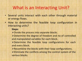
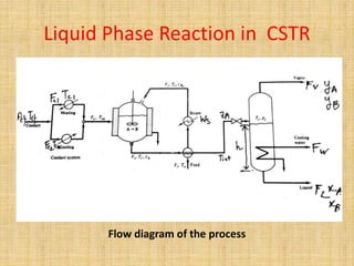
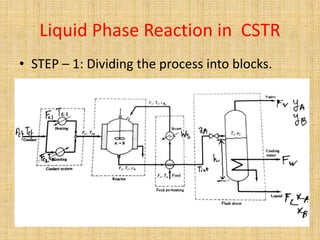
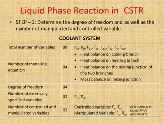
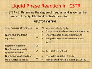
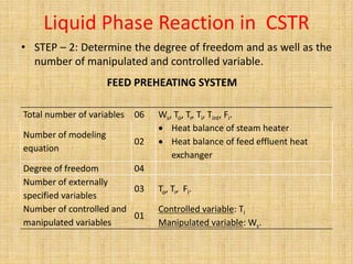
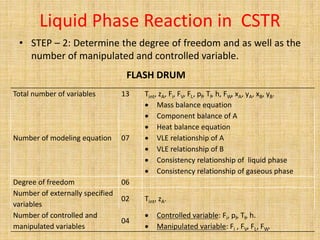
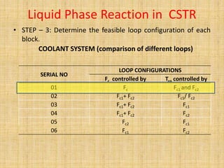
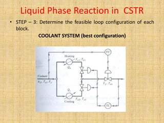
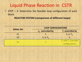
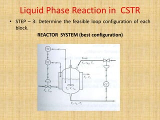
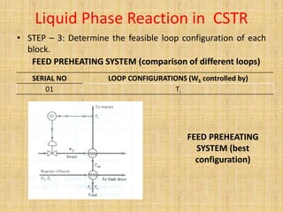
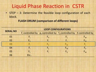
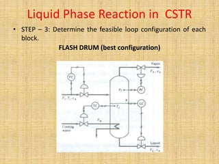
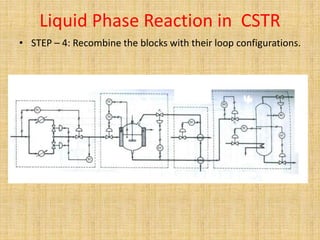
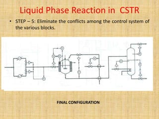
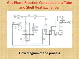
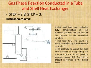
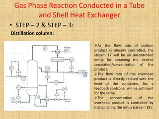
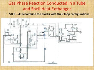
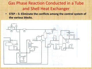
Control Loop Configuration of
Interacting Units
Dr. S. Jana
Department of Chemical Engineering
Banasthali University
What is an Interacting Unit?
• Several units interact with each other through material
or energy flows.
• How to determine the feasible loop configuration in
interacting units?
Steps:
Divide the process into separate blocks.
Determine the degree of freedom and no of controlled
and manipulated variables for each block.
Determine the feasible loop configurations for each
and every block.
Recombine the blocks with their loop configurations.
Eliminate the conflicts among the control system of the
various blocks.
We will study …… …..
 An exothermic liquid phase reaction conducted in a
CSTR and separated/purified in a flash drum.
 An exothermic gas phase reaction conducted in a
tube and shell heat exchanger and
separated/purified in a combined system of flash
drum and distillation column.
The control configuration of:
Liquid Phase Reaction in CSTR
Flow diagram of the process
• Objectives/Operational Goals:
Liquid Phase Reaction in CSTR
To keep the conversion in the reactor at its highest
permissible limit.
To maintain a constant production rate.
To achieve constant composition in the liquid product of
the flash drum.
• STEP – 1: Dividing the process into blocks.
Liquid Phase Reaction in CSTR
• STEP – 2: Determine the degree of freedom and as well as the
number of manipulated and controlled variable.
Total number of variables 08 Pcf, Tcf, Fc1, Tc1, Fc2, Tc2, Fc, Tco.
Number of modeling
equation
04
 Heat balance on cooling branch
 Heat balance on heating branch
 Heat balance on the mixing junction of
the two branches
 Mass balance on mixing junction
Degree of freedom 04
Number of externally
specified variables
02 Pcf, Tcf,
Number of controlled and
manipulated variables
02
Controlled Variable: Fc, Tco
Manipulated Variable: Fc, Tco
COOLANT SYSTEM
DETERMINED BY
QUALITATIVE
ARGUMENTS
Liquid Phase Reaction in CSTR
• STEP – 2: Determine the degree of freedom and as well as the
number of manipulated and controlled variable.
REACTOR SYSTEM
Total number of variables 09 V, Tr, cA, cAi, Ti, Fi, Fc, Tc, Tco.
Number of modeling
equation
03
 Component A balance around the reactor
 Energy balance on reacting mixture
 Energy balance on the coolant in the
jacket
Degree of freedom 06
Number of externally
specified variables
04 cAi, Ti, Fi and (Fc, OR Tco)
Number of controlled and
manipulated variables
02
 Controlled variable: Tr and cA.
 Manipulated variable: Fi and (Fc, OR Tco)
Liquid Phase Reaction in CSTR
• STEP – 2: Determine the degree of freedom and as well as the
number of manipulated and controlled variable.
FEED PREHEATING SYSTEM
Total number of variables 06 Ws, To, Tr, Ti, Tint, Fi.
Number of modeling
equation
02
 Heat balance of steam heater
 Heat balance of feed effluent heat
exchanger
Degree of freedom 04
Number of externally
specified variables
03 To, Tr, Fi.
Number of controlled and
manipulated variables
01
Controlled variable: Ti
Manipulated variable: Ws.
Liquid Phase Reaction in CSTR
• STEP – 2: Determine the degree of freedom and as well as the
number of manipulated and controlled variable.
FLASH DRUM
Total number of variables 13 Tint, zA, Fi, FV, FL, pf, Tf, h, FW, xA, yA, xB, yB.
Number of modeling equation 07
 Mass balance equation
 Component balance of A
 Heat balance equation
 VLE relationship of A
 VLE relationship of B
 Consistency relationship of liquid phase
 Consistency relationship of gaseous phase
Degree of freedom 06
Number of externally specified
variables
02 Tint, zA.
Number of controlled and
manipulated variables
04
 Controlled variable: Fi, pf, Tf, h.
 Manipulated variable: Fi , FV, FL, FW.
Liquid Phase Reaction in CSTR
• STEP – 3: Determine the feasible loop configuration of each
block.
COOLANT SYSTEM (comparison of different loops)
SERIAL NO
LOOP CONFIGURATIONS
Fc controlled by Tco controlled by
01 Fc Fc1 and Fc2
02 Fc1+ Fc2 Fc1/ Fc2
03 Fc1+ Fc2 Fc1
04 Fc1+ Fc2 Fc2
05 Fc2 Fc1
06 Fc1 Fc2
Liquid Phase Reaction in CSTR
• STEP – 3: Determine the feasible loop configuration of each
block.
COOLANT SYSTEM (best configuration)
Liquid Phase Reaction in CSTR
• STEP – 3: Determine the feasible loop configuration of each
block.
REACTOR SYSTEM (comparison of different loops)
SERIAL NO
LOOP CONFIGURATIONS
cA controlled by Tr controlled by
01 Fi Fc or Tco
02 Fc or Tco Fi
03 Fi
Fc with Tc (cascade
configuration)
Liquid Phase Reaction in CSTR
• STEP – 3: Determine the feasible loop configuration of each
block.
REACTOR SYSTEM (best configuration)
Liquid Phase Reaction in CSTR
• STEP – 3: Determine the feasible loop configuration of each
block.
FEED PREHEATING SYSTEM (comparison of different loops)
SERIAL NO LOOP CONFIGURATIONS (WS controlled by)
01 Ti
FEED PREHEATING
SYSTEM (best
configuration)
Liquid Phase Reaction in CSTR
• STEP – 3: Determine the feasible loop configuration of each
block.
FLASH DRUM (comparison of different loops)
SERIAL NO
LOOP CONFIGURATIONS
Fi controlled by pf controlled by Tf controlled by h controlled by
01 Fi FV FL FW
02 FV Fi FL FW
03 Fi FV FW FL
04 Fi FL FW FV
05 FL Fi FV FW
06 Etc..
Liquid Phase Reaction in CSTR
• STEP – 3: Determine the feasible loop configuration of each
block.
FLASH DRUM (best configuration)
Liquid Phase Reaction in CSTR
• STEP – 4: Recombine the blocks with their loop configurations.
Liquid Phase Reaction in CSTR
• STEP – 5: Eliminate the conflicts among the control system of
the various blocks.
FINAL CONFIGURATION
Gas Phase Reaction Conducted in a Tube
and Shell Heat Exchanger
Flow diagram of the process
Gas Phase Reaction Conducted in a Tube
and Shell Heat Exchanger
• STEP – 1: Dividing the process into blocks.
Gas Phase Reaction Conducted in a Tube
and Shell Heat Exchanger
• STEP – 2 & STEP – 3:
Due to the complicacy of the system, it is analyzed in an
qualitative manner. In spite of going through the process used
in the last example we will try to analyze the configurations
according to the experience and understanding of the system.
Lets try to analyze each and every block separately for finding
the best loop configuration for each of them.
Gas Phase Reaction Conducted in a Tube
and Shell Heat Exchanger
• STEP – 2 & STEP – 3:
Compressors for fresh feed gas A (C-1) and recycled gas A (C-2)
from the flash drum:
Simple feedback pressure controller would be sufficient.
The pressure measurement and manipulation have to be done at the outlet of
the compressor.
Recycle of the feed gas to the inlet line is necessary as the reactant cannot be
wasted.
Gas Phase Reaction Conducted in a Tube
and Shell Heat Exchanger
• STEP – 2 & STEP – 3:
Mixing drum for the fresh feed B and the recycled stream from
the bottom of the distillation column:
Inlet and outlet flow could be controlled by
feed-forward controller because the
mathematical model of the mixing drum is not
much complicated.
The level of the drum is another important
parameter to be controlled. It can be controlled
by the flow rate of feed B (stream 2) or by the
recycled stream from the distillation column
(stream 3).
Controlling stream 2 is a better choice
because change in the flow rate of stream 3
could affect the performance of the distillation
column.
Gas Phase Reaction Conducted in a Tube
and Shell Heat Exchanger
• STEP – 2 & STEP – 3:
Feed vaporizing and preheating:
The feed flow rate of stream 8 or 9 and
the temperature of stream 9 are the
controlled output.
The feed flow rate could be controlled
by a feed-forward controller.
Only one manipulated variable (steam
flow rate) is available for controlling the
temperature of stream 9.
Gas Phase Reaction Conducted in a Tube
and Shell Heat Exchanger
• STEP – 2 & STEP – 3:
Reactor system:
The inlet reactant flow rate and the
temperature of the reactor are the controlled
variable.
The flow rate could be controlled by the
feed-forward controller.
The temperature of the reactor can only
controlled by manipulating the flow rate of
coolant only.
Gas Phase Reaction Conducted in a Tube
and Shell Heat Exchanger
• STEP – 2 & STEP – 3:
Flash drum system:
The inlet stream flow rate and
temperature are the obvious controlled
parameter.
Another two important controlled
parameters are the pressure and the
level of the flash drum.
The inlet flow rate (stream 11) can be
controlled by a feed-forward controller.
Temperature of the inlet stream is
controlled by the coolant water by
feedback controller. Using of a feed-
forward controller could be difficult
because the temperature of the cooling
water is unknown.
Gas Phase Reaction Conducted in a Tube
and Shell Heat Exchanger
• STEP – 2 & STEP – 3:
Flash drum system:
The best way to control the
pressure of the flash drum is
manipulating the flow rate of top
gaseous product.
The level of the flash drum is
controlled by the outlet flow rate of
the liquid (stream 15).
Gas Phase Reaction Conducted in a Tube
and Shell Heat Exchanger
• STEP – 2 & STEP – 3:
Distillation column:
Inlet feed flow rate, re-boiler
duty, concentration of the
overhead product and the level of
the column are the controlled
variables.
Inlet feed flow rate could be
easily controlled by a feed-forward
controller.
The best way to control the level
of the column is manipulating the
flow rate of the bottom product
(contains mainly of B). The bottom
product is recycled to the mixing
drum.
Gas Phase Reaction Conducted in a Tube
and Shell Heat Exchanger
• STEP – 2 & STEP – 3:
Distillation column:
As the flow rate of bottom
product is already controlled, the
stream 17 will be an uncontrolled
entity for obtaining the desired
separation/concentration of the
product.
The flow rate of the overhead
product is directly related with the
level of the condenser. So, a
feedback controller will be sufficient
for the same.
The concentration of the
overhead product is controlled by
manipulating the reflux (stream 18).
Gas Phase Reaction Conducted in a Tube
and Shell Heat Exchanger
• STEP – 4: Recombine the blocks with their loop configurations
Gas Phase Reaction Conducted in a Tube
and Shell Heat Exchanger
• STEP – 5: Eliminate the conflicts among the control system of
the various blocks.
REFERENCE:
Chemical Process Control -- An Introduction to Theory
and Practices By George Stephanopoulos, PHI Learning
Pvt. Ltd.
Control loop configuration of interacting units

Control loop configuration of interacting units

  • 1.
    Control Loop Configurationof Interacting Units Dr. S. Jana Department of Chemical Engineering Banasthali University
  • 2.
    What is anInteracting Unit? • Several units interact with each other through material or energy flows. • How to determine the feasible loop configuration in interacting units? Steps: Divide the process into separate blocks. Determine the degree of freedom and no of controlled and manipulated variables for each block. Determine the feasible loop configurations for each and every block. Recombine the blocks with their loop configurations. Eliminate the conflicts among the control system of the various blocks.
  • 3.
    We will study…… …..  An exothermic liquid phase reaction conducted in a CSTR and separated/purified in a flash drum.  An exothermic gas phase reaction conducted in a tube and shell heat exchanger and separated/purified in a combined system of flash drum and distillation column. The control configuration of:
  • 4.
    Liquid Phase Reactionin CSTR Flow diagram of the process
  • 5.
    • Objectives/Operational Goals: LiquidPhase Reaction in CSTR To keep the conversion in the reactor at its highest permissible limit. To maintain a constant production rate. To achieve constant composition in the liquid product of the flash drum.
  • 6.
    • STEP –1: Dividing the process into blocks. Liquid Phase Reaction in CSTR
  • 7.
    Liquid Phase Reactionin CSTR • STEP – 2: Determine the degree of freedom and as well as the number of manipulated and controlled variable. Total number of variables 08 Pcf, Tcf, Fc1, Tc1, Fc2, Tc2, Fc, Tco. Number of modeling equation 04  Heat balance on cooling branch  Heat balance on heating branch  Heat balance on the mixing junction of the two branches  Mass balance on mixing junction Degree of freedom 04 Number of externally specified variables 02 Pcf, Tcf, Number of controlled and manipulated variables 02 Controlled Variable: Fc, Tco Manipulated Variable: Fc, Tco COOLANT SYSTEM DETERMINED BY QUALITATIVE ARGUMENTS
  • 8.
    Liquid Phase Reactionin CSTR • STEP – 2: Determine the degree of freedom and as well as the number of manipulated and controlled variable. REACTOR SYSTEM Total number of variables 09 V, Tr, cA, cAi, Ti, Fi, Fc, Tc, Tco. Number of modeling equation 03  Component A balance around the reactor  Energy balance on reacting mixture  Energy balance on the coolant in the jacket Degree of freedom 06 Number of externally specified variables 04 cAi, Ti, Fi and (Fc, OR Tco) Number of controlled and manipulated variables 02  Controlled variable: Tr and cA.  Manipulated variable: Fi and (Fc, OR Tco)
  • 9.
    Liquid Phase Reactionin CSTR • STEP – 2: Determine the degree of freedom and as well as the number of manipulated and controlled variable. FEED PREHEATING SYSTEM Total number of variables 06 Ws, To, Tr, Ti, Tint, Fi. Number of modeling equation 02  Heat balance of steam heater  Heat balance of feed effluent heat exchanger Degree of freedom 04 Number of externally specified variables 03 To, Tr, Fi. Number of controlled and manipulated variables 01 Controlled variable: Ti Manipulated variable: Ws.
  • 10.
    Liquid Phase Reactionin CSTR • STEP – 2: Determine the degree of freedom and as well as the number of manipulated and controlled variable. FLASH DRUM Total number of variables 13 Tint, zA, Fi, FV, FL, pf, Tf, h, FW, xA, yA, xB, yB. Number of modeling equation 07  Mass balance equation  Component balance of A  Heat balance equation  VLE relationship of A  VLE relationship of B  Consistency relationship of liquid phase  Consistency relationship of gaseous phase Degree of freedom 06 Number of externally specified variables 02 Tint, zA. Number of controlled and manipulated variables 04  Controlled variable: Fi, pf, Tf, h.  Manipulated variable: Fi , FV, FL, FW.
  • 11.
    Liquid Phase Reactionin CSTR • STEP – 3: Determine the feasible loop configuration of each block. COOLANT SYSTEM (comparison of different loops) SERIAL NO LOOP CONFIGURATIONS Fc controlled by Tco controlled by 01 Fc Fc1 and Fc2 02 Fc1+ Fc2 Fc1/ Fc2 03 Fc1+ Fc2 Fc1 04 Fc1+ Fc2 Fc2 05 Fc2 Fc1 06 Fc1 Fc2
  • 12.
    Liquid Phase Reactionin CSTR • STEP – 3: Determine the feasible loop configuration of each block. COOLANT SYSTEM (best configuration)
  • 13.
    Liquid Phase Reactionin CSTR • STEP – 3: Determine the feasible loop configuration of each block. REACTOR SYSTEM (comparison of different loops) SERIAL NO LOOP CONFIGURATIONS cA controlled by Tr controlled by 01 Fi Fc or Tco 02 Fc or Tco Fi 03 Fi Fc with Tc (cascade configuration)
  • 14.
    Liquid Phase Reactionin CSTR • STEP – 3: Determine the feasible loop configuration of each block. REACTOR SYSTEM (best configuration)
  • 15.
    Liquid Phase Reactionin CSTR • STEP – 3: Determine the feasible loop configuration of each block. FEED PREHEATING SYSTEM (comparison of different loops) SERIAL NO LOOP CONFIGURATIONS (WS controlled by) 01 Ti FEED PREHEATING SYSTEM (best configuration)
  • 16.
    Liquid Phase Reactionin CSTR • STEP – 3: Determine the feasible loop configuration of each block. FLASH DRUM (comparison of different loops) SERIAL NO LOOP CONFIGURATIONS Fi controlled by pf controlled by Tf controlled by h controlled by 01 Fi FV FL FW 02 FV Fi FL FW 03 Fi FV FW FL 04 Fi FL FW FV 05 FL Fi FV FW 06 Etc..
  • 17.
    Liquid Phase Reactionin CSTR • STEP – 3: Determine the feasible loop configuration of each block. FLASH DRUM (best configuration)
  • 18.
    Liquid Phase Reactionin CSTR • STEP – 4: Recombine the blocks with their loop configurations.
  • 19.
    Liquid Phase Reactionin CSTR • STEP – 5: Eliminate the conflicts among the control system of the various blocks. FINAL CONFIGURATION
  • 20.
    Gas Phase ReactionConducted in a Tube and Shell Heat Exchanger Flow diagram of the process
  • 21.
    Gas Phase ReactionConducted in a Tube and Shell Heat Exchanger • STEP – 1: Dividing the process into blocks.
  • 22.
    Gas Phase ReactionConducted in a Tube and Shell Heat Exchanger • STEP – 2 & STEP – 3: Due to the complicacy of the system, it is analyzed in an qualitative manner. In spite of going through the process used in the last example we will try to analyze the configurations according to the experience and understanding of the system. Lets try to analyze each and every block separately for finding the best loop configuration for each of them.
  • 23.
    Gas Phase ReactionConducted in a Tube and Shell Heat Exchanger • STEP – 2 & STEP – 3: Compressors for fresh feed gas A (C-1) and recycled gas A (C-2) from the flash drum: Simple feedback pressure controller would be sufficient. The pressure measurement and manipulation have to be done at the outlet of the compressor. Recycle of the feed gas to the inlet line is necessary as the reactant cannot be wasted.
  • 24.
    Gas Phase ReactionConducted in a Tube and Shell Heat Exchanger • STEP – 2 & STEP – 3: Mixing drum for the fresh feed B and the recycled stream from the bottom of the distillation column: Inlet and outlet flow could be controlled by feed-forward controller because the mathematical model of the mixing drum is not much complicated. The level of the drum is another important parameter to be controlled. It can be controlled by the flow rate of feed B (stream 2) or by the recycled stream from the distillation column (stream 3). Controlling stream 2 is a better choice because change in the flow rate of stream 3 could affect the performance of the distillation column.
  • 25.
    Gas Phase ReactionConducted in a Tube and Shell Heat Exchanger • STEP – 2 & STEP – 3: Feed vaporizing and preheating: The feed flow rate of stream 8 or 9 and the temperature of stream 9 are the controlled output. The feed flow rate could be controlled by a feed-forward controller. Only one manipulated variable (steam flow rate) is available for controlling the temperature of stream 9.
  • 26.
    Gas Phase ReactionConducted in a Tube and Shell Heat Exchanger • STEP – 2 & STEP – 3: Reactor system: The inlet reactant flow rate and the temperature of the reactor are the controlled variable. The flow rate could be controlled by the feed-forward controller. The temperature of the reactor can only controlled by manipulating the flow rate of coolant only.
  • 27.
    Gas Phase ReactionConducted in a Tube and Shell Heat Exchanger • STEP – 2 & STEP – 3: Flash drum system: The inlet stream flow rate and temperature are the obvious controlled parameter. Another two important controlled parameters are the pressure and the level of the flash drum. The inlet flow rate (stream 11) can be controlled by a feed-forward controller. Temperature of the inlet stream is controlled by the coolant water by feedback controller. Using of a feed- forward controller could be difficult because the temperature of the cooling water is unknown.
  • 28.
    Gas Phase ReactionConducted in a Tube and Shell Heat Exchanger • STEP – 2 & STEP – 3: Flash drum system: The best way to control the pressure of the flash drum is manipulating the flow rate of top gaseous product. The level of the flash drum is controlled by the outlet flow rate of the liquid (stream 15).
  • 29.
    Gas Phase ReactionConducted in a Tube and Shell Heat Exchanger • STEP – 2 & STEP – 3: Distillation column: Inlet feed flow rate, re-boiler duty, concentration of the overhead product and the level of the column are the controlled variables. Inlet feed flow rate could be easily controlled by a feed-forward controller. The best way to control the level of the column is manipulating the flow rate of the bottom product (contains mainly of B). The bottom product is recycled to the mixing drum.
  • 30.
    Gas Phase ReactionConducted in a Tube and Shell Heat Exchanger • STEP – 2 & STEP – 3: Distillation column: As the flow rate of bottom product is already controlled, the stream 17 will be an uncontrolled entity for obtaining the desired separation/concentration of the product. The flow rate of the overhead product is directly related with the level of the condenser. So, a feedback controller will be sufficient for the same. The concentration of the overhead product is controlled by manipulating the reflux (stream 18).
  • 31.
    Gas Phase ReactionConducted in a Tube and Shell Heat Exchanger • STEP – 4: Recombine the blocks with their loop configurations
  • 32.
    Gas Phase ReactionConducted in a Tube and Shell Heat Exchanger • STEP – 5: Eliminate the conflicts among the control system of the various blocks.
  • 33.
    REFERENCE: Chemical Process Control-- An Introduction to Theory and Practices By George Stephanopoulos, PHI Learning Pvt. Ltd.