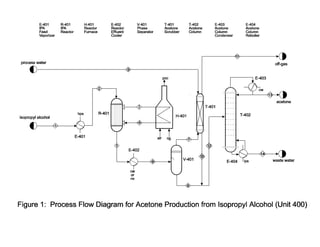
This document provides details for a design project involving the production of acetone. Students are tasked with designing a process to produce 15,000 metric tons per year of acetone via the reaction of isopropanol. The document outlines the process details including feed streams, equipment, costs, and economic analysis. It also specifies the deliverables which include a written report with process flow diagram and stream table, as well as an oral presentation.

![6
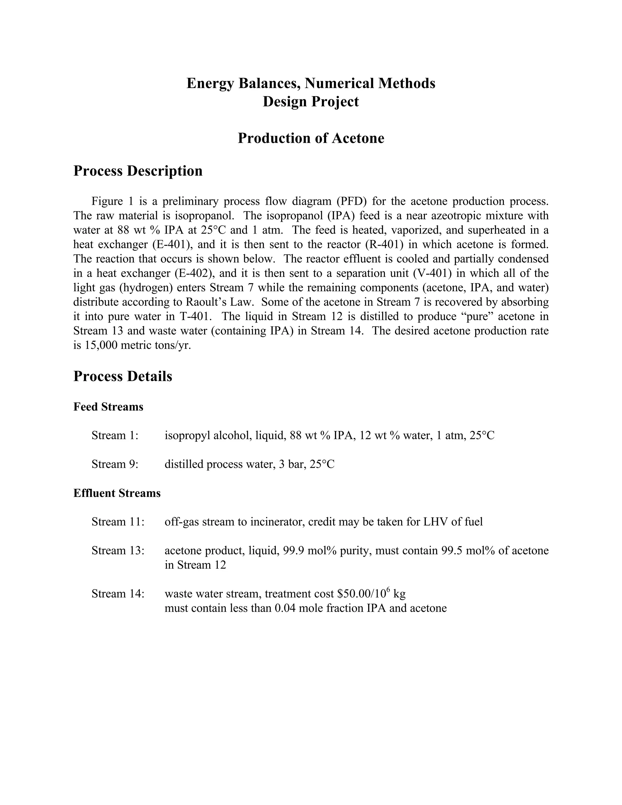
Utility Costs
Low-Pressure Steam (446 kPa, saturated) $5.00/1000 kg
Medium-Pressure Steam (1135 kPa, saturated) $7.31/1000 kg
High-Pressure Steam (4237 kPa, saturated) $8.65/1000 kg
Natural Gas or Fuel Gas (446 kPa, 25°C) $3.00/GJ
Electricity $0.05/kW h
Boiler Feed Water (at 549 kPa, 90°C) $2.54/1000 kg
Cooling Water $0.16/GJ
available at 516 kPa and 30°C
return pressure ≥ 308 kPa
return temperature should be no more than 15°C above the inlet temperature
Refrigerated Water $1.60/GJ
available at 516 kPa and 10°C
return pressure ≥ 308 kPa
return temperature is no higher than 20°C
Process Water $0.04/1000 kg
available at 300 kPa and 25°C
Data
Use data from Reference [1] or from any handbook (such as Reference [2]). The following
data are not readily available in these references.
Liquid Heat Capacity
For IPA: 145 J/mole K
Vapor Heat Capacity
for IPA: 27.87 + 0.176 + 2.12´10-4T 2 - 4.09´10-7T 3 J/mole K T (K)
Vapor Pressures – Antoine’s Equation constants
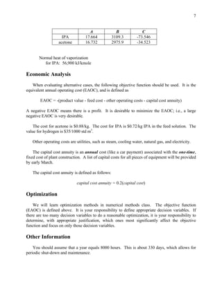
B
ln p* = A − (5)
T +C
(p* in mm Hg, T in K)](https://image.slidesharecdn.com/fulldesignforacetoneproduction-130308052330-phpapp02/85/Full-design-for-acetone-production-6-320.jpg)