A comparison of a novel robust decentralized control strategy and MPC for ind...
Application of a Reaction Kinetic Model for OnlLine Model Dynamic Control & Optimization
1. APPLICATION OF A REACTION KINETIC MODEL EOR ON-LINE MODEL
DYNAMIC CONTROL AND OPTIMISATION
D. M. Feord', P. J. CarIberg^ J. L. Bixby. T. Camp% P. K. Moore^
^Dow Deutschland Inc., Rheinmuenster, Germany
^The Dow Chemical Company, Freeport, Texas, USA
^The Dow Chemical Company, Midland, Michigan, USA
Reactors form the heart of most chemical processes. Industrial research often leads to
development of mechanistic kinetic simulations to describe the unit operation. With
proper considerations these models can be used for optimisation and control of
industrial reactors. This paper shows how the same kinetic model and physical property
predictor has been adapted for on-line control and optimisation in both batch and
continuous reactor systems
1. INTRODUCTION
The reactor is the central unit operation in the
chemical industry. Subsequent parts of the process
exist to clean up or correct deficiencies originating
there. Recognising this, industrial researchers often
focus on reaction fundamentals, developing kinetic
models to accurately describe the chemistry. A good
model holds knowledge about the reaction in a
statistically relevant form suitable for prediction.
When the model monitors and guides the operational
staff or guides a real-time operations optimization
(RTO) or forms the basis of dynamic control, this
knowledge can substantially improve reactor
operation.
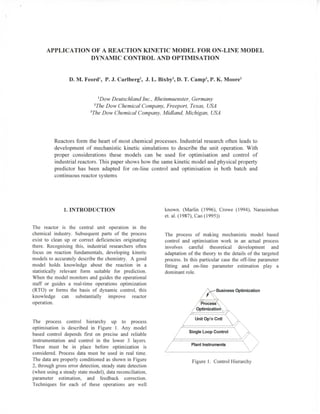
The process control hierarchy up to process
optimisation is described in Figure 1. Any model
based control depends first on precise and reliable
instrumentation and control in the lower 3 layers.
These must be in place before optimization is
considered. Process data must be used in real time.
The data are properly conditioned as shown in Figure
2, through gross error detection, steady state detection
(when using a steady state model), data reconciliation,
parameter estimation, and feedback correction.
Techniques for each of these operations are well
known. (Marlin (1996), Crowe (1994), Narasimhan
et. al. (1987), Cao(1995))
The process of making mechanistic model based
control and optimisation work in an actual process
involves careful theoretical development and
adaptation of the theory to the details of the targeted
process. In this particular case the off-line parameter
fitting and on-line parameter estimation play a
dominant role.
Business Optimization
Figure 1. Control Hierarchy
2. Data
C o n d i t i o n i n g
•Gross Error Deteotion
•Steady State Deteotion
•Data Reconciliation
•Parameter Estimation /
Feedback Correction
Y 'process ^V'X-
" / Optimization
J ^ setpoints
/ u n j l O p ' n C n t K ^
P r o c e s s
Model
Targets &
Constraints
process '
data
Plant I n s t r u m e n t s
Figure 2. RTO Data Flow
Examples will be given firstly of the application to the
improved control and flexibility of a batch reactor in
the process and secondly of the dynamic control and
optimisation of a series of continuous stirred tank
reactors carrying out the same chemistry in a similar
plant.
2. KINETIC SIMULATOR
A kinetic model of the reactions was developed from
laboratory data. In its simplified form the reactions
occurring are described below. They are irreversible
and either A or B, whichever is in excess, may be
reacted to extinction.
(1)
C + A^D + E (2)
D + B-^ F (3)
F + B-^G (4)
A + C-y H (5)
F+C^ H (6)
C and D are the desired products for this reaction.
Downstream of this reactor C is fully converted to D
and E is converted back to A. H is an unwanted by-
product whose formation must be suppressed by using
temperature control. G and F have a large affect on
the product physical properties and their formation
must be managed through feed composition and
temperature control.
A homogeneous liquid catalyst is used to catalyse the
reaction. Its concentration effect is accounted for in
the rate equations. The rate equations, described using
the Arrhenius equation, are temperature dependant.
The final product consists of a mixture of
components. Its measurable macroscopic physical
properties depend on the structure and concentration
of these components. The kinetic simulator predicts
the amounts of these components present based on
feed composition and reactor conditions. From the
predicted product composition, the product physical
properties can readily be calculated. With the kinetic
simulator plus physical property predictor, the user
can relate feed composition and reactor operating
conditions to final product properties.
3. PROCESS
A pre-mix tank is used for mixing A and B. Within
the raw material B are quantities of certain impurities
which greatly affect the reaction time and physical
properties of the finished product. The variability of
the impurities in B can be large and can change on a
daily basis. This tank is regularly analysed for its
chemical content. The mix tank feeds one of a series
of batch reactors or the first reactor in a series of
continuous stirred tank reactors. The reactors follow a
time temperature profile as the reaction occurs.
Control strategy for the temperature profile differs
slightly depending on the mode of operation. The
temperature profile is critical, firstly, for the thermal
stability of the reactor, as the reaction occurring is
highly exothermic, and secondly, for the product
properties and composition. The ultimate product
properties and composition are determined in this
reactor system. The relationship between reaction
temperature, reaction residence time and initial feed
concentrations is very important in determining
whether the final product will meet the requisite
specifications.
A is in large excess in this reaction, while B reacts to
near completion. However, even at its relatively low
concentration, B has a large effect on the reactivity
during downstream processing. Maintaining tight
control of the concentration of B in the reactor
product is crucial in avoiding upsets during
subsequent processing. There are also limits on F, G
and H to ensure that the final product leaving the
process is within specification.
4. BATCH PROCESS OPTIMISATION AND
CONTROL
Two objectives have been set as targets for model
control, firstly an increased and variable reactor
capacity in line with the rest of the process with no
deviation in the product properties and secondly
improved reactor product consistency. In order to
achieve this the kinetic simulator in the form of a
reactor model has been placed on-line, closed loop in
the digital control system (DCS). Off-line studies
were made using the model to optimise and re-
programme the temperature profile in the DCS. Due
to the structure of the temperature profile manual set
point changes to the temperature profile in the DCS
are possible but no automatic on-line optimisation
changes are possible. Therefore the off-line studies
3. are an important guide to the operational staff as to
the optimum temperature profile.
This is an effective means of composition and
physical properties control for the final product.
Both current and historical data are automatically
retrieved by the model and model data sent to the
DCS. A date and time stamp sent every time the
model runs is used to by the DCS to determine that
the model is still active. The table below indicates the
data transfer.
INPUT FROM DCS OUTPUT TO DCS
A & B raw material flows Time HHMM
B impurity concentrations Date MMDD
Batch catalyst charge Alarm to stop batch
Reactor temperatures Reactor heel volume
Reactor batch step Reactor Concentrations
Max product B cone. Product properties
Minimum product property
Table 1. Data transfer used for reactor model
In terms of process monitoring the model has three
important functions to fulfil in order to be able to
detect the concentrations required at the end of the
batch. These are described below,
• Monitors feed stock concentrations using
component mass balances from raw material flows
and concentrations for B and its important
impurities. Concentration profiles for each feed
tank are saved.
• Recognises reaction initiation when the catalyst
added with or to the raw material.
• Estimates actual reactor concentrations by
looping through on a regular defined basis,
collecting and conditioning temperature data,
integrating concentration profiles and storing this
as the initial conditions for the next integration.
Before the model was used as an on-line closed-loop
tool detailed analyses and comparison of its
predictions against measured values were made. This
was best accomplished with the model in on-line
open-loop mode in order to satisfy the functions
previously mentioned.
Once the model parameters were estimated and
verified the model was used in an on-line closed loop
mode. The aspects of the model control are detailed
below. Within the DCS the model:
• Detects when B has been reduced to below the
maximum final concentration. Sends a warning to
the operational staff via the DCS and the DCS
automatically starts the batch cooling step.
• Calculates how much of the current batch is to be
left in the reactor as a "seed" for the next batch.
Having defined an operation region for the
temperature profile off-line, in which physical
properties and impurity levels can be held within their
specification, the implementation of the model control
has delivered reduced batch times coupled with better
reactor product consistency. This is shown clearly in
Figure 3 where the end concentration of B is plotted
against the reactor residence time. A concentration
below but as close to 0.7 is desired. Before the model
implementation, with a fixed residence time the
variability in this quantity is large. With the
implementation of the model, not only is this scatter
greatly reduced, but batch cycle times have been
significantly reduced through temperature profile
optimization using the model off-line.
* 0.6
i
I
i 0.5
o = 0.05 CT = 0.17
^ Before mode!
inplcmcntalion
g After model
in|)lenientalion|
Figure 3 model influence on the reaction residence
time and cone, of B
Figure 4 shows that the product property has stayed
well within its limits, indicating that reactor
temperature optimisation and earlier reaction
completion did not adversely affect this product
physical property. It is rather, indicated that the
variation of this product is reduced, due to the better
finishing control on the reaction
Before model implementation
lOOO .
950 i
Figure 4 Variation Product Property
Figure 5 below also indicates that the by-product H
has not significantly changed due to the model
4. finishing the batch early with higher process
temperatures.
before mode] implemenrtation
o = 0,009
After model implementation
Figure 5 Variation of H
5. CONTINUOUS PROCESS OPTIMISATION
AND CONTROL
As with the batch reactor, the objectives for a
continuous reactor train are to produce more product
and to improve reactor product consistency. Here
reactor operation is controlled by manipulating
reactor residence times and temperatures. For a given
rate, this translates to the maintenance of liquid levels
and temperatures in each of the reactors. Figure 6
shows the continuous tank reactor system.
' conversion profile controlled by x and T
> manually set feed rate, levels, product type
> model manipulates temperatures
Serial CSTR Reactor System
Figure 6. CSTR Reactor System
For steady state operation, plant engineers set the feed
rate and reactor levels. The model manipulates the
reactor temperatures to achieve the targeted product
composition and final properties. In this mode, the
optimisation is implemented on-line with closed-loop
control. This type of optimisation structure and
implementation into the DCS has been described
previously (Carlberg and Feord (1997)).
Temperatures are manipulated to minimize an
objective function which scales and balances desired
composition and physical property targets. These
targets are identical to those described for the batch
reactor. The resulting set points are transferred to the
DCS for implementation in the Unit Operation or
Loop Control layers of the control pyramid.
This strategy of holding reactor levels and
temperatures at their steady state values works quite
well in handling small feed disturbances and gradual
rate changes. In these situations, making a smooth
adjustment in the temperature setpoints of the various
reactors is sufficient to avoid a significant variation in
the reactor product. However, large disturbances can
result in unsatisfactory product properties during the
transition to the new steady state conditions. In
particular, downstream processing constraints might
force an abrupt reduction of as much as 40% in the
production rate. The reactor heat exchangers are not
sized to adjust the temperatures quickly enough to
avoid excessive overreaction at the increased
residence time.
As a first step in addressing this problem, an on-line
version of the dynamic model was developed and
installed. It presently operates in a monitoring mode
and provides dynamic estimates of the concentrations
of species A through H. Intermediate reactors are not
routinely sampled. However, the limited
measurements that are available agree quite well with
the model estimates and support the use of the model
for improving the response to rate changes and other
process disturbances. Many of the species
concentrations were relatively insensitive to the
observed disturbances. Species B, however, did show
significant variability. In particular, a review of data
generated before and during a period of instability in
the downstream processes showed it had deviated
from its normal value during this time.
The second step in improving the transient response
involves the evaluation of candidate control strategies
using off-line simulation of the combined process plus
controllers. Given the observed sensitivity of the
process to the species B concentration, its domination
of the objective function, and the desire to have the
simplest feasible controller, the initial effort is
focusing on controlling species B. There is reason to
expect that if this is done, the other species will be
"pulled" along in a suitable manner. The level in the
final reactor of the series is traditionally maintained
near 50% to provide "surge" capacity. The strategy
currently being tested in simulation involves varying
the flow into the final reactor to control the B
concentration while the temperature moves toward its
new steady state value. This contrasts with the present
controller which maintains the level at setpoint during
the transition.
A parallel strategy applies to the control of the
upstream reactors. Note that while the desired B
concentration in the final reactor does not change, the
set points for this species in intermediate reactors are
affected by feed composition and rate changes.
However, as demand for increased throughput
5. (productivity) requires level set points nearer their
feasible maximums, there is less freedom to allow
these intermediate levels to float. Such constraints
mean that there is only limited control of these
intermediate B concentrations during transitions.
While direct control of B is lost when a level
constraint is met, the model is able to track its
concentration. In particular, an estimate of the
concentration in the penultimate reactor is available in
calculating the flow required into the last reactor.
In the anticipated event that these simulations uncover
a control strategy which promises an attractive
improvement over the present one in plant use, the
final step in the process will be to install, test, and
provide documentation for plant personnel to use, to
maintain, and, as conditions evolve, to modify the
controller. For a new controller ultimately to be
successful, its concept must be understood and
appreciated by plant management, engineering staff,
and operators. In this context the quotation attributed
to Einstein seems appropriate, "Keep it as simple as
possible, but not simpler."
6. CONCLUSIONS
This paper illustrates how the dynamic on-line control
and optimisation of a reactor can be accomplished. Its
basis is a simulation model which reflects the
fundamental kinetics and predicts key product
properties. Improved product quality and increased
capacity are two of the benefits of this work. The
simulation has been adapted for both batch and
continuous reactors.
7. BIBLIOGRAPHY
Carlberg, P. J. and Feord, D. M., 1997, Model Based
Optimisation and Control of a Reactor System with
Heterogeneous Catalyst, Proceedings of PSE 97 -
ESCAPE-?, pp 385-390, Trondheim
Cao, S., and Rhinehart, R.R., 1995, An Efficient
Method for On-Line Identification of Steady-State,
Journal of Process Control.
Crowe, CM., 1994, Data Reconciliation - Progress
and Challenges, Proceedings of PSE 94, pp 111-I2I,
Seoul, Korea.
Marlin, T. E., and Hrymak, A. N., 1996, Real-Time
Operations Optimization of Continuous Processes,
Chemical Process Control - V, Tahoe City, Ca.
Narasimhan, S., C.S. Kao and R.S.H.Mah, (1987),
Detecting Changes of Steady State Using the
Mathematical Theory of Evidence, AlChE J., 33,
1930.