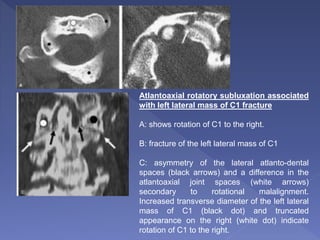
 During ancient times, spinal trauma and paralysis
was untreatable and fatal
 Spinal cord injury (SCI) still remains a significant
cause of disability
 The majority (81%) are males and the average age
is relatively young at 32.8 years.
 Approximately half the spinal cord injuries occur
from motor vehicle crashes. Falls from >10 feet,
gunshot wounds, motorcycle crashes, crush injuries,
and medical/surgical complications account for most
of the remaining cases
 In addition to the obvious quality-of-life
implications of such injuries, life expectancy
is also affected, being approximately half of
that of otherwise matched individuals
 Radiography
 Computed Tomography (CT)
 MRI
 Only one third of spinal trauma patients present
initially with a neurological deficit
 Moreover, important clinical features such as pain
from injury may be masked by other injuries,
medication, and drug and alcohol intoxication
 Defining the group of subjects who are at risk for
cervical spine fracture and therefore in whom
imaging is appropriate remains challenging.
The NEXUS study indicates that cervical spine imaging is not necessary in trauma
patients who meet all of the following five criteria:
1. No midline cervical spine tenderness
2. No focal neurological deficit
3. Normal level of alertness
4. No intoxication
5. No painful distracting injury
 NEXUS - National Emergency X-Ray Utilization Study, United States, published in 2000
 Source: Hoffman J, Mower W, Wolfson A, et al. Validity of a set of clinical criteria
to rule out injury to the cervical spine in patients with blunt trauma. N Eng J Med.
2000;343:94–99.
sensitivity - 99.6%
specificity - 12.6%
 Imaging of the cervical spine is not necessary if patients are alert (GCS 15) and all
of the conditions detailed below are met.
1. No high-risk factor present, including:
Age 65 or more years
Dangerous mechanism, including:
Fall from >3 meters/5 stairs
Axial load to head (diving)
High-speed vehicular crash (60 mph, rollover )
Bicycle crash
Motorized recreational vehicle crash
Paresthesias in extremities
3. Able to actively rotate neck (45 degrees left and right)
 Source: Stiell I, Wells G, Vandemheen K, et al. The Canadian C-spine rule for
radiography in alert and stable trauma patients. JAMA. 2001;286: 1841–1848.
2. Any low-risk factor is present, including:
Simple rear-end vehicular crash
mechanism, excluding:
Pushed into oncoming traffic
Hit by bus/large truck
Rollover
Hit by high-speed vehicle
Sitting position in emergency department
Ambulatory at any time
Delayed onset of neck pain
Absence of midline cervical tenderness
 The three-view radiography series
antero-posterior,
lateral, and
open mouth odontoid
is still the imaging modality of choice as initial
study for symptomatic patients
( as recommended by the American College of Radiology Appropriateness
Criteria and the Advanced Trauma Life Support (ATLS) course of the American
College of Surgeons )
 Single detector CT scan has a sensitivity of 98%
for fracture with a specificity of 93%
 With the new generation of 16 and up to 64
detector scanners, it is likely that CT today is
more accurate and more cost effective
 In summary, despite the aforementioned
recommendations, CT is being used for
screening cervical spine in high-risk patients,
particularly if CT is also to be used to evaluate
the subject's head
 Radiography remains appropriate in low-risk
subjects, as well as in those situations where CT
is not available.
 Only if ligamentous injury is suspected
 The AANS suggests that cervical spine
immobilization may be discontinued if “normal
and adequate” flexion-extension radiographs are
obtained in an awake patient with normal
radiographs or CT in the presence of neck pain
or tenderness
 In summary, no reliable evidence exists regarding
the appropriate role for flexion-extension
radiography in the acute evaluation of cervical
spine trauma.
The biomechanics of injury in the elderly differ from younger
adults–
1. Osteopenia, which is ubiquitous in this population, leads to a
lower energy threshold for fracture and affects fracture
location
2. Biomechanically, the spine in elderly patients is altered by
degenerative fusion usually in the lower cervical segments,
which leads to marked decrease in motion in the lower
cervical spine
3. Finally, the mechanism of cervical spine injury in the elderly
is substantially different than in younger adults with low-
velocity falls being more common in the elderly, and high-
energy motor vehicle crashes more common in younger
subjects
 Fractures of the upper cervical spine,
particularly C2, are more common in subjects
over 65 years of age than in younger subjects
 In very elderly subjects (> 75 yrs), C2
fractures account for nearly 50% of all
fractures
 Injuries to the lower cervical segments
become increasingly uncommon as patients
age.
 Cervical spine fractures are uncommon in
children
 The injury patterns are different, with cranio-
cervical junction injuries being more
prevalent in this group
 No validated method exists to identify
pediatric subjects who are of high risk for
fracture
 Special consideration regarding radiation dose
due to the inherent radio-sensitivity of
developing tissues in children compared to
adults
 Antero-posterior (AP) and lateral radiographs under
the age of 4
 AP, lateral and open mouth radiographs from 4 to 8
years old
 Children at 9 years of age and older are imaged with
the adult protocol. This is the approximate age at
which the fracture patterns revert to the adult
patterns.
 CT is reserved for those subjects in whom an
abnormality is identified on radiography.
 More common than fractures of the cervical spine
 The majority of these fractures, however, are
pathologic fractures that occur in the elderly as a
consequence of minor trauma and due to
underlying osteoporosis
 Non-pathological traumatic fractures of the
thoracolumbar spine do occur in approximately 2%
to 6% of admitted trauma patients
 The most common sites of injury are the T12 to L4
 CT reconstructions from an abdominal CT data set can be
considered an adequate substitute for thoracolumbar spine
radiographs for trauma patients
 ADV –
 obviate the need for dedicated thoracolumbar spine imaging with
radiography,
 more sensitive than radiography
 can be performed at minimal additional cost
 avoid additional radiation exposure
 The current rapid evolution of multidetector CT scanners
with increased numbers of detectors and higher spatial
resolution is expected to increase accuracy of such
reconstructions
ADV –
 readily available in all emergency centers
 can be performed with portable and fixed equipment
 the standard initial “screening” examination
 Cross-table lateral radiographs - inadequate to exclude
cervical spine injury, incomplete visualization of the
cervicothoracic and cranio-cervical junctions
 Oblique views - although useful in patients with unilateral
locked facet, are most valuable in adding two more views of
the cervico-thoracic junction in patients with equivocal lateral
that are not undergoing CT examination (low risk, obese
short-necked patients)
 Flexion-extension radiographs are not very
helpful in the acute setting because muscle
spasm in acutely injured patients precludes
an adequate examination
 Flexion-extension radiographs are helpful for
ensuring that minor degrees of
anterolisthesis or retrolisthesis in patients
with cervical spondylosis are fixed
deformities
ADV over single slice CT –
› faster acquisition of a volumetric data set
› Motion and mis-registration artifacts are minimized
› high-quality reconstructed images can be obtained
› Horizontal fractures that are oriented in the plane of the
scan, such as transverse odontoid fractures, may not
always be demonstrated by single CT without MPR (Sag
and Cor)
 CT may reveal more fractures than plain films and
may allow evaluation of the cervicothoracic and
cranio-cervical junctions, areas traditionally poorly
visualized on plain films
 Three-dimensional (3D) CT software programs
transform existing axial CT data into a 3D
rendering of the portion of the spinal skeleton
being examined
 3D CT reformations do not reveal a significant
number of unsuspected traumatic lesions but
they do provide improved definition and
comprehension of the extent and nature of
detected injuries
Advantages of 3D CT imaging includes:
 (a) ability to synthesize multiple 2D image
information, especially in areas with complex
anatomy,
 (b) visualization of complex injuries presenting
vertebral rotation or dislocation and loss of
alignment,
 (c) a more comprehensive assessment of cases
requiring surgical planning, and
 (d) better demonstration of displaced fractures.
 Surface rendering
 Maximum Intensity Projection (MIP)
 Volume rendering
Surface
rendering
Volume rendering
Maximum Intensity Projection (MIP)
1 – Anterior spinal line
2 – Posterior spinal line
3 – Spino-laminar line
Laminar Space –
Distance from
posterior aspect of
articular pillars (1)
to the spino-
laminar line (2)
• Used to indicate
rotational injuries
of the cervical spine
• Injury is suggested
when there is
abrupt alteration of
the space between
adjacent levels
Laminar
Space
Yellow line – pre-vertebral space (C2 <6 mm and C6 <20
mm in adults and C6 < 14 mm in children)
Black line – smooth contour
White arrow – Bulge due to anterior tubercle of atlas
Spinolaminar line –
 Any displacement in this line may be an indication of subtle traumatic vertebral
injury/dislocation.
 A line drawn through C1- 3 spinolaminar lines should intercept the C2
spinolaminar line.
 A displacement of the C2 spinolaminar line of more than 2 mm, compared with
a line drawn between the spinolaminar lines of C1 and C3, is abnormal.
Basion dental interval (BDI) -
the basion (white dot) should lie
within 12 mm of the top of the
odontoid process
The basion-axial interval (BAI) -
the PAL (white line) should lie
within 12 mm of the basion
 Concept initially evolved from a
retrospective review of thoracolumbar
spine injuries and observation of spinal
instability, it has also been applied to
the cervical spine.
 The posterior column consists
posterior ligamentous complex.
 The middle column includes the
posterior longitudinal ligament,
posterior annulus fibrosus, and
posterior wall of the vertebral body.
 The anterior column consists of the
anterior vertebral body, anterior
annulus fibrosus, and anterior
longitudinal ligament.
Three-column concept of the spine
(Denis)
Anterior Atlanto-
dental interval
(AADI)
 does not
normally exceed
3 mm in adults
and 5 mm in
children
• In adults, because of maturity of the transverse atlantal ligament, the AADI
remains constant in flexion and extension.
• In infants and children until the age of approximately 8 years, the AADI
varies in width in flexion and extension.
Diameter of the spinal
canal
 Difficulties in making accurate
measurements secondary to
differences in magnification or
focal spot-film distance.
 This problem can be overcome
by comparing the AP width of the
canal with that of the vertebral
body (canal / body)
 The normal ratio of the spinal
canal (white arrow) to the
vertebral body (black arrow) is
0.8 or more.
The normal atlanto-axial articulation in open-
mouth odontoid view
 The lateral margins of the lateral atlanto-axial
joints are symmetric and are on essentially in
the same vertical plane, plus or minus 1 mm.
 The joints of Luschka (Unco-
vertebral joints) including the
uncinate processes should be
symmetrically and vertically
aligned at all levels.
 The lateral cortical margins of the
lateral columns, which represent
the lateral cortex of the
anatomically superimposed
articular masses, appear as
smooth and gently undulating,
intact linear densities without
disruptions
 The apophyseal joints
are normally angled
approximately 35
degrees caudally
 Normal facet joints are
oriented on axial CT
examination so that they
resemble the sides of a
“hamburger bun”
 The anterior arch (red line in B) represents the anterior cortices of the axis
pedicles.
 The superior arc (yellow line in B) is a composite shadow produced by the cortex of
the notch at the base of the dens and that portion of the superior articulating facets
tangent to the central x-ray beam.
 The posterior arc (green line in B) is formed by the posterior cortex of the axis body
(posterior axial line).
 The “ring of C2” has a normal interruption at the inferior aspect (white arrow) due to
the foramen transversarium.
Location -
 Upper cervical injuries - include injuries to
the base of the skull (including the occipital
condyles or C0), C1, and C2.
 Lower cervical injuries (sub-axial) - include
injuries from C3 through C7
 When assessing stability in the spinal
column, the three-column theory of Denis
suggests that if two columns have failed, the
spinal column is unstable.
 Atlanto-occipital dislocation (AOD) is an uncommon injury
that involves complete disruption of all ligamentous
relationships between the occiput and the atlas
 Stability and function of the atlanto-occipital articulation
are provided by the cruciate ligament, tectorial membrane,
apical dental ligament, and paired alar ligaments, as well
as the articular capsule ligaments
 Death usually occurs immediately from stretching of the
brainstem, which can result in respiratory arrest
There are three principal forms of traumatic atlanto-
occipital dislocation -
 The first and the most common pattern is an
anterior and superior displacement of the
cranium relative to C1.
 The second is a pure superior displacement
(distraction) of the cranium.
 The third, and least frequent, is a posterior
dislocation of the cranium in relation to the spine
 The lateral cervical spine radiograph is most likely
to reveal the injury
 Sagittal CT reconstructions or sagittal magnetic
resonance imaging (MRI) can allow for the
diagnosis when plain radiography is inconclusive.
• >12 mm Basion Dental distance
• Separated occipital condyle and superior
surface of C1
Atlanto-occipital Distraction
Complete (disassociation) or partial (subluxation) ligamentous
disruption between occiput and C1 which can occur in one of
3 directions: (1) Anterior superior displacement of cranium
relative to spine most common; (2) Pure distraction injury with
superior displacement of cranium; or (3) Posterior dislocation
of cranium which is least common.
Numerous measurement techniques have been used to
assess craniovertebral junction trauma, many of which were
first defined in the plain film era. Many of these
measurements have been superseded by the direct soft tissue
visualization afforded by CT and MR. There is reasonable
literature support for use of the following measurements.
Basion-dental interval (BDI) is abnormal if > 10 mm on
sagittal CT.
Summed condylar displacement (sum of the bilateral
distances between midpoint of occipital condyle and C1
condylar fossa) is abnormal if > 4.2 mm.
Single side condylar distance measurement of > 2 mm is also
considered abnormal in adults. The 2 mm upper limit of C0-C1
spacing also applies to children up to 18 years of age.
Other measurements such as the Powers ratio and Lee lines
do not have sufficient sensitivity and specificity to recommend
their use. The Harris "rule of 12" for the BDI and basion-axial
interval are for plain film use only, so are very limited given the
use of CT for acute trauma evaluation.
Classification of
atlantooccipital
dislocation
(AOD)
MR Findings
• STIR, T2WI best shows ligamentous injury
○ Tectorial membrane disruption seen in 71% of 1 series of
16 pediatric patients
○ Nonvisualization of apical, alar, and anterior atlantoaxial
ligaments
– These ligaments are consistently seen in normal
patients with high-resolution MR centered on
craniocervical junction
○ Posterior atlantoaxial membrane often remains intact
○ No good data on patients showing only ligament injury
with normal alignment on MR and CT
– Cervical traction under fluoroscopy may be useful to
determine stability
• Widened, fluid-filled facet joints between condyle and C1 >
2 mm
○ May be unilateral
• Anterior or posterior displacement of C1 relative to base of
skull
○ Best seen on sagittal images
• Epidural &/or subdural hematoma in upper cervical spine
• Posterior fossa subarachnoid hemorrhage
• Vertebral artery injury
• Prevertebral hematoma
 OCF are rare, being found at postmortem
examination in 1% to 5% of patients who had
sustained trauma to the cervical spine and
head
 Clinical manifestations of OCF are highly
variable
 Not typically shown with conventional
radiography
Craniocervical Junction
Occipital condyle fractures are classified into 3 types
• Type I = comminuted fractures due to axial loading;
stable if contralateral side is intact
• Type II = occipital condyle fracture with skull base
fractures; most of these are stable
• Type III = avulsion fracture due to tensile force on alar
ligaments; may show occipitocervical instability
Recent data (Maserati 2009) suggests that initial evaluation
should be primarily concerned with identification of
craniocervical malalignment. Fusion or halo used in patients
with initial scans show fracture and malalignment, with rigid
cervical collar with delayed imaging follow-up for all others.
MR Findings
• STIR
○ Occipitoatloid joint subluxation, alar ligament
disruption,
joint effusion
○ Marrow edema
– May be minimal in hyperacute period
○ Prevertebral or nuchal ligament edema
○ ± cord edema or hemorrhage
○ ± foramen magnum extradural, subdural hemorrhage
• MRA
○ Evaluate vertebrobasilar arterial system for
patency/injury
DIFFERENTIAL DIAGNOSIS
Accessory Ossification Center(s)
• Anterior to occipital condyle
• Well corticated
Marrow Space Abnormality
• Infectious: Osteomyelitis
• Neoplastic
○ Metastatic neoplasms
○ Primary neoplasms
• Inflammatory: Rheumatoid arthritis
Plain film findings:
Difficult diagnosis due to overlapping of the
bony structures of the face, upper cervical
spine, and skull base.
 May be visible in open-mouth views that
include the condyles
 OCF are readily identified on axial or coronal
reformatted CT
Anderson-Montesano classification system (for OCF):
 ▪ Type I: Loading fracture of the occipital condyle, typically
comminuted and in a vertical sagittal plane, but where there
is no fracture displacement or associated craniocervical
instability.
 ▪ Type II: Skull-base fracture that propagates into one or both
occipital condyles
 ▪ Type III: Infero-medial avulsion fracture of the condyle by
the intact alar ligament, with medial displacement of the
fragment into the foramen magnum. Type III OCF are
considered potentially unstable because of an avulsed alar
ligament
Type I
Type II
Type III
UNSTABLE:
 ▪ Occipital condyle fragment displacement
>5 mm
 ▪ Occipito-atlantal dislocation
 ▪ Bilateral occipital condyle fractures
 Generally related to axial loading
 Neurologic compromise is relatively infrequent
with fractures of the C1 ring, presumably
because the axial compression mechanism
results in a burst configuration with expansion
of the spinal canal
 Jefferson Fracture
 Lateral Mass (C1) Fracture
 Isolated Fractures of C1
C1 Fractures
• Anterior arch = vertical or transverse with avulsion
from
longus colli
• Anterior arch bilateral fractures with posterior
atlantoaxial dislocation = plow fracture
• Lateral mass = stable if lateral ring intact; rare
• Posterior arch = common
• Jefferson = combined lateral mass displacement
relative
to C2 of 6.9 mm indicates disruption of transverse
ligament and potential for instability
 Classically, a four-point injury with fractures occurring at the
junctions of the anterior and posterior arches with the lateral
masses, the weakest structural portions of the atlas
 Most commonly there are two fractures in the posterior arch
(one on each side) and a single fracture in the anterior arch,
off the midline
 Mechanism - A JF is created by sudden and direct axial
loading on the vertex.
The lateral articular masses of the atlas become compressed
between the occipital condyles and the superior articular facets
of the axis. By its nature, this is a decompressive injury because
the bony fragments are displaced radially away from the neural
structures
Most common
Plain film findings:
Open-mouth odontoid view -
▪ Bilateral offset or spreading of the lateral articular masses of C1 in
relation to the apposing articular surfaces of C2
▪ It is often difficult to visualize the lines of fracture per se
Lateral view: (difficult diagnosis on the lateral view)
▪ Occasionally, the fractures are demonstrated on the lateral
projection (usually the posterior arch fracture)
▪ Increase in the atlanto-axial distance (>3 mm)
▪ Anterior or posterior displacement of the C1 spino-laminar line
▪ The retropharyngeal soft tissue may be abnormal in both contour
and thickness
AP view:
▪ Usually not visible on AP cervical spine radiograph
UNSTABLE (on radiography ):
 It has been suggested that the degree of offset
distinguishes between stable and unstable
Jefferson's fractures. An unstable JF is one in
which the transverse ligament is disrupted.
▪ Total C1 lateral masses offset of both sides > 7 mm
(adding the amount of lateral displacement of each
C1 lateral mass)
▪ Increase in the atlantoaxial distance (>3 mm)
Normal
Jefferson fracture
MR Findings
• T1WI
○ Prevertebral soft tissue swelling anterior to C1
○ Disruption of cortical margins of C1
• T2WI
○ Edema in prevertebral soft tissues
○ May see hyperintense cord edema if contusion is
present
– Low signal within cord edema concerning for
parenchymal hemorrhage
• MRA
○ Vertebral artery injury, if present, with dissection
or
occlusion
DIFFERENTIAL DIAGNOSIS
Congenital Variants, Clefts, Malformations of Atlas
• May show 1-2 mm offset of C1 pillars from those of C2
• Clefts found in 4% of posterior arches, 0.1% of anteriorarches
• 97% of posterior clefts are midline, 3% through sulcus of vertebral artery
• Various deficiencies of arch development can be seen
• Most are partial hemiaplasias of posterior arch
• Clefts, congenital defects show smooth or well-corticated edges
Rotational Malalignment of Atlas, Axis Pillars
• Generally seen unilaterally, with rotation and abduction of head
Pseudospread of Atlas in Children
• Common finding in children 3 months to 4 years of age evaluated for minor
trauma
• Seen in 90% or more of 2 year olds
• Caused by disparity in growth rates of atlas and axis
• Jefferson fracture rare in young children, greater plasticity, synchondroses of
C1 arch serve as "buffer"
 Axial images:
▪ Identify and establish the sites and number of C1 ring
fractures
▪ Establish separation between fracture fragments of the atlas,
if >7 mm the lesion is considered unstable
 Coronal reconstruction:
▪ Assess offset or spreading of the lateral articular masses of
C1 in relation to the apposing articular surfaces of C2
 Sagittal reconstruction:
▪ Assess increase in the atlanto-axial distance (>3 mm) and
anterior or posterior displacement of the C1 spino-laminar line

An unstable JF is one in which the transverse ligament is disrupted.
 Coronal reconstructions:
▪ Total C1 lateral masses offset of the two sides in excess of 7 mm
(adding the amount of lateral displacement of each C1 lateral mass)
 Sagittal reconstructions: Increase in the atlantoaxial distance (>3
mm)
 Axial views: >7 mm separation between fracture fragments of the
atlas
▪ Because multilevel fractures (C1 and C2) are considered unstable,
a cautious search for contiguous fractures is critical
Atypical Jefferson fracture
 Axial CT images show a displaced (>> 7
mm suggesting instability) single
fracture of the left anterior arch of C1
(white arrows) and left lateral
comminuted fracture of the posterior
atlas ring (black arrows).
 Avulsed fragments from the medial
surface of the left lateral mass of C1 are
noted (open arrowhead).
 Usually occur as a result of a lateral tilt
 May be limited to the lateral mass of C1, or more commonly,
occurs in association with occipital condyle fractures and/or
fracture of the articular process of C2
 Usually visible on the open-mouth view
 However, sometimes the abnormal cervico-cranial
prevertebral soft tissue contour is the only sign of injury in
plain films
 A fracture of the lateral mass of C1 is considered unstable
 usually stable
 should be distinguished from the Jefferson bursting
fracture and its variants
 The most common isolated fracture of C1 is a
bilateral vertical fracture through the posterior neural
arch
 Carries no risk of neurologic deficit
 This fracture must be distinguished from
developmental defects
Isolated fracture of posterior arch smooth margins of a partially
non-ossified posterior atlas
ring
 Approximately 25% are hangman fractures,
over half (58%) are odontoid fractures, and the
remainder are miscellaneous fractures
involving the body, lateral mass, or spinous
process
 Hangman Fracture (Traumatic
Spondylolisthesis of C2)
 Odontoid Fractures
 C2 Lateral Body Fractures
C2 Body Fractures (Fujimura 1996)
• Type I = extension teardrop fracture of anterior
inferior
endplate of C2
• Type II = horizontal shear fracture through
body (more
caudal than type III odontoid fracture)
• Type III = C2 body burst fracture
• Type IV = unstable sagittal cleavage fractures
 Injury is identical to that created by judicial hanging and thus the
designation of the hangman fracture
 Mechanism –
 most common form of this injury results from extension combined with axial
loading
 The full force of acute hyperextension of the head on the neck is transmitted
through the pedicles of C2 onto the apophyseal joints. The weakest points in this
chain are the interarticular segments of the pedicle. Thus, the arch of C2 is
fractured anterior to the inferior facet
 Hangman fracture is a bilateral fracture through the pars interarticularis
of C2
 The pars interarticularis is found between the superior and inferior
articular processes of C2
 Spinal cord damage is uncommon, despite frequent significant fracture
displacement, due to the wide spinal canal at this level
 Lateral view: The fracture usually is diagnosed readily on the lateral
radiograph in >90% of cases unless non-displaced.
▪ Prevertebral soft tissue swelling or hematoma, often absent
▪ Fractures are often anterior to the inferior facets. They are oblique, extending
from superior/posterior to inferior/anterior
▪ Positive axis ring sign, which will show posterior ring disruption from atypical
fractures extending into the posterior C2 vertebral body cortex
▪ “Fat C2 sign”
▪ Posterior displacement of the C2 spino-laminar line of >2 mm,
▪ An avulsion fracture of the anterior margin of the axis or anterior superior
margin at C3 is often present and identifies the site of rupture of the anterior
longitudinal ligament
 AP view: Usually not visible on AP cervical spine radiograph.
CT is valuable to exclude or verify fracture line extension into the vertebral
foramina or vertebral body, or to detect subtle concurrent adjacent injuries.
 Axial images:
▪ Identify the sites of C2 ring fractures and extension into the vertebral
foramina or vertebral body.
▪ Establish separation between fracture fragments of the pars inter-articularis
of C2
 Coronal reconstruction:
▪ Usually provides no additional information as to the nature of the hangman
fracture, but can be valuable to detect concurrent adjacent injuries.
 Sagittal reconstruction:
▪ Assess the fractures lines and posterior displacement of the C2
spinolaminar line ▪ Assess C2-3 disc space
▪ Establish separation and angulation between fracture fragments of the pars
interarticularis of C2
Fat C2 sign
C2 ring sign
UNSTABLE:
▪ More than 3 mm of fragment displacement or >15-
degree angle at the fracture site
▪ Abnormal C2-3 disc space
▪ C2-3 dislocation
▪Because multilevel fractures (C1 and C2) are
considered unstable, a cautious search for
contiguous fractures is critical.
 Type I fracture - an isolated “hairline” fracture,
with < 3 mm fragment displacement, < 15-
degree angle at the fracture site, and normal C2-
3 disc space
 Type II injuries - > 3 mm of fragment
displacement or more than a 15-degree angle at
the fracture site and an abnormal C2-3 disc
space
 Type III consists - changes that characterize
type II injury + C2-3 articular facet dislocation
Classification of dens fractures (Anderson and D'Alonso ) -
based upon the location of the fracture site with respect to the
dens
 Type I - an oblique fracture of the superior lateral aspect
of the dens, avulsed by the alar (“check”) ligament; this is
an extremely uncommon injury, occurring in < 4% of
odontoid fractures
 Type II - fracture at the base of the dens (most common -
comprising 60% of dens fractures )
 Type III - an oblique fracture of the superior portion of the
axis body caudal to its junction with the base of the dens
Odontoid
• Type I = avulsion at tip of odontoid
• Type II = transverse fracture of dens above C2 body
• Type III = fracture involving superior portion of C2
body
C2 Ring Fractures (Effendi 1981)
• Type I = bilateral pars fractures with < 3 mm anterior
subluxation (stable)
• Type II = displacement of pars fracture + anterior
translation of C2 with discoligamentous injury
• Type III = pars fractures with C2-3 facet dislocations
The radiologic diagnosis of odontoid fractures usually is established
using the lateral cervical and open-mouth odontoid view radiographs.
 Open-mouth odontoid view:
 Type II odontoid fractures - transverse or oblique transverse
fracture through the lower portion of the dens.
The transverse fracture at the base of the dens must be differentiated
from a developmental abnormality termed as os odontoideum.
 Os odontoideum is rounded, has a cortical margin around its
entire surface, and is usually more widely separated from the base
of the odontoid than a fracture, and with smooth margin.
Nonunion odontoid fractures may be impossible to distinguish from an
os odontoideum.
Lateral view: (Difficult diagnosis on the lateral view)
 Minimal displacement often precludes demonstration of the
fracture line.
 Positive axis ring sign will show posterior or anterior ring
disruption in type III fractures
 Type III fractures are almost always better visualized on the
lateral projection and may not be evident on the
anteroposterior view
 Anterior or posterior displacement of the C2 spinolaminar
line of >2 mm
 “Fat C2 sign” in type III fractures
 If the odontoid fragment is displaced by >5 mm, a 75%
nonunion rate results
 Odontoid fracture with anterior or posterior displacement of
the C2 spinolaminar line of >2 mm
 Multilevel fractures (C1 and C2) are considered unstable
 Odontoid fractures with atlanto-axial dissociation.
Type I odontoid fracture
Type II odontoid
fracture
Type III odontoid
fracture
 An isolated C2 lateral body fracture is rare
 is usually found incidentally when evaluating for other C2
traumatic pathology
 If a C2 lateral body fracture is found, other C-spine
pathology must be sought (ipsilateral occipital condyle, C1
lateral mass, and lower cervical spine fractures)
 Mechanism - axial compression with concomitant lateral
bending
 Radiographic findings include - impaction of the C2
component of the atlantoaxial articulation surface,
asymmetry of C2 lateral body height, and lateral tilting of
the arch of C1. Atlanto-occipital and atlantoaxial
dissociation can be seen
 Defintion - Acute traumatic atlanto-axial dissociation (AAD)
is a rare injury in which there is partial (subluxation) or
complete (dislocation) derangement of the lateral
atlantoaxial articulations
 Certain congenital conditions can be associated with AAD,
including Down syndrome, osteogenesis imperfecta,
neurofibromatosis, Morquio syndrome,
spondyloepiphyseal dysplasia congenita, and
chondrodysplasia punctata.
 Neurologic symptoms occur when the spinal cord is
involved
 The three mechanisms of AAD - are flexion
extension, distraction, and rotation.
 The most common abnormalities involve the
transverse ligament or odontoid process
 Type I AAD: AAD with rotatory fixation without anterior displacement of
the atlas.
The odontoid acts as the pivot and the transverse and alar ligaments are
intact.
This is the most common type of rotatory fixation and occurs within the
normal range of rotation of the atlanto-axial joint
 Type II AAD: Rotatory fixation with < 5 mm of anterior displacement of
the atlas. This is the second most common type and is associated with
deficiency of the transverse ligament.
 Type III AAD: Rotatory fixation with > 5 mm of anterior displacement of
the atlas. This degree of displacement implies deficiency of the TAL .
 Type IV AAD: Rotatory fixation with posterior displacement of the atlas.
This is the most uncommon type and occurs with deficiency of the
dens, such as in type II odontoid process fractures or unstable os
odontoideum (congenital or posttraumatic).
Atlantoaxial rotatory subluxation associated
with left lateral mass of C1 fracture
A: shows rotation of C1 to the right.
B: fracture of the left lateral mass of C1
C: asymmetry of the lateral atlanto-dental
spaces (black arrows) and a difference in the
atlantoaxial joint spaces (white arrows)
secondary to rotational malalignment.
Increased transverse diameter of the left lateral
mass of C1 (black dot) and truncated
appearance on the right (white dot) indicate
rotation of C1 to the right.
 Anterior translation of C1
evidenced by the
abnormally wide (>> 5
mm) anterior atlanto-
dental interval (AADI)
 Anterior position of its
spinolaminar line (yellow
line in B) with respect to
that of C2-3
spinolaminar lines
 Atlanto-axial rotational injury must be distinguished from
torticollis
 Torticollis, or “wry neck,” is more precisely defined as “acute
rotational displacement” and may be due to a variety of
conditions
 It is clinically manifested by simultaneous lateral tilt and rotation
of the head
 The causes of torticollis can be subdivided in two groups –
o Disorders of rotation of the atlantoaxial joint resulting in fixed or limited
rotation of the neck. This may occur spontaneously, secondary to
trauma, or in association with congenital anomalies or arthritides.
o Other disorders causing limited rotation of the neck without primarily
involving the atlantoaxial joint, where the primary abnormality is in the
sternocleidomastoid muscle (congenital fibrosis, lymphadenitis, tumors
of the cervical spine, painful neck).
 Rotatory subluxation is sometimes observed after
upper respiratory infection or after head and neck
surgery.
 ‘Grisel syndrome’ is the occurrence of atlanto-
axial subluxation (AAS) in association with
inflammation of adjacent soft tissues.
 Torticollis is usually self-limited and occurs mainly
in children to young adolescents. The symptoms
usually disappear in 4 to 5 days.
 Most cases resolve spontaneously, although in a
few instances the rotatory deformity becomes
fixed and irreducible. The fixation usually occurs
within the normal range of rotation of the atlanto-
axial joint.
 Case of torticollis due to congenital fibrosis of sternocleidomastoid
 History helps in differentiating Torticollis from traumatic AAR
 Flexion Injuries –
Clay-shoveler fracture, Anterior Subluxation , Simple Wedge
Compression Fracture, Flexion Teardrop Fracture
 Flexion rotation injuries -Unilateral Facet Dislocation
 Extension injuries – Dislocation, Extension teardrop
fracture, Laminar fractures
 Extension rotation – pillar fracture
 Vertical Compression - Burst Fracture
 Avulsion injury of the spinous process of C6, C7, or
T1 (in order of frequency).
 The fracture results from abrupt flexion of the head
and neck against the tensed ligaments of the
posterior aspect of the neck
 The name is derived from the cervical spine injury
sustained by Australian clay miners
 Posterior longitudinal ligament remains intact
 The typical clay-shoveler fracture is both
mechanically and neurologically stable.
 Occurs when posterior ligamentous complexes (nuchal ligament,
capsular ligaments, supraspinous and infraspinous ligaments,
ligamenta flava, posterior longitudinal ligament) rupture and a
minor tear of the annulus posteriorly
 The anterior longitudinal ligament remains intact.
 No associated bony injury is seen.
 Mechanism - Anterior subluxation is caused by a combination of
flexion and distraction.
 Anterior subluxation is considered clinically significant because of
the morbidity associated with the 20% to 50% incidence of failure
of ligamentous healing or “delayed instability.”
Lateral view:
The findings of AS seen in neutral position become exaggerated upon flexion
and are reduced in extension
 Abrupt hyperkyphotic angulation at the level of ligamentous injury
 Widening of the interspinous distance at one level (“fanning”), relative to
adjacent levels
 Incongruity and lack of parallelism of the contiguous facets
 Disc space is widened posteriorly and narrowed anteriorly
 Small anterior superior compression fractures of the subjacent vertebral
body
 Increased thickness of the prevertebral soft tissues as a result of
hematoma formation
AP view:
 Widening of the interspinous distance. This sign
represents the “fanning” seen on the lateral
radiograph.
 Lateral dislocation (also called lateral
translation) may occur without significant
anterior or posterior displacement.

Subtle anterior subluxation
UNSTABLE:
 ▪Anterior translation of the vertebral body
>3.5 mm relative to the subjacent vertebra
 Vertebral body angulation >20 degrees
relative to the adjacent vertebra.
 Mechanism - result of compression of the anterior
aspect of the vertebral body
 Loss of vertebral body height, predominantly
anteriorly
 The simple wedge fracture is characterized
radiographically by an impaction fracture of the
superior endplate of the involved vertebral body
while the inferior endplate remains intact
 The simple wedge fracture is considered
mechanically stable.
 Extreme form of anterior subluxation
 Ligamentous disruption and significant anterior
displacement of the spine at the level of injury
 It usually occurs in the lower cervical spine
 The spinal canal is severely compromised by this
displacement, and spinal cord injuries are frequent
 MRI is the modality indicated for subsequent imaging
of patients with BFD as it best assesses the nature
and extent of spinal cord injury as well as any
associated disc and ligamentous injury
Plain film findings:
Lateral view:
 Displacement of >50% of the antero-posterior diameter of
the vertebral body
 Dislocation of articular facets
 Narrowing of the disc space at the injured level
 Dislocation may be incomplete (perched facets), with
varying degrees of antero-listhesis of facets of one body
relative to another..
 Increased thickness of the pre-vertebral soft tissues
secondary to hematoma formation.
AP view:
 Increased inter-spinous distance at the level of dislocation.
Anterior subluxation
< 25 %
Unilateral facet
dislocation
25 – 50 %
Bilateral facet
dislocation
>> 50 %
CT findings:
CT is valuable for detection of radiographically
occult fractures of the posterior arch or articular
facets.
Axial images:
 Fractures undetectable at plain radiography may
be revealed.
 “Reverse hamburger bun” sign is useful in
establishing a diagnosis of facet dislocation
 “Naked facet sign”: refers to the CT appearance
of uncovered articulating processes. On axial CT
images, there are bilateral solitary non-
articulating facets with loss of the joint space
Bilateral facet dislocation – Double vertebral body sign
Naked facet sign
 represents the most severe injury of the cervical spine
 highly unstable injury
 typically involving the lower cervical spine (especially C5)
 there is also complete disruption of all soft tissues at the
level of injury, including the posterior longitudinal ligament,
intervertebral disc, and anterior longitudinal ligament
 typical large triangular fracture fragment of the anteroinferior
margin of the upper vertebral body (teardrop fragment)
 The flexion teardrop fracture can be distinguished from the
similarly named hyperextension teardrop fracture by the
larger size of the triangular fragment and by distraction of
the posterior elements (indicating the flexion mechanism).
 most often encountered in elderly patients with severe
spondylosis or with spinal ankylosis from other etiologies
 Mechanism - In hyperextension fracture dislocation the
posterior spinal elements experience impaction forces,
producing loading fractures of the articular pillars, posterior
vertebral body, laminae, spinous process, or pedicles
 Characteristically, the spine above the level of injury is
posteriorly displaced (retrolisthesis), the intervertebral disc
space is widened anteriorly and narrowed posteriorly and
the facet joints are disrupted
Hyperflexion
• Simple compression fracture
• Anterior subluxation: Posterior ligament
disruption
• Bilateral interfacetal dislocation: Unstable
• Flexion teardrop fracture: Unstable
• Clay shoveler's fracture: Avulsion of spinous
process of
C7-T1
Hyperflexion and Rotation
• Unilateral facet dislocation (locked facet)
• May have associated facet fracture
• Radiograph shows forward displacement of vertebra
<
1/2 AP diameter of cervical vertebral body
Hyperextension and Rotation
• Pillar fracture
Vertical Compression
• Jefferson fracture = fractures of both anterior and
posterior rings with 2, 3, or 4 parts with radial
displacement
• Burst fracture = middle column involvement with bony
retropulsion
Hyperextension
• Hyperextension dislocation
• C1 anterior arch avulsion fracture = longus colli insertion
around anterior tubercle of C1
• Extension teardrop fracture of C2
• C1 posterior arch fracture = compressed between
occiput and C2 spinous process
• Lamina fracture = between articular mass and spinous
process
• Hangman's fracture = bilateral pars fractures of C2
• Hyperextension fracture: Dislocation = bilateral facet
fracture ± dislocation
Plain film findings: Cervical hyperextension injuries often show minimal radiographic
abnormalities, even with severe or unstable lesions. The momentary posterior
displacement of the involved vertebra is usually completely reduced when the
causative force disappears.
Lateral view:
 Prevertebral soft tissues
 Avulsion fracture fragment from the anterior aspect of the inferior endplate of the
superior vertebra. The transverse dimension of the avulsed fragment exceeds its
vertical height (c/w flexion tear drop fragment)
 Normally aligned vertebrae.
 Anteriorly widened disc space.
UNSTABLE:
 ▪ Hyperextension dislocation is mechanically unstable.
 • 3 major components including morphology
of spinal
 column disruption, integrity of disco-
ligamentous
 complex, and neurologic status
 • Within each component, subgroups are
graded from
 least to most severe
• 3 components give final numeric score that
directs treatment
• Injury mechanism, integrity of posterior
ligamentous complex, and neurologic status
Denis – Three column theory:
Compression
Type A: Both endplates fractured
Type B: Superior endplate fracture
Type C: Inferior endplate fracture
Type D: Lateral wedging
Burst
Type A: Both endplates fractured
Type B: Superior endplate fracture
Type C: Inferior endplate fracture
Type D: Burst fracture with rotatory
component
Type E: Burst fracture with lateral
flexion
Flexion-distraction
Type A: Single level, classic Chance
fracture with bone disruption only
Type B: Single level, soft
tissue/ligamentous disruption
Type C: Two level disruption through
bone at middle column
Type D: Two level disruption through soft
tissues at middle column
Fracture-dislocation
Type A: Flexion rotations through body
Type B: Flexion rotation through disc
Type C: Posteroanterior shear injury
Type D: Posteroanterior shear injury
with floating lamina
Type E: Anteroposterior shear injury
Type F: Flexion distraction
Denis 3 Column Model (1983)
• Anterior: ALL, anulus, anterior vertebral body
• Middle: Posterior wall of vertebral body,
anulus, PLL
• Posterior: Facets, posterior elements,
posterior
ligaments
• 3 column model also relevant to lower cervical
injuries
Denis Subclassification of Burst Fracture (1984)
• Denis type A
• Axial load force; anterior and middle columns involved,
unstable
• Upper and lower endplates involved
• Denis?type B and C
• Flexion and axial load, anterior and middle columns,
possibly unstable
• B upper endplate involved (most common)
• C lower endplate involved
• Denis type D
• Axial load and rotation, all columns, unstable
• Atlas modification of D injuries (1986)
• D1 burst lateral translation, D2 burst sagittal translation
• Denis?type E
• Lateral compression, all columns, possibly unstable
Magerl AO Pathomorphologic System (1994)
• A, B, C types reflecting common injury patterns
• Each type has 3 groups, each with 3 subgroups (3-3-3
scheme)
• Type A vertebral compression fractures due to axial
loading without soft tissue disruption in transverse plane(66%)
• Type B distraction of anterior and posterior elements
with soft tissue disruption in axial plane (14.5%)
• Type C with axial torque forces giving anterior and
posterior element disruption with rotation (19%)
• Severity progresses through type A to C, as well as within
types, groups, and subdivisions
• Stable type A1 most common (wedge fracture)
• A3 corresponds to "burst fracture" of Denis classification
• Unstable: A3.2, A3.3, B, C types
McCormack "Load-Sharing" Classification (1994)
• Specifically designed to evaluate need for anterior
column reconstruction following pedicle screw
stabilization
• Also useful as a more generic guide to the
magnitude of
comminution and biomechanical instability
• Comminution graded
• → amount of vertebral of body damage
• → fragment of spread at fracture site
• → degree of corrected kyphosis
 The spinal canal size in the thoracic region averages
16 (AP) by 16 mm (trans), whereas in the lumbar
spine the canal averages 17 (AP) by 16 mm (trans)
 Thoracolumbar junction is a region of transition and
accounts for a greater propensity for injuries in this
region - 2/3rd of all thoracolumbar fractures occur at
T12, L1, or L2
 Thoracic spinal trauma has more chances of
neurological damage because
 lumbar spine is more capacious
 cord terminating as the conus medullaris at the L1 level
 cauda equina, unlike the spinal cord, are relatively resistant
to blunt trauma
Radiologic Hallmarks of Instability in thoraco-lumbar spine
1. Displacement/translation >2 mm, indicative of disruption to the main
ligamentous supports.
2. Widening of the interspinous space, widening of facet joints and/or
widening of the interpediculate distance.
3. Disruption of the posterior vertebral body line equates to a disrupted
anterior and posterior column or articular process fractures.
4. Widened intervertebral canal, indicative of sagittally orientated
vertebral bodytrauma.
5. Vertebral body height loss >50%.
6. Kyphosis >20 degrees.
Source: Daffner et al.
 typical anterior wedge compression fracture
 upper and mid-thoracic spine due to the kyphotic curvature
 Neurologic instability is rare in this fracture
 Usually involves only the superior endplate
 It is distinguished from Scheuermann disease and physiologic
anterior vertebral wedging; the latter two usually involve both
superior and inferior endplate
 Bimodal distribution, occurring in the young (in the context of
high-speed trauma) and in the elderly (osteoporosis).
 Axial/burst fractures, in contradistinction, have symmetrical
reduction in height of the anterior and posterior vertebral margins
 burst fractures of the thoracolumbar junction
and lumbar spine
 classically occurs after landing on both feet or
buttocks following a fall from a height (lover's
fractures when associated with bilateral
calcaneal fractures)
 Rarely, due to seizure or electrocution
Mechanism –
 Axial compression of the vertebral body from above by the
nucleus pulposus, which explodes into the superior
vertebral endplate to result in centripetal displacement of
the body and its fracture fragments
 The retropulsion of the posterior aspect of the vertebral
body into the spinal canal is pathognomonic of a burst
fracture
 As the PLL is often intact, spinal traction can reduce this
displaced fragment by tightening the PLL
 Applying the three-column principle, there is a minimum
two-column disruption (the anterior and middle) in a burst
fracture
Determinants of Burst Fracture Instability
 Widened interspinous and interlaminar
distance
 Kyphosis >20 degrees
 Dislocation
 Vertebral body height loss greater than 50%
 Articular process fractures
 Posterior bowing of
the vertebral body
margin is diagnostic
of an axial
compression (burst)
fracture.
Laminar spit
fracture
 Essential to alert the clinician about the presence of a laminar
split fracture
 high association with posterior dural laceration
 Impaction of the thecal sac with the vertical fracture results in this
characteristic laceration
 The laminar split fracture almost exclusively occurs with the burst
fracture, with an incidence of 7.7% of such fractures having a
dural tear
 The presence of a dural tear requires detection prior to surgery,
as reduction of the neural extrusion and closure of the dural
laceration requires a posterior approach and should be performed
prior to any spinal reduction maneuver, which would worsen
compression of the extruded neural contents.
 Once a burst fracture is diagnosed, as with
many vertebral fractures, radiographic survey
of the entire spine is recommended as
noncontiguous level involvement may occur
in as many as 6.4% to 34%
 Neurologic instability (actual or impending)
has been defined as spinal canal stenosis
50% of normal
 most common at the thoracolumbar junction
 separation in a cranial-caudal direction
 Mechanism - result of hyperflexion of the
upper thoracic spine while the lower spine
remains relatively fixed
 classically caused by a deceleration-type
motor vehicle accident
 The resultant fracture has been classically
described as the “Chance fracture”
 With the routine use of conventional three-
point restraint (shoulder harness and lap belt),
the incidence of the classic Chance fracture
has decreased and burst fractures are now
more prevalent
Chance
fracture
Classic Variants
“Classic Chance fracture” :
 The classic Chance fracture accounts for approximately 50%
of Chance-type injuries
 A “classic” Chance fracture - consists of a pure osseous
injury in which there is a horizontal split through the spinous
process, lamina, pedicles, resulting in a small anteroinferior
corner fracture of the lower vertebral body
 acutely unstable
 purely an osseous disruption; it also has excellent healing
potential with good prognosis for long-term stability
 Incidence of neurologic deficit is low, estimated at 10%
 AP radiographs - “double” spinous process,
interspinous distance widening, and horizontal
fractures through the pedicles
 lateral radiograph is often unreliable due to
overlap
Chance variants –
 are either a combined osseous/soft tissue injury
or pure
 The fracture may extend through the posterior
elements as for the classic Chance fracture, but
continues anteriorly through the disc or it may
involve the posterior ligaments and vertebral
body. soft tissue disruption.
 typically results in a severe and unstable
three-column injury, with anterior, posterior, or
lateral subluxation, as well as posterior
element fracture or ligamentous disruption
 The force vectors in this type of injury are both
enormous and complex
 neurologic impairment is frequent
 high association with thoracic and abdominal
injury
 The resultant radiographic pattern is
characterized by posterior element impaction,
with fractures (often comminuted) of the spinous
process, lamina, or facets, in association with
anterior disc widening or avulsion fracture of the
anterior endplate
 If severe enough, the injury may result in the
“lumberjack fracture-dislocation” in which there
is complete loss of continuity of the upper and
lower spinal segment associated with an
extremely high rate of paraplegia and dural tear
Mechanism
 The injury should serve as a sentinel sign,
alerting one to the possibility of other injury
 For example, an isolated L5 transverse
process fracture is commonly seen in
association with a vertically oriented sacral
fracture (Malgaigne fracture/dislocation) on the
same side
Transverse process
fracture associated
with a sacral fracture
Isolated sacral
fractures are
uncommon
Transverse fractures-
• most common type
• Common at S3-S4
level
• High horizontal
fractures occur from
high falls (suicidal
jumper’s fracture)
Vertical fractures –
• Usually indirect
trauma to pelvis
• Usually runs entire
scrap length
 Most are transversely oriented
 AP radiograph – not useful
 Lateral radiography – anteriorly tilted /
displaced coccyx
 The greatest impact that MRI has made in the
evaluation of SCI has been in assessment of the
intracanalicular and paraspinal soft tissues
 MRI has replaced myelography and CT
myelography as the primary imaging option to
assess for compression of the spinal cord
 An MRI examination in the acute period is
warranted in any patient who has a persistent
neurologic deficit after spinal trauma
 Requires special consideration before MRI with regard to patient
transfer, life support, monitoring of vital signs, fixation devices,
choices of surface coils, and pulse sequences
 several manufacturers offer MRI-compatible ventilators
 MRI-compatible monitors are now available that can relay heart
rate, respiration, blood pressure, and oxygenation information
directly into the MRI control area.
 Indwelling central venous catheters with thermocouples and
conventional intravenous medication pumps are prohibited in
the MRI environment
 Currently, MRI does not offer any advantage
over plain radiography or high-resolution
multidetector CT (MDCT) in the evaluation of
associated osseous injuries following spinal
trauma
Chance fracture
(GRE)
 MRI is the only imaging modality available that
directly visualizes changes to the ligaments as a
result of trauma
 ligaments appear relatively hypointense to other
structures on all MRI pulse sequences
 Edema or tear - increase in signal intensity on T2-
weighted or GE images because of an increase in
free water content from extracellular fluid or
adjacent hemorrhage
 Because of the similarity in imaging characteristics,
distinction between a ligament fragment and cortical
bone fragment may prove difficult on MRI
• Extensive
degenerative changes
noted but no gross
evidence of
malalignment
• The ALL, LF and
PLL are disrupted.
• There is widening
of the interspinous
distance
• Edema in the
posterior paraspinal
soft tissues
• damaged
intervertebral disc
Discontinuity of the ligamentum flavum and
edema in the posterior paraspinal
musculature
 Standard MR pulse sequences are typically capable
of receiving signals from tissues that have T2
relaxation properties greater than 10 milliseconds
 However, the intrinsic T2 relaxation of ligaments is
typically <1 millisecond. This is why ligaments are of
low signal on conventional MRI.
 The typical echo times of the UTE sequence are on
the order of 0.08 millisecond and are therefore
capable of capturing signal from less conspicuous
structures
 Ultrashort TE imaging of the transverse ligament of C1,
 Entire transverse ligament as a high signal intensity structure
(arrows).
 The transverse ligament is usually difficult to identify using
standard clinical MR sequences.
can be classified as either disc injury or disc
herniation
 Disc injury - is implied whenever there is
› asymmetric narrowing or widening of an isolated
disc space on sagittal images and
› focal hyperintensity of the disc material on T2-
weighted images
› potentially hemorrhagic MR signal changes of a
damaged disc may therefore be, in part, due to
damage to the adjacent endplates
 Disc herniation –
 similar MRI appearance to nontraumatic disc herniation
• acute angulation of C3 on C4
with spinal cord compression
• large herniated disc fragment (arrow)
compressing the spinal cord
• free edge of the ruptured PLL adjacent
to the disc fragment
 The imaging characteristics of epidural hematomas are
variable as they depend on the oxidative state of the
hemorrhage and the effects of clot retraction
 In the acute phase,
 isointense with spinal cord parenchyma on T1-weighted images
 isointense with CSF on intermediate- and T2-weighted
sequences
 The epidural collection may be difficult to distinguish from the
adjacent CSF in the subarachnoid space.
 This distinction can often be made by the hypointense dura,
which separates the two compartments
• A large dorsal epidural hematoma is displacing the posterior
margin of the dura
• The roots of the cauda equina are compressed against the
vertebral body by the hematoma
 Investigations have suggested that damage to
the vertebral arteries can be demonstrated
angiographically in up to 40% of patients
following cervical subluxation/dislocation
 But are mostly clinically occult
 Dissection of the vertebral artery is more
frequent than carotid artery dissection following
fracture/subluxation because a portion of the
cervical vertebral artery is contained within the
foramen transversarium
 MRA is an appropriate screening test to identify
patients who may require subsequent catheter
angiography
 A 2D TOF sequence is effective in screening the
extracranial vasculature for occlusion
 Resolution limits the effectiveness of detecting
subtle intimal injuries associated with dissection
 Use of black-blood techniques is advocated to
improve detection of sub-intimal dissections without
occlusion
 Clinically occult
vertebral artery
thrombosis after
unilateral facet
dislocation
 3D GRE acquisition
shows an oval area
of low signal
intensity in the right
foramen
transversarium
 Axial FSE image
shows a high-
signal-intensity
thrombus
 The depiction of parenchymal SCI on MRI not
only correlates well with the degree of
neurologic deficit, but it also bears significant
implications in regard to prognosis and potential
for neurologic recovery
 Imaging characteristics are due to accumulation
of edema and hemorrhage within the substance
of the cord parenchyma
Spinal cord injury without
radiographic abnormality
(SCIWORA)
absence of an obvious
fracture or subluxation
edema within the spinal
cord at the C3-4 level
(arrow) and prevertebral
edema
T2-weighted MRI with
fat suppression shows
the compression of the
spinal cord
 The most common location is within the
central gray matter of the spinal cord
 Centered at the point of mechanical impact
 In the acute phase following injury,
deoxyhemoglobin is the most common species
generated.
 Thus, the hemorrhagic component is depicted as a
discrete area of hypointensity on the T2-weighted
and GE images
 Detection of a sizable focus of blood (>10 mm in
length on sagittal images) in the spinal cord is often
indicative of a complete neurologic injury
 small focus of hyperacute
hemorrhage at C1-2
(arrow) and very subtle
high-intensity edema
Two days later, more
obvious edema
extending down to C4
and clear hemorrhage
in deoxyhemoglobin
state is seen,
particularly on axial
GRE (C), where
hemorrhage is noted
within central portion
of spinal cord
 focus of abnormal high signal intensity on T2-
weighted images
 Edema involves a variable length of spinal
cord above and below the level of injury, with
discrete boundaries adjacent to uninvolved
parenchyma
 In children, fractures and severe injuries to the
spine are relatively rare
 The anatomy and biomechanics of the growing
spine, larger head size relative to body size,
 greater flexibility of the spine and supporting structures,
 incomplete ossification, as well as
 greater elasticity and compressibility of the bone,
produce failure patterns different from those seen
in adults
 Anatomic differences between the pediatric and
adult cervical spine are prominent until
approximately 8 – 10 years of age
 SCIWORA is far more common in younger
children than in older children
 Pseudosubluxation –
normal physiologic displacement of C2 on C3, and
to a lesser extent C3 on C4, can mimic the
appearance of a true cervical spine injury
~ 40% of children under the age of 8 demonstrate
pseudosubluxation at the C2-3 level
• Spino-laminar line
displacement within 1.5 mm of
each other on both flexion and
extension views confirms the
pseudo-subluxation
• A measurement of >2 mm is
definitely abnormal, indicating
a true injury
• Measurement of 1.6 to 1.9 mm
is considered indeterminate
 Imaging plays a pivotal role in assessing the mechanical and
neurologic stability of the traumatized thoraco-lumbar spine.
 Radiography is still preferred in low risk “reliable” (awake, alert,
normal mental status, and no significant distracting pain) subjects.
 CT is the preferred imaging modality in subjects at high risk of
injury, however, because of higher sensitivity and specificity.
 CT, with the use of high-resolution multiplanar and 3D
reformations, has resulted in improved fracture pattern
classification with better differentiation between stable or unstable
injuries.
 MRI is still the only imaging method that demonstrates the soft
tissue components of injury and provides an objective assessment
of the damaged spinal cord's internal architecture
 Spinal Trauma: Imaging, Diagnosis, and
Management, 1st Edition, Schwartz, Eric
D.; Flanders, Adam E. (Copyright ©2007
Lippincott Williams & Wilkins)
 Diagnostic imaging Spine 3rd edition
(2015)
 CT and MRI of The Whole Body 6th edition
(2016)

Ariunaa spine trauma

  • 2.
     During ancienttimes, spinal trauma and paralysis was untreatable and fatal  Spinal cord injury (SCI) still remains a significant cause of disability  The majority (81%) are males and the average age is relatively young at 32.8 years.  Approximately half the spinal cord injuries occur from motor vehicle crashes. Falls from >10 feet, gunshot wounds, motorcycle crashes, crush injuries, and medical/surgical complications account for most of the remaining cases
  • 3.
     In additionto the obvious quality-of-life implications of such injuries, life expectancy is also affected, being approximately half of that of otherwise matched individuals
  • 4.
     Radiography  ComputedTomography (CT)  MRI
  • 5.
     Only onethird of spinal trauma patients present initially with a neurological deficit  Moreover, important clinical features such as pain from injury may be masked by other injuries, medication, and drug and alcohol intoxication  Defining the group of subjects who are at risk for cervical spine fracture and therefore in whom imaging is appropriate remains challenging.
  • 6.
    The NEXUS studyindicates that cervical spine imaging is not necessary in trauma patients who meet all of the following five criteria: 1. No midline cervical spine tenderness 2. No focal neurological deficit 3. Normal level of alertness 4. No intoxication 5. No painful distracting injury  NEXUS - National Emergency X-Ray Utilization Study, United States, published in 2000  Source: Hoffman J, Mower W, Wolfson A, et al. Validity of a set of clinical criteria to rule out injury to the cervical spine in patients with blunt trauma. N Eng J Med. 2000;343:94–99. sensitivity - 99.6% specificity - 12.6%
  • 7.
     Imaging ofthe cervical spine is not necessary if patients are alert (GCS 15) and all of the conditions detailed below are met. 1. No high-risk factor present, including: Age 65 or more years Dangerous mechanism, including: Fall from >3 meters/5 stairs Axial load to head (diving) High-speed vehicular crash (60 mph, rollover ) Bicycle crash Motorized recreational vehicle crash Paresthesias in extremities 3. Able to actively rotate neck (45 degrees left and right)  Source: Stiell I, Wells G, Vandemheen K, et al. The Canadian C-spine rule for radiography in alert and stable trauma patients. JAMA. 2001;286: 1841–1848. 2. Any low-risk factor is present, including: Simple rear-end vehicular crash mechanism, excluding: Pushed into oncoming traffic Hit by bus/large truck Rollover Hit by high-speed vehicle Sitting position in emergency department Ambulatory at any time Delayed onset of neck pain Absence of midline cervical tenderness
  • 8.
     The three-viewradiography series antero-posterior, lateral, and open mouth odontoid is still the imaging modality of choice as initial study for symptomatic patients ( as recommended by the American College of Radiology Appropriateness Criteria and the Advanced Trauma Life Support (ATLS) course of the American College of Surgeons )
  • 9.
     Single detectorCT scan has a sensitivity of 98% for fracture with a specificity of 93%  With the new generation of 16 and up to 64 detector scanners, it is likely that CT today is more accurate and more cost effective  In summary, despite the aforementioned recommendations, CT is being used for screening cervical spine in high-risk patients, particularly if CT is also to be used to evaluate the subject's head  Radiography remains appropriate in low-risk subjects, as well as in those situations where CT is not available.
  • 10.
     Only ifligamentous injury is suspected  The AANS suggests that cervical spine immobilization may be discontinued if “normal and adequate” flexion-extension radiographs are obtained in an awake patient with normal radiographs or CT in the presence of neck pain or tenderness  In summary, no reliable evidence exists regarding the appropriate role for flexion-extension radiography in the acute evaluation of cervical spine trauma.
  • 11.
    The biomechanics ofinjury in the elderly differ from younger adults– 1. Osteopenia, which is ubiquitous in this population, leads to a lower energy threshold for fracture and affects fracture location 2. Biomechanically, the spine in elderly patients is altered by degenerative fusion usually in the lower cervical segments, which leads to marked decrease in motion in the lower cervical spine 3. Finally, the mechanism of cervical spine injury in the elderly is substantially different than in younger adults with low- velocity falls being more common in the elderly, and high- energy motor vehicle crashes more common in younger subjects
  • 12.
     Fractures ofthe upper cervical spine, particularly C2, are more common in subjects over 65 years of age than in younger subjects  In very elderly subjects (> 75 yrs), C2 fractures account for nearly 50% of all fractures  Injuries to the lower cervical segments become increasingly uncommon as patients age.
  • 13.
     Cervical spinefractures are uncommon in children  The injury patterns are different, with cranio- cervical junction injuries being more prevalent in this group  No validated method exists to identify pediatric subjects who are of high risk for fracture
  • 14.
     Special considerationregarding radiation dose due to the inherent radio-sensitivity of developing tissues in children compared to adults  Antero-posterior (AP) and lateral radiographs under the age of 4  AP, lateral and open mouth radiographs from 4 to 8 years old  Children at 9 years of age and older are imaged with the adult protocol. This is the approximate age at which the fracture patterns revert to the adult patterns.  CT is reserved for those subjects in whom an abnormality is identified on radiography.
  • 16.
     More commonthan fractures of the cervical spine  The majority of these fractures, however, are pathologic fractures that occur in the elderly as a consequence of minor trauma and due to underlying osteoporosis  Non-pathological traumatic fractures of the thoracolumbar spine do occur in approximately 2% to 6% of admitted trauma patients  The most common sites of injury are the T12 to L4
  • 18.
     CT reconstructionsfrom an abdominal CT data set can be considered an adequate substitute for thoracolumbar spine radiographs for trauma patients  ADV –  obviate the need for dedicated thoracolumbar spine imaging with radiography,  more sensitive than radiography  can be performed at minimal additional cost  avoid additional radiation exposure  The current rapid evolution of multidetector CT scanners with increased numbers of detectors and higher spatial resolution is expected to increase accuracy of such reconstructions
  • 20.
    ADV –  readilyavailable in all emergency centers  can be performed with portable and fixed equipment  the standard initial “screening” examination  Cross-table lateral radiographs - inadequate to exclude cervical spine injury, incomplete visualization of the cervicothoracic and cranio-cervical junctions  Oblique views - although useful in patients with unilateral locked facet, are most valuable in adding two more views of the cervico-thoracic junction in patients with equivocal lateral that are not undergoing CT examination (low risk, obese short-necked patients)
  • 21.
     Flexion-extension radiographsare not very helpful in the acute setting because muscle spasm in acutely injured patients precludes an adequate examination  Flexion-extension radiographs are helpful for ensuring that minor degrees of anterolisthesis or retrolisthesis in patients with cervical spondylosis are fixed deformities
  • 22.
    ADV over singleslice CT – › faster acquisition of a volumetric data set › Motion and mis-registration artifacts are minimized › high-quality reconstructed images can be obtained › Horizontal fractures that are oriented in the plane of the scan, such as transverse odontoid fractures, may not always be demonstrated by single CT without MPR (Sag and Cor)  CT may reveal more fractures than plain films and may allow evaluation of the cervicothoracic and cranio-cervical junctions, areas traditionally poorly visualized on plain films
  • 23.
     Three-dimensional (3D)CT software programs transform existing axial CT data into a 3D rendering of the portion of the spinal skeleton being examined  3D CT reformations do not reveal a significant number of unsuspected traumatic lesions but they do provide improved definition and comprehension of the extent and nature of detected injuries
  • 24.
    Advantages of 3DCT imaging includes:  (a) ability to synthesize multiple 2D image information, especially in areas with complex anatomy,  (b) visualization of complex injuries presenting vertebral rotation or dislocation and loss of alignment,  (c) a more comprehensive assessment of cases requiring surgical planning, and  (d) better demonstration of displaced fractures.
  • 25.
     Surface rendering Maximum Intensity Projection (MIP)  Volume rendering
  • 26.
  • 27.
  • 28.
  • 31.
    1 – Anteriorspinal line 2 – Posterior spinal line 3 – Spino-laminar line
  • 32.
    Laminar Space – Distancefrom posterior aspect of articular pillars (1) to the spino- laminar line (2) • Used to indicate rotational injuries of the cervical spine • Injury is suggested when there is abrupt alteration of the space between adjacent levels Laminar Space
  • 33.
    Yellow line –pre-vertebral space (C2 <6 mm and C6 <20 mm in adults and C6 < 14 mm in children) Black line – smooth contour White arrow – Bulge due to anterior tubercle of atlas
  • 34.
    Spinolaminar line – Any displacement in this line may be an indication of subtle traumatic vertebral injury/dislocation.  A line drawn through C1- 3 spinolaminar lines should intercept the C2 spinolaminar line.  A displacement of the C2 spinolaminar line of more than 2 mm, compared with a line drawn between the spinolaminar lines of C1 and C3, is abnormal.
  • 36.
    Basion dental interval(BDI) - the basion (white dot) should lie within 12 mm of the top of the odontoid process The basion-axial interval (BAI) - the PAL (white line) should lie within 12 mm of the basion
  • 37.
     Concept initiallyevolved from a retrospective review of thoracolumbar spine injuries and observation of spinal instability, it has also been applied to the cervical spine.  The posterior column consists posterior ligamentous complex.  The middle column includes the posterior longitudinal ligament, posterior annulus fibrosus, and posterior wall of the vertebral body.  The anterior column consists of the anterior vertebral body, anterior annulus fibrosus, and anterior longitudinal ligament. Three-column concept of the spine (Denis)
  • 38.
    Anterior Atlanto- dental interval (AADI) does not normally exceed 3 mm in adults and 5 mm in children • In adults, because of maturity of the transverse atlantal ligament, the AADI remains constant in flexion and extension. • In infants and children until the age of approximately 8 years, the AADI varies in width in flexion and extension.
  • 39.
    Diameter of thespinal canal  Difficulties in making accurate measurements secondary to differences in magnification or focal spot-film distance.  This problem can be overcome by comparing the AP width of the canal with that of the vertebral body (canal / body)  The normal ratio of the spinal canal (white arrow) to the vertebral body (black arrow) is 0.8 or more.
  • 40.
    The normal atlanto-axialarticulation in open- mouth odontoid view  The lateral margins of the lateral atlanto-axial joints are symmetric and are on essentially in the same vertical plane, plus or minus 1 mm.
  • 41.
     The jointsof Luschka (Unco- vertebral joints) including the uncinate processes should be symmetrically and vertically aligned at all levels.  The lateral cortical margins of the lateral columns, which represent the lateral cortex of the anatomically superimposed articular masses, appear as smooth and gently undulating, intact linear densities without disruptions
  • 43.
     The apophysealjoints are normally angled approximately 35 degrees caudally  Normal facet joints are oriented on axial CT examination so that they resemble the sides of a “hamburger bun”
  • 44.
     The anteriorarch (red line in B) represents the anterior cortices of the axis pedicles.  The superior arc (yellow line in B) is a composite shadow produced by the cortex of the notch at the base of the dens and that portion of the superior articulating facets tangent to the central x-ray beam.  The posterior arc (green line in B) is formed by the posterior cortex of the axis body (posterior axial line).  The “ring of C2” has a normal interruption at the inferior aspect (white arrow) due to the foramen transversarium.
  • 46.
    Location -  Uppercervical injuries - include injuries to the base of the skull (including the occipital condyles or C0), C1, and C2.  Lower cervical injuries (sub-axial) - include injuries from C3 through C7
  • 47.
     When assessingstability in the spinal column, the three-column theory of Denis suggests that if two columns have failed, the spinal column is unstable.
  • 49.
     Atlanto-occipital dislocation(AOD) is an uncommon injury that involves complete disruption of all ligamentous relationships between the occiput and the atlas  Stability and function of the atlanto-occipital articulation are provided by the cruciate ligament, tectorial membrane, apical dental ligament, and paired alar ligaments, as well as the articular capsule ligaments  Death usually occurs immediately from stretching of the brainstem, which can result in respiratory arrest
  • 50.
    There are threeprincipal forms of traumatic atlanto- occipital dislocation -  The first and the most common pattern is an anterior and superior displacement of the cranium relative to C1.  The second is a pure superior displacement (distraction) of the cranium.  The third, and least frequent, is a posterior dislocation of the cranium in relation to the spine
  • 51.
     The lateralcervical spine radiograph is most likely to reveal the injury  Sagittal CT reconstructions or sagittal magnetic resonance imaging (MRI) can allow for the diagnosis when plain radiography is inconclusive. • >12 mm Basion Dental distance • Separated occipital condyle and superior surface of C1 Atlanto-occipital Distraction
  • 52.
    Complete (disassociation) orpartial (subluxation) ligamentous disruption between occiput and C1 which can occur in one of 3 directions: (1) Anterior superior displacement of cranium relative to spine most common; (2) Pure distraction injury with superior displacement of cranium; or (3) Posterior dislocation of cranium which is least common. Numerous measurement techniques have been used to assess craniovertebral junction trauma, many of which were first defined in the plain film era. Many of these measurements have been superseded by the direct soft tissue visualization afforded by CT and MR. There is reasonable literature support for use of the following measurements.
  • 53.
    Basion-dental interval (BDI)is abnormal if > 10 mm on sagittal CT. Summed condylar displacement (sum of the bilateral distances between midpoint of occipital condyle and C1 condylar fossa) is abnormal if > 4.2 mm. Single side condylar distance measurement of > 2 mm is also considered abnormal in adults. The 2 mm upper limit of C0-C1 spacing also applies to children up to 18 years of age. Other measurements such as the Powers ratio and Lee lines do not have sufficient sensitivity and specificity to recommend their use. The Harris "rule of 12" for the BDI and basion-axial interval are for plain film use only, so are very limited given the use of CT for acute trauma evaluation.
  • 55.
  • 57.
    MR Findings • STIR,T2WI best shows ligamentous injury ○ Tectorial membrane disruption seen in 71% of 1 series of 16 pediatric patients ○ Nonvisualization of apical, alar, and anterior atlantoaxial ligaments – These ligaments are consistently seen in normal patients with high-resolution MR centered on craniocervical junction ○ Posterior atlantoaxial membrane often remains intact ○ No good data on patients showing only ligament injury with normal alignment on MR and CT – Cervical traction under fluoroscopy may be useful to determine stability • Widened, fluid-filled facet joints between condyle and C1 > 2 mm ○ May be unilateral • Anterior or posterior displacement of C1 relative to base of skull ○ Best seen on sagittal images • Epidural &/or subdural hematoma in upper cervical spine • Posterior fossa subarachnoid hemorrhage • Vertebral artery injury • Prevertebral hematoma
  • 59.
     OCF arerare, being found at postmortem examination in 1% to 5% of patients who had sustained trauma to the cervical spine and head  Clinical manifestations of OCF are highly variable  Not typically shown with conventional radiography
  • 60.
    Craniocervical Junction Occipital condylefractures are classified into 3 types • Type I = comminuted fractures due to axial loading; stable if contralateral side is intact • Type II = occipital condyle fracture with skull base fractures; most of these are stable • Type III = avulsion fracture due to tensile force on alar ligaments; may show occipitocervical instability Recent data (Maserati 2009) suggests that initial evaluation should be primarily concerned with identification of craniocervical malalignment. Fusion or halo used in patients with initial scans show fracture and malalignment, with rigid cervical collar with delayed imaging follow-up for all others.
  • 62.
    MR Findings • STIR ○Occipitoatloid joint subluxation, alar ligament disruption, joint effusion ○ Marrow edema – May be minimal in hyperacute period ○ Prevertebral or nuchal ligament edema ○ ± cord edema or hemorrhage ○ ± foramen magnum extradural, subdural hemorrhage • MRA ○ Evaluate vertebrobasilar arterial system for patency/injury
  • 63.
    DIFFERENTIAL DIAGNOSIS Accessory OssificationCenter(s) • Anterior to occipital condyle • Well corticated Marrow Space Abnormality • Infectious: Osteomyelitis • Neoplastic ○ Metastatic neoplasms ○ Primary neoplasms • Inflammatory: Rheumatoid arthritis
  • 64.
    Plain film findings: Difficultdiagnosis due to overlapping of the bony structures of the face, upper cervical spine, and skull base.  May be visible in open-mouth views that include the condyles  OCF are readily identified on axial or coronal reformatted CT
  • 65.
    Anderson-Montesano classification system(for OCF):  ▪ Type I: Loading fracture of the occipital condyle, typically comminuted and in a vertical sagittal plane, but where there is no fracture displacement or associated craniocervical instability.  ▪ Type II: Skull-base fracture that propagates into one or both occipital condyles  ▪ Type III: Infero-medial avulsion fracture of the condyle by the intact alar ligament, with medial displacement of the fragment into the foramen magnum. Type III OCF are considered potentially unstable because of an avulsed alar ligament
  • 66.
  • 67.
    UNSTABLE:  ▪ Occipitalcondyle fragment displacement >5 mm  ▪ Occipito-atlantal dislocation  ▪ Bilateral occipital condyle fractures
  • 68.
     Generally relatedto axial loading  Neurologic compromise is relatively infrequent with fractures of the C1 ring, presumably because the axial compression mechanism results in a burst configuration with expansion of the spinal canal  Jefferson Fracture  Lateral Mass (C1) Fracture  Isolated Fractures of C1
  • 69.
    C1 Fractures • Anteriorarch = vertical or transverse with avulsion from longus colli • Anterior arch bilateral fractures with posterior atlantoaxial dislocation = plow fracture • Lateral mass = stable if lateral ring intact; rare • Posterior arch = common • Jefferson = combined lateral mass displacement relative to C2 of 6.9 mm indicates disruption of transverse ligament and potential for instability
  • 70.
     Classically, afour-point injury with fractures occurring at the junctions of the anterior and posterior arches with the lateral masses, the weakest structural portions of the atlas  Most commonly there are two fractures in the posterior arch (one on each side) and a single fracture in the anterior arch, off the midline  Mechanism - A JF is created by sudden and direct axial loading on the vertex. The lateral articular masses of the atlas become compressed between the occipital condyles and the superior articular facets of the axis. By its nature, this is a decompressive injury because the bony fragments are displaced radially away from the neural structures
  • 73.
  • 74.
    Plain film findings: Open-mouthodontoid view - ▪ Bilateral offset or spreading of the lateral articular masses of C1 in relation to the apposing articular surfaces of C2 ▪ It is often difficult to visualize the lines of fracture per se Lateral view: (difficult diagnosis on the lateral view) ▪ Occasionally, the fractures are demonstrated on the lateral projection (usually the posterior arch fracture) ▪ Increase in the atlanto-axial distance (>3 mm) ▪ Anterior or posterior displacement of the C1 spino-laminar line ▪ The retropharyngeal soft tissue may be abnormal in both contour and thickness AP view: ▪ Usually not visible on AP cervical spine radiograph
  • 75.
    UNSTABLE (on radiography):  It has been suggested that the degree of offset distinguishes between stable and unstable Jefferson's fractures. An unstable JF is one in which the transverse ligament is disrupted. ▪ Total C1 lateral masses offset of both sides > 7 mm (adding the amount of lateral displacement of each C1 lateral mass) ▪ Increase in the atlantoaxial distance (>3 mm)
  • 76.
  • 78.
    MR Findings • T1WI ○Prevertebral soft tissue swelling anterior to C1 ○ Disruption of cortical margins of C1 • T2WI ○ Edema in prevertebral soft tissues ○ May see hyperintense cord edema if contusion is present – Low signal within cord edema concerning for parenchymal hemorrhage • MRA ○ Vertebral artery injury, if present, with dissection or occlusion
  • 79.
    DIFFERENTIAL DIAGNOSIS Congenital Variants,Clefts, Malformations of Atlas • May show 1-2 mm offset of C1 pillars from those of C2 • Clefts found in 4% of posterior arches, 0.1% of anteriorarches • 97% of posterior clefts are midline, 3% through sulcus of vertebral artery • Various deficiencies of arch development can be seen • Most are partial hemiaplasias of posterior arch • Clefts, congenital defects show smooth or well-corticated edges Rotational Malalignment of Atlas, Axis Pillars • Generally seen unilaterally, with rotation and abduction of head Pseudospread of Atlas in Children • Common finding in children 3 months to 4 years of age evaluated for minor trauma • Seen in 90% or more of 2 year olds • Caused by disparity in growth rates of atlas and axis • Jefferson fracture rare in young children, greater plasticity, synchondroses of C1 arch serve as "buffer"
  • 80.
     Axial images: ▪Identify and establish the sites and number of C1 ring fractures ▪ Establish separation between fracture fragments of the atlas, if >7 mm the lesion is considered unstable  Coronal reconstruction: ▪ Assess offset or spreading of the lateral articular masses of C1 in relation to the apposing articular surfaces of C2  Sagittal reconstruction: ▪ Assess increase in the atlanto-axial distance (>3 mm) and anterior or posterior displacement of the C1 spino-laminar line 
  • 81.
    An unstable JFis one in which the transverse ligament is disrupted.  Coronal reconstructions: ▪ Total C1 lateral masses offset of the two sides in excess of 7 mm (adding the amount of lateral displacement of each C1 lateral mass)  Sagittal reconstructions: Increase in the atlantoaxial distance (>3 mm)  Axial views: >7 mm separation between fracture fragments of the atlas ▪ Because multilevel fractures (C1 and C2) are considered unstable, a cautious search for contiguous fractures is critical
  • 82.
    Atypical Jefferson fracture Axial CT images show a displaced (>> 7 mm suggesting instability) single fracture of the left anterior arch of C1 (white arrows) and left lateral comminuted fracture of the posterior atlas ring (black arrows).  Avulsed fragments from the medial surface of the left lateral mass of C1 are noted (open arrowhead).
  • 83.
     Usually occuras a result of a lateral tilt  May be limited to the lateral mass of C1, or more commonly, occurs in association with occipital condyle fractures and/or fracture of the articular process of C2  Usually visible on the open-mouth view  However, sometimes the abnormal cervico-cranial prevertebral soft tissue contour is the only sign of injury in plain films  A fracture of the lateral mass of C1 is considered unstable
  • 85.
     usually stable should be distinguished from the Jefferson bursting fracture and its variants  The most common isolated fracture of C1 is a bilateral vertical fracture through the posterior neural arch  Carries no risk of neurologic deficit  This fracture must be distinguished from developmental defects
  • 86.
    Isolated fracture ofposterior arch smooth margins of a partially non-ossified posterior atlas ring
  • 87.
     Approximately 25%are hangman fractures, over half (58%) are odontoid fractures, and the remainder are miscellaneous fractures involving the body, lateral mass, or spinous process  Hangman Fracture (Traumatic Spondylolisthesis of C2)  Odontoid Fractures  C2 Lateral Body Fractures
  • 88.
    C2 Body Fractures(Fujimura 1996) • Type I = extension teardrop fracture of anterior inferior endplate of C2 • Type II = horizontal shear fracture through body (more caudal than type III odontoid fracture) • Type III = C2 body burst fracture • Type IV = unstable sagittal cleavage fractures
  • 89.
     Injury isidentical to that created by judicial hanging and thus the designation of the hangman fracture  Mechanism –  most common form of this injury results from extension combined with axial loading  The full force of acute hyperextension of the head on the neck is transmitted through the pedicles of C2 onto the apophyseal joints. The weakest points in this chain are the interarticular segments of the pedicle. Thus, the arch of C2 is fractured anterior to the inferior facet  Hangman fracture is a bilateral fracture through the pars interarticularis of C2  The pars interarticularis is found between the superior and inferior articular processes of C2  Spinal cord damage is uncommon, despite frequent significant fracture displacement, due to the wide spinal canal at this level
  • 90.
     Lateral view:The fracture usually is diagnosed readily on the lateral radiograph in >90% of cases unless non-displaced. ▪ Prevertebral soft tissue swelling or hematoma, often absent ▪ Fractures are often anterior to the inferior facets. They are oblique, extending from superior/posterior to inferior/anterior ▪ Positive axis ring sign, which will show posterior ring disruption from atypical fractures extending into the posterior C2 vertebral body cortex ▪ “Fat C2 sign” ▪ Posterior displacement of the C2 spino-laminar line of >2 mm, ▪ An avulsion fracture of the anterior margin of the axis or anterior superior margin at C3 is often present and identifies the site of rupture of the anterior longitudinal ligament  AP view: Usually not visible on AP cervical spine radiograph.
  • 91.
    CT is valuableto exclude or verify fracture line extension into the vertebral foramina or vertebral body, or to detect subtle concurrent adjacent injuries.  Axial images: ▪ Identify the sites of C2 ring fractures and extension into the vertebral foramina or vertebral body. ▪ Establish separation between fracture fragments of the pars inter-articularis of C2  Coronal reconstruction: ▪ Usually provides no additional information as to the nature of the hangman fracture, but can be valuable to detect concurrent adjacent injuries.  Sagittal reconstruction: ▪ Assess the fractures lines and posterior displacement of the C2 spinolaminar line ▪ Assess C2-3 disc space ▪ Establish separation and angulation between fracture fragments of the pars interarticularis of C2
  • 92.
    Fat C2 sign C2ring sign
  • 93.
    UNSTABLE: ▪ More than3 mm of fragment displacement or >15- degree angle at the fracture site ▪ Abnormal C2-3 disc space ▪ C2-3 dislocation ▪Because multilevel fractures (C1 and C2) are considered unstable, a cautious search for contiguous fractures is critical.
  • 94.
     Type Ifracture - an isolated “hairline” fracture, with < 3 mm fragment displacement, < 15- degree angle at the fracture site, and normal C2- 3 disc space  Type II injuries - > 3 mm of fragment displacement or more than a 15-degree angle at the fracture site and an abnormal C2-3 disc space  Type III consists - changes that characterize type II injury + C2-3 articular facet dislocation
  • 98.
    Classification of densfractures (Anderson and D'Alonso ) - based upon the location of the fracture site with respect to the dens  Type I - an oblique fracture of the superior lateral aspect of the dens, avulsed by the alar (“check”) ligament; this is an extremely uncommon injury, occurring in < 4% of odontoid fractures  Type II - fracture at the base of the dens (most common - comprising 60% of dens fractures )  Type III - an oblique fracture of the superior portion of the axis body caudal to its junction with the base of the dens
  • 99.
    Odontoid • Type I= avulsion at tip of odontoid • Type II = transverse fracture of dens above C2 body • Type III = fracture involving superior portion of C2 body C2 Ring Fractures (Effendi 1981) • Type I = bilateral pars fractures with < 3 mm anterior subluxation (stable) • Type II = displacement of pars fracture + anterior translation of C2 with discoligamentous injury • Type III = pars fractures with C2-3 facet dislocations
  • 102.
    The radiologic diagnosisof odontoid fractures usually is established using the lateral cervical and open-mouth odontoid view radiographs.  Open-mouth odontoid view:  Type II odontoid fractures - transverse or oblique transverse fracture through the lower portion of the dens. The transverse fracture at the base of the dens must be differentiated from a developmental abnormality termed as os odontoideum.  Os odontoideum is rounded, has a cortical margin around its entire surface, and is usually more widely separated from the base of the odontoid than a fracture, and with smooth margin. Nonunion odontoid fractures may be impossible to distinguish from an os odontoideum.
  • 103.
    Lateral view: (Difficultdiagnosis on the lateral view)  Minimal displacement often precludes demonstration of the fracture line.  Positive axis ring sign will show posterior or anterior ring disruption in type III fractures  Type III fractures are almost always better visualized on the lateral projection and may not be evident on the anteroposterior view  Anterior or posterior displacement of the C2 spinolaminar line of >2 mm  “Fat C2 sign” in type III fractures
  • 104.
     If theodontoid fragment is displaced by >5 mm, a 75% nonunion rate results  Odontoid fracture with anterior or posterior displacement of the C2 spinolaminar line of >2 mm  Multilevel fractures (C1 and C2) are considered unstable  Odontoid fractures with atlanto-axial dissociation.
  • 105.
  • 106.
  • 107.
  • 108.
     An isolatedC2 lateral body fracture is rare  is usually found incidentally when evaluating for other C2 traumatic pathology  If a C2 lateral body fracture is found, other C-spine pathology must be sought (ipsilateral occipital condyle, C1 lateral mass, and lower cervical spine fractures)  Mechanism - axial compression with concomitant lateral bending  Radiographic findings include - impaction of the C2 component of the atlantoaxial articulation surface, asymmetry of C2 lateral body height, and lateral tilting of the arch of C1. Atlanto-occipital and atlantoaxial dissociation can be seen
  • 109.
     Defintion -Acute traumatic atlanto-axial dissociation (AAD) is a rare injury in which there is partial (subluxation) or complete (dislocation) derangement of the lateral atlantoaxial articulations  Certain congenital conditions can be associated with AAD, including Down syndrome, osteogenesis imperfecta, neurofibromatosis, Morquio syndrome, spondyloepiphyseal dysplasia congenita, and chondrodysplasia punctata.  Neurologic symptoms occur when the spinal cord is involved
  • 110.
     The threemechanisms of AAD - are flexion extension, distraction, and rotation.  The most common abnormalities involve the transverse ligament or odontoid process
  • 111.
     Type IAAD: AAD with rotatory fixation without anterior displacement of the atlas. The odontoid acts as the pivot and the transverse and alar ligaments are intact. This is the most common type of rotatory fixation and occurs within the normal range of rotation of the atlanto-axial joint  Type II AAD: Rotatory fixation with < 5 mm of anterior displacement of the atlas. This is the second most common type and is associated with deficiency of the transverse ligament.  Type III AAD: Rotatory fixation with > 5 mm of anterior displacement of the atlas. This degree of displacement implies deficiency of the TAL .  Type IV AAD: Rotatory fixation with posterior displacement of the atlas. This is the most uncommon type and occurs with deficiency of the dens, such as in type II odontoid process fractures or unstable os odontoideum (congenital or posttraumatic).
  • 112.
    Atlantoaxial rotatory subluxationassociated with left lateral mass of C1 fracture A: shows rotation of C1 to the right. B: fracture of the left lateral mass of C1 C: asymmetry of the lateral atlanto-dental spaces (black arrows) and a difference in the atlantoaxial joint spaces (white arrows) secondary to rotational malalignment. Increased transverse diameter of the left lateral mass of C1 (black dot) and truncated appearance on the right (white dot) indicate rotation of C1 to the right.
  • 113.
     Anterior translationof C1 evidenced by the abnormally wide (>> 5 mm) anterior atlanto- dental interval (AADI)  Anterior position of its spinolaminar line (yellow line in B) with respect to that of C2-3 spinolaminar lines
  • 114.
     Atlanto-axial rotationalinjury must be distinguished from torticollis  Torticollis, or “wry neck,” is more precisely defined as “acute rotational displacement” and may be due to a variety of conditions  It is clinically manifested by simultaneous lateral tilt and rotation of the head  The causes of torticollis can be subdivided in two groups – o Disorders of rotation of the atlantoaxial joint resulting in fixed or limited rotation of the neck. This may occur spontaneously, secondary to trauma, or in association with congenital anomalies or arthritides. o Other disorders causing limited rotation of the neck without primarily involving the atlantoaxial joint, where the primary abnormality is in the sternocleidomastoid muscle (congenital fibrosis, lymphadenitis, tumors of the cervical spine, painful neck).
  • 115.
     Rotatory subluxationis sometimes observed after upper respiratory infection or after head and neck surgery.  ‘Grisel syndrome’ is the occurrence of atlanto- axial subluxation (AAS) in association with inflammation of adjacent soft tissues.  Torticollis is usually self-limited and occurs mainly in children to young adolescents. The symptoms usually disappear in 4 to 5 days.  Most cases resolve spontaneously, although in a few instances the rotatory deformity becomes fixed and irreducible. The fixation usually occurs within the normal range of rotation of the atlanto- axial joint.
  • 116.
     Case oftorticollis due to congenital fibrosis of sternocleidomastoid  History helps in differentiating Torticollis from traumatic AAR
  • 117.
     Flexion Injuries– Clay-shoveler fracture, Anterior Subluxation , Simple Wedge Compression Fracture, Flexion Teardrop Fracture  Flexion rotation injuries -Unilateral Facet Dislocation  Extension injuries – Dislocation, Extension teardrop fracture, Laminar fractures  Extension rotation – pillar fracture  Vertical Compression - Burst Fracture
  • 118.
     Avulsion injuryof the spinous process of C6, C7, or T1 (in order of frequency).  The fracture results from abrupt flexion of the head and neck against the tensed ligaments of the posterior aspect of the neck  The name is derived from the cervical spine injury sustained by Australian clay miners  Posterior longitudinal ligament remains intact  The typical clay-shoveler fracture is both mechanically and neurologically stable.
  • 121.
     Occurs whenposterior ligamentous complexes (nuchal ligament, capsular ligaments, supraspinous and infraspinous ligaments, ligamenta flava, posterior longitudinal ligament) rupture and a minor tear of the annulus posteriorly  The anterior longitudinal ligament remains intact.  No associated bony injury is seen.  Mechanism - Anterior subluxation is caused by a combination of flexion and distraction.  Anterior subluxation is considered clinically significant because of the morbidity associated with the 20% to 50% incidence of failure of ligamentous healing or “delayed instability.”
  • 122.
    Lateral view: The findingsof AS seen in neutral position become exaggerated upon flexion and are reduced in extension  Abrupt hyperkyphotic angulation at the level of ligamentous injury  Widening of the interspinous distance at one level (“fanning”), relative to adjacent levels  Incongruity and lack of parallelism of the contiguous facets  Disc space is widened posteriorly and narrowed anteriorly  Small anterior superior compression fractures of the subjacent vertebral body  Increased thickness of the prevertebral soft tissues as a result of hematoma formation
  • 123.
    AP view:  Wideningof the interspinous distance. This sign represents the “fanning” seen on the lateral radiograph.  Lateral dislocation (also called lateral translation) may occur without significant anterior or posterior displacement. 
  • 124.
  • 126.
    UNSTABLE:  ▪Anterior translationof the vertebral body >3.5 mm relative to the subjacent vertebra  Vertebral body angulation >20 degrees relative to the adjacent vertebra.
  • 127.
     Mechanism -result of compression of the anterior aspect of the vertebral body  Loss of vertebral body height, predominantly anteriorly  The simple wedge fracture is characterized radiographically by an impaction fracture of the superior endplate of the involved vertebral body while the inferior endplate remains intact  The simple wedge fracture is considered mechanically stable.
  • 128.
     Extreme formof anterior subluxation  Ligamentous disruption and significant anterior displacement of the spine at the level of injury  It usually occurs in the lower cervical spine  The spinal canal is severely compromised by this displacement, and spinal cord injuries are frequent  MRI is the modality indicated for subsequent imaging of patients with BFD as it best assesses the nature and extent of spinal cord injury as well as any associated disc and ligamentous injury
  • 129.
    Plain film findings: Lateralview:  Displacement of >50% of the antero-posterior diameter of the vertebral body  Dislocation of articular facets  Narrowing of the disc space at the injured level  Dislocation may be incomplete (perched facets), with varying degrees of antero-listhesis of facets of one body relative to another..  Increased thickness of the pre-vertebral soft tissues secondary to hematoma formation. AP view:  Increased inter-spinous distance at the level of dislocation.
  • 130.
    Anterior subluxation < 25% Unilateral facet dislocation 25 – 50 % Bilateral facet dislocation >> 50 %
  • 131.
    CT findings: CT isvaluable for detection of radiographically occult fractures of the posterior arch or articular facets. Axial images:  Fractures undetectable at plain radiography may be revealed.  “Reverse hamburger bun” sign is useful in establishing a diagnosis of facet dislocation  “Naked facet sign”: refers to the CT appearance of uncovered articulating processes. On axial CT images, there are bilateral solitary non- articulating facets with loss of the joint space
  • 132.
    Bilateral facet dislocation– Double vertebral body sign
  • 133.
  • 134.
     represents themost severe injury of the cervical spine  highly unstable injury  typically involving the lower cervical spine (especially C5)  there is also complete disruption of all soft tissues at the level of injury, including the posterior longitudinal ligament, intervertebral disc, and anterior longitudinal ligament  typical large triangular fracture fragment of the anteroinferior margin of the upper vertebral body (teardrop fragment)  The flexion teardrop fracture can be distinguished from the similarly named hyperextension teardrop fracture by the larger size of the triangular fragment and by distraction of the posterior elements (indicating the flexion mechanism).
  • 137.
     most oftenencountered in elderly patients with severe spondylosis or with spinal ankylosis from other etiologies  Mechanism - In hyperextension fracture dislocation the posterior spinal elements experience impaction forces, producing loading fractures of the articular pillars, posterior vertebral body, laminae, spinous process, or pedicles  Characteristically, the spine above the level of injury is posteriorly displaced (retrolisthesis), the intervertebral disc space is widened anteriorly and narrowed posteriorly and the facet joints are disrupted
  • 138.
    Hyperflexion • Simple compressionfracture • Anterior subluxation: Posterior ligament disruption • Bilateral interfacetal dislocation: Unstable • Flexion teardrop fracture: Unstable • Clay shoveler's fracture: Avulsion of spinous process of C7-T1
  • 139.
    Hyperflexion and Rotation •Unilateral facet dislocation (locked facet) • May have associated facet fracture • Radiograph shows forward displacement of vertebra < 1/2 AP diameter of cervical vertebral body Hyperextension and Rotation • Pillar fracture Vertical Compression • Jefferson fracture = fractures of both anterior and posterior rings with 2, 3, or 4 parts with radial displacement • Burst fracture = middle column involvement with bony retropulsion
  • 140.
    Hyperextension • Hyperextension dislocation •C1 anterior arch avulsion fracture = longus colli insertion around anterior tubercle of C1 • Extension teardrop fracture of C2 • C1 posterior arch fracture = compressed between occiput and C2 spinous process • Lamina fracture = between articular mass and spinous process • Hangman's fracture = bilateral pars fractures of C2 • Hyperextension fracture: Dislocation = bilateral facet fracture ± dislocation
  • 141.
    Plain film findings:Cervical hyperextension injuries often show minimal radiographic abnormalities, even with severe or unstable lesions. The momentary posterior displacement of the involved vertebra is usually completely reduced when the causative force disappears. Lateral view:  Prevertebral soft tissues  Avulsion fracture fragment from the anterior aspect of the inferior endplate of the superior vertebra. The transverse dimension of the avulsed fragment exceeds its vertical height (c/w flexion tear drop fragment)  Normally aligned vertebrae.  Anteriorly widened disc space. UNSTABLE:  ▪ Hyperextension dislocation is mechanically unstable.
  • 146.
     • 3major components including morphology of spinal  column disruption, integrity of disco- ligamentous  complex, and neurologic status  • Within each component, subgroups are graded from  least to most severe
  • 149.
    • 3 componentsgive final numeric score that directs treatment • Injury mechanism, integrity of posterior ligamentous complex, and neurologic status
  • 151.
    Denis – Threecolumn theory: Compression Type A: Both endplates fractured Type B: Superior endplate fracture Type C: Inferior endplate fracture Type D: Lateral wedging Burst Type A: Both endplates fractured Type B: Superior endplate fracture Type C: Inferior endplate fracture Type D: Burst fracture with rotatory component Type E: Burst fracture with lateral flexion Flexion-distraction Type A: Single level, classic Chance fracture with bone disruption only Type B: Single level, soft tissue/ligamentous disruption Type C: Two level disruption through bone at middle column Type D: Two level disruption through soft tissues at middle column Fracture-dislocation Type A: Flexion rotations through body Type B: Flexion rotation through disc Type C: Posteroanterior shear injury Type D: Posteroanterior shear injury with floating lamina Type E: Anteroposterior shear injury Type F: Flexion distraction
  • 152.
    Denis 3 ColumnModel (1983) • Anterior: ALL, anulus, anterior vertebral body • Middle: Posterior wall of vertebral body, anulus, PLL • Posterior: Facets, posterior elements, posterior ligaments • 3 column model also relevant to lower cervical injuries
  • 153.
    Denis Subclassification ofBurst Fracture (1984) • Denis type A • Axial load force; anterior and middle columns involved, unstable • Upper and lower endplates involved • Denis?type B and C • Flexion and axial load, anterior and middle columns, possibly unstable • B upper endplate involved (most common) • C lower endplate involved • Denis type D • Axial load and rotation, all columns, unstable • Atlas modification of D injuries (1986) • D1 burst lateral translation, D2 burst sagittal translation • Denis?type E • Lateral compression, all columns, possibly unstable
  • 154.
    Magerl AO PathomorphologicSystem (1994) • A, B, C types reflecting common injury patterns • Each type has 3 groups, each with 3 subgroups (3-3-3 scheme) • Type A vertebral compression fractures due to axial loading without soft tissue disruption in transverse plane(66%) • Type B distraction of anterior and posterior elements with soft tissue disruption in axial plane (14.5%) • Type C with axial torque forces giving anterior and posterior element disruption with rotation (19%) • Severity progresses through type A to C, as well as within types, groups, and subdivisions • Stable type A1 most common (wedge fracture) • A3 corresponds to "burst fracture" of Denis classification • Unstable: A3.2, A3.3, B, C types
  • 155.
    McCormack "Load-Sharing" Classification(1994) • Specifically designed to evaluate need for anterior column reconstruction following pedicle screw stabilization • Also useful as a more generic guide to the magnitude of comminution and biomechanical instability • Comminution graded • → amount of vertebral of body damage • → fragment of spread at fracture site • → degree of corrected kyphosis
  • 156.
     The spinalcanal size in the thoracic region averages 16 (AP) by 16 mm (trans), whereas in the lumbar spine the canal averages 17 (AP) by 16 mm (trans)  Thoracolumbar junction is a region of transition and accounts for a greater propensity for injuries in this region - 2/3rd of all thoracolumbar fractures occur at T12, L1, or L2  Thoracic spinal trauma has more chances of neurological damage because  lumbar spine is more capacious  cord terminating as the conus medullaris at the L1 level  cauda equina, unlike the spinal cord, are relatively resistant to blunt trauma
  • 157.
    Radiologic Hallmarks ofInstability in thoraco-lumbar spine 1. Displacement/translation >2 mm, indicative of disruption to the main ligamentous supports. 2. Widening of the interspinous space, widening of facet joints and/or widening of the interpediculate distance. 3. Disruption of the posterior vertebral body line equates to a disrupted anterior and posterior column or articular process fractures. 4. Widened intervertebral canal, indicative of sagittally orientated vertebral bodytrauma. 5. Vertebral body height loss >50%. 6. Kyphosis >20 degrees. Source: Daffner et al.
  • 158.
     typical anteriorwedge compression fracture  upper and mid-thoracic spine due to the kyphotic curvature  Neurologic instability is rare in this fracture  Usually involves only the superior endplate  It is distinguished from Scheuermann disease and physiologic anterior vertebral wedging; the latter two usually involve both superior and inferior endplate  Bimodal distribution, occurring in the young (in the context of high-speed trauma) and in the elderly (osteoporosis).  Axial/burst fractures, in contradistinction, have symmetrical reduction in height of the anterior and posterior vertebral margins
  • 160.
     burst fracturesof the thoracolumbar junction and lumbar spine  classically occurs after landing on both feet or buttocks following a fall from a height (lover's fractures when associated with bilateral calcaneal fractures)  Rarely, due to seizure or electrocution
  • 161.
    Mechanism –  Axialcompression of the vertebral body from above by the nucleus pulposus, which explodes into the superior vertebral endplate to result in centripetal displacement of the body and its fracture fragments  The retropulsion of the posterior aspect of the vertebral body into the spinal canal is pathognomonic of a burst fracture  As the PLL is often intact, spinal traction can reduce this displaced fragment by tightening the PLL  Applying the three-column principle, there is a minimum two-column disruption (the anterior and middle) in a burst fracture
  • 162.
    Determinants of BurstFracture Instability  Widened interspinous and interlaminar distance  Kyphosis >20 degrees  Dislocation  Vertebral body height loss greater than 50%  Articular process fractures
  • 163.
     Posterior bowingof the vertebral body margin is diagnostic of an axial compression (burst) fracture.
  • 164.
  • 165.
     Essential toalert the clinician about the presence of a laminar split fracture  high association with posterior dural laceration  Impaction of the thecal sac with the vertical fracture results in this characteristic laceration  The laminar split fracture almost exclusively occurs with the burst fracture, with an incidence of 7.7% of such fractures having a dural tear  The presence of a dural tear requires detection prior to surgery, as reduction of the neural extrusion and closure of the dural laceration requires a posterior approach and should be performed prior to any spinal reduction maneuver, which would worsen compression of the extruded neural contents.
  • 166.
     Once aburst fracture is diagnosed, as with many vertebral fractures, radiographic survey of the entire spine is recommended as noncontiguous level involvement may occur in as many as 6.4% to 34%  Neurologic instability (actual or impending) has been defined as spinal canal stenosis 50% of normal
  • 168.
     most commonat the thoracolumbar junction  separation in a cranial-caudal direction  Mechanism - result of hyperflexion of the upper thoracic spine while the lower spine remains relatively fixed  classically caused by a deceleration-type motor vehicle accident
  • 169.
     The resultantfracture has been classically described as the “Chance fracture”  With the routine use of conventional three- point restraint (shoulder harness and lap belt), the incidence of the classic Chance fracture has decreased and burst fractures are now more prevalent Chance fracture Classic Variants
  • 170.
    “Classic Chance fracture”:  The classic Chance fracture accounts for approximately 50% of Chance-type injuries  A “classic” Chance fracture - consists of a pure osseous injury in which there is a horizontal split through the spinous process, lamina, pedicles, resulting in a small anteroinferior corner fracture of the lower vertebral body  acutely unstable  purely an osseous disruption; it also has excellent healing potential with good prognosis for long-term stability  Incidence of neurologic deficit is low, estimated at 10%
  • 171.
     AP radiographs- “double” spinous process, interspinous distance widening, and horizontal fractures through the pedicles  lateral radiograph is often unreliable due to overlap Chance variants –  are either a combined osseous/soft tissue injury or pure  The fracture may extend through the posterior elements as for the classic Chance fracture, but continues anteriorly through the disc or it may involve the posterior ligaments and vertebral body. soft tissue disruption.
  • 173.
     typically resultsin a severe and unstable three-column injury, with anterior, posterior, or lateral subluxation, as well as posterior element fracture or ligamentous disruption  The force vectors in this type of injury are both enormous and complex  neurologic impairment is frequent  high association with thoracic and abdominal injury
  • 175.
     The resultantradiographic pattern is characterized by posterior element impaction, with fractures (often comminuted) of the spinous process, lamina, or facets, in association with anterior disc widening or avulsion fracture of the anterior endplate  If severe enough, the injury may result in the “lumberjack fracture-dislocation” in which there is complete loss of continuity of the upper and lower spinal segment associated with an extremely high rate of paraplegia and dural tear
  • 176.
  • 178.
     The injuryshould serve as a sentinel sign, alerting one to the possibility of other injury  For example, an isolated L5 transverse process fracture is commonly seen in association with a vertically oriented sacral fracture (Malgaigne fracture/dislocation) on the same side
  • 179.
  • 180.
    Isolated sacral fractures are uncommon Transversefractures- • most common type • Common at S3-S4 level • High horizontal fractures occur from high falls (suicidal jumper’s fracture) Vertical fractures – • Usually indirect trauma to pelvis • Usually runs entire scrap length
  • 181.
     Most aretransversely oriented  AP radiograph – not useful  Lateral radiography – anteriorly tilted / displaced coccyx
  • 183.
     The greatestimpact that MRI has made in the evaluation of SCI has been in assessment of the intracanalicular and paraspinal soft tissues  MRI has replaced myelography and CT myelography as the primary imaging option to assess for compression of the spinal cord  An MRI examination in the acute period is warranted in any patient who has a persistent neurologic deficit after spinal trauma
  • 184.
     Requires specialconsideration before MRI with regard to patient transfer, life support, monitoring of vital signs, fixation devices, choices of surface coils, and pulse sequences  several manufacturers offer MRI-compatible ventilators  MRI-compatible monitors are now available that can relay heart rate, respiration, blood pressure, and oxygenation information directly into the MRI control area.  Indwelling central venous catheters with thermocouples and conventional intravenous medication pumps are prohibited in the MRI environment
  • 186.
     Currently, MRIdoes not offer any advantage over plain radiography or high-resolution multidetector CT (MDCT) in the evaluation of associated osseous injuries following spinal trauma Chance fracture (GRE)
  • 187.
     MRI isthe only imaging modality available that directly visualizes changes to the ligaments as a result of trauma  ligaments appear relatively hypointense to other structures on all MRI pulse sequences  Edema or tear - increase in signal intensity on T2- weighted or GE images because of an increase in free water content from extracellular fluid or adjacent hemorrhage  Because of the similarity in imaging characteristics, distinction between a ligament fragment and cortical bone fragment may prove difficult on MRI
  • 188.
    • Extensive degenerative changes notedbut no gross evidence of malalignment • The ALL, LF and PLL are disrupted. • There is widening of the interspinous distance • Edema in the posterior paraspinal soft tissues • damaged intervertebral disc
  • 189.
    Discontinuity of theligamentum flavum and edema in the posterior paraspinal musculature
  • 190.
     Standard MRpulse sequences are typically capable of receiving signals from tissues that have T2 relaxation properties greater than 10 milliseconds  However, the intrinsic T2 relaxation of ligaments is typically <1 millisecond. This is why ligaments are of low signal on conventional MRI.  The typical echo times of the UTE sequence are on the order of 0.08 millisecond and are therefore capable of capturing signal from less conspicuous structures
  • 191.
     Ultrashort TEimaging of the transverse ligament of C1,  Entire transverse ligament as a high signal intensity structure (arrows).  The transverse ligament is usually difficult to identify using standard clinical MR sequences.
  • 192.
    can be classifiedas either disc injury or disc herniation  Disc injury - is implied whenever there is › asymmetric narrowing or widening of an isolated disc space on sagittal images and › focal hyperintensity of the disc material on T2- weighted images › potentially hemorrhagic MR signal changes of a damaged disc may therefore be, in part, due to damage to the adjacent endplates  Disc herniation –  similar MRI appearance to nontraumatic disc herniation
  • 193.
    • acute angulationof C3 on C4 with spinal cord compression • large herniated disc fragment (arrow) compressing the spinal cord • free edge of the ruptured PLL adjacent to the disc fragment
  • 194.
     The imagingcharacteristics of epidural hematomas are variable as they depend on the oxidative state of the hemorrhage and the effects of clot retraction  In the acute phase,  isointense with spinal cord parenchyma on T1-weighted images  isointense with CSF on intermediate- and T2-weighted sequences  The epidural collection may be difficult to distinguish from the adjacent CSF in the subarachnoid space.  This distinction can often be made by the hypointense dura, which separates the two compartments
  • 195.
    • A largedorsal epidural hematoma is displacing the posterior margin of the dura • The roots of the cauda equina are compressed against the vertebral body by the hematoma
  • 196.
     Investigations havesuggested that damage to the vertebral arteries can be demonstrated angiographically in up to 40% of patients following cervical subluxation/dislocation  But are mostly clinically occult  Dissection of the vertebral artery is more frequent than carotid artery dissection following fracture/subluxation because a portion of the cervical vertebral artery is contained within the foramen transversarium
  • 197.
     MRA isan appropriate screening test to identify patients who may require subsequent catheter angiography  A 2D TOF sequence is effective in screening the extracranial vasculature for occlusion  Resolution limits the effectiveness of detecting subtle intimal injuries associated with dissection  Use of black-blood techniques is advocated to improve detection of sub-intimal dissections without occlusion
  • 198.
     Clinically occult vertebralartery thrombosis after unilateral facet dislocation  3D GRE acquisition shows an oval area of low signal intensity in the right foramen transversarium  Axial FSE image shows a high- signal-intensity thrombus
  • 199.
     The depictionof parenchymal SCI on MRI not only correlates well with the degree of neurologic deficit, but it also bears significant implications in regard to prognosis and potential for neurologic recovery  Imaging characteristics are due to accumulation of edema and hemorrhage within the substance of the cord parenchyma
  • 200.
    Spinal cord injurywithout radiographic abnormality (SCIWORA) absence of an obvious fracture or subluxation edema within the spinal cord at the C3-4 level (arrow) and prevertebral edema T2-weighted MRI with fat suppression shows the compression of the spinal cord
  • 201.
     The mostcommon location is within the central gray matter of the spinal cord  Centered at the point of mechanical impact
  • 202.
     In theacute phase following injury, deoxyhemoglobin is the most common species generated.  Thus, the hemorrhagic component is depicted as a discrete area of hypointensity on the T2-weighted and GE images  Detection of a sizable focus of blood (>10 mm in length on sagittal images) in the spinal cord is often indicative of a complete neurologic injury
  • 203.
     small focusof hyperacute hemorrhage at C1-2 (arrow) and very subtle high-intensity edema Two days later, more obvious edema extending down to C4 and clear hemorrhage in deoxyhemoglobin state is seen, particularly on axial GRE (C), where hemorrhage is noted within central portion of spinal cord
  • 204.
     focus ofabnormal high signal intensity on T2- weighted images  Edema involves a variable length of spinal cord above and below the level of injury, with discrete boundaries adjacent to uninvolved parenchyma
  • 207.
     In children,fractures and severe injuries to the spine are relatively rare  The anatomy and biomechanics of the growing spine, larger head size relative to body size,  greater flexibility of the spine and supporting structures,  incomplete ossification, as well as  greater elasticity and compressibility of the bone, produce failure patterns different from those seen in adults  Anatomic differences between the pediatric and adult cervical spine are prominent until approximately 8 – 10 years of age
  • 208.
     SCIWORA isfar more common in younger children than in older children  Pseudosubluxation – normal physiologic displacement of C2 on C3, and to a lesser extent C3 on C4, can mimic the appearance of a true cervical spine injury ~ 40% of children under the age of 8 demonstrate pseudosubluxation at the C2-3 level
  • 209.
    • Spino-laminar line displacementwithin 1.5 mm of each other on both flexion and extension views confirms the pseudo-subluxation • A measurement of >2 mm is definitely abnormal, indicating a true injury • Measurement of 1.6 to 1.9 mm is considered indeterminate
  • 210.
     Imaging playsa pivotal role in assessing the mechanical and neurologic stability of the traumatized thoraco-lumbar spine.  Radiography is still preferred in low risk “reliable” (awake, alert, normal mental status, and no significant distracting pain) subjects.  CT is the preferred imaging modality in subjects at high risk of injury, however, because of higher sensitivity and specificity.  CT, with the use of high-resolution multiplanar and 3D reformations, has resulted in improved fracture pattern classification with better differentiation between stable or unstable injuries.  MRI is still the only imaging method that demonstrates the soft tissue components of injury and provides an objective assessment of the damaged spinal cord's internal architecture
  • 211.
     Spinal Trauma:Imaging, Diagnosis, and Management, 1st Edition, Schwartz, Eric D.; Flanders, Adam E. (Copyright ©2007 Lippincott Williams & Wilkins)  Diagnostic imaging Spine 3rd edition (2015)  CT and MRI of The Whole Body 6th edition (2016)