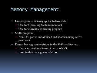
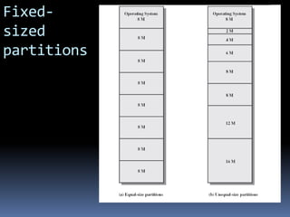
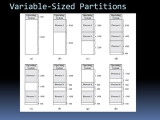
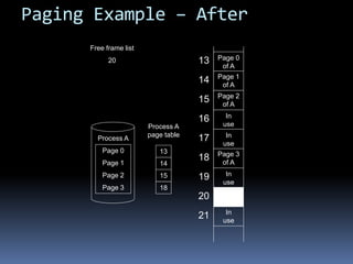
COMPUTER ARCHITECTURE
MEMORY MANAGEMENT
Mr.Mohan S.Sonale
SITCOE,Yadrav
Course Outcomes
 Distinguish the organization of various parts of a system
memory hierarchy
 learn how computing systems are structured in the
processor memory management , cache etc.
Memory Management
 Uni-program – memory split into two parts
 One for Operating System (monitor)
 One for currently executing program
 Multi-program
 Non-O/S part is sub-divided and shared among active
processes
 Remember segment registers in the 8086 architecture
 Hardware designed to meet needs of O/S
 Base Address = segment address
Swapping
 Problem: I/O (Printing, Network, Keyboard, etc.) is so slow
compared with CPU that even in multi-programming system, CPU
can be idle most of the time
 Solutions:
 Increase main memory
 Expensive
 Programmers will eventually use all of this memory for a
single process
 Swapping
What is Swapping?
 Long term queue of processes stored on disk
 Processes “swapped” in as space becomes available
 As a process completes it is moved out of main memory
 If none of the processes in memory are ready (i.e. all I/O blocked)
 Swap out a blocked process to intermediate queue
 Swap in a ready process or a new process
 But swapping is an I/O process!
 It could make the situation worse
 Disk I/O is typically fastest of all, so it still is an improvement
Partitioning
 Splitting memory into sections to allocate to processes
(including Operating System)
 Two types
 Fixed-sized partitions
 Variable-sized partitions
Fixed-Sized Partitions
(continued)
 Equal size or Unequal size partitions
 Process is fitted into smallest hole that will take it (best fit)
 Some wasted memory due to each block having a hole of
unused memory at the end of its partition
 Leads to variable sized partitions
Fixed-
sized
partitions
Variable-Sized Partitions
 Allocate exactly the required memory to a process
 This leads to a hole at the end of memory, too small to use – Only one
small hole - less waste
 When all processes are blocked, swap out a process and bring in another
 New process may be smaller than swapped out process
 Reloaded process not likely to return to same place in memory it started
in
 Another hole
 Eventually have lots of holes (fragmentation)
Variable-Sized Partitions
Solutions to Holes in Variable-
Sized Partitions
 Coalesce - Join adjacent holes into a single large hole
 Compaction - From time to time go through memory and move
all holes into one free block (c.f. disk de-fragmentation)
Paging (continued)
 Split memory into equal sized, small chunks -page frames
 Split programs (processes) into equal sized small chunks –
pages
 Allocate the required number page frames to a process
 Operating System maintains list of free frames
 A process does not require contiguous page frames
Paging (continued)
 Use page table to keep track of how the process is distributed
through the pages in memory
 Now addressing becomes page number:relative address within
page which is mapped to frame number:relative address within
frame.
Paging (continued)
Paging Example – Before
Process A
Page 0
Page 1
Page 2
Page 3
13
14
15
16
17
18
19
20
21
Free frame list
13
14
15
18
20
In
use
In
use
In
use
In
use
Paging Example – After
Process A
Page 0
Page 1
Page 2
Page 3
Free frame list
20
Process A
page table
13
14
15
18
13
14
15
16
17
18
19
20
21
In
use
In
use
In
use
In
use
Page 0
of A
Page 1
of A
Page 2
of A
Page 3
of A
Virtual Memory
 Remember the Principle of Locality which states that “active”
code tends to cluster together, and if a memory item is used
once, it will most likely be used again.
 Demand paging
 Do not require all pages of a process in memory
 Bring in pages as required
Page Fault in Virtual Memory
 Required page is not in memory
 Operating System must swap in required page
 May need to swap out a page to make space
 Select page to throw out based on recent history
Virtual Memory Bonus
 We do not need all of a process in memory for it to run
 We can swap in pages as required
 So - we can now run processes that are bigger than total
memory available!
 Main memory is called real memory
 User/programmer sees much bigger memory - virtual memory
Thrashing
 Too many processes in too little memory
 Operating System spends all its time swapping
 Little or no real work is done
 Disk light is on all the time
 Solutions
 Better page replacement algorithms
 Reduce number of processes running
 Get more memory
Segmentation
 Paging is not (usually) visible to the programmer
 Segmentation is visible to the programmer
 Usually different segments allocated to program and data
 There may be a number of program and data segments
 Segmentation partitions memory
Advantages of Segmentation
 Simplifies handling of growing data structures – O/S will
expand or contract the segment as needed
 Allows programs to be altered and recompiled independently,
without re-linking and re-loading
 Lends itself to sharing among processes
 Lends itself to protection since O/S can specify certain
privileges on a segment-by-segment basis
 Some systems combine segmentation with paging
CACHE MEMORY PRINCIPLES
 Cache memory is intended to give memory speed
approaching that of the fastest memories available, and at
the same time provide a large memory size at the price of
less expensive types of semiconductor memories.

 Single Cache Memory
 The concept is illustrated in Figure 4.3a. There is a relatively large
and slow main memory together with a smaller, faster cache
memory. The cache contains a copy of portions of main memory.
When the processor attempts to read a word of memory, a check is
made to determine if the word is in the cache If so, the word is
delivered to the processor. If not, a block of main memory,
consisting of some fixed number of words, is read into the cache
and then the word is delivered to the processor
The L2 cache is slower and typicallylarger than the L1 cache,and the L3
cache is slower and typicallylarger than the L2 cache.
Structure of Main Memory & Cache Memory
 Main memory consists of up to 2n addressable words, with each word
having a unique n-bit address.
 For mapping purposes, this memory is considered to consist of a
number of fixed length blocks of K words each. That is, there are M
2n/K blocks in main memory.
 The cache consists of m blocks, called lines. Each line contains K
words, plus a tag of a few bits. Each line also includes control bits (not
shown), such as a bit to indicate whether the line has been modified
since being loaded into the cache.
 The length of a line, not including tag and control bits, is the line size
Cache Design
 Addressing
 Size
 Mapping Function
 Replacement Algorithm
 Write Policy
 Block Size
 Number of Caches
Addressing
 When virtual memory is used, the address fields of machine
instructions contain virtual addresses. For reads to and writes from
main memory, a hardware memory management unit (MMU)
translates each virtual address into a physical address in main
memory.
 When virtual addresses are used, the system designer may choose to
place the cache between the processor and the MMU or between the
MMU and main memory (Figure 4.7). A logical cache, also known as
a virtual cache, stores data
 using virtual addresses.
 The processor accesses the cache directly, without going
 through the MMU. A physical cache stores data using main memory
physical addresses.
Processor Type
Year of
Introduction
L1 cache L2 cache L3 cache
IBM 360/85 Mainframe 1968 16 to 32 KB — —
PDP-11/70 Minicomputer 1975 1 KB — —
VAX 11/780 Minicomputer 1978 16 KB — —
IBM 3033 Mainframe 1978 64 KB — —
IBM 3090 Mainframe 1985 128 to 256 KB — —
Intel 80486 PC 1989 8 KB — —
Pentium PC 1993 8 KB/8 KB 256 to 512 KB —
PowerPC 601 PC 1993 32 KB — —
PowerPC 620 PC 1996 32 KB/32 KB — —
PowerPC G4 PC/server 1999 32 KB/32 KB 256 KB to 1 MB 2 MB
IBM S/390 G4 Mainframe 1997 32 KB 256 KB 2 MB
IBM S/390 G6 Mainframe 1999 256 KB 8 MB —
Pentium 4 PC/server 2000 8 KB/8 KB 256 KB —
IBM SP
High-end server/
supercomputer
2000 64 KB/32 KB 8 MB —
CRAY MTAb Supercomputer 2000 8 KB 2 MB —
Itanium PC/server 2001 16 KB/16 KB 96 KB 4 MB
SGI Origin 2001 High-end server 2001 32 KB/32 KB 4 MB —
Itanium 2 PC/server 2002 32 KB 256 KB 6 MB
IBM POWER5 High-end server 2003 64 KB 1.9 MB 36 MB
CRAY XD-1 Supercomputer 2004 64 KB/64 KB 1MB —

Memory comp

  • 1.
  • 2.
    Course Outcomes  Distinguishthe organization of various parts of a system memory hierarchy  learn how computing systems are structured in the processor memory management , cache etc.
  • 3.
    Memory Management  Uni-program– memory split into two parts  One for Operating System (monitor)  One for currently executing program  Multi-program  Non-O/S part is sub-divided and shared among active processes  Remember segment registers in the 8086 architecture  Hardware designed to meet needs of O/S  Base Address = segment address
  • 4.
    Swapping  Problem: I/O(Printing, Network, Keyboard, etc.) is so slow compared with CPU that even in multi-programming system, CPU can be idle most of the time  Solutions:  Increase main memory  Expensive  Programmers will eventually use all of this memory for a single process  Swapping
  • 5.
    What is Swapping? Long term queue of processes stored on disk  Processes “swapped” in as space becomes available  As a process completes it is moved out of main memory  If none of the processes in memory are ready (i.e. all I/O blocked)  Swap out a blocked process to intermediate queue  Swap in a ready process or a new process  But swapping is an I/O process!  It could make the situation worse  Disk I/O is typically fastest of all, so it still is an improvement
  • 6.
    Partitioning  Splitting memoryinto sections to allocate to processes (including Operating System)  Two types  Fixed-sized partitions  Variable-sized partitions
  • 7.
    Fixed-Sized Partitions (continued)  Equalsize or Unequal size partitions  Process is fitted into smallest hole that will take it (best fit)  Some wasted memory due to each block having a hole of unused memory at the end of its partition  Leads to variable sized partitions
  • 8.
  • 9.
    Variable-Sized Partitions  Allocateexactly the required memory to a process  This leads to a hole at the end of memory, too small to use – Only one small hole - less waste  When all processes are blocked, swap out a process and bring in another  New process may be smaller than swapped out process  Reloaded process not likely to return to same place in memory it started in  Another hole  Eventually have lots of holes (fragmentation)
  • 10.
  • 11.
    Solutions to Holesin Variable- Sized Partitions  Coalesce - Join adjacent holes into a single large hole  Compaction - From time to time go through memory and move all holes into one free block (c.f. disk de-fragmentation)
  • 12.
    Paging (continued)  Splitmemory into equal sized, small chunks -page frames  Split programs (processes) into equal sized small chunks – pages  Allocate the required number page frames to a process  Operating System maintains list of free frames  A process does not require contiguous page frames
  • 13.
    Paging (continued)  Usepage table to keep track of how the process is distributed through the pages in memory  Now addressing becomes page number:relative address within page which is mapped to frame number:relative address within frame.
  • 14.
  • 15.
    Paging Example –Before Process A Page 0 Page 1 Page 2 Page 3 13 14 15 16 17 18 19 20 21 Free frame list 13 14 15 18 20 In use In use In use In use
  • 16.
    Paging Example –After Process A Page 0 Page 1 Page 2 Page 3 Free frame list 20 Process A page table 13 14 15 18 13 14 15 16 17 18 19 20 21 In use In use In use In use Page 0 of A Page 1 of A Page 2 of A Page 3 of A
  • 17.
    Virtual Memory  Rememberthe Principle of Locality which states that “active” code tends to cluster together, and if a memory item is used once, it will most likely be used again.  Demand paging  Do not require all pages of a process in memory  Bring in pages as required
  • 18.
    Page Fault inVirtual Memory  Required page is not in memory  Operating System must swap in required page  May need to swap out a page to make space  Select page to throw out based on recent history
  • 19.
    Virtual Memory Bonus We do not need all of a process in memory for it to run  We can swap in pages as required  So - we can now run processes that are bigger than total memory available!  Main memory is called real memory  User/programmer sees much bigger memory - virtual memory
  • 20.
    Thrashing  Too manyprocesses in too little memory  Operating System spends all its time swapping  Little or no real work is done  Disk light is on all the time  Solutions  Better page replacement algorithms  Reduce number of processes running  Get more memory
  • 21.
    Segmentation  Paging isnot (usually) visible to the programmer  Segmentation is visible to the programmer  Usually different segments allocated to program and data  There may be a number of program and data segments  Segmentation partitions memory
  • 22.
    Advantages of Segmentation Simplifies handling of growing data structures – O/S will expand or contract the segment as needed  Allows programs to be altered and recompiled independently, without re-linking and re-loading  Lends itself to sharing among processes  Lends itself to protection since O/S can specify certain privileges on a segment-by-segment basis  Some systems combine segmentation with paging
  • 23.
    CACHE MEMORY PRINCIPLES Cache memory is intended to give memory speed approaching that of the fastest memories available, and at the same time provide a large memory size at the price of less expensive types of semiconductor memories. 
  • 24.
     Single CacheMemory  The concept is illustrated in Figure 4.3a. There is a relatively large and slow main memory together with a smaller, faster cache memory. The cache contains a copy of portions of main memory. When the processor attempts to read a word of memory, a check is made to determine if the word is in the cache If so, the word is delivered to the processor. If not, a block of main memory, consisting of some fixed number of words, is read into the cache and then the word is delivered to the processor
  • 25.
    The L2 cacheis slower and typicallylarger than the L1 cache,and the L3 cache is slower and typicallylarger than the L2 cache.
  • 26.
    Structure of MainMemory & Cache Memory  Main memory consists of up to 2n addressable words, with each word having a unique n-bit address.  For mapping purposes, this memory is considered to consist of a number of fixed length blocks of K words each. That is, there are M 2n/K blocks in main memory.  The cache consists of m blocks, called lines. Each line contains K words, plus a tag of a few bits. Each line also includes control bits (not shown), such as a bit to indicate whether the line has been modified since being loaded into the cache.  The length of a line, not including tag and control bits, is the line size
  • 28.
    Cache Design  Addressing Size  Mapping Function  Replacement Algorithm  Write Policy  Block Size  Number of Caches
  • 29.
    Addressing  When virtualmemory is used, the address fields of machine instructions contain virtual addresses. For reads to and writes from main memory, a hardware memory management unit (MMU) translates each virtual address into a physical address in main memory.  When virtual addresses are used, the system designer may choose to place the cache between the processor and the MMU or between the MMU and main memory (Figure 4.7). A logical cache, also known as a virtual cache, stores data  using virtual addresses.  The processor accesses the cache directly, without going  through the MMU. A physical cache stores data using main memory physical addresses.
  • 31.
    Processor Type Year of Introduction L1cache L2 cache L3 cache IBM 360/85 Mainframe 1968 16 to 32 KB — — PDP-11/70 Minicomputer 1975 1 KB — — VAX 11/780 Minicomputer 1978 16 KB — — IBM 3033 Mainframe 1978 64 KB — — IBM 3090 Mainframe 1985 128 to 256 KB — — Intel 80486 PC 1989 8 KB — — Pentium PC 1993 8 KB/8 KB 256 to 512 KB — PowerPC 601 PC 1993 32 KB — — PowerPC 620 PC 1996 32 KB/32 KB — — PowerPC G4 PC/server 1999 32 KB/32 KB 256 KB to 1 MB 2 MB IBM S/390 G4 Mainframe 1997 32 KB 256 KB 2 MB IBM S/390 G6 Mainframe 1999 256 KB 8 MB — Pentium 4 PC/server 2000 8 KB/8 KB 256 KB — IBM SP High-end server/ supercomputer 2000 64 KB/32 KB 8 MB — CRAY MTAb Supercomputer 2000 8 KB 2 MB — Itanium PC/server 2001 16 KB/16 KB 96 KB 4 MB SGI Origin 2001 High-end server 2001 32 KB/32 KB 4 MB — Itanium 2 PC/server 2002 32 KB 256 KB 6 MB IBM POWER5 High-end server 2003 64 KB 1.9 MB 36 MB CRAY XD-1 Supercomputer 2004 64 KB/64 KB 1MB —