This document provides an overview of microprocessors, specifically focusing on the 8086 microprocessor architecture, its components, and functionalities. It discusses the evolution and categorization of microprocessors, instruction types, addressing modes, and the role of various registers including the execution unit and bus interface unit. Key elements such as control and status flags, along with the instruction set, are also elaborated on for a comprehensive understanding of the 8086 microprocessor.
![Direct addressing mode:
• In the direct addressing mode, a 16-bit memory address (offset) directly
specified in the instruction as a part of it.
Example: MOV AX, [5000H].
Register addressing mode:
25
• In the register addressing mode, the data is stored in a register and it is
referred using the particular register. All the registers, except IP,
used in this mode.
may be
Example: MOV BX, AX
Addressing Modes of
8086](https://image.slidesharecdn.com/mpmcpptmodule12jan2024-240722175546-ece0c65f/75/MPMC-PPT_MODULE-1-2-Jan202mmmmmmmmmmm4-pdf-25-2048.jpg)
![Register indirect addressing mode:
• Sometimes, the address of the memory location which contains data or
operands is determined in an indirect way, using the offset registers. The
mode of addressing is known as register indirect mode.
• In this addressing mode, the offset address of data is in either BX or SI or
DI Register. The default segment is either DS or ES.
E•
xample: MOV AX, [BX].
26
Addressing Modes of
8086](https://image.slidesharecdn.com/mpmcpptmodule12jan2024-240722175546-ece0c65f/75/MPMC-PPT_MODULE-1-2-Jan202mmmmmmmmmmm4-pdf-26-2048.jpg)
![Indexed addressing mode:
• In this addressing mode, offset of the operand is stored one of the index
registers. DS & ES are the default segments for index registers SI & DI
respectively.
Example: MOV AX, [SI]
• Here, data is available at an offset address stored in SI in DS.
27
Addressing Modes of
8086](https://image.slidesharecdn.com/mpmcpptmodule12jan2024-240722175546-ece0c65f/75/MPMC-PPT_MODULE-1-2-Jan202mmmmmmmmmmm4-pdf-27-2048.jpg)
![Register relative addressing mode:
• In this addressing mode, the data is available at an effective address formed
by adding an 8-bit or 16-bit displacement with the content of any one of
the register BX, BP, SI & DI in the default (either in DS & ES) segment.
28
Example: MOV AX, 50H [BX]
Addressing Modes of
8086](https://image.slidesharecdn.com/mpmcpptmodule12jan2024-240722175546-ece0c65f/75/MPMC-PPT_MODULE-1-2-Jan202mmmmmmmmmmm4-pdf-28-2048.jpg)
![•
29
•
Based indexed addressing mode:
• The effective address of data is formed in this addressing mode, by
adding content of a base register (any one of BX or BP) to the
content of an index register (any one of SI or DI). The default
segment register may be ES or DS. Example: MOV AX, [BX][SI]
Relative based indexed:
• The effective address is formed by adding an 8 or 16-bit displacement with
the sum of contents of any of the base registers (BX or BP) and any one
of the index registers, in a default segment.
Example: MOV AX, 50H [BX] [SI]
•
Addressing Modes of
8086](https://image.slidesharecdn.com/mpmcpptmodule12jan2024-240722175546-ece0c65f/75/MPMC-PPT_MODULE-1-2-Jan202mmmmmmmmmmm4-pdf-29-2048.jpg)
![Intersegment indirect:
In this mode, the address to which the control is to be transferred lies in a
different segment and it is passed to the instruction indirectly, i.e. contents
of a memory block containing four bytes, i.e. IP(LSB), IP(MSB), CS(LSB) and
CS(MSB) sequentially. The starting address of the memory block may be
referred using any of the addressing modes, except immediate mode.
Example: JMP [2000H].
32
Jump to an address in the other segment specified at effective
2000H in DS.
address
Modes of
8086](https://image.slidesharecdn.com/mpmcpptmodule12jan2024-240722175546-ece0c65f/75/MPMC-PPT_MODULE-1-2-Jan202mmmmmmmmmmm4-pdf-32-2048.jpg)
![• Intrasegment indirect mode:
• In this mode, the displacement to which the control is to be transferred is
in the same segment in which the control transfer instruction lies, but it is
passed to the instruction directly. Here, the branch address is found as the
content of a register or a memory location.
• This addressing mode may be used in unconditional branch
instructions.
• Example: JMP [BX]; Jump to effective address stored in BX.
35
Addressing
Modes](https://image.slidesharecdn.com/mpmcpptmodule12jan2024-240722175546-ece0c65f/75/MPMC-PPT_MODULE-1-2-Jan202mmmmmmmmmmm4-pdf-35-2048.jpg)
![• The contents of different registers are given below. Form the effective or
physical address of the following instructions
• [AX]=1000H, [BX]=2000H, [SI]=3000H, [DI]=4000H, [BP]=5000H,
[SP]=6000H, [CS]= 0000H, [DS]= 1000H, [SS]= 2000H, [ES]=3000H,
[IP]=7000H
• 1. MOV AX, [5000H]
• 2. MOV AX, [BP]
• 3. MOV AX, 5000[BX]
• 4. MOV AX, [BX][SI]
• 5. MOV AX, 5000[BX][SI]
• 6. MOV AX, [DI]
36
Addressing
Modes](https://image.slidesharecdn.com/mpmcpptmodule12jan2024-240722175546-ece0c65f/75/MPMC-PPT_MODULE-1-2-Jan202mmmmmmmmmmm4-pdf-36-2048.jpg)
![General Form:
• MOV destination, source
• Here the source and destination needs to be of the same size, that
is both 8 bit or both 16 bit.
• MOV instruction does not affect any flags.
Example:-
39
•
• MOV BX,
00F2H;
load the immediate number 00F2H
in BX register
• MOV CL, [2000H] ;Copy the 8 bit content of the
memory
location, at a
displacement of2000H
from data segment base to the CL register
Data Transfer instructions](https://image.slidesharecdn.com/mpmcpptmodule12jan2024-240722175546-ece0c65f/75/MPMC-PPT_MODULE-1-2-Jan202mmmmmmmmmmm4-pdf-39-2048.jpg)
![•MOV [589H], BX; Copy the 16 bit content of BX register on to the
memory location, which at a
displacement of 589H from the data segment
base.
• MOV DS, CX; Move the content of CX to DS
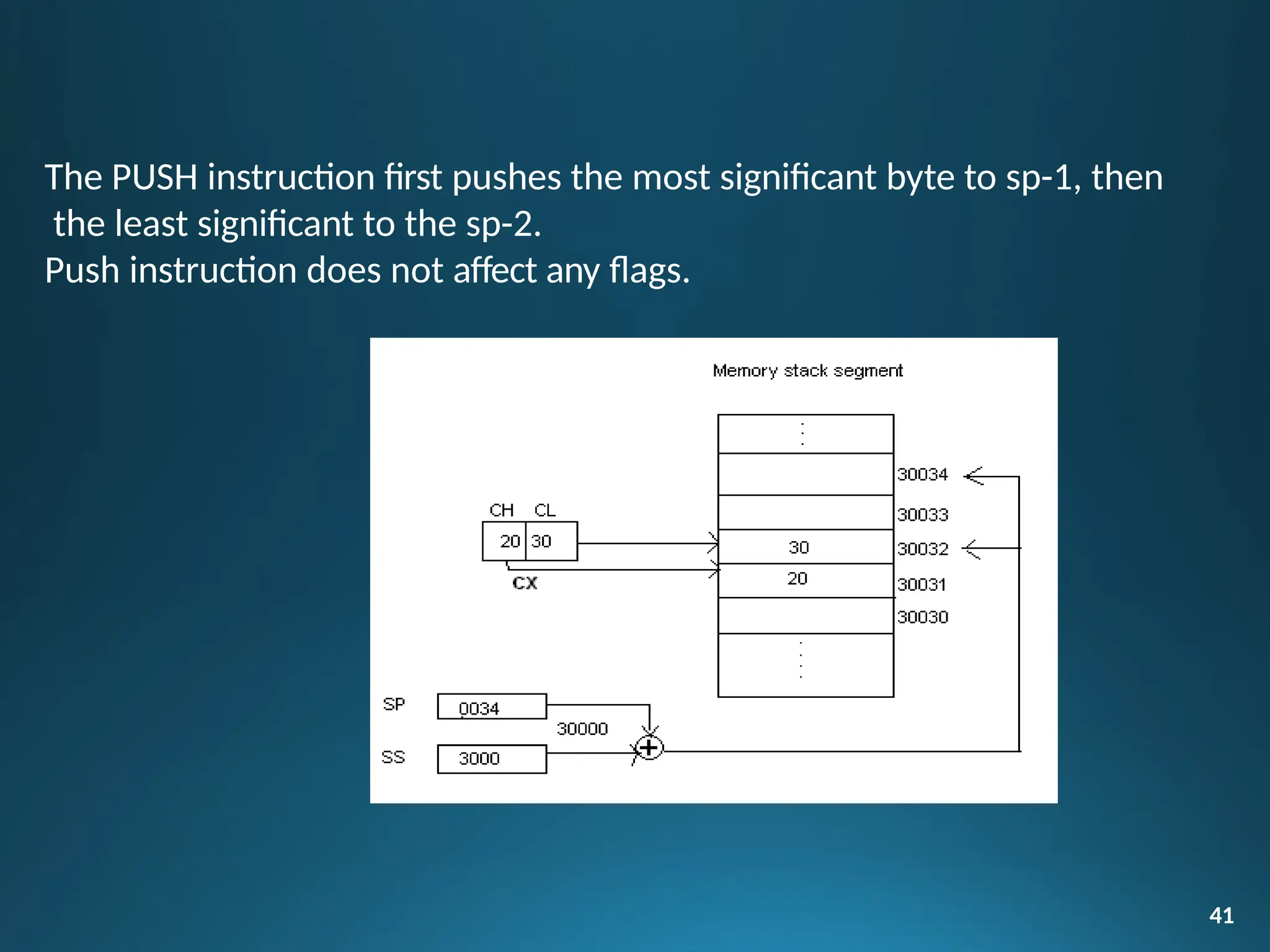
PUSH instruction
• The PUSH instruction decrements the stack pointer by two and
copies the word from source to the location where stack pointer
now points. Here the source must of word size data. Source can be
a general purpose register, segment register or a memory location.
40](https://image.slidesharecdn.com/mpmcpptmodule12jan2024-240722175546-ece0c65f/75/MPMC-PPT_MODULE-1-2-Jan202mmmmmmmmmmm4-pdf-40-2048.jpg)
![XCHG instruction
• The XCHG instruction exchanges contents of the destination and
source. Here destination and source can be register and register or
register and memory location, but XCHG cannot interchange the
value of 2 memory locations.
General Format
• XCHG Destination, Source
Example:
• XCHG BX, CX; exchange word in CX with the word in BX
• XCHG AL, CL; exchange byte in CL with the byte in AL
• XCHG AX, SUM[BX];here physical address, which is DS+SUM+[BX].
The content at physical
address and the content of AX are interchanged.
44](https://image.slidesharecdn.com/mpmcpptmodule12jan2024-240722175546-ece0c65f/75/MPMC-PPT_MODULE-1-2-Jan202mmmmmmmmmmm4-pdf-44-2048.jpg)
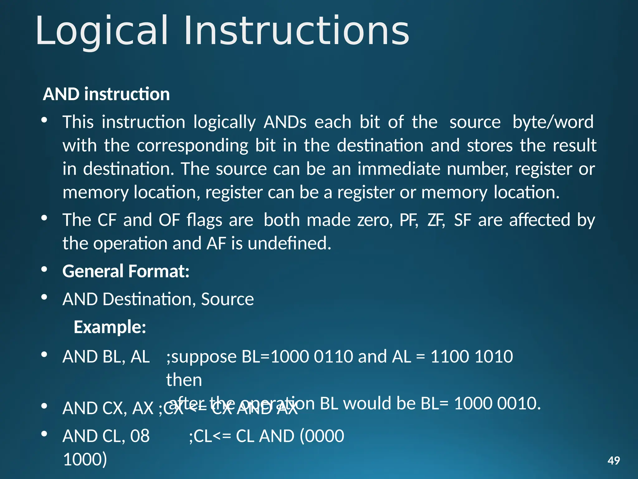
![Example:
• OR BL, AL; suppose BL=1000 0110 and AL = 1100 1010 then
after the operation BL would be BL= 1100 1110.
• OR CX, AX;CX <= CX AND AX
• OR CL, 08;CL<= CL AND (0000 1000)
NOT instruction
• The NOT instruction complements (inverts) the contents of an
operand register or a memory location, bit by bit. The examples are
as follows:
Example:
• NOT AX (BEFORE AX= (1011)2= (B) 16 AFTER EXECUTION AX=
(0100)2= (4)16).
• NOT [5000H]
51](https://image.slidesharecdn.com/mpmcpptmodule12jan2024-240722175546-ece0c65f/75/MPMC-PPT_MODULE-1-2-Jan202mmmmmmmmmmm4-pdf-51-2048.jpg)
![XOR instruction
• The XOR operation is again carried out in a similar way to the AND
and OR operation. The constraints on the operands are also similar.
The XOR operation gives a high output, when the 2 input bits are
dissimilar. Otherwise, the output is zero. The example instructions
are as follows:
Example:
• XOR AX,0098H
• XOR AX,BX
• XOR AX,[5000H]
52](https://image.slidesharecdn.com/mpmcpptmodule12jan2024-240722175546-ece0c65f/75/MPMC-PPT_MODULE-1-2-Jan202mmmmmmmmmmm4-pdf-52-2048.jpg)
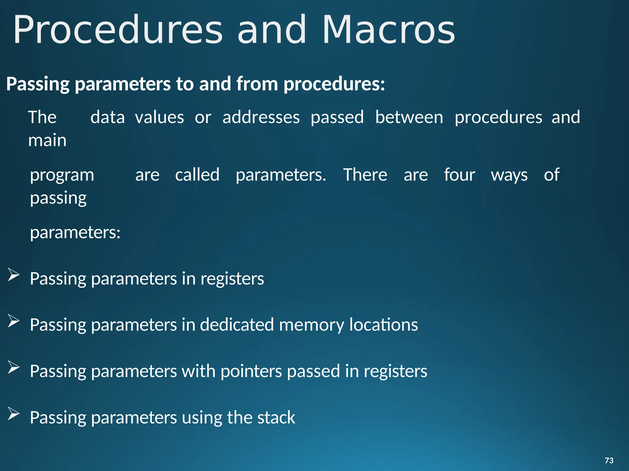
![Procedures:
• While writing programs, it may be the case that a particular sequence of
instructions is used several times. To avoid writing the sequence of
instructions again and again in the program, the same sequence can be
written as a separate subprogram called a procedure.
Defining Procedures:
72
• Assembler provides PROC and ENDP directives in order to
define
procedures. The directive PROC indicates beginning of a procedure.
Its general form is:
Procedure_name PROC [NEAR|FAR]
Procedures and Macros](https://image.slidesharecdn.com/mpmcpptmodule12jan2024-240722175546-ece0c65f/75/MPMC-PPT_MODULE-1-2-Jan202mmmmmmmmmmm4-pdf-72-2048.jpg)