Downloaded 402 times

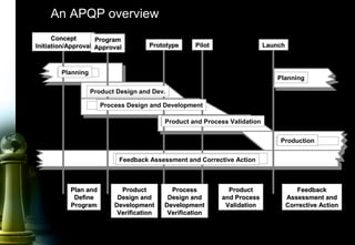


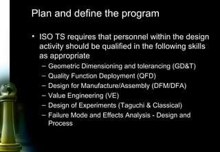
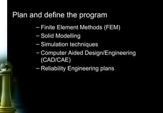


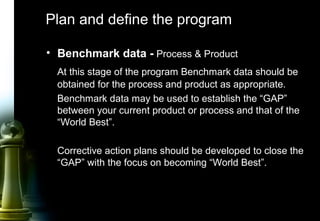


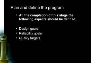
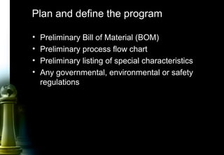

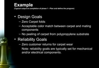


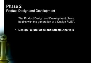

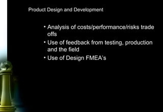
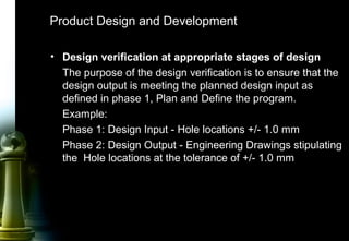


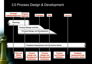


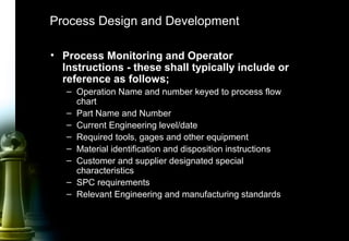

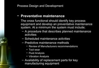

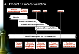


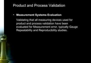


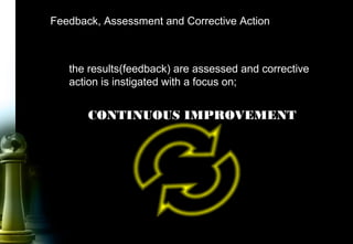
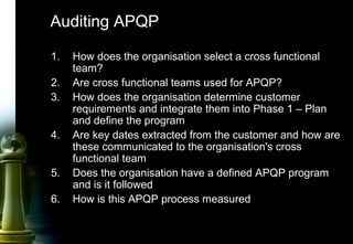


The document provides information on Advanced Product Quality Planning (APQP) and its 5 phases: 1) Plan and Define Program, 2) Product Design and Development, 3) Process Design and Development, 4) Product and Process Validation, and 5) Feedback, Assessment and Corrective Action. It describes the objectives and key activities that should be completed in each phase of the APQP process.


![MM Bagali, PhD, HRM, HRD, Communication [Compatibility Mode]](https://cdn.slidesharecdn.com/ss_thumbnails/communicationcompatibilitymode-13303152725586-phpapp02-120226220305-phpapp02-thumbnail.jpg?width=640&height=640&fit=bounds)


![Apqp+english+version[1]](https://cdn.slidesharecdn.com/ss_thumbnails/apqpenglishversion1-121219073626-phpapp02-thumbnail.jpg?width=640&height=640&fit=bounds)


