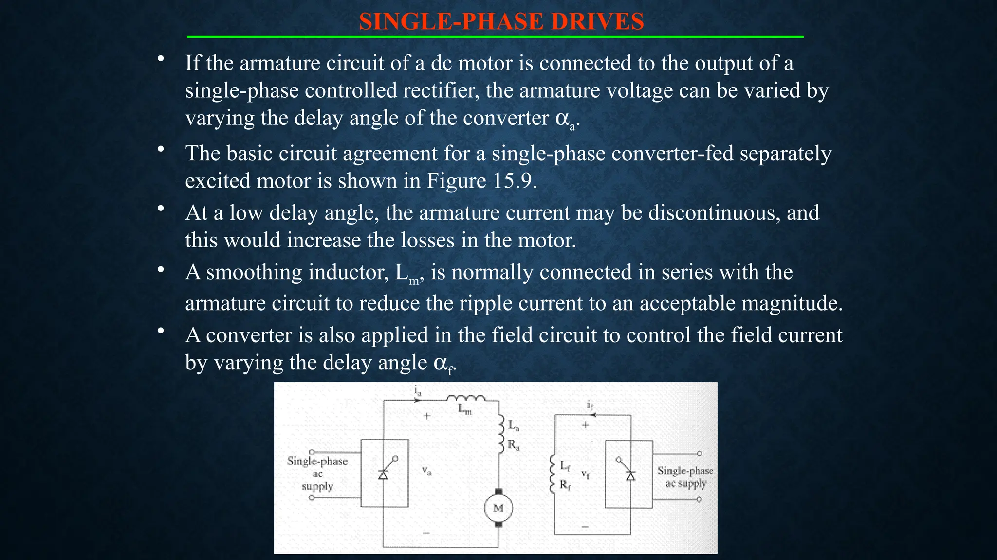
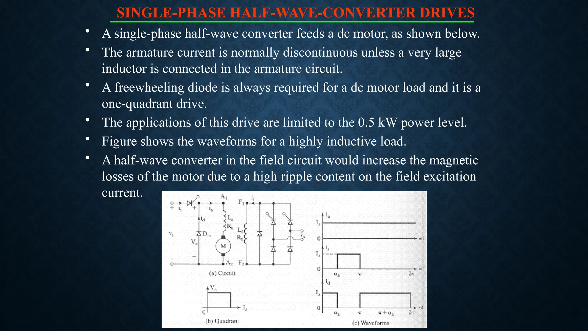
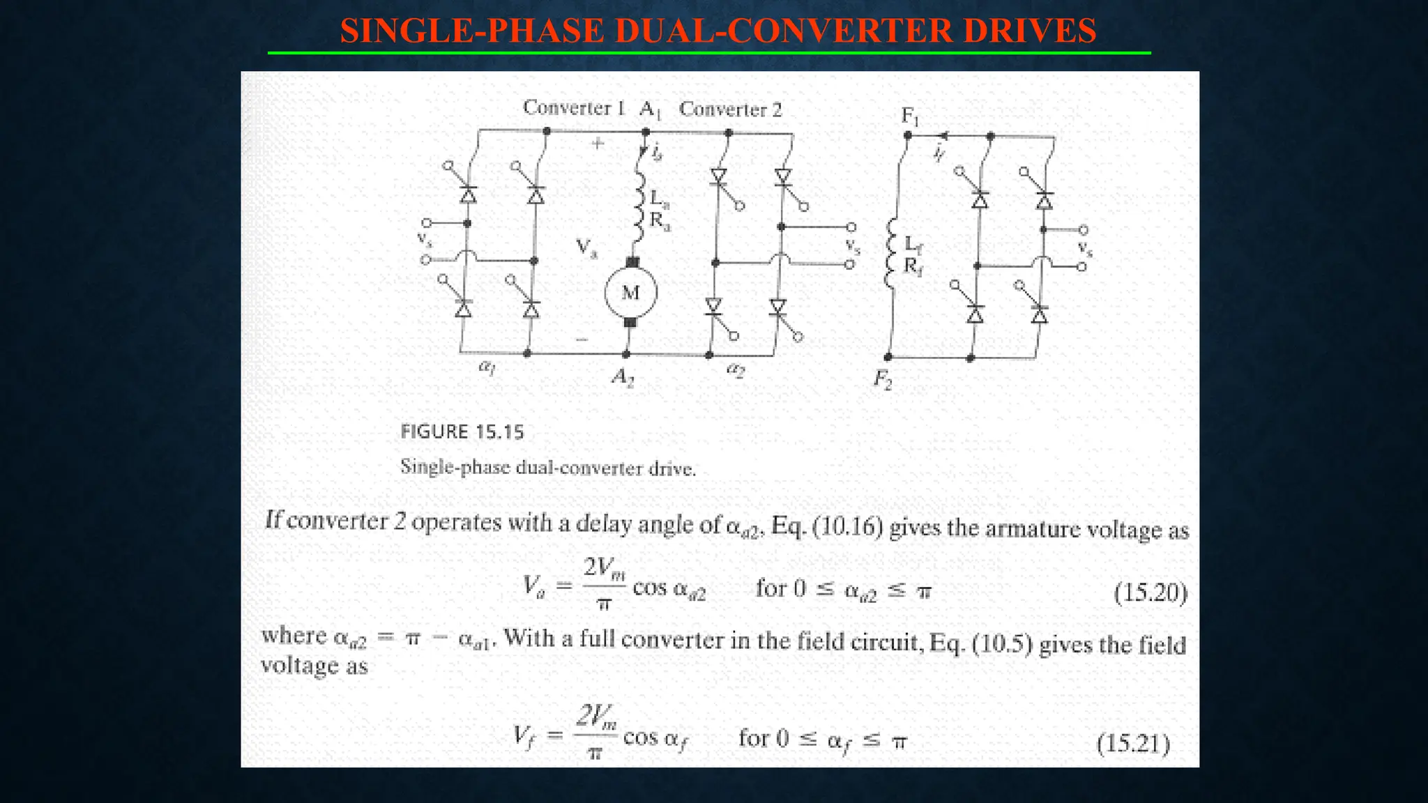
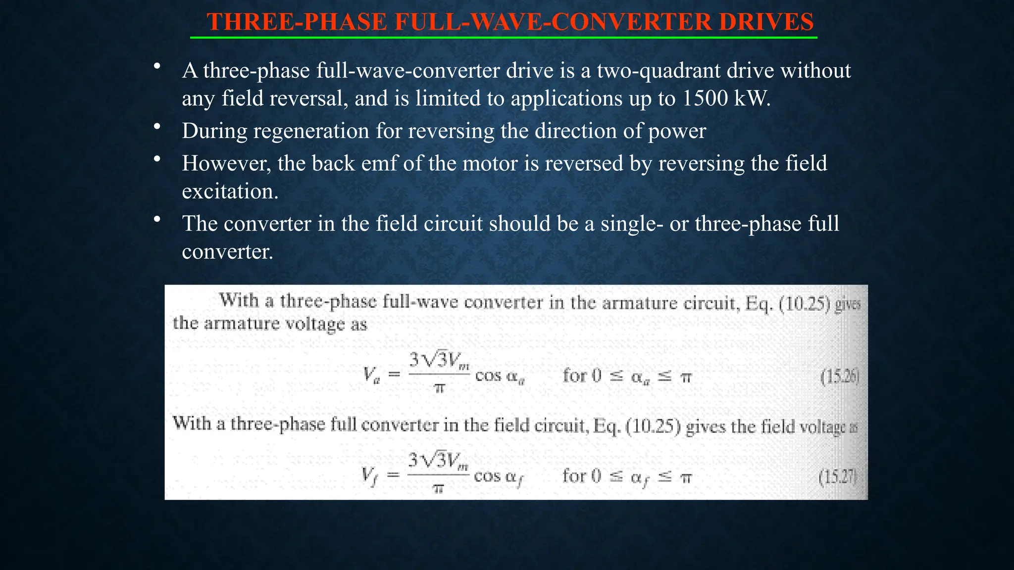
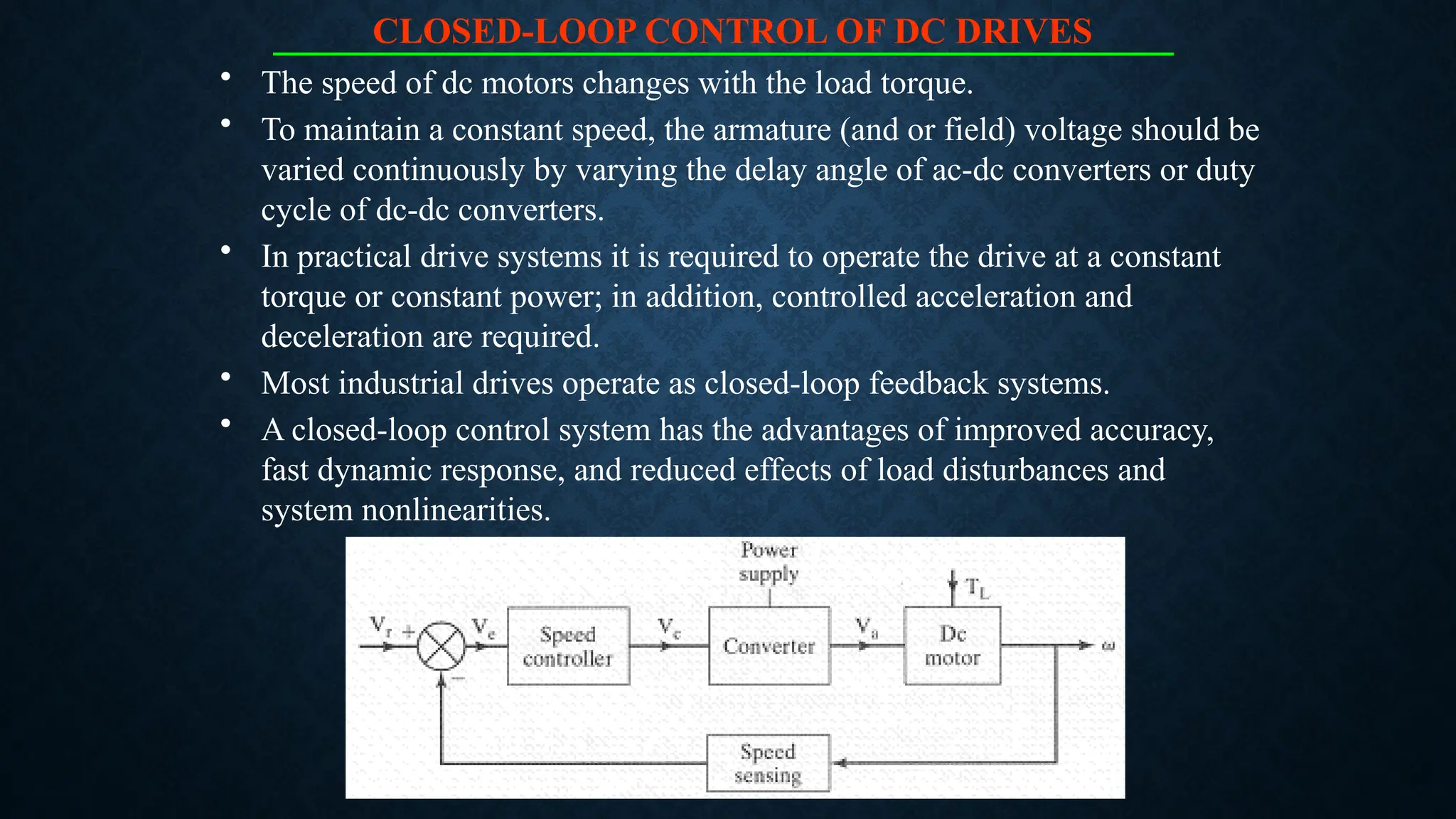
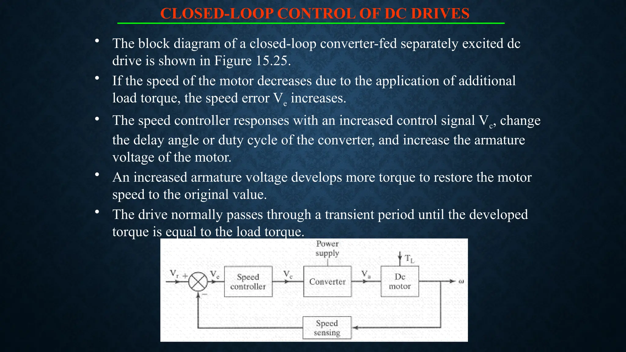
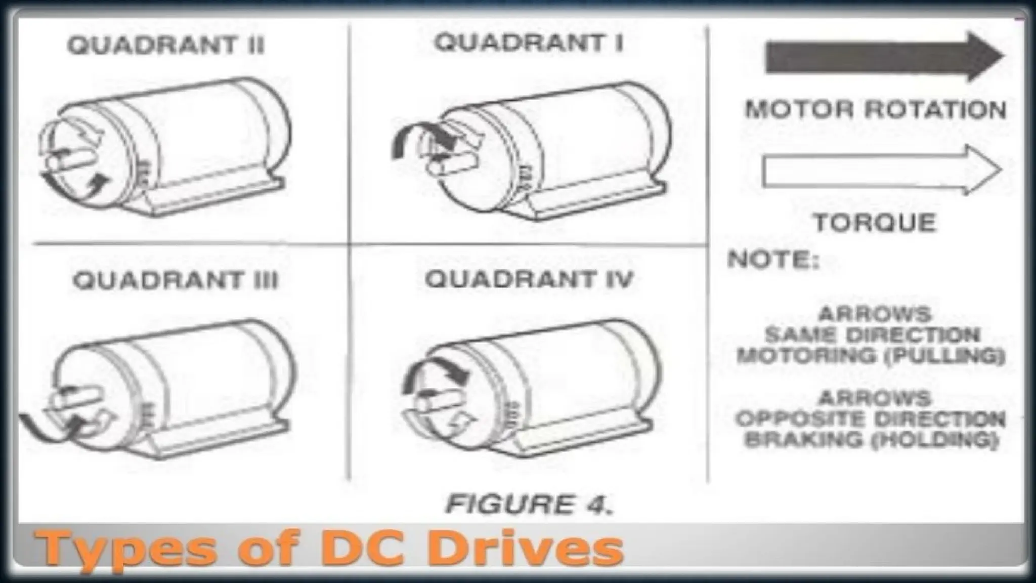
Asmarya Islamic University
Faculty of Engineering
Name: Ali Salem Al-kout 219080242
D.r: Suleiman bin Rahama
The report: DC Drives
What is Drive?
Drive used for the control of electric motors speed.
AC drive used for the controlling of Ac motor speed
while DC drives used for DC motors.
AC drive is also called {Variable Frequency Drive}
Direct current (dc) motors have variable characteristics and are used extensively in variable-speed drives.
DC motors can provide a high starting torque and it is also possible to obtain speed control over a wide
range.
The methods of speed control are normally simpler and less expensive than those of AC drives.
DC motors play a significant role in modern industrial drives.
Both series and separately excited DC motors are normally used in variable-speed drives, but series
motors are traditionally employed for traction applications.
Due to commutators, DC motors are not suitable for very high speed applications and require more
maintenance than do AC motors.
With the recent advancements in power conversions, control techniques, and microcomputers, the ac
motor drives are becoming increasingly competitive with DC motor drives.
Although the future trend is toward AC drives, DC drives are currently used in many industries. It
might be a few decades before the DC drives are completely replaced by AC drives.
Introduction: DC Motor Drives
• Controlled rectifiers provide a variable dc output voltage from a fixed ac voltage, whereas a dc-dc
converter can provide a variable dc voltage from a fixed dc voltage.
• Due to their ability to supply a continuously variable dc voltage, controlled rectifiers and dc-dc
converters made a revolution in modern industrial control equipment and variable-speed drives, with
power levels ranging from fractional horsepower to several megawatts.
• Controlled rectifiers are generally used for the speed control of dc motors.
• The alternative form would be a diode rectifier followed by dc-dc converter.
• DC drives can be classified, in general, into three types:
– 1. Single-phase drives
– 2. Three-phase drives
– 3. DC-DC converter drives
Introduction: DC Motor Drives
SINGLE-PHASE DRIVES
• If the armature circuit of a dc motor is connected to the output of a
single-phase controlled rectifier, the armature voltage can be varied by
varying the delay angle of the converter aa.
• The basic circuit agreement for a single-phase converter-fed separately
excited motor is shown in Figure 15.9.
• At a low delay angle, the armature current may be discontinuous, and
this would increase the losses in the motor.
• A smoothing inductor, Lm, is normally connected in series with the
armature circuit to reduce the ripple current to an acceptable magnitude.
• A converter is also applied in the field circuit to control the field current
by varying the delay angle af.
SINGLE-PHASE DRIVES
• Depending on the type of single-phase converters,
– single-phase drives may be subdivided into:
– Single-phase half-wave-converter drives.
– Single-phase semi converter drives.
– Single-phase full-converter drives.
– Single-phase dual-converter drives.
SINGLE-PHASE HALF-WAVE-CONVERTER DRIVES
• A single-phase half-wave converter feeds a dc motor, as shown below.
• The armature current is normally discontinuous unless a very large
inductor is connected in the armature circuit.
• A freewheeling diode is always required for a dc motor load and it is a
one-quadrant drive.
• The applications of this drive are limited to the 0.5 kW power level.
• Figure shows the waveforms for a highly inductive load.
• A half-wave converter in the field circuit would increase the magnetic
losses of the motor due to a high ripple content on the field excitation
current.
SINGLE-PHASE HALF-WAVE-CONVERTER DRIVES
SINGLE-PHASE FULL-WAVE-CONVERTER DRIVES
• The armature voltage is varied by a single-phase full-wave converter, as
shown in Figure 15.13a.
• It is a two-quadrant drive, as shown in Figure 15.13b, and is limited to
applications up to 15 kW.
• The armature converter gives + Va or - Va, and allows operation in the
first and fourth quadrants.
• During regeneration for reversing the direction of power flow, the back
emf of the motor can be reversed by reversing the field excitation.
SINGLE-PHASE FULL-WAVE-CONVERTER DRIVES
• The converter in the field circuit could be a full, or even a dual converter.
• The reversal of the armature or field allows operation in the second and
third quadrants.
• The current waveforms for a highly inductive load are shown in Figure
15.13c for powering action.
SINGLE-PHASE DUAL-CONVERTER DRIVES
• Two single-phase full-wave converters are connected.
• Either converter 1 operates to supply a positive armature voltage, Va, or
converter 2 operates to supply a negative armature voltage, - Va.
• Converter 1 provides operation in the first and fourth quadrants, and
converter 2, in the second and third quadrants.
• It is a four-quadrant drive and permits four modes of operation: forward
powering, forward braking (regeneration), reverse powering, and reverse
braking (regeneration).
• It is limited to applications up to 15 kW. The field converter could be a
full-wave or a dual converter.
SINGLE-PHASE DUAL-CONVERTER DRIVES
THREE-PHASE DRIVES
• The armature circuit is connected to the output of a three-phase
controlled rectifier.
• Three-phase drives are used for high-power applications up to
megawatt power levels.
• The ripple frequency of the armature voltage is higher than that of
single-phase drives and it requires less inductance in the armature
circuit to reduce the armature ripple current.
• The armature current is mostly continuous, and therefore the motor
performance is better compared with that of single-phase drives.
• Similar to the single-phase drives, three-phase drives may also be
subdivided into:
– Three-phase half-wave-converter drives.
– Three-phase semiconverter drives.
– Three-phase full-converter drives.
– Three-phase dual-converter drives.
THREE-PHASE HALF-WAVE-CONVERTER DRIVES
THREE-PHASE FULL-WAVE-CONVERTER DRIVES
• A three-phase full-wave-converter drive is a two-quadrant drive without
any field reversal, and is limited to applications up to 1500 kW.
• During regeneration for reversing the direction of power
• However, the back emf of the motor is reversed by reversing the field
excitation.
• The converter in the field circuit should be a single- or three-phase full
converter.
THREE-PHASE DUAL-CONVERTER DRIVES
• Two three-phase full-wave converters are connected in an arrangement
similar to Figure 15.15a.
• Either converter 1 operates to supply a positive armature voltage, Va or
converter 2 operates to supply a negative armature voltage, -Va.
• It is a four-quadrant drive and is limited to applications up to 1500 kW.
• The field converter can be a full-wave converter.
• If converter 1 operates with a delay angle of
CLOSED-LOOP CONTROL OF DC DRIVES
• The speed of dc motors changes with the load torque.
• To maintain a constant speed, the armature (and or field) voltage should be
varied continuously by varying the delay angle of ac-dc converters or duty
cycle of dc-dc converters.
• In practical drive systems it is required to operate the drive at a constant
torque or constant power; in addition, controlled acceleration and
deceleration are required.
• Most industrial drives operate as closed-loop feedback systems.
• A closed-loop control system has the advantages of improved accuracy,
fast dynamic response, and reduced effects of load disturbances and
system nonlinearities.
CLOSED-LOOP CONTROL OF DC DRIVES
• The block diagram of a closed-loop converter-fed separately excited dc
drive is shown in Figure 15.25.
• If the speed of the motor decreases due to the application of additional
load torque, the speed error Ve increases.
• The speed controller responses with an increased control signal Vc, change
the delay angle or duty cycle of the converter, and increase the armature
voltage of the motor.
• An increased armature voltage develops more torque to restore the motor
speed to the original value.
• The drive normally passes through a transient period until the developed
torque is equal to the load torque.
DC Drives …..Principle of Operation
• A typical adjustable speed drive using a silicon controller rectifier {SCR} power
conversion section.
• The SCR, (also termed a thyristor) converts the fixed voltage alternating current (AC)
of the power source to an adjustable voltage , controlled direct current (DC) output
which is applied to the armature of a DC Motor.
• SCR is provide a controllable power output by “phase angle control ”, so called
because the firing angle (a point in time where the SCR is triggered into conduction)
is synchronized with the phase rotation of AC power source. If the device is triggered
early in half cycle , maximum power is delivered to the motor ; late triggering in the
half cycle provides minimum power.
•
Types of DC Drives
Nonregenerative DC Drives :
Nonregenerative DC drives are the most conventional type in common usage. In
their most basic form they are able to control motor speed and torque in one direction
only.
Regenerative DC Drives :
Regenerative adjustable speed drives, also known as four-quadrant drives, are
capable of controlling not only the speed and direction of motor rotation, but also the
direction of motor torque.
What is dcsr redfffc for the experiment right

What is dcsr redfffc for the experiment right

  • 1.
    Asmarya Islamic University Facultyof Engineering Name: Ali Salem Al-kout 219080242 D.r: Suleiman bin Rahama The report: DC Drives
  • 2.
    What is Drive? Driveused for the control of electric motors speed. AC drive used for the controlling of Ac motor speed while DC drives used for DC motors. AC drive is also called {Variable Frequency Drive}
  • 3.
    Direct current (dc)motors have variable characteristics and are used extensively in variable-speed drives. DC motors can provide a high starting torque and it is also possible to obtain speed control over a wide range. The methods of speed control are normally simpler and less expensive than those of AC drives. DC motors play a significant role in modern industrial drives. Both series and separately excited DC motors are normally used in variable-speed drives, but series motors are traditionally employed for traction applications. Due to commutators, DC motors are not suitable for very high speed applications and require more maintenance than do AC motors. With the recent advancements in power conversions, control techniques, and microcomputers, the ac motor drives are becoming increasingly competitive with DC motor drives. Although the future trend is toward AC drives, DC drives are currently used in many industries. It might be a few decades before the DC drives are completely replaced by AC drives. Introduction: DC Motor Drives
  • 4.
    • Controlled rectifiersprovide a variable dc output voltage from a fixed ac voltage, whereas a dc-dc converter can provide a variable dc voltage from a fixed dc voltage. • Due to their ability to supply a continuously variable dc voltage, controlled rectifiers and dc-dc converters made a revolution in modern industrial control equipment and variable-speed drives, with power levels ranging from fractional horsepower to several megawatts. • Controlled rectifiers are generally used for the speed control of dc motors. • The alternative form would be a diode rectifier followed by dc-dc converter. • DC drives can be classified, in general, into three types: – 1. Single-phase drives – 2. Three-phase drives – 3. DC-DC converter drives Introduction: DC Motor Drives
  • 5.
    SINGLE-PHASE DRIVES • Ifthe armature circuit of a dc motor is connected to the output of a single-phase controlled rectifier, the armature voltage can be varied by varying the delay angle of the converter aa. • The basic circuit agreement for a single-phase converter-fed separately excited motor is shown in Figure 15.9. • At a low delay angle, the armature current may be discontinuous, and this would increase the losses in the motor. • A smoothing inductor, Lm, is normally connected in series with the armature circuit to reduce the ripple current to an acceptable magnitude. • A converter is also applied in the field circuit to control the field current by varying the delay angle af.
  • 6.
    SINGLE-PHASE DRIVES • Dependingon the type of single-phase converters, – single-phase drives may be subdivided into: – Single-phase half-wave-converter drives. – Single-phase semi converter drives. – Single-phase full-converter drives. – Single-phase dual-converter drives.
  • 7.
    SINGLE-PHASE HALF-WAVE-CONVERTER DRIVES •A single-phase half-wave converter feeds a dc motor, as shown below. • The armature current is normally discontinuous unless a very large inductor is connected in the armature circuit. • A freewheeling diode is always required for a dc motor load and it is a one-quadrant drive. • The applications of this drive are limited to the 0.5 kW power level. • Figure shows the waveforms for a highly inductive load. • A half-wave converter in the field circuit would increase the magnetic losses of the motor due to a high ripple content on the field excitation current.
  • 8.
  • 9.
    SINGLE-PHASE FULL-WAVE-CONVERTER DRIVES •The armature voltage is varied by a single-phase full-wave converter, as shown in Figure 15.13a. • It is a two-quadrant drive, as shown in Figure 15.13b, and is limited to applications up to 15 kW. • The armature converter gives + Va or - Va, and allows operation in the first and fourth quadrants. • During regeneration for reversing the direction of power flow, the back emf of the motor can be reversed by reversing the field excitation.
  • 10.
    SINGLE-PHASE FULL-WAVE-CONVERTER DRIVES •The converter in the field circuit could be a full, or even a dual converter. • The reversal of the armature or field allows operation in the second and third quadrants. • The current waveforms for a highly inductive load are shown in Figure 15.13c for powering action.
  • 11.
    SINGLE-PHASE DUAL-CONVERTER DRIVES •Two single-phase full-wave converters are connected. • Either converter 1 operates to supply a positive armature voltage, Va, or converter 2 operates to supply a negative armature voltage, - Va. • Converter 1 provides operation in the first and fourth quadrants, and converter 2, in the second and third quadrants. • It is a four-quadrant drive and permits four modes of operation: forward powering, forward braking (regeneration), reverse powering, and reverse braking (regeneration). • It is limited to applications up to 15 kW. The field converter could be a full-wave or a dual converter.
  • 12.
  • 13.
    THREE-PHASE DRIVES • Thearmature circuit is connected to the output of a three-phase controlled rectifier. • Three-phase drives are used for high-power applications up to megawatt power levels. • The ripple frequency of the armature voltage is higher than that of single-phase drives and it requires less inductance in the armature circuit to reduce the armature ripple current. • The armature current is mostly continuous, and therefore the motor performance is better compared with that of single-phase drives. • Similar to the single-phase drives, three-phase drives may also be subdivided into: – Three-phase half-wave-converter drives. – Three-phase semiconverter drives. – Three-phase full-converter drives. – Three-phase dual-converter drives.
  • 14.
  • 15.
    THREE-PHASE FULL-WAVE-CONVERTER DRIVES •A three-phase full-wave-converter drive is a two-quadrant drive without any field reversal, and is limited to applications up to 1500 kW. • During regeneration for reversing the direction of power • However, the back emf of the motor is reversed by reversing the field excitation. • The converter in the field circuit should be a single- or three-phase full converter.
  • 16.
    THREE-PHASE DUAL-CONVERTER DRIVES •Two three-phase full-wave converters are connected in an arrangement similar to Figure 15.15a. • Either converter 1 operates to supply a positive armature voltage, Va or converter 2 operates to supply a negative armature voltage, -Va. • It is a four-quadrant drive and is limited to applications up to 1500 kW. • The field converter can be a full-wave converter. • If converter 1 operates with a delay angle of
  • 17.
    CLOSED-LOOP CONTROL OFDC DRIVES • The speed of dc motors changes with the load torque. • To maintain a constant speed, the armature (and or field) voltage should be varied continuously by varying the delay angle of ac-dc converters or duty cycle of dc-dc converters. • In practical drive systems it is required to operate the drive at a constant torque or constant power; in addition, controlled acceleration and deceleration are required. • Most industrial drives operate as closed-loop feedback systems. • A closed-loop control system has the advantages of improved accuracy, fast dynamic response, and reduced effects of load disturbances and system nonlinearities.
  • 18.
    CLOSED-LOOP CONTROL OFDC DRIVES • The block diagram of a closed-loop converter-fed separately excited dc drive is shown in Figure 15.25. • If the speed of the motor decreases due to the application of additional load torque, the speed error Ve increases. • The speed controller responses with an increased control signal Vc, change the delay angle or duty cycle of the converter, and increase the armature voltage of the motor. • An increased armature voltage develops more torque to restore the motor speed to the original value. • The drive normally passes through a transient period until the developed torque is equal to the load torque.
  • 19.
    DC Drives …..Principleof Operation • A typical adjustable speed drive using a silicon controller rectifier {SCR} power conversion section. • The SCR, (also termed a thyristor) converts the fixed voltage alternating current (AC) of the power source to an adjustable voltage , controlled direct current (DC) output which is applied to the armature of a DC Motor. • SCR is provide a controllable power output by “phase angle control ”, so called because the firing angle (a point in time where the SCR is triggered into conduction) is synchronized with the phase rotation of AC power source. If the device is triggered early in half cycle , maximum power is delivered to the motor ; late triggering in the half cycle provides minimum power.
  • 20.
    • Types of DCDrives Nonregenerative DC Drives : Nonregenerative DC drives are the most conventional type in common usage. In their most basic form they are able to control motor speed and torque in one direction only. Regenerative DC Drives : Regenerative adjustable speed drives, also known as four-quadrant drives, are capable of controlling not only the speed and direction of motor rotation, but also the direction of motor torque.