Clap switch mini project using 555 timer IC
•
0 likes•187 views

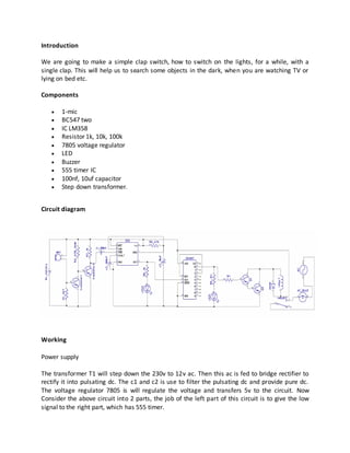
We are going to make a simple clap switch, how to switch on the lights, for a while, with a single clap. This will help us to search some objects in the dark, when you are watching TV or lying on bed etc. Components • 1-mic • BC547 two • IC LM358 • Resistor 1k, 10k, 100k • 7805 voltage regulator • LED • Buzzer • 555 timer IC • 100nf, 10uf capacitor • Step down transformer.

Recommended
More Related Content
What's hot
What's hot (17)
Similar to Clap switch mini project using 555 timer IC
Similar to Clap switch mini project using 555 timer IC (20)
More from Erole technologies Pvt. Ltd
More from Erole technologies Pvt. Ltd (9)
Recently uploaded
Recently uploaded (20)
Clap switch mini project using 555 timer IC
- 1. Introduction We are going to make a simple clap switch, how to switch on the lights, for a while, with a single clap. This will help us to search some objects in the dark, when you are watching TV or lying on bed etc. Components 1-mic BC547 two IC LM358 Resistor 1k, 10k, 100k 7805 voltage regulator LED Buzzer 555 timer IC 100nf, 10uf capacitor Step down transformer. Circuit diagram Working Power supply The transformer T1 will step down the 230v to 12v ac. Then this ac is fed to bridge rectifier to rectify it into pulsating dc. The c1 and c2 is use to filter the pulsating dc and provide pure dc. The voltage regulator 7805 is will regulate the voltage and transfers 5v to the circuit. Now Consider the above circuit into 2 parts, the job of the left part of this circuit is to give the low signal to the right part, which has 555 timer.
- 2. In the right part of the circuit in “ how to get the monostable output using 555 timer “. According to that, all we have to do is to provide a low signal to the 555s TRIGGER pin (pin 2) to switch on the light for a desired time. When we power up the circuit, the current will flow from source to the (+ve) mic and leaves at (-ve). Due to the low resistance of the mic the sufficient amount of current will flow to the base of Trassistor1. That current helps the Transistor1 to turn on.Due to this, the voltage across the collector-emitter of T1 is zero. So that no voltage across base-emitter of Transistor2 that is the reason why the T2 is in off state by default. When T2 is turned off the voltage across collector-emitter of T2 was almost equal to the source voltage. As discussed before trigger requires low signal to on the 555.When the sound was detected by the mic the resistance of the mic will become high. Due to this, there is no current flow to the base of T1 which makes the T1 to turn OFF. Due to this, the voltage across the collector-emitter of T1 was high; this makes the T2 to turn ON. Once the T2 was in ON, the voltage across collector- emitter of T2 will be low. This LOW was sensed by the trigger pin (pin 2), which makes the 555 to produce the monostable output time is set by resistance R5 and capacitor c5. What is 555 Timer??? Basically, 555 timers is an 8-pin integrated chip which has capable of producing accurate time delays or oscillation. By connecting different values of resistor and capacitor to a 555 timer we can use it for countless applications. Monostable state “For a single low trigger input, the output pulse goes to high (we can increase or decrease the ‘high state’ time) and come back to low. “In simple, it’s a one pulse mode. By default the output of this circuit will be low (‘0’). When we give a low signal to a trigger pin. The output will go to high (‘1’) for a certain time and it will come back to the low state. The time for which the output stays high can be controlled by a suitable RC application. Application Use to control light/fan using clap.
- 3. Shop online @ www.eroletech.com Call Now: +91 7007957715, +91 7081584848 Email: eroletech@gmail.com Alsodeals inElectronic Kits, Components, Modules&Mechanical Parts Lowest Cost Guaranty