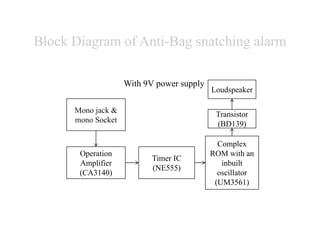
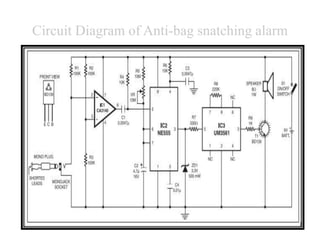
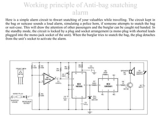
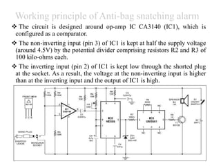
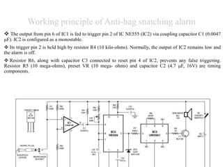
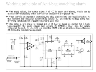
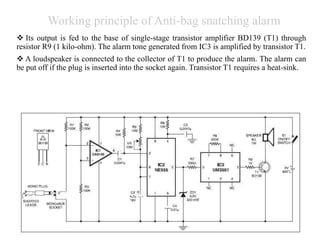
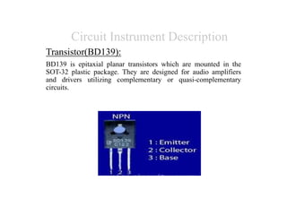
ANTI-BAG
SNATCHING ALARM
Background
Nowadays people always remains terrified of snatchers. Day
by day it is increasing in a society. Specially, the women are
not safe with their purse outside. For this reason, to remove
snatching the American inventors Richard W. Dixon
invented purse theft alarm on 1971. it was the first use of
theft alarm. It was based on the theory that a sudden pull or
jerking force exerted by the purse handle will cause the
alarm to be ACTIVATED.
Executive Summary
Here is a very simple as well as very useful project anti bag snatching
alarm, used in bag or suitcase in order to prevent from snatching. The
heart of this entire circuit anti bag snatching alarm is operational
amplifier IC CA3140 (IC1), configured as a comparator. The two inputs
(inverting and non – inverting) is given to pin no 3 and 2 of operational
amplifier respectively and output is obtained from pin no 6. output.
•Here IC2 (timer IC NE555) is used as
monostable multivibrator. The timing
component of anti bag snatching alarm is R5,
VR1, and capacitor C2 with the given value in
this circuit diagram lets the time of timer is
about 1 minute. For audio section, IC3 is used as
alarm tone generator with an inbuilt oscillator.
Finally the output is obtained from pin no 3 of
IC3 and amplified by transistor T1 in order to get
desire level and lastly fed to loudspeaker.
Objectives
 To design and construct Anti-Bag snatching alarm for
getting rid of snatching and captured the snatchers.
 To provide a thief alarm device that practically
eliminates accidental triggering thereof.
Block Diagram of Anti-Bag snatching alarm
With 9V power supply
Operation
Amplifier
(CA3140)
Timer IC
(NE555)
Complex
ROM with an
inbuilt
oscillator
(UM3561)
Mono jack &
mono Socket
Transistor
(BD139)
Loudspeaker
BASIC IDEA
• ACTIVATOR
( When monoplug detaches)
SIGNAL AMPLIFIER
(IC1 CA3140 operation amplifier,Transistor BD139)
FREQUENCY GENERATOR
(IC2 NE555 monostable,IC3 UM3561 oscillator)
SPEAKER
Circuit Diagram of Anti-bag snatching alarm
Working principle of Anti-bag snatching
alarm
Here is a simple alarm circuit to thwart snatching of your valuables while travelling. The circuit kept in
the bag or suitcase sounds a loud alarm, simulating a police horn, if someone attempts to snatch the bag
or suit-case. This will draw the attention of other passengers and the burglar can be caught red handed. In
the standby mode, the circuit is locked by a plug and socket arrangement (a mono plug with shorted leads
plugged into the mono-jack socket of the unit). When the burglar tries to snatch the bag, the plug detaches
from the unit’s socket to activate the alarm.
Working principle of Anti-bag snatching alarm
 The circuit is designed around op-amp IC CA3140 (IC1), which is
configured as a comparator.
 The non-inverting input (pin 3) of IC1 is kept at half the supply voltage
(around 4.5V) by the potential divider comprising resistors R2 and R3 of
100 kilo-ohms each.
 The inverting input (pin 2) of IC1 is kept low through the shorted plug
at the socket. As a result, the voltage at the non-inverting input is higher
than at the inverting input and the output of IC1 is high.
Working principle of Anti-bag snatching alarm
 The output from pin 6 of IC1 is fed to trigger pin 2 of IC NE555 (IC2) via coupling capacitor C1 (0.0047
μF). IC2 is configured as a monostable.
 Its trigger pin 2 is held high by resistor R4 (10 kilo-ohms). Normally, the output of IC2 remains low and
the alarm is off.
 Resistor R6, along with capacitor C3 connected to reset pin 4 of IC2, prevents any false triggering.
Resistor R5 (10 mega-ohms), preset VR (10 mega- ohms) and capacitor C2 (4.7 μF, 16V) are timing
components.
Working principle of Anti-bag snatching alarm
 With these values, the output at pin 3 of IC2 is about one minute, which can be
increased by increasing either the value of capacitor C2 or preset VR.
 When there is an attempt at snatching, the plug connected to the circuit detaches. At
that moment, the voltage at the inverting input of IC1 exceeds the voltage at the non-
inverting input and sub-sequently its output goes low.
 This sends a low pulse to trigger pin 2 of IC2 to make its output pin 3 high.
Consequently, the alarm circuit built around IC UM3561 (IC3) gets the supply
voltage at its pin 5. IC UM3561 is a complex ROM with an inbuilt oscillator. Resistor
R8 forms the oscillator component.
Working principle of Anti-bag snatching alarm
 Its output is fed to the base of single-stage transistor amplifier BD139 (T1) through
resistor R9 (1 kilo-ohm). The alarm tone generated from IC3 is amplified by transistor T1.
 A loudspeaker is connected to the collector of T1 to produce the alarm. The alarm can
be put off if the plug is inserted into the socket again. Transistor T1 requires a heat-sink.
Working principle of Anti-bag snatching alarm
 Resistor R7 (330 ohms) limits the current to IC3 and zener diode ZD1 limits the
supply voltage to IC3 to a safe level of 3.3 volts. Resistor R9 limits the cur- rent
to the base of T1.
 The circuit can be easily constructed on a vero board or general-purpose PCB.
Using a small case for housing the circuit and 9V battery. The speaker should be
small so as to make the gadget handy. Connecting a thin plastic wire to the plug
and securing it in hand or tie up somewhere else so that when the bag is pulled,
the plug detaches from the socket easily.
Circuit Instrument Description
Operational Amplifier:
The IC requires very low input current as low as 10pA to change
the output status, high or low. The IC has very fast response and
high speed of performance. The output stage of the IC uses bipolar
transistors and includes built in protection against damage from
load terminal short circuiting to either supply rails or to ground.
Circuit Instrument Description
Timer IC (NE555):
555 is a very commonly used IC for generating accurate timing pulses. It is an 8pin timer
IC and has mainly two modes of operation: monostable and astable. In monostable mode
time delay of the pulses can be precisely controlled by an external resistor and a capacitor
whereas in astable mode the frequency & duty cycle (the cycle of operation of a machine or
other device which operates intermittently rather than continuously.) are controlled by two
external resistors and a capacitor. 555 is very commonly used for generating time delay and
pulses.
Circuit Instrument Description
Variable resistor:
A potentiometer informally a pot, is a three-terminal resistor with a
sliding or rotating contact that forms an adjustable voltage divider. If
only two terminals are used, one end and the wiper, it acts as a variable
resistor or rheostat.
Circuit Instrument Description
Transistor(BD139):
BD139 is epitaxial planar transistors which are mounted in the
SOT-32 plastic package. They are designed for audio amplifiers
and drivers utilizing complementary or quasi-complementary
circuits.
Circuit Instrument Description
Complex ROM with an inbuilt oscillator (UM3561):
UM 3561 is an excellent Siren generator IC widely used in Toy applications and Surveillance systems to
generate different tones. It a ROM (Read Only Memory) IC which can be operated in 2 pen cells and it
functions normally down to 2.4 volts. Using only a few components, it is very easy to construct a siren
generator. The IC is designed to generate sirens like Police siren, Ambulance siren, Fire brigade siren and
Machine gun sound. The IC has an inbuilt oscillator and tone selection pins. Only one external resistor and a
soeaker driver transistor are sufficient to make a simple siren generator circuit.
Circuit Instrument Description
Zener Diode:
A Zener diode is a diode which allows current to flow in the forward
direction in the same manner as an ideal diode, but also permits it to flow
in the reverse direction when the voltage is above a certain value known
as the breakdown voltage. We use 3.3v Zener diode in this circuit.
Circuit Instrument Description
Speaker:
A loudspeaker (or loud-speaker or speaker) is an electroacoustic
transducer, a device which converts an electrical audio signal into a
corresponding sound.
Advantages:
Simple circuit design.
Low cost.
Bias voltage is low.
Its easy to carry anywhere.
Effectively applied in daily activities.
Disadvantages:
 Its create noise because of police siren in the public
place.
Applications
 used in motor cycle to prevenT theft.
 used in door of your Private room.
 used in laptop, if anyone open it, the alarm activates.
 used in suitcase, bag, purse etc. to prevent theft.
Conclusion
It can be used in a bag which prevents snatching and saves our
life. When the bag is snatched then plug is detached and the
alarm is activated immediately. Everyone can use this device by
exchanging a small amount of price of just Rs ₹320.

Anti bag snatching alarm

  • 1.
  • 2.
    Background Nowadays people alwaysremains terrified of snatchers. Day by day it is increasing in a society. Specially, the women are not safe with their purse outside. For this reason, to remove snatching the American inventors Richard W. Dixon invented purse theft alarm on 1971. it was the first use of theft alarm. It was based on the theory that a sudden pull or jerking force exerted by the purse handle will cause the alarm to be ACTIVATED.
  • 3.
    Executive Summary Here isa very simple as well as very useful project anti bag snatching alarm, used in bag or suitcase in order to prevent from snatching. The heart of this entire circuit anti bag snatching alarm is operational amplifier IC CA3140 (IC1), configured as a comparator. The two inputs (inverting and non – inverting) is given to pin no 3 and 2 of operational amplifier respectively and output is obtained from pin no 6. output.
  • 4.
    •Here IC2 (timerIC NE555) is used as monostable multivibrator. The timing component of anti bag snatching alarm is R5, VR1, and capacitor C2 with the given value in this circuit diagram lets the time of timer is about 1 minute. For audio section, IC3 is used as alarm tone generator with an inbuilt oscillator. Finally the output is obtained from pin no 3 of IC3 and amplified by transistor T1 in order to get desire level and lastly fed to loudspeaker.
  • 5.
    Objectives  To designand construct Anti-Bag snatching alarm for getting rid of snatching and captured the snatchers.  To provide a thief alarm device that practically eliminates accidental triggering thereof.
  • 6.
    Block Diagram ofAnti-Bag snatching alarm With 9V power supply Operation Amplifier (CA3140) Timer IC (NE555) Complex ROM with an inbuilt oscillator (UM3561) Mono jack & mono Socket Transistor (BD139) Loudspeaker
  • 7.
    BASIC IDEA • ACTIVATOR (When monoplug detaches) SIGNAL AMPLIFIER (IC1 CA3140 operation amplifier,Transistor BD139) FREQUENCY GENERATOR (IC2 NE555 monostable,IC3 UM3561 oscillator) SPEAKER
  • 8.
    Circuit Diagram ofAnti-bag snatching alarm
  • 9.
    Working principle ofAnti-bag snatching alarm Here is a simple alarm circuit to thwart snatching of your valuables while travelling. The circuit kept in the bag or suitcase sounds a loud alarm, simulating a police horn, if someone attempts to snatch the bag or suit-case. This will draw the attention of other passengers and the burglar can be caught red handed. In the standby mode, the circuit is locked by a plug and socket arrangement (a mono plug with shorted leads plugged into the mono-jack socket of the unit). When the burglar tries to snatch the bag, the plug detaches from the unit’s socket to activate the alarm.
  • 10.
    Working principle ofAnti-bag snatching alarm  The circuit is designed around op-amp IC CA3140 (IC1), which is configured as a comparator.  The non-inverting input (pin 3) of IC1 is kept at half the supply voltage (around 4.5V) by the potential divider comprising resistors R2 and R3 of 100 kilo-ohms each.  The inverting input (pin 2) of IC1 is kept low through the shorted plug at the socket. As a result, the voltage at the non-inverting input is higher than at the inverting input and the output of IC1 is high.
  • 11.
    Working principle ofAnti-bag snatching alarm  The output from pin 6 of IC1 is fed to trigger pin 2 of IC NE555 (IC2) via coupling capacitor C1 (0.0047 μF). IC2 is configured as a monostable.  Its trigger pin 2 is held high by resistor R4 (10 kilo-ohms). Normally, the output of IC2 remains low and the alarm is off.  Resistor R6, along with capacitor C3 connected to reset pin 4 of IC2, prevents any false triggering. Resistor R5 (10 mega-ohms), preset VR (10 mega- ohms) and capacitor C2 (4.7 μF, 16V) are timing components.
  • 12.
    Working principle ofAnti-bag snatching alarm  With these values, the output at pin 3 of IC2 is about one minute, which can be increased by increasing either the value of capacitor C2 or preset VR.  When there is an attempt at snatching, the plug connected to the circuit detaches. At that moment, the voltage at the inverting input of IC1 exceeds the voltage at the non- inverting input and sub-sequently its output goes low.  This sends a low pulse to trigger pin 2 of IC2 to make its output pin 3 high. Consequently, the alarm circuit built around IC UM3561 (IC3) gets the supply voltage at its pin 5. IC UM3561 is a complex ROM with an inbuilt oscillator. Resistor R8 forms the oscillator component.
  • 13.
    Working principle ofAnti-bag snatching alarm  Its output is fed to the base of single-stage transistor amplifier BD139 (T1) through resistor R9 (1 kilo-ohm). The alarm tone generated from IC3 is amplified by transistor T1.  A loudspeaker is connected to the collector of T1 to produce the alarm. The alarm can be put off if the plug is inserted into the socket again. Transistor T1 requires a heat-sink.
  • 14.
    Working principle ofAnti-bag snatching alarm  Resistor R7 (330 ohms) limits the current to IC3 and zener diode ZD1 limits the supply voltage to IC3 to a safe level of 3.3 volts. Resistor R9 limits the cur- rent to the base of T1.  The circuit can be easily constructed on a vero board or general-purpose PCB. Using a small case for housing the circuit and 9V battery. The speaker should be small so as to make the gadget handy. Connecting a thin plastic wire to the plug and securing it in hand or tie up somewhere else so that when the bag is pulled, the plug detaches from the socket easily.
  • 15.
    Circuit Instrument Description OperationalAmplifier: The IC requires very low input current as low as 10pA to change the output status, high or low. The IC has very fast response and high speed of performance. The output stage of the IC uses bipolar transistors and includes built in protection against damage from load terminal short circuiting to either supply rails or to ground.
  • 16.
    Circuit Instrument Description TimerIC (NE555): 555 is a very commonly used IC for generating accurate timing pulses. It is an 8pin timer IC and has mainly two modes of operation: monostable and astable. In monostable mode time delay of the pulses can be precisely controlled by an external resistor and a capacitor whereas in astable mode the frequency & duty cycle (the cycle of operation of a machine or other device which operates intermittently rather than continuously.) are controlled by two external resistors and a capacitor. 555 is very commonly used for generating time delay and pulses.
  • 17.
    Circuit Instrument Description Variableresistor: A potentiometer informally a pot, is a three-terminal resistor with a sliding or rotating contact that forms an adjustable voltage divider. If only two terminals are used, one end and the wiper, it acts as a variable resistor or rheostat.
  • 18.
    Circuit Instrument Description Transistor(BD139): BD139is epitaxial planar transistors which are mounted in the SOT-32 plastic package. They are designed for audio amplifiers and drivers utilizing complementary or quasi-complementary circuits.
  • 19.
    Circuit Instrument Description ComplexROM with an inbuilt oscillator (UM3561): UM 3561 is an excellent Siren generator IC widely used in Toy applications and Surveillance systems to generate different tones. It a ROM (Read Only Memory) IC which can be operated in 2 pen cells and it functions normally down to 2.4 volts. Using only a few components, it is very easy to construct a siren generator. The IC is designed to generate sirens like Police siren, Ambulance siren, Fire brigade siren and Machine gun sound. The IC has an inbuilt oscillator and tone selection pins. Only one external resistor and a soeaker driver transistor are sufficient to make a simple siren generator circuit.
  • 20.
    Circuit Instrument Description ZenerDiode: A Zener diode is a diode which allows current to flow in the forward direction in the same manner as an ideal diode, but also permits it to flow in the reverse direction when the voltage is above a certain value known as the breakdown voltage. We use 3.3v Zener diode in this circuit.
  • 21.
    Circuit Instrument Description Speaker: Aloudspeaker (or loud-speaker or speaker) is an electroacoustic transducer, a device which converts an electrical audio signal into a corresponding sound.
  • 22.
    Advantages: Simple circuit design. Lowcost. Bias voltage is low. Its easy to carry anywhere. Effectively applied in daily activities. Disadvantages:  Its create noise because of police siren in the public place.
  • 23.
    Applications  used inmotor cycle to prevenT theft.  used in door of your Private room.  used in laptop, if anyone open it, the alarm activates.  used in suitcase, bag, purse etc. to prevent theft.
  • 24.
    Conclusion It can beused in a bag which prevents snatching and saves our life. When the bag is snatched then plug is detached and the alarm is activated immediately. Everyone can use this device by exchanging a small amount of price of just Rs ₹320.