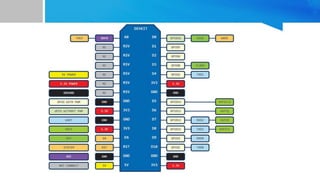
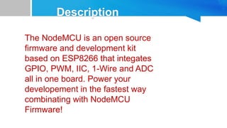
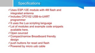
Price:
Rs. 300.00 to Rs. 417.00
CIRCUIT DIAGRAM
• This wireless Transceiver module is an easy and
suitable module if you want to setup your wireless
communication system with low cost!!
• It can achieve a good balance between wireless
transition performance and cost!
• You can easily add it with your own
MCU/ARM/PIC/AVR/STM32 system! What's more,
• this nRF24L01+ module is designed with Power
amplifier and SMA antenna
• This allowed you to use the wireless communication up
to 1000 meters! (No barrier)
 Frequence: 2.4GHz~2.5GHz
 Operating voltage: 3 ~ 3.6V Max
 Current: 115mA
 Multi-frequency: 125 frequency
 Support up to six channels of data
reception
 Frequence: 2.4GHz~2.5GHz
 Operating voltage: 3 ~ 3.6V Max
 Current: 115mA
 Multi-frequency: 125 frequency
 Support up to six channels of data
reception
Price:
Rs. 400.00 to Rs. 600.00
 SI4432 wireless module 1000 meters long distance
 ultra-compact, harmonic too easy to FCC /
CE certification
 penetrating ability SI4432 IC, stable performance
 Frequency Range: 433.92M
 Sensitivity up to-121 dBm
 Maximum output power: 20dBm
 Data transfer rate :0.123-256 kbps
 FSK, GFSK and OOK modulation mode
 1.8-3.6 V power supply
 Low consumption shutdown mode
 Digital received signal strength indicator (RSSI)
 Timing wake-up function
 The antenna automatically match and two-way switch
control
 Configurable packet structure
 Preamble signal detection
 64-byte transmit and receive data register (FIFO)
 The low-power detection
 Temperature sensors and 8-bit analog-to-digital converter
 Operating temperature range: -20 to +60 ° C
 Integrated voltage regulator
 Frequency hopping function
 Power-on reset function
 Built-in crystal adjustment
 Remote control
 Remote meter reading
 Home security alarm and remote keyless entry
 Industrial control
 Home automation telemetry
 Personal data record
 Toy control
 Sensor networks
 Tire Pressure Monitoring
 Health Monitoring
 Wireless PC peripherals
 Tag reader
 1CND power supply
 2 GPIO0 internal module, launch control foot
 3 GPI01 internal access module to accept control foot
 4 GPIO2 directly connected to the chip GIIO2 pin
 5 VCC positive supply 3.3V
 6 SDO 0-VDD V digital output provides a serial readback function of the internal control register
 7 SDI serial data input. 0-VDD V digital input, this pin for 4-wire serial data clock function
 8 SCLK serial clock input. 0-VDDV last month set of inputs. This pin provides a 4-wire serial data clock function
 9 NSEL serial interface select input pin,0-VDDV digital input. This pin to 4-wire serial data bus select / enable
function,
 this signal is also used, said the burst read / write mode.
 10 NIRQ interrupt output pin
 11 SDN Close the input pin. Input 0-VDDV digital. SDN = 0 in shutdown mode, so mode
 12 GND access power ground
 13 ANT 50 ohm coaxial antenna
Price:
Rs. 300.00 to Rs. 500.00
 Supply voltage: 3.2V~5.5V. (If the module you want to work long hours in the
emission state,
it is recommended that when the supply voltage exceeds 4.5V threaded a
1N4007 diode
to prevent module built-in LDO heated)
 Default address range (open field test): About 600m (maximum communication
distance
adjustable reach 1000m, the baud rate is 5000bps)
 Default idle current: 16MA (In different working modes operating current is
different)
 Module dimensions: 27.8 x 14.4 x 4mm
 Operating frequency range: 433.4-473.0MHz, up to 100 channels of
communication
 The maximum transmit power: 100mW (settable)
 Module support software upgrade
 Default factory settings: Mode FU3, baud rate is 9600bps, communication
channels CH001 (433.4M)
Example:
Set module to channel 21, please send module command "AT + C021", the module returns "OK + C021".
After exiting the command mode, the module in the first 21 channels, operating frequency is 441.4 MHz.
Note: Because the wireless receiver module sensitivity HC-12 is relatively high, the baud rate is greater
than when air 58000 bps, 5 must be shifted to the adjacent channel use. When the air baud rate is not
greater than 58000 bps, if the short distance (10 meters) communication, but also need to stagger five
adjacent channel use.
4. AT + FUx
Change the module serial pass-through mode, there FU1, FU2 and FU3 three modes. Module default
mode is FU3, two serial pass-through mode module must be set to the same communication.
See detailed above, "wireless serial pass-through" part.
Example: Send module commands "AT + FU1", the module returns "AT + OK".
5. AT + Px
1. AT
Test instructions
Example: Send module commands "AT", the module returns "OK".
2. AT + Bxxxx
Change the serial port baud rate command. You can set the baud rate is
1200bps, 2400bps, 4800bps, 9600bps, 19200bps, 38400bps, 57600bps and
115200bps. The factory default is 9600bps.
Example: Set the module serial port baud rate is 19200bps, please send
module command "AT + B19200", the module returns
"OK + B19200".
3. AT + Cxxx
Change the wireless communication channel, selectable from 001 to 127
(more than 100 radio channels
after the communication distance not guaranteed). The default value is 001
radio channels, operating
frequency is 433.4MHz. Step channel is 400KHz, the operating frequency of
the channel 100
is 473.0 MHz.
Price:
Rs. 300.00 to Rs. 417.00
The NodeMCU is an open source
firmware and development kit
based on ESP8266 that integates
GPIO, PWM, IIC, 1-Wire and ADC
all in one board. Power your
developement in the fastest way
combinating with NodeMCU
Firmware!
 NodeMCU is the most popular development board for the hugely popular
WiFi IoT chip from Espressif, the ESP8266.
 It uses the Lua scripting language to make it easy to run user programs
on the ESP8266 without any recompilation.
 The board consists of an
1. ESP-12E module,
2. CP2102 (for usb to uart),
3. and USB connector for power.
 All the pins of the ESP-12E are brought out on compact and narrow
board design to make it breadboard friendly.
 You can use the nodemcu firmware, or the Arduino development
environment or build your own firmware using Espressif's SDK for the
ESP8266.
• Arduino-like hardware IO
• NodeJS style network API
• Lowest cost WIFI development tool
• Reprogramming possibility
• Multiple uses
• Use directly in your application
• One ADC input and 8 digital IOs
• 3.3V operation
• Compact size: 25.4mm x 50.8mm (2" x 1")
• Provision for external battery along with on/off switch
:
Uses ESP-12E module with 4M flash and
integrated antenna
Includes CP2102 USB-to-UART
programmer
It uses the Lua scripting language
Lot of modules and example code snippets
available here.
Open sourced
Compact/narrow Breadboard friendly
design
push buttons for reset and flash
Powered by micro usb cable

Long range wireless modules

  • 2.
  • 4.
  • 5.
    • This wirelessTransceiver module is an easy and suitable module if you want to setup your wireless communication system with low cost!! • It can achieve a good balance between wireless transition performance and cost! • You can easily add it with your own MCU/ARM/PIC/AVR/STM32 system! What's more, • this nRF24L01+ module is designed with Power amplifier and SMA antenna • This allowed you to use the wireless communication up to 1000 meters! (No barrier)
  • 6.
     Frequence: 2.4GHz~2.5GHz Operating voltage: 3 ~ 3.6V Max  Current: 115mA  Multi-frequency: 125 frequency  Support up to six channels of data reception  Frequence: 2.4GHz~2.5GHz  Operating voltage: 3 ~ 3.6V Max  Current: 115mA  Multi-frequency: 125 frequency  Support up to six channels of data reception
  • 7.
  • 9.
     SI4432 wirelessmodule 1000 meters long distance  ultra-compact, harmonic too easy to FCC / CE certification  penetrating ability SI4432 IC, stable performance  Frequency Range: 433.92M  Sensitivity up to-121 dBm  Maximum output power: 20dBm  Data transfer rate :0.123-256 kbps  FSK, GFSK and OOK modulation mode  1.8-3.6 V power supply  Low consumption shutdown mode  Digital received signal strength indicator (RSSI)  Timing wake-up function  The antenna automatically match and two-way switch control  Configurable packet structure  Preamble signal detection  64-byte transmit and receive data register (FIFO)  The low-power detection  Temperature sensors and 8-bit analog-to-digital converter  Operating temperature range: -20 to +60 ° C  Integrated voltage regulator  Frequency hopping function  Power-on reset function  Built-in crystal adjustment
  • 10.
     Remote control Remote meter reading  Home security alarm and remote keyless entry  Industrial control  Home automation telemetry  Personal data record  Toy control  Sensor networks  Tire Pressure Monitoring  Health Monitoring  Wireless PC peripherals  Tag reader
  • 11.
     1CND powersupply  2 GPIO0 internal module, launch control foot  3 GPI01 internal access module to accept control foot  4 GPIO2 directly connected to the chip GIIO2 pin  5 VCC positive supply 3.3V  6 SDO 0-VDD V digital output provides a serial readback function of the internal control register  7 SDI serial data input. 0-VDD V digital input, this pin for 4-wire serial data clock function  8 SCLK serial clock input. 0-VDDV last month set of inputs. This pin provides a 4-wire serial data clock function  9 NSEL serial interface select input pin,0-VDDV digital input. This pin to 4-wire serial data bus select / enable function,  this signal is also used, said the burst read / write mode.  10 NIRQ interrupt output pin  11 SDN Close the input pin. Input 0-VDDV digital. SDN = 0 in shutdown mode, so mode  12 GND access power ground  13 ANT 50 ohm coaxial antenna
  • 12.
  • 14.
     Supply voltage:3.2V~5.5V. (If the module you want to work long hours in the emission state, it is recommended that when the supply voltage exceeds 4.5V threaded a 1N4007 diode to prevent module built-in LDO heated)  Default address range (open field test): About 600m (maximum communication distance adjustable reach 1000m, the baud rate is 5000bps)  Default idle current: 16MA (In different working modes operating current is different)  Module dimensions: 27.8 x 14.4 x 4mm  Operating frequency range: 433.4-473.0MHz, up to 100 channels of communication  The maximum transmit power: 100mW (settable)  Module support software upgrade  Default factory settings: Mode FU3, baud rate is 9600bps, communication channels CH001 (433.4M)
  • 15.
    Example: Set module tochannel 21, please send module command "AT + C021", the module returns "OK + C021". After exiting the command mode, the module in the first 21 channels, operating frequency is 441.4 MHz. Note: Because the wireless receiver module sensitivity HC-12 is relatively high, the baud rate is greater than when air 58000 bps, 5 must be shifted to the adjacent channel use. When the air baud rate is not greater than 58000 bps, if the short distance (10 meters) communication, but also need to stagger five adjacent channel use. 4. AT + FUx Change the module serial pass-through mode, there FU1, FU2 and FU3 three modes. Module default mode is FU3, two serial pass-through mode module must be set to the same communication. See detailed above, "wireless serial pass-through" part. Example: Send module commands "AT + FU1", the module returns "AT + OK". 5. AT + Px
  • 16.
    1. AT Test instructions Example:Send module commands "AT", the module returns "OK". 2. AT + Bxxxx Change the serial port baud rate command. You can set the baud rate is 1200bps, 2400bps, 4800bps, 9600bps, 19200bps, 38400bps, 57600bps and 115200bps. The factory default is 9600bps. Example: Set the module serial port baud rate is 19200bps, please send module command "AT + B19200", the module returns "OK + B19200". 3. AT + Cxxx Change the wireless communication channel, selectable from 001 to 127 (more than 100 radio channels after the communication distance not guaranteed). The default value is 001 radio channels, operating frequency is 433.4MHz. Step channel is 400KHz, the operating frequency of the channel 100 is 473.0 MHz.
  • 17.
  • 20.
    The NodeMCU isan open source firmware and development kit based on ESP8266 that integates GPIO, PWM, IIC, 1-Wire and ADC all in one board. Power your developement in the fastest way combinating with NodeMCU Firmware!
  • 21.
     NodeMCU isthe most popular development board for the hugely popular WiFi IoT chip from Espressif, the ESP8266.  It uses the Lua scripting language to make it easy to run user programs on the ESP8266 without any recompilation.  The board consists of an 1. ESP-12E module, 2. CP2102 (for usb to uart), 3. and USB connector for power.  All the pins of the ESP-12E are brought out on compact and narrow board design to make it breadboard friendly.  You can use the nodemcu firmware, or the Arduino development environment or build your own firmware using Espressif's SDK for the ESP8266.
  • 22.
    • Arduino-like hardwareIO • NodeJS style network API • Lowest cost WIFI development tool • Reprogramming possibility • Multiple uses • Use directly in your application • One ADC input and 8 digital IOs • 3.3V operation • Compact size: 25.4mm x 50.8mm (2" x 1") • Provision for external battery along with on/off switch
  • 23.
    : Uses ESP-12E modulewith 4M flash and integrated antenna Includes CP2102 USB-to-UART programmer It uses the Lua scripting language Lot of modules and example code snippets available here. Open sourced Compact/narrow Breadboard friendly design push buttons for reset and flash Powered by micro usb cable