The document describes a CPU design that consists of a control block and ALU block, where the control block handles the state machine for memory interfacing and controlling the ALU functions, and the ALU block contains an 8x16 register file and performs arithmetic and logical operations on register operands as specified by instruction fields. The CPU can perform operations like addition, subtraction, logical AND, load from memory, store to memory, and jumping based on instruction codes.
This document discusses the thermal characteristics of LEDs. It shows that as the junction temperature of an LED increases, its light output decreases, forward voltage drops, color shifts to lower wavelengths, and maximum ratings can be exceeded. The document emphasizes that LED specifications are based on standardized testing conditions, while actual applications may have different thermal environments, so temperature effects must be considered in design.
The document describes a charge equalization unit (CEU) for a NiCd battery used in a small earth observation satellite. The CEU uses a multi-winding transformer and isolated flyback DC-DC converters to dynamically equalize the charge between battery cells. This helps protect the battery from damage and increases its lifetime by preventing deep discharging or reverse polarity of weak cells. The CEU design and simulation results are shown for an 11-cell battery configuration.
This document provides information about the course "Basic Electronics" including the course code, semester, subject title, teaching and examination scheme, rationale, objectives, learning structure, procedures, concepts, contents, and practical skills. The course is offered in the third semester and covers topics such as semiconductor diodes, rectifiers, filters, transistors, biasing circuits, and small signal amplifiers. The objectives are for students to understand components like diodes and transistors, draw basic circuits, know voltage amplifiers, test diodes and transistors, and read datasheets. The document outlines the course contents across 6 chapters and 12 practical experiments that develop intellectual and motor skills.
ElectroMagnetic Induction from Advanced NRG SolutionsADHenderson
Advanced NRG Solutions and LVD work together to provide energy saving lighting solutions. Advanced NRG Solutions is a consulting firm that represents manufacturers like LVD. LVD is a lighting company that produces long-lasting induction lamps with higher efficiency than LEDs. Case studies show induction lamps from LVD provide better lighting than high pressure sodium lamps while reducing energy costs by over 50% for applications like street lights and industrial lighting.
Presented by Theodore Bohn, Argonne National Laboratory, on August 24, 2011, at the "Charge Up Wisconsin!" plug-in electric vehicle implementation meeting hosted by Wisconsin Clean Cities.
This document provides specifications for two duct connection high static pressure indoor units (FD05KAY1 and FD06KAY1) that can be used with specific outdoor units (RU05NY1 and RU06NY1). It includes details on cooling capacities, power input, dimensions, coil specifications, fan specifications, compressor type, controls and safety devices for both the indoor and outdoor units. It also provides information on piping connections, refrigerant type, piping lengths, and refrigerant charge amounts.
This is Solar Array Simulator to test the solar inverters for Maximum Power Point Tracking (MPPT) with dynamic simulation of Voc, Isc (I-V curves), Irradiation, Temperature coefficients, diff daly light conditions including cloudy, rainy dark conditions.
About 7 installations already in India in research & educational institutions
The document describes the Eutech 2700 series of bench meters for measuring pH, ORP, ION, conductivity, TDS, salinity, resistivity, dissolved oxygen, and temperature. The meters feature a backlit display, temperature display, memory storage, calibration reports, detachable electrode holders, and more. They are compact, durable, and have large displays. The document provides details on specific models for pH, ION, and conductivity measurement and their applications in educational and laboratory settings.
This document discusses off-grid solar power as the lowest hanging fruit for implementing solar power in the MENA region. It summarizes that there are several gigawatts of existing micro-grids that run on diesel fuel. While solar is becoming more cost competitive with diesel, high upfront costs, load management challenges, and the temporary nature of off-grid needs have prevented solar from taking over more of the off-grid market. However, solar-hybrid systems are now competitive in many areas and can overcome challenges through innovations like containerized solar generator units and turbogenerator systems.
The battery reuse system (BRS) allows for the regeneration of old batteries by (1) removing lead sulfate crystals using high frequency pulses and (2) recharging batteries to the same level as new batteries. This reduces costs and environmental impacts while ensuring reliable battery performance. The document provides details on battery degradation and regeneration processes, and examples of where BRS could be implemented. Contact information is given for three models of the battery reuse system with varying voltages and capacities.
Energy storage devices (battery, capacitator): Large storage, low cost, Long life, high density, small storage, high cost, high power, high rate charge, long life
The Analysis of Dead Time on Switching Loss in High and Low Side MOSFETs of Z...IDES Editor
This work is about the analysis of dead time
variation on switching losses in a Zero Voltage Switching
(ZVS) synchronous buck converter (SBC) circuit. In high
frequency converter circuits, switching losses are
commonly linked with high and low side switches of SBC
circuit. They are activated externally by the gate driver
circuit. The duty ratio, dead time and resonant inductor
are the parameters that affect the efficiency of the circuit.
These variables can be adjusted for the optimization
purposes. The study primarily focuses on varying the
settings of input pulses of the MOSFETs in the resonant
gate driver circuit which consequently affects the
performance of the ZVS synchronous buck converter
circuit. Using the predetermined inductor of 9 nH, the
frequency is maintained at 1 MHz for each cycle
transition. The switching loss graph is obtained and
switching losses for both S1 and S2 are calculated and
compared to the findings from previous work. It has
shown a decrease in losses by 13.8 % in S1. A dead time of
15 ns has been determined to be optimized value in the
SBC design.
The document summarizes a study on the performance of energy storage systems for parallel hybrid electric vehicles. It discusses different battery types used - lead acid, nickel-metal hydride, and lithium-ion batteries. It also outlines the components of a typical parallel hybrid vehicle powertrain including the internal combustion engine, motors, and batteries. Simulation results are presented showing the state of charge variation of different battery types when tested with on-road vehicle data.
FUZZY LOGIC PROGRAMME-Fuzzy logic based differential relay for power transfor...ASHOKKUMAR RAMAR
This document discusses a fuzzy logic-based differential relay for protecting power transformers. A traditional differential relay can be falsely triggered by factors like magnetizing inrush currents and transformer overexcitation. The proposed system monitors the current difference between the primary and secondary coils using a microcontroller. It also checks for other causes of false tripping using fuzzy logic before operating the relay, thus providing more intelligent protection for power transformers.
This document provides specifications for two duct connection high static pressure indoor units (FD13KAY1 and FD15KAY1) that can be used with corresponding outdoor units (RU13NY1 and RU15NY1). Key specifications include cooling capacities, power inputs, fan details, coil configurations, dimensions, refrigerant piping details, and controls. Safety devices for both the indoor and outdoor units are also outlined.
The document summarizes a SPICE model of a 3-phase AC motor that can accurately reproduce: (1) frequency characteristics (impedance characteristics), (2) reverse electromotive force characteristics, and (3) physical characteristics. The model is characterized by parameters including phase inductance, resistance, back-EMF constant, torque constant, and load current. Simulation results show characteristics such as phase current, back-EMF, speed, torque, power output, and efficiency under varying load conditions.
Research Inventy : International Journal of Engineering and Scienceresearchinventy
Research Inventy : International Journal of Engineering and Science is published by the group of young academic and industrial researchers with 12 Issues per year. It is an online as well as print version open access journal that provides rapid publication (monthly) of articles in all areas of the subject such as: civil, mechanical, chemical, electronic and computer engineering as well as production and information technology. The Journal welcomes the submission of manuscripts that meet the general criteria of significance and scientific excellence. Papers will be published by rapid process within 20 days after acceptance and peer review process takes only 7 days. All articles published in Research Inventy will be peer-reviewed.
Solar tracker with stepper motor control using microcontrollerEcwayt
This project uses a microcontroller to control the position of a solar panel based on sunlight levels detected by two LDR sensors. The LDR sensors measure the light falling on different points of the solar panel and convert it to analog voltages, which an ADC converts to digital signals for the microcontroller. The microcontroller compares the two signals and, if they are unequal, drives a stepper motor to adjust the panel position until the sunlight is at normal incidence across both sensors.
This document presents a practical implementation of direct torque control (DTC) for an induction motor drive using a digital signal processor (DSP). It describes the modeling and control system configuration for DTC, including the selection of state variables for flux and torque control. A sliding mode controller is designed for direct flux and torque control. Simulation and experimental results validate the DTC method and show reduced torque pulsations and constant switching frequency, demonstrating high performance of the control system.
This document discusses sensorless vector control of induction motors. It presents the dynamic modeling of induction motors using a reference frame transformation. It then describes the principles of vector control using an inverse transformation to control stator currents corresponding to the rotor flux and torque. A model reference adaptive system is proposed for sensorless speed estimation, where the speed estimate is adapted by comparing outputs of an adjustable model and reference model. Simulation results show the sensorless control approach can accurately estimate speed with good tracking performance.
This document discusses sensorless vector control of induction motors. It presents the dynamic modeling of induction motors using a reference frame transformation. It then describes the principles of vector control using an inverse transformation to control stator currents. A model reference adaptive system is proposed for sensorless speed estimation, where an adaptive model estimates the rotor speed by comparing its output to a reference model. Simulation results show the sensorless control approach can accurately estimate speed with good tracking performance.
This circuit provides an audio-visual warning of potential brake failure in vehicles. It constantly monitors the brake switch and uses an op-amp voltage comparator and monostable timer to detect changes in the brake switch voltage. When the brake is applied normally, a green LED blinks and buzzer sounds briefly. If brake fluid pressure drops, the red LED will remain lit and buzzer will not sound, alerting the driver to potential brake failure. The circuit can operate from the vehicle's battery and regulated power supply to avoid unwanted triggering.
This circuit provides an anti-theft alarm for bikes. It uses an infrared transmitter and receiver to detect when the front mudguard is moved into alignment with the bike's body, which could indicate an attempted theft. When the receiver detects infrared signals from the transmitter, a relay is activated that sounds the bike's horn. The circuit can be powered using the bike's battery and housed within the tool box. It allows the owner to be alerted if anyone tries to steal the bike when it is locked.
IRJET- Analysis the Speed Manage of BLDC Motor Drive using SensorsIRJET Journal
This document analyzes the speed control of a brushless DC motor (BLDC) using sensors. It begins with an introduction to BLDC motors and their advantages over brushed DC motors. It then presents the mathematical modeling of a BLDC motor, including voltage and flux linkage equations. It describes using Hall-effect sensors to sense the rotor position and control the motor. The document discusses using a PI controller for speed control and the challenges in selecting the PI gains. It concludes by presenting the methodology for mathematically modeling the motor, including the electrical and mechanical system dynamics equations.
This document discusses brushed DC motors and provides details about their key components and operating principles. It describes how a brushed DC motor works using a stator to generate a magnetic field, a rotor that spins when its windings are energized, and brushes and a commutator that mechanically switch the winding currents. It also outlines the main types of brushed DC motors, including permanent magnet, shunt-wound, series-wound, and compound-wound motors.
This document summarizes a presentation on a "Put Coin Draw Power" circuit. The circuit uses a coin detection sensor and microcontroller to detect coins inserted, count the value, and provide power to a load until the coin value is depleted. When the load switch is closed, the coin count on a 7-segment display decrements until it reaches zero, at which point the relay disconnects the load. The circuit has applications in places like hotels, game consoles, and cafes to provide prepaid power. It allows power to be drawn by inserting coins or tokens into the device.
IOSR Journal of Electronics and Communication Engineering(IOSR-JECE) is an open access international journal that provides rapid publication (within a month) of articles in all areas of electronics and communication engineering and its applications. The journal welcomes publications of high quality papers on theoretical developments and practical applications in electronics and communication engineering. Original research papers, state-of-the-art reviews, and high quality technical notes are invited for publications.
Synopsis of solar tracker and charging monitorTarun Arora
This document provides an overview and objectives of a minor project on developing a solar tracker and charging monitor system. The solar tracker uses light dependent resistors and a motor driver IC to adjust a solar panel to maintain optimal sunlight exposure throughout the day. The charging monitor uses an LED voltmeter IC to indicate the charge level of a solar power battery. The project will involve designing and implementing the circuitry on a PCB board, including ICs, resistors, capacitors, and other components to achieve the solar tracking and battery monitoring functions.
This seminar report summarizes an automatic street light system that uses an LDR (light dependent resistor) and transistor circuit to automatically turn street lights on at nightfall and off at dawn, saving energy. The main components are an LDR, transistor, resistor, LED, battery, and PCB board. The LDR detects low light levels and allows current to flow through the transistor, powering the LED light. Potential advantages include energy savings, low cost, safety and security from automated operation. Disadvantages include limited power and the light turning on in shadows. It has applications for street and domestic lighting and could save 77-81% of power consumption for street lighting.
This document describes an optimization project for an electromechanical fin control system. It includes:
1) An introduction describing the electromechanical actuator system, which uses a brushless DC motor and ballscrew actuator to control fins on a missile.
2) A system design analysis section that provides an overview of the basic operation, sizes the actuator components based on required torque and force, and analyzes constraints such as rotational acceleration.
3) A component analysis section that models the rotary to linear motion conversion for speed, force, and acceleration, calculates reflected inertias, and derives equivalent free body and rotor equations.
Automatic street light circuit using ldrSmartxProKits
This document describes an automatic street light circuit that uses an LDR (light dependent resistor) and comparator IC LM393. The LDR detects light levels and the LM393 comparator determines whether the street light should be on or off. When light falls on the LDR, it conducts and the street light stays off. When no light falls on the LDR, it does not conduct and the street light glows continuously until light is detected again. The circuit operates on a 5V DC supply and uses readily available, low-cost components like the LDR to detect light changes and automatically control the street light.
Piggott turbine design_code_dakar_presentationHanan E. Levy
The document describes a Blade Element Momentum (BEM) model and battery charging generator model developed in Matlab to estimate electricity production and blade/tower loads for Hugh Piggott wind turbine designs. The model consists of a BEM code that uses turbine geometry and airfoil data to predict shaft power and blade loads, and a generator model that balances blade power with generator output. Test results show the model accurately estimates performance for one turbine design but less accurately for another, identifying areas for improvement. The open-source code and a future web interface are intended to help turbine designers evaluate and optimize their designs.
This circuit comprises an infrared (IR) transmitter unit and receiver unit that are mounted on opposite gate pillars. When the IR beam between the units is interrupted, a melody is triggered to sound for 30 seconds from the receiver unit to alert someone that someone is at the gate. The transmitter unit uses a 38kHz IR LED and timer to transmit the IR beam. The receiver unit uses an IR sensor and timer connected to a melody generator IC to detect the beam interruption and play the melody. The units are powered separately but connected to allow the receiver to trigger when the beam is blocked.
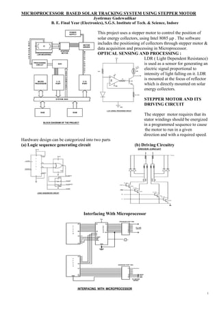
1. MICROPROCESSOR BASED SOLAR TRACKING SYSTEM USING STEPPER MOTOR
Jyotirmay Gadewadikar
B. E. Final Year (Electronics), S.G.S. Institute of Tech. & Science, Indore
This project uses a stepper motor to control the position of
solar energy collectors, using Intel 8085 mp . The software
includes the positioning of collectors through stepper motor &
data acquisition and processing in Microprocessor.
OPTICAL SENSING AND PROCESSING :
LDR ( Light Dependent Resistance)
+ Vcc
is used as a sensor for generating an
10 K
electric signal proportional to LDR
intensity of light falling on it. LDR
LM
324
is mounted at the focus of reflector
IK
SL 100
which is directly mounted on solar
GND
energy collectors.
R1 = 18
STEPPER MOTOR AND ITS
GND
DRIVING CIRCUIT
L.D.R. SIGNAL PROCESSING CIRCUIT
The stepper motor requires that its
stator windings should be energized
in a programmed sequence to cause
the motor to run in a given
direction and with a required speed.
Hardware design can be categorized into two parts
(a) Logic sequence generating circuit (b) Driving Circuitry
+5V DRIVER CIRCUIT
16 11
LOAD +5V
7
14
CLOCK 4
14
Q 1
A
1 3
3
9 Q 2
2 B
DOWN/UP 1
5
7486
7
ENABLE
4
8 TO GREEN
+5V
14
1 2 TO BLUE
3 4 TO ORANGE
7404
TO RED
LOGIC SEQUENCER CIRCUIT
Interfacing With Microprocessor
Vcc
EXPANDER PORT ONE
B7 B7
A
D TO LDR.
C CIRCUIT
8
B0 D0 0
9
A
B
C0 C
START
ALE
OE
EOC
CLK
C7
GND.
A7
A0
EXPANDER PORT TWO
C7
C1 MODE
GND. CLK.
GND.
TO MOTOR
DRIVER
1
2. THE TRACKING SOFTWARE
MAIN PROGRAM
START
LOAD M WITH 9200 LOCATION FOR
STORING O/P OF ADC. LOAD 9240 WITH 004
INITIALIZE 8255 A AND 8255 B
SELECT ANALOG INPUT CHANNEL ZERO
JUMP TO SUBROUTINE
MAKE OE LINE OF ADC LOW TO
ENABLE OUTPUT LINES
READ DIGITAL O/P AT PORT B OF
8255 B AND STORE IT INTO ACC.
TRANSFER CONTENT OF ACC. INTO
REG. D (NEW VALUE)
LOAD CONTENT OF M INTO ACC.
ACC. CONTAINS PREVIOUS VALUE
YES
LOAD REG H WITH PRESET NO
MIN. DIFFERENCE BETWEEN INCREASE M LOCATION BY ONE
SUCCESSIVE VALUES OF ADC.
SET THE CARRY TO ONE MOVE CONTENTS OF C INTO ACC.
YES YES
END
NO NO
LOAD ACC. WITH THE CONTENT MOVE CONTENT OF REG D
OF LOCATION M INTO ACC.
MOVE CONTENT OF ACC. MOVE CONTENT OF LOCATION M
TO D REG FROM ACC.
GO TO REVERSE MOTOR M : MEMORY LOCATION DENOTED BY
ROTATE REG. PAIR BC
SUBROUTINE FORWARD MOTOR ROTATE REVERSE MOTOR ROTATE
START START START
LOAD THE REG. H WITH OO4
DISABLE THE OUT PUT LOAD THE REG. H WITH 00H MAKE P1C1 LINE OF 8255 A
ENABLE OE OF ADC HIGH FOR COUNT DOWN MODE
MAKE P1C1 LINE OF 8255A MAKE P1C0 LINE OF 8225 A
LOW FOR COUNT UP MODE HIGH
CALL FORWARD MOTOR
ROTATE DELAY OF 0.125 SECONDS
DELAY OF 0.125 SECONDS
MAKE P1C0 LINE OF 8255 A
LOW
MAKE ALE AND START
LINES OF ADC HIGH MAKE P1C0 LINE OF 8255A LOW
PICO
DELAY OF 0.125 SECONDS
INCREMENT REG. H BY ONE
DELAY OF 0.125 SECONDS
MAKE START LINE LOW
LOAD A WITH 04H
INCREMENT REG. H BY ONE
YES NO
READ THE LINE P2C6 (EOC) DELAY OF 5 MINUTES
LINE OF ADC LOAD A WITH 04 H
READ THE ADC
READ THE DIGITAL O/P OF PORT B
OF 8255 B AND STORE IN A
YES
NO
TRANSFER THE CONTENTS OF A TO
MEM. LOCATION POINTED BY BC
NO
RETURN GO TO SUBROUTINE
YES
JUMP TO THE INSTURCTION NEXT
TO THE SUBROUTINE
CALL INSTRUCTION IN MAIN PROG.
2
3. MICROPROCESSOR BASED FIBRE OPTIC PRESSURE SENSOR
Jyotirmay Gadewadikar, Department of Electronics, Shri Vaishnav Institute of Technology & Science, Indore.
The system works on the principle of micro bending of optical fibres. Low cost, constructional simplicity, versatility
and microcomputer compatibility are some of the important features of the proposed device. The design of the
instrument involves a fibre optic sensor, hardware
and software parts.
Principal of Operation:
Loss of optical signal inside the fibre when pressure
is applied on the surface of a monomode optical fibre
is known as microbending losses.
Microbending loss for monomode fibres is related by
expression. µ ~ wo2+4p
p = 0,1,2…..n, n being a positive integer.
wo = Spot Size, µ = Attenuation coefficient.
Hardware design details:
Sensor : The sensor used for pressure measurement is based on microbending principle. The sensor has 2 ft. long
fiber of 50 micrometer core diameter. The Fibre is placed between two corrugated surfaces, out of which the upper
one is movable and the lower is fixed. Optical power is taken from a 6.0 V drywell torch bulb and is given to the core
of the fibre. On application of continuous physical pressure varying from .02 Kg/cm2 to 20 Kg/cm2 on the upper
surface, the fibre undergoes a proportional microbending resulting into losses and attenuation of the optical signal. A
pin photodiode(SI 100S) acts as photo detector at the receiving end of the fibre.
Signal Conditioner : Signal from photo detector is amplified through a DC Amplifier using OPAMP 741. The
analog amplified output needs to be converted to Digital Signal before it is applied to a Microprocessor which is done
through ADC 0809.
Microprocessor Interfacing Circuit: ADC is interfaced with an 8 bit Intel 8085 mP via a programmable peripheral
interface( Intel IC 8255). Clock for ADC is taken from mP after manipulation using a monolithic decade counter (
IC 7490).
Pressure Indication Circuit : ICMAN74A, a common Cathode display Chip is used for automatic display. The
circuit includes a LED decoder/driver IC 74LS48P to interface the 7 Segment display with the I/O IC 8255.
1M
1M
Software: Software design proceeds
21 IC 4
14
.
. INTEL
with the following steps
6 .
20 .
.
.
27
8085 UP 1. Control word is defined as 98H
19
216
IC 2
18
DIGITAL
(Port A, B, Cupper, Clower defined as the
O/E
17 DATA +5V D.C.
i/p port in mode 0, o/p port in mode
15
+ 5V D.C. VCC + 14 16 0,i/p port, o/p port resp.)
PB 0 7
1
8
PB 1 1
2. Control word is read from the input
5 WR 36
PB 2 2 IC 5 bus lines if MODE is high and WRITE
RESET 35
2 EDC PORT PB 3 6 is low.
7
3
6 11 10 6 PC3
CUPPER 8
13 12 11 10 9 14 15
3. After the control word has been
7 10 22
23 PC2
written into the control register, the
PORT
24
PC1
CLOWER 10 8 6 5 4 2 15 display data is written into memory
IC 1
IC 2
:
:
7490 MONOLITHIC COUNTER
ADC 0809
25
PC0 3
IC 6
with each successive negative going
IC 3 : OPAMP A741 9 WRITE pulse.
IC 4
IC 5
:
:
INTEL 8255 PPI
74LS48P DECODER / DRIVER
26
6
4. After all 8 digit memory locations
IC 6 : MAN 74A 7-SEG. DISPLAY 5 have been written addnl transitions of
WRITE are ignored. Pressure data
converted into binary codes and
subsequently into Hex-decimal
numbers and are stored into a look up table.
5. The data received from the online sensor is compared with prestored look up table.
6. Display subroutine is called.
Pressure V/S AMP. OUTPUT RESULTS & CONCLUSIONS:
6
5
The developed instrument was subjected to different magnitude of applied
pressure, it is observed that output of amplifier decreases almost linearly in
Amplifier o/p (Volts)
4
3
accordance with applied pressure, the system can be used for measuring static as
2
well as dynamic loads.
1
0
-5 0 5 10 15 20 25
Ap p lied P r es s u r e ( K g/cm 2 ) 3
4. A. I. - A REALITY
JYOTIRMAY GADEWADIKAR
B.E. IV Year Electronics
S. G. S. Institute of Technology & Science, Indore
ABSTRACT
The Computers have invaded into every walk of life. Almost in every other situation computers are being used as an
indispensable tool. The problem / processes which are complex in nature, involve number of inter-dependent variables & non-
linearities which can be solved to some extent with the help of Micro-Processors based systems/controllers. However, they are
insufficient to the extent that they fail to generate any control signal in situations which are not defined or unknown under such
circumstances, A.I. seems to resolve the problems in a much effective way. Today A.I. has been used in disciplines like
Military, Space, Medicine and Process Industry where conventional methods do not give sufficient precision & are therefore
not suitable.
This Paper is concerned with the application of Artificial Intelligence in such fields where A.I. is realized in a much effective
way.
COLD ROLLING MILL AUTOMATION
L. P. Halway (D ept. Manager), Jyotirmay Gadewadik ar(Sr. Officer)
C R M Complex, Tata Steel
ABSTRACT
India n Steel industry is employing new information technology solutions as a part of facility
re vamp ing programme to meet the challenges of the twenty-first century. The information
technology reaches obsolescence much before the manufacturing technology it supports. Hence it
is extremely important to employ IT architecture which would protect investment, allow-
incremental development and scalability, and ensure lower cost of ownership. This presentation
makes an attempt to primarily address issues related to computerization and automation and
explain an IT architecture classifying into Four Levels of Automation that can sustain the IT
requirement for a long period.
L evel 4 Sales & Distribution, manufacturing Planning, Financials, Plant maintenance,
costing Transportation
L evel 3 Production Planning & Control, Quality Control, Energy
management, Conditioning Monitoring, Process MIS
L evel 2 Material Tracking, Process Optimization, SCADA.
L evel 1 Direct control Through PLC, RTU etc.
T ata Steel is in the process of implementation of a complex IT and automatic solution for its new
CRM at Jamshedpur. The new plant is integrated with its hot strip mill. So is its new information
system, called CRMIS. There are many design trade-offs to
( i) Use the existing IT set-up and
(ii) Implement best-of-breed new te chnology solutions for the new
plant.
T his presentation addresses the information architecture in the context of a steel plant,
particularly, CRM. Implementation of the manufacturing applications and integration of th e plant
applications along with the Supply chain and Customer relationship management solutions are th e
biggest challenges to the Information System departments of all steel plants at present.
4
5. CPU Design.
Abstract: Control, ALU and External Memory Block description, performance verification using VHDL and RTL
synthesis tools. Control block handles the state machine for the memory interface and ALU functions.
A CPU (cpu.vhd) consists of 2 sub-blocks:
1. CONTROL (control.vhd)
2. ARITHMETIC (alu.vhd)
MEMORY An external memory model is
256 x 16 supplied in “memory.vhd”
CPU
CONTROL ALU
The CPU performs the following operations: Idle, Add, Subtract, AND, NOT, Load memory to Register,
Store register to memory, and Jump. (See next page.)
The ALU contains an 8 word by 16 bit register file and handles the arithmetic and logical operations. The
selection of which register words the operation is performed on comes from the instruction source1, source2,
and destination fields. For example if an addition operation with source1=0 and source2=5 and the
destination=1, then the register words 0 and 5 are added together and the result placed in register 1.
The control block handles the state machine for the memory interface and ALU functions. The control will
handle all memory read, write, and chip select control outputs.
The Load command will take a word from external memory, addressed by a field in the instruction word,
and store it in a word of the 8x16 register block, indexed by the destination register. These Load operations
allow the internal registers to be filled before ALU operations are performed.
The instructions are loaded from the external memory. The control block keeps track of the external
memory instruction address. The Store instruction will take a word from the internal register block and
store it in external memory. A Jump instruction will change the memory instruction address.
Instruction format INSTR(15 downto 0):
15 14 13 12 11 10 09 08 07 06 05 04 03 02 01 00
<- OP -> <-DEST-> <-SRC1-> <-SRC2->
<--- MEM ADDRESS ----->
OP = INSTR(15 downto 13) :
000 => IDLE -- ALU does nothing, control gets next Instr.
001 => ADD -- Reg(DEST) <= Reg(SRC1) + Reg(SRC2)
010 => SUB -- Reg(DEST) <= Reg(SRC1) - Reg(SRC2)
011 => AND -- Reg(DEST) <= Reg(SRC1) AND Reg(SRC2)
100 => NOT -- Reg(DEST) <= NOT Reg(SRC1)
101 => LD -- Reg(DEST) <= MEM(INSTR(7 downto 0))
110 => STO -- MEM(INSTR(7 downto 0) <= Reg(DEST);111 => JMP -- InstrReg <=
INSTR(7 downto 0)
5
6. CPU Design
CPU_TB
Clk
MEMORY
Reset
CPU Data
Addr
CONTROL
ALU
PC
IR
State_r Control
6
7. RF AMPLIFIER DESIGN
Jyotirmay Gadewadikar
Graduate Student, University of Texas at Arlington
Abstract : A 1 GHz RF Amplifier has been designed using NPN BJT. Amplifier is unconditionally stable in the given
frequency range achieving the required gain, harmonic balance analysis is performed using a large signal input power
source.
The objective of this project is to design a Stable Class A power amplifier using a BJT and meeting the following
specifications.
Transistor Biasing: Amplifier:
· VCC : 8 Volts. · Center Frequency: 1GHz.
· IC : 3 mA. · Gain: 7dB < G < 8dB.
· VCE :3V. · Bandwidth: 400 MHz.
The Transistor model is required to include the package · Stable Range: 600 MHz to 6 GHz.
parasitics along with the raw device model. · Input and Output Impedances: 50 W.
Software Tools:
The software used for this project is HP-ADS (Advanced Design System) developed by Agilent Technologies Inc.
Figure1: Designed Amplifier Circuit Figure 2: Gain and Stability factor
7