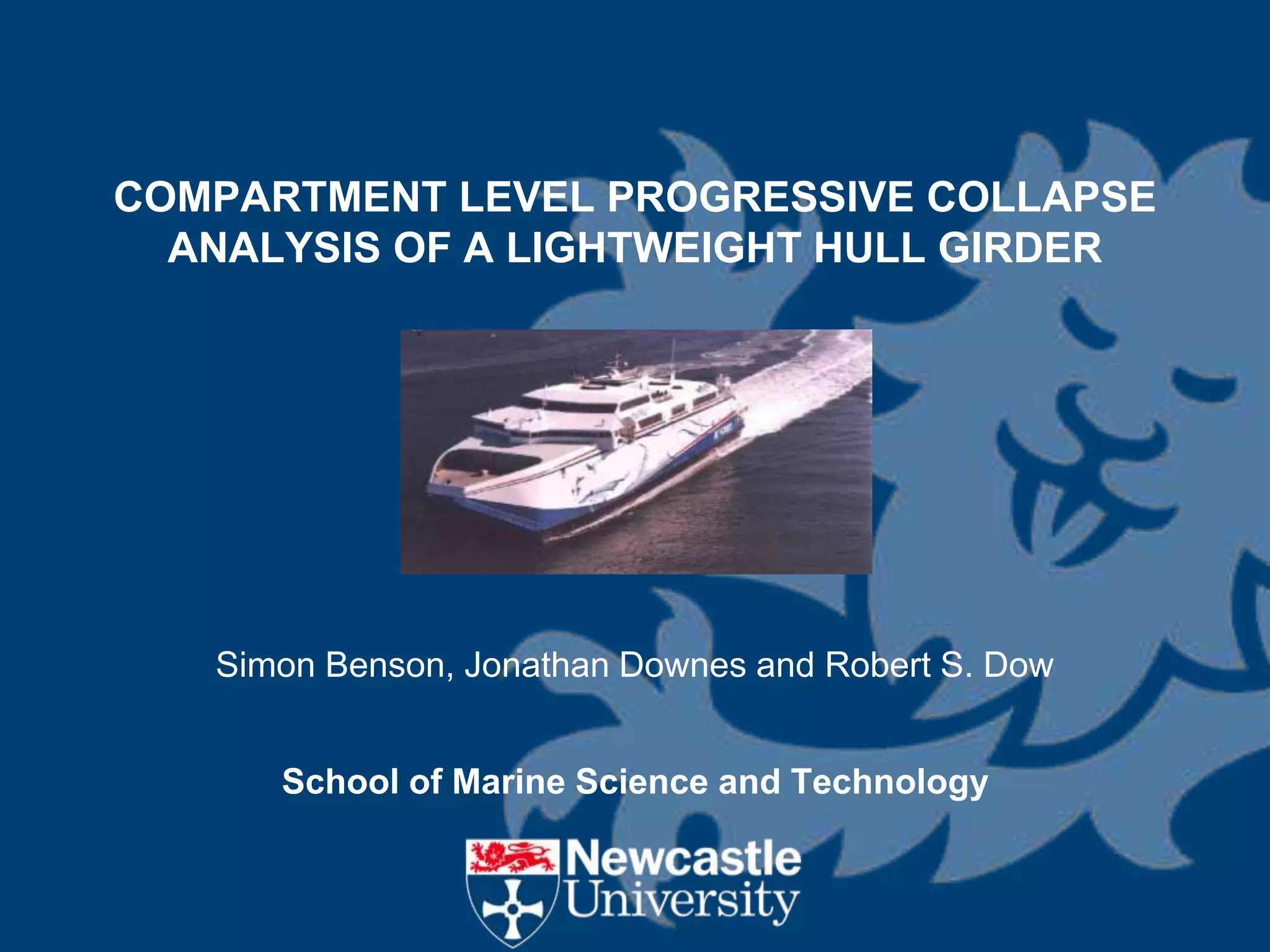
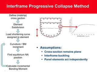
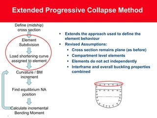
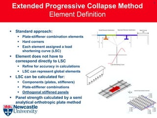
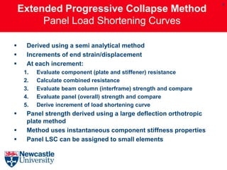
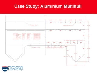
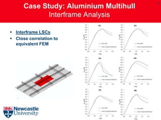
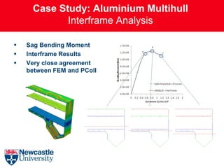
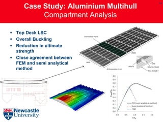
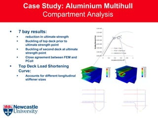
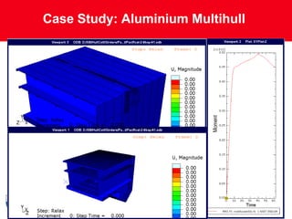
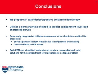
COMPARTMENT LEVEL PROGRESSIVE COLLAPSE
  ANALYSIS OF A LIGHTWEIGHT HULL GIRDER


   Simon Benson, Jonathan Downes and Robert S. Dow


      School of Marine Science and Technology
2


                   Contents

 Motivation

 The Smith Progressive Collapse Method

 The Extended Progressive Collapse Method

 Case Study – Aluminium Multihull

 Conclusions
3


                             Motivation

 Office of Naval Research (ONR) project:
      “Structural Performance of Lightweight Naval Vessels”
 Development and extension of hull girder progressive
  collapse analysis methodologies:
      Ultimate Strength Analysis
      Limit State Design
      Optimisation
      Reliability
      Damage Strength
      Recoverability

 Evaluation of longitudinal bending capacity of the hull girder

 Solution methods:
    Simplified Progressive Collapse Analysis
    Nonlinear Finite Element Analysis
Motivation

 Established hull girder progressive collapse methods have
  been developed primarily for STEEL ships.
 How do we adapt these approaches to lightweight ships?
 Two general approaches:
    Simplified analytical methods (e.g. progressive collapse):
        Fast and efficient
        Simplifying assumptions
        Implicit characterisation of material and geometric imperfections
    Nonlinear finite element methods (FEM):
        Computationally expensive
        Requires explicit characterisation of all material and geometric properties in
         the FE model
 Which methods are suitable for reliability analysis?
Interframe Progressive Collapse Method
                                                                                                                                                                     5083-H116 Plate Load Shortening Curves
  Define (midship)                                                                                                                                                             HAZ Ratio (HR) = 8

   cross section                                                                                                                                    1
                                                                                                                                                   0.9


                                                                                                               Normalised Stress, s' = save / s0
                                                                                                                                                   0.8
                                                                                                                                                   0.7


      Element                                                                                                                                      0.6
                                                                                                                                                   0.5
                                                                                                                                                                                                                             b=2

     Subdivision                                                                                                                                   0.4
                                                                                                                                                   0.3
                                                                                                                                                   0.2
                                                                                                                                                   0.1
                                                                                                                                                    0
Load shortening curve                                                                                                                                     0    0.2      0.4    0.6     0.8       1   1.2   1.4   1.6   1.8   2
                                                                                                                                                                          Normalised strain, e' = e ave / e 0
 assigned to element

   Curvature / BM
     increment           Assumptions:
                           Cross-section remains plane
                                                                      1.50

                                  Bending Moment, Mx (N.mm) x 10-10
                                                                      1.00

 Find equilibrium NA       Interframe buckling                       0.50

       position                                                                                                                                                          hog

                           Panel elements act independently          0.00

                                                                                  sag
                                                                      -0.50                                                                          Progressive Collapse - 150mm hard corners

                                                                                                                                                     Abaqus 5bay model (50mm element size)
                                                                      -1.00
Calculate incremental                                                                                                                                Abaqus 5bay model (25mm element size)


                                                                      -1.50
  Bending Moment                                                          -4.00   -3.00   -2.00     -1.00   0.00                                   1.00       2.00      3.00    4.00

                                                                                                  Curvature, C (1/mm) x 106
Extended Progressive Collapse Method

  Define (midship)
   cross section
                           Extends the approach used to define the
      Element               element behaviour
     Subdivision           Revised Assumptions:
                              Cross section remains plane (as before)
Load shortening curve         Compartment level elements
 assigned to element          Elements do not act independently
                              Interframe and overall buckling properties
   Curvature / BM              combined
     increment


 Find equilibrium NA
       position


Calculate incremental
  Bending Moment
7
    Extended Progressive Collapse Method
              Element Definition

   Standard approach:
      Plate-stiffener combination elements
      Hard corners
      Each element assigned a load
       shortening curve (LSC)
   Element does not have to
    correspond directly to LSC
      Refine for accuracy in calculations
      LSC can represent global elements
   LSC can be calculated for:
      Components (plates, stiffeners)
      Plate-stiffener combinations
      Orthogonal stiffened panels
   Panel strength calculated by a semi
    analytical orthotropic plate method
8
    Extended Progressive Collapse Method
         Panel Load Shortening Curves

     Derived using a semi analytical method
     Increments of end strain/displacement
     At each increment:
     1.   Evaluate component (plate and stiffener) resistance
     2.   Calculate combined resistance
     3.   Evaluate beam column (interframe) strength and compare
     4.   Evaluate panel (overall) strength and compare
     5.   Derive increment of load shortening curve
     Panel strength derived using a large deflection orthotropic
      plate method
     Method uses instantaneous component stiffness properties
     Panel LSC can be assigned to small elements
9
    Extended Progressive Collapse Method
           Implementation - ProColl

    A GUI Interface for the extended
     progressive collapse method
    Interframe and compartment
     level analyses
    Runs vertical bending or
     combinations of vertical and
     horizontal (interaction diagram)
    Increments of curvature or
     bending moment
    Post processor capabilities
       Generate element load
        shortening curves
       Process BM vs. curvature plots
       Graphically display element
        stiffness and NA position
Case Study: Aluminium Multihull
12
      Case Study: Aluminium Multihull
             Interframe Analysis

 Interframe LSCs
 Close correlation to
  equivalent FEM
Case Study: Aluminium Multihull
            Interframe Analysis

   Sag Bending Moment
   Interframe Results
   Very close agreement
    between FEM and PColl
14
     Case Study: Aluminium Multihull
          Compartment Analysis

 Top Deck LSC
 Overall Buckling
 Reduction in ultimate
  strength
 Close agreement between
  FEM and semi analytical
  method
Case Study: Aluminium Multihull
               Compartment Analysis

       7 bay results:
          reduction in ultimate strength
          Buckling of top deck prior to
           ultimate strength point
          Buckling of second deck at ultimate
           strength point
          Close agreement between FEM and
           PColl
       Top Deck Load Shortening
        Curve:
          Accounts for different longitudinal
           stiffener sizes
Case Study: Aluminium Multihull


               16
17


                               Conclusions

   We propose an extended progressive collapse methodology

   Utilises a semi analytical method to predict compartment level load
    shortening curves

   Case study progressive collapse assessment of an aluminium multihull is
    presented:
        Shows significant strength reduction due to compartment level buckling
        Good correlation to FEM results


   Both FEM and simplified methods can produce reasonable and valid
    solutions for the compartment level progressive collapse problem
Thank you

 http://www.ncl.ac.uk/marine/
http://sibenson.wordpress.com

Benson-ASRANET2012

  • 1.
    COMPARTMENT LEVEL PROGRESSIVECOLLAPSE ANALYSIS OF A LIGHTWEIGHT HULL GIRDER Simon Benson, Jonathan Downes and Robert S. Dow School of Marine Science and Technology
  • 2.
    2 Contents  Motivation  The Smith Progressive Collapse Method  The Extended Progressive Collapse Method  Case Study – Aluminium Multihull  Conclusions
  • 3.
    3 Motivation  Office of Naval Research (ONR) project: “Structural Performance of Lightweight Naval Vessels”  Development and extension of hull girder progressive collapse analysis methodologies:  Ultimate Strength Analysis  Limit State Design  Optimisation  Reliability  Damage Strength  Recoverability  Evaluation of longitudinal bending capacity of the hull girder  Solution methods:  Simplified Progressive Collapse Analysis  Nonlinear Finite Element Analysis
  • 4.
    Motivation  Established hullgirder progressive collapse methods have been developed primarily for STEEL ships.  How do we adapt these approaches to lightweight ships?  Two general approaches:  Simplified analytical methods (e.g. progressive collapse):  Fast and efficient  Simplifying assumptions  Implicit characterisation of material and geometric imperfections  Nonlinear finite element methods (FEM):  Computationally expensive  Requires explicit characterisation of all material and geometric properties in the FE model  Which methods are suitable for reliability analysis?
  • 5.
    Interframe Progressive CollapseMethod 5083-H116 Plate Load Shortening Curves Define (midship) HAZ Ratio (HR) = 8 cross section 1 0.9 Normalised Stress, s' = save / s0 0.8 0.7 Element 0.6 0.5 b=2 Subdivision 0.4 0.3 0.2 0.1 0 Load shortening curve 0 0.2 0.4 0.6 0.8 1 1.2 1.4 1.6 1.8 2 Normalised strain, e' = e ave / e 0 assigned to element Curvature / BM increment  Assumptions:  Cross-section remains plane 1.50 Bending Moment, Mx (N.mm) x 10-10 1.00 Find equilibrium NA  Interframe buckling 0.50 position hog  Panel elements act independently 0.00 sag -0.50 Progressive Collapse - 150mm hard corners Abaqus 5bay model (50mm element size) -1.00 Calculate incremental Abaqus 5bay model (25mm element size) -1.50 Bending Moment -4.00 -3.00 -2.00 -1.00 0.00 1.00 2.00 3.00 4.00 Curvature, C (1/mm) x 106
  • 6.
    Extended Progressive CollapseMethod Define (midship) cross section  Extends the approach used to define the Element element behaviour Subdivision  Revised Assumptions:  Cross section remains plane (as before) Load shortening curve  Compartment level elements assigned to element  Elements do not act independently  Interframe and overall buckling properties Curvature / BM combined increment Find equilibrium NA position Calculate incremental Bending Moment
  • 7.
    7 Extended Progressive Collapse Method Element Definition  Standard approach:  Plate-stiffener combination elements  Hard corners  Each element assigned a load shortening curve (LSC)  Element does not have to correspond directly to LSC  Refine for accuracy in calculations  LSC can represent global elements  LSC can be calculated for:  Components (plates, stiffeners)  Plate-stiffener combinations  Orthogonal stiffened panels  Panel strength calculated by a semi analytical orthotropic plate method
  • 8.
    8 Extended Progressive Collapse Method Panel Load Shortening Curves  Derived using a semi analytical method  Increments of end strain/displacement  At each increment: 1. Evaluate component (plate and stiffener) resistance 2. Calculate combined resistance 3. Evaluate beam column (interframe) strength and compare 4. Evaluate panel (overall) strength and compare 5. Derive increment of load shortening curve  Panel strength derived using a large deflection orthotropic plate method  Method uses instantaneous component stiffness properties  Panel LSC can be assigned to small elements
  • 9.
    9 Extended Progressive Collapse Method Implementation - ProColl  A GUI Interface for the extended progressive collapse method  Interframe and compartment level analyses  Runs vertical bending or combinations of vertical and horizontal (interaction diagram)  Increments of curvature or bending moment  Post processor capabilities  Generate element load shortening curves  Process BM vs. curvature plots  Graphically display element stiffness and NA position
  • 10.
  • 11.
  • 12.
    12 Case Study: Aluminium Multihull Interframe Analysis  Interframe LSCs  Close correlation to equivalent FEM
  • 13.
    Case Study: AluminiumMultihull Interframe Analysis  Sag Bending Moment  Interframe Results  Very close agreement between FEM and PColl
  • 14.
    14 Case Study: Aluminium Multihull Compartment Analysis  Top Deck LSC  Overall Buckling  Reduction in ultimate strength  Close agreement between FEM and semi analytical method
  • 15.
    Case Study: AluminiumMultihull Compartment Analysis  7 bay results:  reduction in ultimate strength  Buckling of top deck prior to ultimate strength point  Buckling of second deck at ultimate strength point  Close agreement between FEM and PColl  Top Deck Load Shortening Curve:  Accounts for different longitudinal stiffener sizes
  • 16.
  • 17.
    17 Conclusions  We propose an extended progressive collapse methodology  Utilises a semi analytical method to predict compartment level load shortening curves  Case study progressive collapse assessment of an aluminium multihull is presented:  Shows significant strength reduction due to compartment level buckling  Good correlation to FEM results  Both FEM and simplified methods can produce reasonable and valid solutions for the compartment level progressive collapse problem
  • 18.