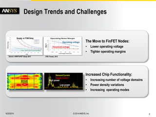
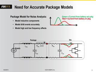
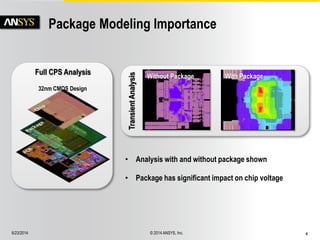
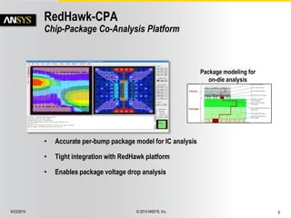
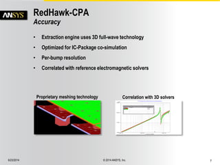
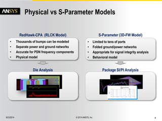
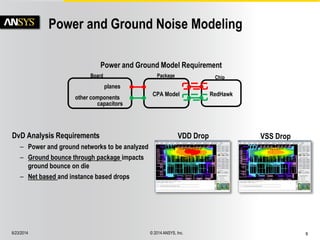
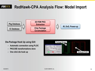
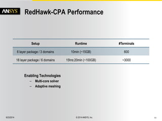
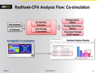
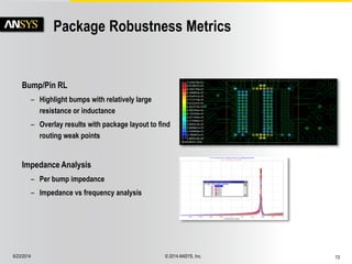
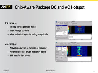
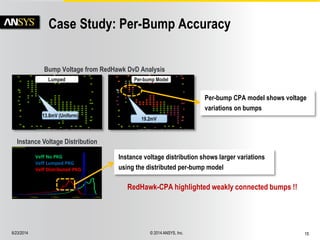
6/23/2014 © 2014 ANSYS, Inc. 1 
RedHawk™-CPA 
Chip-Package Co-analysis 
Design Automation Conference 2014
6/23/2014 © 2014 ANSYS, Inc. 2 
Design Trends and Challenges 
The Move to FinFET Nodes: 
• Lower operating voltage 
• Tighter operating margins 
Increased Chip Functionality: 
• Increasing number of voltage domains 
• Power density variations 
• Increasing operating modes 
Supply vs FOM Delay 
Source: ARM FinFET Study 2013 
Demand Current 
Supply Current 
High power 
Low power 
ITRS Trends, 2012 
Operating voltage 
Threshold voltage
6/23/2014 © 2014 ANSYS, Inc. 3 
Need for Accurate Package Models 
Package Model for Noise Analysis: 
• Model inductive components 
• Model di/dt events accurately 
• Model high and low frequency effects 
Rpkg 
Cpkg 
Lpkg 
Package 
V(t) 
Cdie 
Die 
Rdie 
+ 
- 
Supply 
i(t,V) 
Green = Current from battery w/o pkg 
Red = Current from battery w/ pkg
6/23/2014 © 2014 ANSYS, Inc. 4 
Package Modeling Importance 
Full CPS Analysis 
Transient Analysis 
Without Package With Package 
32nm CMOS Design 
• Analysis with and without package shown 
• Package has significant impact on chip voltage
6/23/2014 © 2014 ANSYS, Inc. 5 
RedHawk-CPA 
Chip-Package Co-Analysis Platform 
• Accurate per-bump package model for IC analysis 
• Tight integration with RedHawk platform 
• Enables package voltage drop analysis 
Package modeling for 
on-die analysis
6/23/2014 © 2014 ANSYS, Inc. 6 
RedHawk-CPA Overview 
• Package Model Generation Customized for RedHawk 
– High bump resolution 
– Model power/ground supplies independently 
– Fast and accurate 
– Automatic hook-up and import into RedHawk 
– Direct import of package layout 
• IC-Package Co-Analysis 
– Support for IR, DvD and power-up analysis in RedHawk 
– DC-IR Static analysis of package 
– AC-hotspot analysis of package
6/23/2014 © 2014 ANSYS, Inc. 7 
RedHawk-CPA 
Accuracy 
• Extraction engine uses 3D full-wave technology 
• Optimized for IC-Package co-simulation 
• Per-bump resolution 
• Correlated with reference electromagnetic solvers 
Proprietary meshing technology Correlation with 3D solvers
6/23/2014 © 2014 ANSYS, Inc. 8 
Physical vs S-Parameter Models 
Die Analysis Package SI/PI Analysis 
RedHawk-CPA (RLCK Model) 
• Thousands of bumps can be modeled 
• Separate power and ground networks 
• Accurate for PDN frequency components 
• Physical model 
S-Parameter (3D-FW Model) 
• Limited to tens of ports 
• Folded ground/power networks 
• Appropriate for signal integrity analysis 
• Behavioral model
6/23/2014 © 2014 ANSYS, Inc. 9 
Power and Ground Noise Modeling 
DvD Analysis Requirements 
– Power and ground networks to be analyzed 
– Ground bounce through package impacts 
ground bounce on die 
– Net based and instance based drops 
VDD Drop VSS Drop 
Board Package Chip 
planes 
capacitors 
other components 
CPA Model RedHawk 
Power and Ground Model Requirement
6/23/2014 © 2014 ANSYS, Inc. 10 
RedHawk-CPA Analysis Flow: Model Import 
RedHawk 
3D FEM PKG 
Pkg Database Extraction 
IC Database Chip Package 
Co-simulation 
IR, DvD, Power-up 
Package Bumps 
RedHawk PLOC 
Die-Package Hook Up using GUI: 
– Automatic connection using PLOC 
– PKG-DIE transformations done 
– One click die hook up
6/23/2014 © 2014 ANSYS, Inc. 11 
RedHawk-CPA Performance 
Setup Runtime #Terminals 
6 layer package / 3 domains 10min (~15GB) 600 
18 layer package / 6 domains 15hrs:20min (~100GB) ~3000 
Enabling Technologies 
– Multi-core solver 
– Adaptive meshing
6/23/2014 © 2014 ANSYS, Inc. 12 
Package-Aware 
IR/DvD 
Chip-Aware Package 
AC/DC Hotspot 
RedHawk-CPA Analysis Flow: Co-simulation 
Package/Die Co-visualization RedHawk Explorer Results 
RedHawk 
3D FEM PKG 
Pkg Database Extraction 
IC Database Chip Package 
Co-simulation 
Package Robustness 
Metrics
6/23/2014 © 2014 ANSYS, Inc. 13 
Package Robustness Metrics 
Impedance Analysis 
– Per bump impedance 
– Impedance vs frequency analysis 
Bump/Pin RL 
– Highlight bumps with relatively large 
resistance or inductance 
– Overlay results with package layout to find 
routing weak points
6/23/2014 © 2014 ANSYS, Inc. 14 
Chip-Aware Package DC and AC Hotspot 
AC-Hotspot 
– AC voltage/current as function of frequency 
– Automatic or user driven frequency points 
– EMI near/far field views 
DC-Hotspot 
– IR drop across package planes 
– View voltage, currents 
– View individual layers including bumps/balls
6/23/2014 © 2014 ANSYS, Inc. 15 
Case Study: Per-Bump Accuracy 
RedHawk-CPA highlighted weakly connected bumps !! 
Bump Voltage from RedHawk DvD Analysis 
Per-bump Model 
19.2mV 
Lumped 
13.8mV (Uniform) 
Veff No PKG 
Veff Lumped PKG 
Veff Distributed PKG 
Instance Voltage Distribution 
Instance voltage distribution shows larger variations 
using the distributed per-bump model 
Per-bump CPA model shows voltage 
variations on bumps
6/23/2014 © 2014 ANSYS, Inc. 16 
Case Study: RedHawk-CPA 
– Not all cores were able to meet specified speed 
– Silicon measurement showed voltage gradient 
across cores to be the cause 
– Simulations with RedHawk-CPA high resolution 
package model correlated with measurement 
• 61mV simulated vs. 50mV measured voltage 
difference (core3 – core1) 
Source: Mahesh Sharma et al., “Unified method for package-induced power 
supply droop”. Design Automation Conference 2013, Designer Track 
Core 
1 
Core 
0 
Core 
3 
Core 
2 
Cores 0/1 faster 
than cores 2/3 
RedHawk-CPA Results 
Silicon Measurements
6/23/2014 © 2014 ANSYS, Inc. 17 
Summary 
Independent Power/Ground 
Analysis with Package 
Package Pin 
Inductance/R Maps 
HTML Report of Analysis 
RedHawk-CPA 
IC Database Pkg Database 
Enabling IC/Package Co-analysis Using RedHawk-CPA 
3D FEM Package 
Extraction 
IR, DvD, Power-up 
Accurate Voltage Gradient 
Across Bumps 
IC-Package 
Co-Analysis 
Streamlined 
Package/Die Setup

ANSYS RedHawk-CPA: New Paradigm for Faster Chip-Package Convergence

  • 1.
    6/23/2014 © 2014ANSYS, Inc. 1 RedHawk™-CPA Chip-Package Co-analysis Design Automation Conference 2014
  • 2.
    6/23/2014 © 2014ANSYS, Inc. 2 Design Trends and Challenges The Move to FinFET Nodes: • Lower operating voltage • Tighter operating margins Increased Chip Functionality: • Increasing number of voltage domains • Power density variations • Increasing operating modes Supply vs FOM Delay Source: ARM FinFET Study 2013 Demand Current Supply Current High power Low power ITRS Trends, 2012 Operating voltage Threshold voltage
  • 3.
    6/23/2014 © 2014ANSYS, Inc. 3 Need for Accurate Package Models Package Model for Noise Analysis: • Model inductive components • Model di/dt events accurately • Model high and low frequency effects Rpkg Cpkg Lpkg Package V(t) Cdie Die Rdie + - Supply i(t,V) Green = Current from battery w/o pkg Red = Current from battery w/ pkg
  • 4.
    6/23/2014 © 2014ANSYS, Inc. 4 Package Modeling Importance Full CPS Analysis Transient Analysis Without Package With Package 32nm CMOS Design • Analysis with and without package shown • Package has significant impact on chip voltage
  • 5.
    6/23/2014 © 2014ANSYS, Inc. 5 RedHawk-CPA Chip-Package Co-Analysis Platform • Accurate per-bump package model for IC analysis • Tight integration with RedHawk platform • Enables package voltage drop analysis Package modeling for on-die analysis
  • 6.
    6/23/2014 © 2014ANSYS, Inc. 6 RedHawk-CPA Overview • Package Model Generation Customized for RedHawk – High bump resolution – Model power/ground supplies independently – Fast and accurate – Automatic hook-up and import into RedHawk – Direct import of package layout • IC-Package Co-Analysis – Support for IR, DvD and power-up analysis in RedHawk – DC-IR Static analysis of package – AC-hotspot analysis of package
  • 7.
    6/23/2014 © 2014ANSYS, Inc. 7 RedHawk-CPA Accuracy • Extraction engine uses 3D full-wave technology • Optimized for IC-Package co-simulation • Per-bump resolution • Correlated with reference electromagnetic solvers Proprietary meshing technology Correlation with 3D solvers
  • 8.
    6/23/2014 © 2014ANSYS, Inc. 8 Physical vs S-Parameter Models Die Analysis Package SI/PI Analysis RedHawk-CPA (RLCK Model) • Thousands of bumps can be modeled • Separate power and ground networks • Accurate for PDN frequency components • Physical model S-Parameter (3D-FW Model) • Limited to tens of ports • Folded ground/power networks • Appropriate for signal integrity analysis • Behavioral model
  • 9.
    6/23/2014 © 2014ANSYS, Inc. 9 Power and Ground Noise Modeling DvD Analysis Requirements – Power and ground networks to be analyzed – Ground bounce through package impacts ground bounce on die – Net based and instance based drops VDD Drop VSS Drop Board Package Chip planes capacitors other components CPA Model RedHawk Power and Ground Model Requirement
  • 10.
    6/23/2014 © 2014ANSYS, Inc. 10 RedHawk-CPA Analysis Flow: Model Import RedHawk 3D FEM PKG Pkg Database Extraction IC Database Chip Package Co-simulation IR, DvD, Power-up Package Bumps RedHawk PLOC Die-Package Hook Up using GUI: – Automatic connection using PLOC – PKG-DIE transformations done – One click die hook up
  • 11.
    6/23/2014 © 2014ANSYS, Inc. 11 RedHawk-CPA Performance Setup Runtime #Terminals 6 layer package / 3 domains 10min (~15GB) 600 18 layer package / 6 domains 15hrs:20min (~100GB) ~3000 Enabling Technologies – Multi-core solver – Adaptive meshing
  • 12.
    6/23/2014 © 2014ANSYS, Inc. 12 Package-Aware IR/DvD Chip-Aware Package AC/DC Hotspot RedHawk-CPA Analysis Flow: Co-simulation Package/Die Co-visualization RedHawk Explorer Results RedHawk 3D FEM PKG Pkg Database Extraction IC Database Chip Package Co-simulation Package Robustness Metrics
  • 13.
    6/23/2014 © 2014ANSYS, Inc. 13 Package Robustness Metrics Impedance Analysis – Per bump impedance – Impedance vs frequency analysis Bump/Pin RL – Highlight bumps with relatively large resistance or inductance – Overlay results with package layout to find routing weak points
  • 14.
    6/23/2014 © 2014ANSYS, Inc. 14 Chip-Aware Package DC and AC Hotspot AC-Hotspot – AC voltage/current as function of frequency – Automatic or user driven frequency points – EMI near/far field views DC-Hotspot – IR drop across package planes – View voltage, currents – View individual layers including bumps/balls
  • 15.
    6/23/2014 © 2014ANSYS, Inc. 15 Case Study: Per-Bump Accuracy RedHawk-CPA highlighted weakly connected bumps !! Bump Voltage from RedHawk DvD Analysis Per-bump Model 19.2mV Lumped 13.8mV (Uniform) Veff No PKG Veff Lumped PKG Veff Distributed PKG Instance Voltage Distribution Instance voltage distribution shows larger variations using the distributed per-bump model Per-bump CPA model shows voltage variations on bumps
  • 16.
    6/23/2014 © 2014ANSYS, Inc. 16 Case Study: RedHawk-CPA – Not all cores were able to meet specified speed – Silicon measurement showed voltage gradient across cores to be the cause – Simulations with RedHawk-CPA high resolution package model correlated with measurement • 61mV simulated vs. 50mV measured voltage difference (core3 – core1) Source: Mahesh Sharma et al., “Unified method for package-induced power supply droop”. Design Automation Conference 2013, Designer Track Core 1 Core 0 Core 3 Core 2 Cores 0/1 faster than cores 2/3 RedHawk-CPA Results Silicon Measurements
  • 17.
    6/23/2014 © 2014ANSYS, Inc. 17 Summary Independent Power/Ground Analysis with Package Package Pin Inductance/R Maps HTML Report of Analysis RedHawk-CPA IC Database Pkg Database Enabling IC/Package Co-analysis Using RedHawk-CPA 3D FEM Package Extraction IR, DvD, Power-up Accurate Voltage Gradient Across Bumps IC-Package Co-Analysis Streamlined Package/Die Setup