Download to read offline
![5
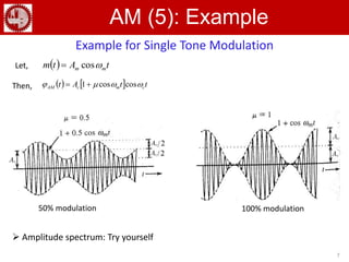
Time Domain of AM (3)
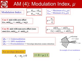
Thus, the carrier component oscillates between the envelope |Ac + m(t)| and its
negative image –|Ac + m(t)|
Envelope of the modulated carrier: e(t) = [Ac + m(t)]
The envelope is an accurate representation of the message, provided -
a. fc >> B, B is the message bandwidth
b. Ac + m(t) > = 0, for all t
Condition a relates to the overlap of the frequency spectrum components
Condition b ensures that the message can be recovered from the envelope
Envelope detection
can be used
Envelope detection
can’t be used](https://image.slidesharecdn.com/forkaneece3094-200328202954/85/Amplitude-Modulation-5-320.jpg)
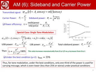
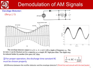
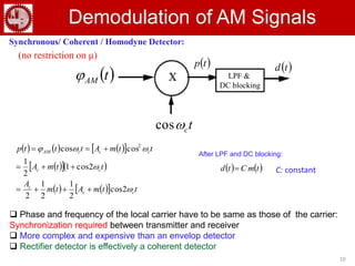

This document discusses amplitude modulation (AM) and its various types. It describes the mathematical equations for double-sideband AM modulation and demodulation. It explains that AM is wasteful of transmitted power and channel bandwidth, but has simpler and less expensive modulators and demodulators compared to other modulation techniques.