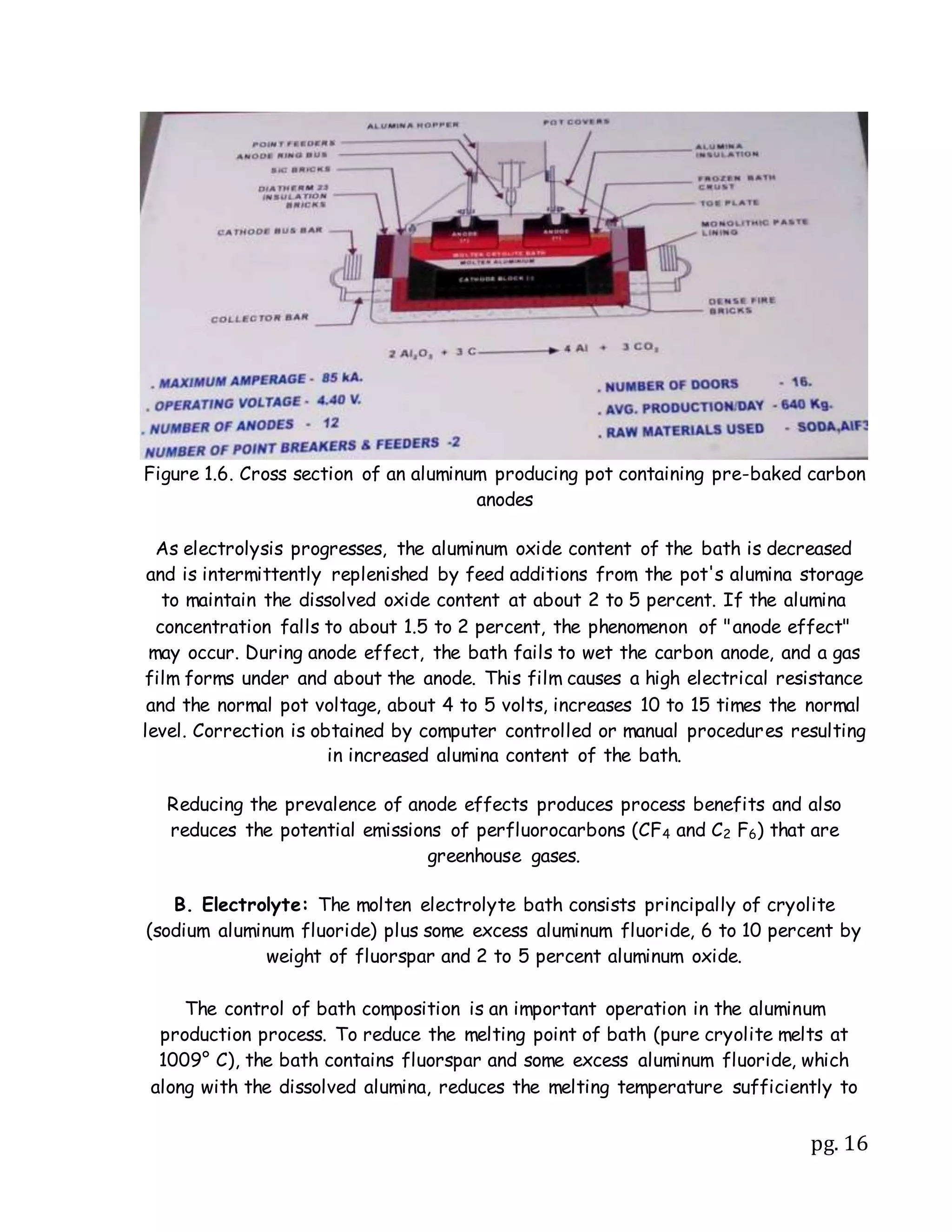
Aluminum is produced through a three step process: 1) mining bauxite ore, 2) refining bauxite into aluminum oxide, and 3) electrolytically reducing aluminum oxide into metallic aluminum. This electrolytic reduction process, known as the Hall-Heroult process, involves dissolving aluminum oxide in a cryolite bath and passing an electric current through it to dissociate the aluminum oxide into molten aluminum and oxygen. Large carbon blocks suspended in the solution serve as the anodes. The process requires significant amounts of electricity and emits carbon dioxide and other gases. Modern aluminum smelters typically include 300-720 electrolytic cells connected in series to continuously produce aluminum through this energy-intensive process.
This presentation is about Extraction of Aluminium. It covers meaning of 'Extraction of Metal', Hall Heroult's process, Bayer's process and Uses of Aluminium. To make such presentations for a reasonably cheaper price, please visit https://sbsolnlimited.wixsite.com/busnedu/bookings-checkout/hire-designer-for-powerpoint-slides
Production of aluminum (emphasis on energy and materials requirements) Thanos Paraschos
Aluminum is produced commercially using Bayer process and Hell- Héroult process. Besides scrap recycling and reuse of aluminum hydroxide contribute to total production. Bauxite is crushed, digested, precipitated, and calcined resulting in alumina. The alumina is then reduced to aluminum by electrolysis. The worldwide Al production is 41.1 million tons in 2010. The global average in energy is consumption is about 15kWh/kg of Al. The production process is energy intensive and used about 3% of global electricity production in 2010.
see more on : thanosparaschos.com
ELECTRIC ARC FURNACE AC (PART 2) The Raw Materials (steel, steelmaking, furna...Matteo Sporchia
A detailed report about the main raw materials used into the Electric Arc Furnace (EAF) based on the latest technologies of iron and steelmaking fields.
The explosion hazard in urea process (1)Prem Baboo
In Urea plant passivation air is used in reactor, stripper and downstream of the all equipments. The reactor liner material used Titanium, Zirconium, SS 316L (urea grade), 2RE-69 and duplex material .except Titanium and Zirconium all stainless steel required more passivation air. In CO2 some quantity of Hydrogen is present about 0.14% to 0.2% . The passivation oxygen and Hydrogen makes explosive mixture. To avoid a fire or explosion in a process vessel is to introduce inert (noncombustible) gases in such a way that there is never a mixture with a combustible concentration in exit of MP vent. Mixtures of fuel, oxygen, and inert gases are not combustible over the entire range of composition. In CO2 stripping process the HP scrubber is the risky vessel and this vessel consisting blanketing sphere, Heat exchanger part and a scrubbing part. With help of triangular diagram that shows the shape of the combustible/noncombustible regions for a typical gaseous mixture of fuel, oxygen, and inert at specified temperature and pressure. Present article how to avoid that combustible rang and how to tackle that gases in CO2 & ammonia stripping process.
Dear Readers,
In this presentation, I have tried to explain main raw material sources of iron making process. Also, with my experience, I have tried to give a concept about the plant engineering related to raw material. I hope that, this presentation will be helpful for young engineers. With this presentation they will get a broad idea about the raw material, based on which they can study more on the subject.
Regards,
Nirjhar.
Aluminium Processing,Properties and Application Cooper Lackay
Aluminium is an element in the boron group with symbol Al and atomic number 13
Aluminium is so called because it is a base of “alum,” which in turn is derived from the Latin for “bitter salt.”
Aluminium is the second most plentiful metallic element on earth; an estimated 8.3% of the earth crust is composed of aluminium.
An MBA dissertation assessing how effective the Leicester Fire and Rescue Service Diva Fire Safety initiative was in reducing fire incidences by reaching out to the Hindu Asian community of Leicester
Triumvirate Environmental's marketing team created a campaign in honor of National Safety Month. This presentation inspects the new tactics tested in this campaign, the results they produced and the plan moving forward.
Traffic safety campaign pitch by and thenvikram sood
With the world's highest deaths due to accidents, we really need to take the cause up on a war footing. And who better to benefit from it but an insurance brand?
In the framework of the implementation of Task 6 of the Project: Modernization and Safety Improvements of the Road Network in Ukraine – Technical Assistance
ALUMINUM
THE 13TH ELEMENT IN THE PERIODIC TABLE OF ELEMENTS
*WHAT IS ALUMINUM?
- Aluminum derives its name from alum. The Latin name for alum is 'alumen' meaning bitter salt.Note on Naming: Sir Humphry Davy proposed the name aluminum for the element, however, the name aluminium was adopted to conform with the "ium" ending of most elements. This spelling is in use in most countries.
Aluminium was also the spelling in the U.S. until 1925, when the American Chemical Society officially decided to use the name aluminum instead.
*WHO DISCOVERED ALUMINUM?
-Hans Christian Oersted
*FACTS ABOUT OERSTED
-Hans Christian Oersted launched a new epoch in science when he discovered that electricity and magnetism are linked.
He showed by experiment that an electric current flowing through a wire could move a nearby magnet.
The discovery of electromagnetism set the stage for the eventual development of our modern technology-based world.
Oersted also discovered the chemical compound piperine and achieved the first isolation of the element aluminum.
ALUMINUM BASIC FACTS:
Symbol: AlAtomic Number: 13Atomic Weight:26.981539Element Classification Basic MetalCAS Number: 7429-90-5
Aluminum Periodic Table Location
Group: 13Period: 3Block: p
ALUMINUM PHYSICAL DATA
State at room temperature (300 K): SolidAppearance: soft, light, silvery white metalDensity: 2.6989 g/ccDensity at Melting Point: 2.375 g/ccSpecific Gravity: 7.874 (20 °C)Melting Point: 933.47 K, 660.32 °C, 1220.58 °F
Boiling Point: 2792 K, 2519 °C, 4566 °FCritical Point: 8550 KHeat of Fusion: 10.67 kJ/molHeat of Vaporization: 293.72 kJ/molMolar Heat Capacity: 25.1 J/mol·KSpecific Heat: 24.200 J/g·K (at 20 °C)
*Uses and properties
-Image explanation
Aircraft fuselages and aluminium foil are just two of the many and varied uses of this element.
-Appearance
Aluminium is a silvery-white, lightweight metal. It is soft and malleable.malleable.
Aluminium Processing,Properties and Application Cooper Lackay
Aluminium is an element in the boron group with symbol Al and atomic number 13
Aluminium is so called because it is a base of “alum,” which in turn is derived from the Latin for “bitter salt.”
Aluminium is the second most plentiful metallic element on earth; an estimated 8.3% of the earth crust is composed of aluminium.
Professional air quality monitoring systems provide immediate, on-site data for analysis, compliance, and decision-making.
Monitor common gases, weather parameters, particulates.
Comparing Evolved Extractive Text Summary Scores of Bidirectional Encoder Rep...University of Maribor
Slides from:
11th International Conference on Electrical, Electronics and Computer Engineering (IcETRAN), Niš, 3-6 June 2024
Track: Artificial Intelligence
https://www.etran.rs/2024/en/home-english/
Deep Behavioral Phenotyping in Systems Neuroscience for Functional Atlasing a...Ana Luísa Pinho
Functional Magnetic Resonance Imaging (fMRI) provides means to characterize brain activations in response to behavior. However, cognitive neuroscience has been limited to group-level effects referring to the performance of specific tasks. To obtain the functional profile of elementary cognitive mechanisms, the combination of brain responses to many tasks is required. Yet, to date, both structural atlases and parcellation-based activations do not fully account for cognitive function and still present several limitations. Further, they do not adapt overall to individual characteristics. In this talk, I will give an account of deep-behavioral phenotyping strategies, namely data-driven methods in large task-fMRI datasets, to optimize functional brain-data collection and improve inference of effects-of-interest related to mental processes. Key to this approach is the employment of fast multi-functional paradigms rich on features that can be well parametrized and, consequently, facilitate the creation of psycho-physiological constructs to be modelled with imaging data. Particular emphasis will be given to music stimuli when studying high-order cognitive mechanisms, due to their ecological nature and quality to enable complex behavior compounded by discrete entities. I will also discuss how deep-behavioral phenotyping and individualized models applied to neuroimaging data can better account for the subject-specific organization of domain-general cognitive systems in the human brain. Finally, the accumulation of functional brain signatures brings the possibility to clarify relationships among tasks and create a univocal link between brain systems and mental functions through: (1) the development of ontologies proposing an organization of cognitive processes; and (2) brain-network taxonomies describing functional specialization. To this end, tools to improve commensurability in cognitive science are necessary, such as public repositories, ontology-based platforms and automated meta-analysis tools. I will thus discuss some brain-atlasing resources currently under development, and their applicability in cognitive as well as clinical neuroscience.
What is greenhouse gasses and how many gasses are there to affect the Earth.moosaasad1975
What are greenhouse gasses how they affect the earth and its environment what is the future of the environment and earth how the weather and the climate effects.
Multi-source connectivity as the driver of solar wind variability in the heli...Sérgio Sacani
The ambient solar wind that flls the heliosphere originates from multiple
sources in the solar corona and is highly structured. It is often described
as high-speed, relatively homogeneous, plasma streams from coronal
holes and slow-speed, highly variable, streams whose source regions are
under debate. A key goal of ESA/NASA’s Solar Orbiter mission is to identify
solar wind sources and understand what drives the complexity seen in the
heliosphere. By combining magnetic feld modelling and spectroscopic
techniques with high-resolution observations and measurements, we show
that the solar wind variability detected in situ by Solar Orbiter in March
2022 is driven by spatio-temporal changes in the magnetic connectivity to
multiple sources in the solar atmosphere. The magnetic feld footpoints
connected to the spacecraft moved from the boundaries of a coronal hole
to one active region (12961) and then across to another region (12957). This
is refected in the in situ measurements, which show the transition from fast
to highly Alfvénic then to slow solar wind that is disrupted by the arrival of
a coronal mass ejection. Our results describe solar wind variability at 0.5 au
but are applicable to near-Earth observatories.
A brief information about the SCOP protein database used in bioinformatics.
The Structural Classification of Proteins (SCOP) database is a comprehensive and authoritative resource for the structural and evolutionary relationships of proteins. It provides a detailed and curated classification of protein structures, grouping them into families, superfamilies, and folds based on their structural and sequence similarities.
Earliest Galaxies in the JADES Origins Field: Luminosity Function and Cosmic ...Sérgio Sacani
We characterize the earliest galaxy population in the JADES Origins Field (JOF), the deepest
imaging field observed with JWST. We make use of the ancillary Hubble optical images (5 filters
spanning 0.4−0.9µm) and novel JWST images with 14 filters spanning 0.8−5µm, including 7 mediumband filters, and reaching total exposure times of up to 46 hours per filter. We combine all our data
at > 2.3µm to construct an ultradeep image, reaching as deep as ≈ 31.4 AB mag in the stack and
30.3-31.0 AB mag (5σ, r = 0.1” circular aperture) in individual filters. We measure photometric
redshifts and use robust selection criteria to identify a sample of eight galaxy candidates at redshifts
z = 11.5 − 15. These objects show compact half-light radii of R1/2 ∼ 50 − 200pc, stellar masses of
M⋆ ∼ 107−108M⊙, and star-formation rates of SFR ∼ 0.1−1 M⊙ yr−1
. Our search finds no candidates
at 15 < z < 20, placing upper limits at these redshifts. We develop a forward modeling approach to
infer the properties of the evolving luminosity function without binning in redshift or luminosity that
marginalizes over the photometric redshift uncertainty of our candidate galaxies and incorporates the
impact of non-detections. We find a z = 12 luminosity function in good agreement with prior results,
and that the luminosity function normalization and UV luminosity density decline by a factor of ∼ 2.5
from z = 12 to z = 14. We discuss the possible implications of our results in the context of theoretical
models for evolution of the dark matter halo mass function.
Slide 1: Title Slide
Extrachromosomal Inheritance
Slide 2: Introduction to Extrachromosomal Inheritance
Definition: Extrachromosomal inheritance refers to the transmission of genetic material that is not found within the nucleus.
Key Components: Involves genes located in mitochondria, chloroplasts, and plasmids.
Slide 3: Mitochondrial Inheritance
Mitochondria: Organelles responsible for energy production.
Mitochondrial DNA (mtDNA): Circular DNA molecule found in mitochondria.
Inheritance Pattern: Maternally inherited, meaning it is passed from mothers to all their offspring.
Diseases: Examples include Leber’s hereditary optic neuropathy (LHON) and mitochondrial myopathy.
Slide 4: Chloroplast Inheritance
Chloroplasts: Organelles responsible for photosynthesis in plants.
Chloroplast DNA (cpDNA): Circular DNA molecule found in chloroplasts.
Inheritance Pattern: Often maternally inherited in most plants, but can vary in some species.
Examples: Variegation in plants, where leaf color patterns are determined by chloroplast DNA.
Slide 5: Plasmid Inheritance
Plasmids: Small, circular DNA molecules found in bacteria and some eukaryotes.
Features: Can carry antibiotic resistance genes and can be transferred between cells through processes like conjugation.
Significance: Important in biotechnology for gene cloning and genetic engineering.
Slide 6: Mechanisms of Extrachromosomal Inheritance
Non-Mendelian Patterns: Do not follow Mendel’s laws of inheritance.
Cytoplasmic Segregation: During cell division, organelles like mitochondria and chloroplasts are randomly distributed to daughter cells.
Heteroplasmy: Presence of more than one type of organellar genome within a cell, leading to variation in expression.
Slide 7: Examples of Extrachromosomal Inheritance
Four O’clock Plant (Mirabilis jalapa): Shows variegated leaves due to different cpDNA in leaf cells.
Petite Mutants in Yeast: Result from mutations in mitochondrial DNA affecting respiration.
Slide 8: Importance of Extrachromosomal Inheritance
Evolution: Provides insight into the evolution of eukaryotic cells.
Medicine: Understanding mitochondrial inheritance helps in diagnosing and treating mitochondrial diseases.
Agriculture: Chloroplast inheritance can be used in plant breeding and genetic modification.
Slide 9: Recent Research and Advances
Gene Editing: Techniques like CRISPR-Cas9 are being used to edit mitochondrial and chloroplast DNA.
Therapies: Development of mitochondrial replacement therapy (MRT) for preventing mitochondrial diseases.
Slide 10: Conclusion
Summary: Extrachromosomal inheritance involves the transmission of genetic material outside the nucleus and plays a crucial role in genetics, medicine, and biotechnology.
Future Directions: Continued research and technological advancements hold promise for new treatments and applications.
Slide 11: Questions and Discussion
Invite Audience: Open the floor for any questions or further discussion on the topic.
2. pg. 2
Chapter-1 Aluminium Smelting
1.1. INTRODUCTION
Aluminium compounds make up 7.3% of the earth's crust, making it the third most
common crustal element and the most common crustal metal on earth. Aluminium
was first produced in 1808. There are three main steps in the process of aluminium
production. First is the mining of aluminium ore, most commonly bauxite, referred
to as bauxite mining. Second is the refining of bauxite into aluminium oxide
trihydrate (Al2 O3), known as alumina, and third is the electrolytic reduction of
alumina into metallic aluminium. The process requires approximately two to three
tonnes of bauxite for the production of one tonne of alumina, and in turn,
approximately two tonnes of alumina is required for making one tonne of aluminium.
Aluminium occupies a special place in extractive metallurgy because it can be
produced as a high-purity product, enabling its special properties to be utilized. It
has many economically attractive applications in the construction sectors, in the
transportation sector, in numerous industrial products, packaging, and containers.
The substitution of aluminium for common materials such as steel, copper, and
certain composites can generate large energy savings over the net life of various
products. It also reduces the production of the greenhouse gas, carbon dioxide,
particularly in transportation applications because lightweight aluminium-intensive
vehicles will use less fuel than conventional vehicles.
In an aluminium smelter, direct current (DC) is fed into a line of electrolytic cells
connected in series. These electrolytic cells are the nerve centre of the process.
While the cells (pots) vary in size from one plant to another, the fundamental
process is identical and is the only method by which aluminium is produced
industrially. It is named the Hall-Heroult process after its inventors.
Each smelting cell is a large carbon-lined metal container, which is maintained at a
temperature of around 960°C and forms the negative electrode (or cathode). The
cell contains an electrolytic bath of molten salt called 'cryolite' (Na3AlF6), into
which a powder of aluminium oxide (Al2O3) is fed and becomes dissolved to form a
solution. Aluminium fluoride (AlF3) is added to maintain the target bath chemistry.
3. pg. 3
Large carbon blocks, made from calcined petroleum coke and liquid coal tar pitch,
are suspended in the solution; and serve as the positive electrode or anode.
The electrical current passes from the carbon anodes via the bath, containing
alumina in solution, to the carbon cathode cell lining. The current then passes to
the anode of the next pot in series. As the electrical current passes through the
solution, the aluminium oxide is dissociated into molten aluminium (Al) and oxygen
(O2). The oxygen consumes the carbon (C) in the anode blocks to form carbon
dioxide (CO2), which is released.
The electrolytic reaction can be expressed as follows: 2 Al2O3 + 3 C → 4 Al + 3 CO2
1.2. HISTORY
A. Chemical displacement
Hans Christian Oersted first heated potassium amalgam with aluminum chloride and
produced tiny pieces of aluminum in 1825. This was twenty years after Sir
Humphrey Davy first named the metal “aluminum.” Davy was the first to use
electrolysis to produce samples of potassium, sodium, strontium, calcium, barium,
magnesium and boron. He tried unsuccessfully for many years to produce aluminum
by electrolysis. Even though he could not isolate it he was convinced that it existed
and named it anyway. (Later, in much of the world, the name was changed to
"aluminium" to be consistent with other metals. In North America the original
spelling is still used.)
Twenty years later Wohler passed aluminum chloride vapor over molten potassium
and managed to produce larger globules of aluminum. Each globule weighed only
between 10 and 15 milligrams.
It was not until 1854 that a French schoolteacher, Henri Sainte-Claire Deville,
substituted cheaper sodium as the reductant. He managed to prepare a small bar
of aluminum. It was so precious that it was displayed next to the Crown Jewels at
the Paris Exposition the next year.
The French Emperor, Napoleon III, financed Deville's work on aluminum. He hoped
that aluminum could be used to make lightweight armor. Napoleon used aluminum
cutlery on special occasions and had an aluminum rattle made for his young son.
The displacement of aluminum from its chloride by a more active metal worked
adequately. It was of course expensive because the sodium or potassium had to be
produced by electrolysis. Aluminum chloride also had to be made from naturally
occurring aluminum compounds and it is a difficult compound to handle. It is volatile
and tends to absorb water, which interferes with the production of aluminum.
4. pg. 4
B. Electrolysis
Then, in the 1880s, a young American student, Charles Martin Hall, became
interested in aluminum. He decided to develop a commercial process for extracting
aluminum using an electric current. In his first experiments he electrolyzed
solutions of aluminum salts in water. All he managed to produce were the gases
hydrogen and oxygen.
He tried electrolyzing molten aluminum oxide. It did not work. The oxide's high
melting point prevented its electrolysis. Hall tried many other substances without
success.
He needed something that would dissolve aluminum oxide producing a solution that
could conduct an electric current, but which would not itself be decomposed.
He began a systematic search of different salts for this purpose. In February
1886 Hall passed a direct current through a solution of alumina dissolved in cryolite
(Na3 AIF6) in a carbon crucible. After several hours he allowed the contents to
solidify. When he broke up the solid he found several small buttons of aluminum.
Within a few weeks Paul Heroult in France had independently produced aluminum by
an almost identical process. Both Hall and Heroult were only 22 years old. Two
years later Karl Bayer developed his process for the extraction of pure aluminum
oxide from bauxite.
In 1888 Hall set up a company to manufacture aluminum. That company later
became known as the Aluminum Company of America or, Alcoa.
The new process made aluminum production so much easier and cheaper that by
1891 the last Deville chemical reduction plant had closed. From only a few tons
annually, five years earlier, production reached well over 300 tons in 1891.
Although Hall and Heroult are credited with the development of the electrolytic
extraction of aluminum, they were not the first to have the idea. Davy, Deville and
Bunsen (of burner fame) all attempted to extract aluminum using electrolysis.
Deville even experimented with electrolysis of cryolite and alumina, but his only
source of electric current was batteries. At that time electrolysis was too
expensive for commercial production. It was Thomas Edison's invention of the
dynamo and its development that made electrical power available to Hall and
Heroult.
C. Other Methods
Given the high energy and other costs associated with the Hall-Heroult process,
over the years the industry has looked at alternative methods of extracting
5. pg. 5
aluminum. Research has explored carbothermal processes, which require
temperatures greater than 2000oC for direct reduction to take place, and
alternatively a process involving electrolysis of anhydrous aluminum chloride.
While such processes have been shown to produce aluminum, for a variety of
technical reasons they have not been translated into viable commercial scale plants.
At the same time considerable effort has been made to improve the efficiency of
the Hall-Heroult process. Before the Second World War the consumption of
electricity in aluminum smelting averaged around 23.3 kilowatt hours per kilo of
metal produced, whereas today, the most efficient pots run at close to 13 kilowatt
hours per kilo.
These improvements owe in part to the computerization of smelting cells, an
improvement that has largely been unrecognized outside the industry.
The computer takes into account the various current operating variables so that
the voltage in the pot is always the best for prevailing conditions.
Other energy saving advances include -
Improvements in bath chemistry to lower both the smelting temperature and
heat losses and to increase the efficiency of the use of electrical current
Improved insulation to reduce heat losses
Improved baking technology for carbon anodes
Reduced carbon anode consumption per kilogram of aluminum produced
1.3. THE PRIMARY ALUMINIUM PRODUCTION PROCESS
All modern primary aluminium smelting plants are based on the Hall-Heroult
process, invented in 1886. Alumina is reduced into aluminium in electrolytic cells, or
pots. The pot consists of a carbon block (anode), formed by a mixture of coke and
pitch, and a steel box lined with carbon (cathode). An electrolyte consisting of
cryolite (Na3AlF6) lies between the anode and the cathode. Other compounds are
also added, among those are aluminium fluoride and calcium fluoride. The latter to
lower the electrolyte's freezing point. This mixture is heated to approximately
9800
C. At this point the electrolyte melts and refined alumina is added. Reduction
of aluminium ions produce molten aluminium metal at the cathode and oxygen at the
anode, which react with the carbon anode itself to produce CO2.
Aluminium smelting process is an electrolysis process, so an aluminium smelter uses
prodigious amounts of electricity. The smelters tend to be located near large
power stations, often hydroelectric ones and near ports since almost all of them
use imported alumina. A large amount of carbon is also used in this process. Once
aluminium is formed, the hot, molten metal is alloyed with other metals to make a
6. pg. 6
range of primary aluminium products with different properties and suitable for
processing in various ways to make end-user products.
It takes about 2 tonnes of bauxite to produce 1 tonne of alumina; and
approximately 2 tonnes of alumina to produce 1 tonne of aluminium.
1.4. ALUMINIUM SMELTING
In an aluminium smelter, direct current (DC) is fed into a line of electrolytic cells
connected in series. These electrolytic cells are the nerve centre of the process.
While the cells (pots) vary in size from one plant to another, the fundamental
process is identical and is the only method by which aluminium is produced
industrially. It is named the Hall-Heroult process after its inventors.
Each cell is a large carbon-lined metal container, which is maintained at a
temperature of around 960°C and forms the negative electrode (or cathode). The
cell contains an electrolytic bath of molten salt called 'cryolite' (Na3AlF6), into
which a powder of aluminium oxide (Al2O3) is fed and becomes dissolved to form a
solution. Aluminium fluoride (AlF3) is added to maintain the target bath chemistry.
Large carbon blocks, made from calcined petroleum coke and liquid coal tar pitch,
are suspended in the solution; and serve as the positive electrode or anode.
The electrical current passes from the carbon anodes via the bath, containing
alumina in solution, to the carbon cathode cell lining. The current then passes to
the anode of the next pot in series. As the electrical current passes through the
solution, the aluminium oxide is dissociated into molten aluminium (Al) and oxygen
(O2). The oxygen consumes the carbon (C) in the anode blocks to form carbon
dioxide (CO2), which is released.
The electrolytic reaction can be expressed as follows: 2 Al2O3 + 3 C → 4 Al + 3 CO2
7. pg. 7
Figure:1.1. Aluminium smelting pots
Aluminium is formed at about 900°C, but once formed has a melting point of only
660°C. In some smelters this spare heat is used to melt recycled metal, which is
then blended with the new metal. Recycled metal requires only 5 percent of the
energy required to make new metal. Blending recycled metal with new metal allows
considerable energy savings, as well as the efficient use of the extra heat
available. When it comes to quality, there is no difference between primary metal
and recycled metal.
The smelting process required to produce aluminium from the alumina is continuous,
the potline is usually kept in production for 24 hours a day year around. A smelter
cannot be easily stopped and restarted. If production is interrupted by a power
supply failure of more than four hours, the metal in the pots will solidify, often
requiring an expensive rebuilding process.
The hot, molten, metallic aluminium obtained in the process sinks to the bottom of
the reduction cell, while the gaseous by-products form at the top of the cell. The
aluminium is siphoned from the bottom of the cell in a process called tapping (done
by rotation every 24 hours), and transported to dedicated casting operations
where it is alloyed; then cast into ingots, billets and other products.
In addition to carbon dioxide, the aluminium smelting process also emits hydrogen
fluoride (HF) an extremely toxic gaseous emission. Fume treatment plants ("FTPs")
are used to capture the hydrogen fluoride and recycle it as aluminium fluoride for
use in the smelting process. During abnormal smelting conditions, known as anode
8. pg. 8
effects, perfluorocarbon ("PFC") gases are emitted. Two PFC compounds are
released during anode effects, namely tetrafluoromethane (CF4) and
hexafluoroethane (C2F6), which have greenhouse gas warming potential of 6,500
and 9,200 times greater than CO2 respectively.
The aluminium smelting process is extremely energy intensive, which is why most
primary aluminium smelters are located where there is ready access to abundant
energy/power resources. It is also a continuous process: a smelter cannot be
stopped and restarted easily. To the contrary, if production is interrupted by a
power outage for more than four hours, the molten aluminium in the cells will
solidify. This is because metallic aluminium is formed at 900°C but, once formed,
has a melting point of only 660°C. When cells 'freeze' in this way, the only
recourse for recovery is to rebuild the smelter.
There are two main types of aluminium smelting technologies, known as Prebake and
Soderberg.
Figure 1.2. Illustrations of Prebake cell (left) and Soderberg cell (right)
The principal difference between them is the type of anode used. Soderberg
technology uses a continuous anode which is delivered to the cell in the form of a
paste, and which bakes in the pot itself. Prebake technology, on the other hand,
uses multiple anodes in each cell. These anodes are pre-baked in a separate facility
and then suspended in the smelting cell.
1.5. SMELTING POT
9. pg. 9
Smelting cell or pot is the furnace where aluminium is produced in hot molten form
from powder alumina.
Industrial production of primary aluminium is carried out in alumina reduction cells
(Hall- Héroult process) adopted in the late nineteenth century, and continues as
the process in commercial use today. The Hall-Héroult process involves the
electrolytic reduction of alumina (Al2 O3) dissolved in a molten cryolite(Na3 AlF6)
bath operating at temperatures about 960 ºC. Carbon anode is consumed in the
reaction that makes CO and CO2. Molten aluminium is reduced at the cathode.
Figure 1.3. prebaked smelting pot
1.6. LAYOUT OF AN ALUMINIUM SMELTING POTS
The Hall-Heroult electrolysis process is the major production route for primary
aluminium. An electrolysis cell is made of a steel shell with a series of insulating
linings of refractory materials. The cell consists of a brick-lined outer steel shell
as a container and support.
Inside the shell, cathode blocks are cemented together by ramming paste. The top
lining is in contact with the molten metal and acts as the cathode. The molten
10. pg. 10
electrolyte is maintained at high temperature inside the cell. The prebaked anode
is also made of carbon in the form of large sintered blocks suspended in the
electrolyte. A single Soderberg electrode or a number of prebaked carbon blocks
are used as anode, while the principal formulation and the fundamental reactions
occurring on their surface are the same.
An aluminium smelter consists of a large number of cell (pots) in which the
electrolysis takes place. A typical smelter contains anywhere from 300 to 720
pots, each of which produces about a ton of aluminium a day, though the largest
proposed smelters are up to five times that capacity. Smelting is run as a batch
process, with the aluminium metal deposited at the bottom of the pots and
periodically siphoned off. Power must be constantly available, since the pots have
to be repaired at significant cost if the liquid metal solidifies.
1.7. POT COMPONENTS
Electrolyte: The electrolyte is a molten bath of cryolite (Na3AlF6) and dissolved
alumina. Cryolite is a good solvent for alumina with low melting point, satisfactory
viscosity, low vapour pressure. Its density is also lower than that of liquid
aluminium (2 vs 2.3 g/cm3
), which allows natural separation of the product from the
salt at the bottom of the cell. The cryolite ratio (NaF/AlF3) in pure cryolite is 3,
with a melting temperature of 1010 °C, and it forms a eutectic with 11% alumina at
960 °C. In industrial cells the cryolite ratio is kept between 2 and 3 to decrease
its melting temperature to 940-980 °C.
11. pg. 11
Figure 1.4. components of pot
Cathode: The carbon lining which forms the pot cavity consists of carbon blocks,
preformed by external manufacturers. These blocks are placed in the steel pot
shell and cemented together with a paste similar to that used in making the blocks.
Thermal insulation consisting of firebrick, vermiculite, or similar materials is
placed between the cavity lining and the steel shell. Large steel bars, serving as
electrical current collectors, are embedded in the bottom portion of the cavity
lining and extend through openings in the shell to connect with the electrical bus
which links one pot to the next.
12. pg. 12
Figure 1.5. pot cathodes
Carbon pot linings normally last from 4 to 6 years. When failure of a lining occurs,
usually via the penetration of aluminum metal through to the cathode collectors,
the collectors dissolve. Then, the metal and sometimes the fused cryolite bath leak
around the collectors. A sudden increase in iron levels in the aluminum usually
indicates that a pot is nearing the end of its service life. The lining must then be
repaired at the point(s) of failure by a procedure called "patching", or else the
entire lining, insulation, and collector assembly is replaced. The latter procedure is
called "relining". Pot patching and pot relining are a significant part of the
production expense.
Anode: Carbon anodes are a major requirement for the Hall-Heroult process.
About 0.5 tons of carbon is used to produce every ton of aluminum. There are two
main types of carbon anode used. Both types are made from the same basic
materials and react in the same way.
A mixture of petroleum coke and pitch is strongly heated causing the pitch to bind
the coke particles together. "Pre-baked" anodes are made before they are added
to the pot, but "Soderberg" anodes are actually formed and baked in the pot.
13. pg. 13
The Soderberg anode uses the waste heat of reaction in each pot to pyrolyze the
coke and pitch. As the lower part of the anode is consumed in the reaction, more
raw materials are added at the top. During the baking process many volatile
products are driven off as the pitch hydrocarbons are dehydrogenated. Solid
carbon is left as the anode.
Although the Soderberg anode may be more energy efficient it is easier to treat
the volatile wastes if they are not mixed with the other emissions from the pot.
Dehydrogenation is often less complete in the Soderberg anode causing more
hydrogen fluoride to be formed during the anode reaction. So, for environmental
reasons, modern smelters use prebaked anodes.
Prebaked Anodes: In prebaked technology the anodes used are termed as
prebaked anodes which are made from a mixture of petroleum coke, aggregate and
coal tar pitch binder moulded into blocks and baked in separate anode baking
furnace at about 1120 °C. Prebaked anodes consist of solid carbon blocks with an
electrically conductive rod (e.g. copper) inserted and bonded in position usually with
molten iron. An aluminium rod with iron studs is then cast or rammed into grooves
in the top of the anode block in order to support the anode and conduct the
electric current to the anode when it has been positioned in the cell. Prebaked
anodes have to be removed at regular intervals, when they have reacted down to
one third or one fourth of their original size. These remaining anodes are termed
as butts and are usually cleaned outside the cell in a separate cleaning station to be
able to recirculate the adhering bath materials removed from the cell. The cleaned
butts are then crushed and used as a raw material in the manufacturing of new
anodes.
The carbon block consists of high purity calcined petroleum coke and the crushed
remnants of used anode blocks bound together with pitch. The petroleum coke
usually used is a by-product of petroleum refining. Its purity is important as the
carbon is actually consumed in the electrolytic reaction. Any impurities present in
the finished anode can pass into the metal in the smelting cell. Separating the
crushed spent anode material by size allows different sized particles to be mixed
so that the greatest density of packing is achieved.
The component materials are mixed together in heated containers to enable the
melted pitch to blend completely with the coke particles. The resulting "green"
mixture is weighed accurately and formed into the required anode shape.
14. pg. 14
The green anodes are delivered to in-ground baking furnaces, which consist of a
series of refractory brick lined pits with hollow, surrounding interconnected flue
walls.
Anodes are packed into the pits with a blanket of coke covering the anodes and
filling the space between the anode blocks and the walls of the pits. The coke
often used is termed fluid coke and consists of small spherical coke particles the
size of fine sand. Appropriately sized petroleum coke can also be used.
The pits are heated with natural gas for a period of several days. The flue system
of the furnace is arranged so that hot gas from the pits being fired is drawn
through the next few sections of pits to preheat the next batch of anodes before
they are fired. Air for combustion of the gas travels through the flues of
previously fired sections, cooling these anodes while reheating the air. The anodes
are fired to approximately 1150°C, and the cycle of placing green anodes,
preheating, firing, cooling, and removal is approximately two weeks.
The so called "ring" type furnace uses flues under draft, and since the flue walls
are of dry type construction, volatile materials released from the anodes during
the baking cycle are drawn into the flues. Once in the flues they burn, providing
additional heat.
The baked anodes are removed from the furnace pits by means of an overhead
crane on which pneumatic systems for loading and removing the pit packing coke
may also be mounted.
Because the crushed, recycled anode component of a new anode has taken up
fluorides during its life in the pot environment, this gives rise to a potential
emission of fluorides to air during the baking process. Scrubbing equipment traps
these additional fluorides for return to the smelting process.
Cleaned baked anode blocks are transferred from the bake plant storage area by
conveyors to the rodding area to be made into rodded anode assemblies.
1.8. THE HALL-HEROULT SMELTING PROCESS
A. The Process at Work: Simply, the Hall-Heroult process is the method by
which alumina is separated into its component parts of aluminum metal and oxygen
gas by electrolytic reduction. It is a continuous process with alumina being
dissolved in cryolite bath material (sodium aluminum fluoride) in electrolytic cells
called pots and with oxidation of the carbon anodes. The bath is kept in its molten
state by the resistance to the passage of a large electric current. Pot
15. pg. 15
temperatures are typically around 920°- 980°C. The aluminum is separated by
electrolysis and regularly removed for subsequent casting. The pots are connected
electrically in series to form a ‘potline.’
In each pot, direct current passes from carbon anodes, through the cryolite bath
containing alumina in solution, to the carbon cathode cell lining and then to the
anodes of the next pot and so on (see Figure 1.1). Steel bars embedded in the
cathode carry the current out of the pot while the pots themselves are connected
through an aluminum bus-bar system. The pot consists of a steel shell in which the
carbon cathode lining is housed. This lining holds the molten cryolite and alumina in
solution and the molten aluminum created in the process. An electrically insulated
superstructure mounted above the shell stores alumina automatically delivered via
a sealed system and holds the carbon anodes, suspending them in the pot.
The electrolyte, which fills the space between the anodes in the pot, consists of
molten cryolite containing dissolved alumina. A solid crust forms at the surface of
the electrolyte. The crust is broken periodically and alumina is stirred into the
electrolyte to maintain the alumina concentration.
As the electrolytic reaction proceeds, aluminum which is slightly denser than the
pot bath material is continuously deposited in a metal pool on the bottom of the pot
while oxygen reacts with the carbon material of the anodes to form oxides of
carbon. As the anodes are consumed during the process, they must be continuously
lowered to maintain a constant distance between the anode and the surface of the
metal, which electrically is part of the cathode. The anodes are replaced on a
regular schedule.
The vigorous evolution of carbon dioxide at the anode helps mix the added alumina
into the electrolyte but carries off with it any other volatile materials and even
some fine solids. If any carbon monoxide does form it usually burns to carbon
dioxide when it contacts air at the surface of the crust. Compounds of fluoride
formed in side reactions are the other main volatile product. Approximately 13 -16
kilowatt-hours of direct current electrical energy, one half kilo of carbon, and two
kilos of aluminum oxide are consumed per kilo of aluminum produced.
16. pg. 16
Figure 1.6. Cross section of an aluminum producing pot containing pre-baked carbon
anodes
As electrolysis progresses, the aluminum oxide content of the bath is decreased
and is intermittently replenished by feed additions from the pot's alumina storage
to maintain the dissolved oxide content at about 2 to 5 percent. If the alumina
concentration falls to about 1.5 to 2 percent, the phenomenon of "anode effect"
may occur. During anode effect, the bath fails to wet the carbon anode, and a gas
film forms under and about the anode. This film causes a high electrical resistance
and the normal pot voltage, about 4 to 5 volts, increases 10 to 15 times the normal
level. Correction is obtained by computer controlled or manual procedures resulting
in increased alumina content of the bath.
Reducing the prevalence of anode effects produces process benefits and also
reduces the potential emissions of perfluorocarbons (CF4 and C2 F6) that are
greenhouse gases.
B. Electrolyte: The molten electrolyte bath consists principally of cryolite
(sodium aluminum fluoride) plus some excess aluminum fluoride, 6 to 10 percent by
weight of fluorspar and 2 to 5 percent aluminum oxide.
The control of bath composition is an important operation in the aluminum
production process. To reduce the melting point of bath (pure cryolite melts at
1009° C), the bath contains fluorspar and some excess aluminum fluoride, which
along with the dissolved alumina, reduces the melting temperature sufficiently to
17. pg. 17
permit the pots to be operated in the 920° to 980°.C range. The reduced operating
temperature improves pot efficiency.
The weight ratio of sodium fluoride/ aluminum fluoride in cryolite is 1.50; the
excess aluminum fluoride in the electrolyte is adjusted to yield a sodium
fluoride/aluminum fluoride ratio in the 1.00 to 1.40 range by weight.
In the first few weeks after a newly lined pot is placed in operation, the
electrolyte is rapidly absorbed into the lining and insulation with a marked
preferential absorption of a high-sodium- containing portion, tending to reduce the
sodium fluoride/aluminum fluoride ratio below that desired. Compensation for this
is made by adding soda ash.
After the first few weeks of operation the electrolyte tends to become depleted
of aluminum fluoride through volatilization of aluminum fluoride rich compounds,
through reaction with residual caustic soda in the alumina, and, through hydrolysis
from moisture in the air or added materials to give hydrogen fluoride.
C. Fluoride Recovery: Gases and solids evolved from the pot and its electrolyte
are controlled by various treatment processes. The most efficient of the
commercially used methods is the Alcoa A398 Process that utilizes a highly
effective pot hooding system and removes more than 99 percent of the fluoride
emission from the captured pot gases. The A398 Process prevents air pollution,
conserves valuable resources for recycling and, because it is a dry process, there
are no liquid wastes to be disposed of.
Fluoride gases are passed through a bed of alumina where fluoride is adsorbed.
The particulate matter is then collected in a fabric filter baghouse. The reacted or
fluoride-containing alumina is recycled into the aluminum production process.
Relatively small amounts of fluoride are able to escape from the smelting process,
typically during operations such as anode changing when sections of pot hooding are
removed. These emissions are subject to E. P .A. discharge licenses. Continual
efforts are made to improve work practices and processes to keep these emissions
to a minimum.
At Alcoa operated plants, a regular check on the efficiency of emission control
equipment is made by plant technical staff using a range of laboratory based and
portable equipment.
1.9. CALCULATION OF PRODUCTION AND ENERGY EFFICIENCY OF POT
Production Efficiency
18. pg. 18
For a smelting cell of 100 percent efficiency just maintained at the reaction
temperature a theoretical production number can be calculated.
Avogadro's number = 6.0221 X 10
23
Elementary charge = 1.6022 x 10
-19
Coulombs
These numbers give the accepted value for a "Faraday" of:
One Faraday = 96485 Coulombs
Atomic weight of aluminum = 26.9815
Valence of aluminum = 3
One-gram equivalent weight contains Avogardro's number of atoms.
It takes 3 electrons to liberate one atom of aluminum.
Therefore every Faraday liberates 26.9815/3 grams of aluminum.
Therefore, if "I" is the current through a smelting cell, and all of this current
produces aluminum, then in 24 hours every such cell makes:
(Ix24x60x60/96485) x (26.9815/3)/1000 kilograms of aluminum
Say the current is 180,000 amperes (typical of many smelters); then the
theoretical production per cell as predicted by Faraday's Law is 1450
kilograms/day.
However, owing to electrical shorting and other electrolytic reactions and a certain
amount of reoxidation of aluminum, this theoretical production is not realized. In
practice the term "current efficiency" is used, this being the percentage of the
current that actually results in aluminum produced.
In practice, current efficiency is generally in the order of 90 -95% so that:
Actual production per cell = Theoretical Production x CE/100.
Therefore, for example, the actual production in a 180,000 ampere cell at 90%
current efficiency over 24 hours would be 1450x90/100 kilograms; i.e. 1305
kilograms.
A simplified equation for daily cell production is, therefore
Production per cell per day = (Current x CE/100 x 0.008054) kilograms
Energy Efficiency
19. pg. 19
If energy consumption is to be taken into account, then knowledge of the operating
voltage of the cell is required. An estimate of this for some cells would be 4.5
volts.
The above production would therefore occur with a (DC) energy consumption of
180000 x 4.5 x 24/1000 kilowatt-hours.
The electrical energy consumption per unit mass under the preceding scenario
would be
(Current x Volts x 24/1000)/(Daily Production)
= (Current x Volts x 24/1000)/(Current x CE/100 x 0.008054)
So, kWH/kg = Volts/CE x 298 kilowatt-hours/kilogram
With the numbers given, the energy efficiency is 14.9 kWH/kg, although the most
efficient plants would achieve numbers between 13 and 14 kWH/kg.
Most modern plants consist of one to six potlines, each potline consisting of 100 to
300 individual cells connected in series.
1.10. AVERAGE PRODUCTION PER DAY
Alumina powder feeding is done in every 4 minutes.
In every feeding 1.8 kg powder is fed through a single feeder.
Every pot has 2 feeders. i.e. in every 4 minutes 3.6 kg powder is fed to a single pot.
In one hour powder feeding
3.6 * 60/4 = 3.6 * 15 = 54 kg
Per day powder feeding to a single pot
54 * 24 = 1296 kg
Daily aluminium production from a single pot 640 kg.
Hindalco has 720 working pots
Daily powder feeding
20. pg. 20
1296 * 720 = 933120 kg
Daily aluminium production
640 * 720 = 460800 kg
1.11. POT ABNORMALITY
There are different pot abnormalities those create problems in aluminum
production. They are,
1. Side covering missing: Due to this anode erosion takes place, carbon dusting
increases and pot cooling starts.
2. Pot voltage fluctuation: If the pot voltage exceeds 100milli volt then pot
shaking starts and if it is less than 100milli volt then noise occurs.
3. Pot temperature fluctuation: Generally the pot temperature should be
maintained 9600
c. The allowable tolerance is +- 10. If the temperature
exceeds this range then the production decreases.
4. Bath and metal height: Bath and metal height is another important issue
for aluminum production. The bath height should be maintained 16-18 cm and
the metal height should be maintained 14-16 cm. If the bath height
increases then the pot temperature increases and if the metal height
increases then the bath height decreases and pot cooling starts.
5. Bath ratio: The bath ratio should be maintained as 1.16.
6. Current distribution: The current distribution should be proper. The pot
current should be maintained 85kamp.
7. Clamping: Loose clamping may lead to sparking.
22. pg. 22
POINT FEEDER
Chapter-2 POINT FEEDER
Point feeder is the device through which the powder alumina is fed to the smelting
cell (pot). The feeder is a fully pneumatic component which works on compressed
air.
23. pg. 23
2.1. FUNCTIONAL UNITS
A feeder has the following functional units
1) Cylinder assembly
2) Clevis
3) Guide cylinder
4) Cone assembly
Figure 2.1. point feeder components
There is a cylinder assembly at the top of the point feeder which is operated by
compressed air at a pressure of 7 bar .There is one inlet and return channel at the
top and bottom head of the cylinder respectively. The cylinder assembly is mainly
responsible of the movement of the cone assembly for feeding purpose. (Each
feeding nearly 1.8 kg of powder is charged)
The clevis consists of a male clevis and a female clevis connected to each other
through a clevis pin.
The hopper is the chamber in which the alumina powder is stored, and is refilled
through air slide channels at regular intervals.
2.2. WORKING
The feeder is a fully pneumatic component operated on compressed air. A breaking
hole is present in the smelting cell through which the powder alumina is fed in to
24. pg. 24
the pot. The feeder is present just above the hole. The powder is first carried to
the feeder through the channels and the feeder feds the powder alumina directly
into the hole.
Figure 2.2. point feeder
The feeder has two ports one for air intake and the other for air return at the top
head and the bottom head of the cylinder respectively. The piston has a piston rod
which is connected to another rod inside the guide tube. The guide tube provides
support to the piston rod assembly and has sealing elements to avoid air leakage to
the opposite side of the piston. The piston rod assembly is connected to a cone at
the bottom of the guide tube. The cone is provided to open and close the feeder
passage for feeding the alumina powder.
The whole process is digitalized and operated by computerized systems (EPC-
Electronic process control) . There is a definite time interval for the cyclic feeding
process which is preset in the computer. Here the time interval for feeding is set
as 4 minutes (i.e. feeding will be done in the feeder in every 4 minutes).
When the compressed air is supplied through the inlet channel, the piston moves
towards the bottom head which provides a forward movement to the piston rod and
25. pg. 25
as a result the cone connected at the bottom is pushed downward and closes the
powder passage. At that time the alumina powder is fed to the feeder through the
hopper.
At the return stroke when the piston moves upward the cone is dragged up and the
alumina powder present inside the feeder is fed to the feeding hole of the
smelting cell (pot).
Both for the feeder and the breaker the air pressure is given as 75psi.
Here every single pot has two point feeders placed at one line. The feeding is done
in every 4 minutes and in every feeding 1.8 kg alumina powder enters into the pot.
The feeding timing and feeding amount has been preset and controlled through the
computerized system.
2.3. FEEDER PROBLEMS
Feeding is done continuously, so some problems arise in the point feeder.
1. Seal failure (cone failure)
2. Piston sticking
27. pg. 27
PNEUMATIC CRUST
BREAKER
Chapter-3 PNEUMATIC CRUST BREAKER
Crust breaker is a pneumatic device used for breaking. Here breaking means
clearing the path for the feeding of alumina powder. So the crust breaker clears
the path for the alumina powder to enter into the pot and take part in the
electrolysis process.
The crust breaker and the point feeder both work in a cyclic manner. First the
crust breaker clears the hole for the feeding of alumina powder and then the
feeder feeds the powder.
3.1. COMPONENTS
The crust breaker mainly comprises of heat resistive pneumatic cylinder, hammer
and guide pipe. Other components are,
1) Cylinder and piston assembly
28. pg. 28
2) Clevis
3) Hammer
4) Guide pipe
3.1.1. Cylinder and Piston Assembly
The cylinder and piston assembly consists of the cylinder, piston, piston rod, top
head, magnets, bottom head, return tube, long and short studs and middle support.
The cylinder has a bore of diameter 125mm and a stroke of length 550mm.
The upper head of the cylinder is called top head and the lower head of the
cylinder is called bottom head.
The air enters into the cylinder through the inlet channel present at the top head
of the cylinder. This air pressure pushes the piston downward. The piston rod is
connected with the hammer through the clevis. As the piston moves towards the
bottom head it pushes the hammer downward and breaking occurs.
The air flow for cylinder operation is controlled by solenoid valve (5/2 or 4/2
poppet valves)
29. pg. 29
Figure 3.1. cylinder and piston assembly of pneumatic crust breaker
There is a hollow return tube through which the air pushes the piston back to the
top head.
10 small magnets are fitted at the top head in order to hold the piston after the
breaking. Once breaking has been completed there is a definite time gap after
which breaking continues again and this cyclic process goes on. The magnets are
used for holding the piston at the top head in that gap period, i.e. it holds the
piston at the top head after breaking finishes in the first cycle upto the beginning
of breaking at the second cycle. As breaking is done in every four minutes the
magnets hold the piston at the top head for 4 minutes.
There are four long and four short studs at the sides of the cylinder for providing
support to the cylinder. They are connected to each other through the middle
support.
A gland follower is fitted below the bottom head of the cylinder for preventing air
and oil leakage.
30. pg. 30
For the lubrication of the parts lubricating oil is supplied along with the
compressed air. The cylinder is made of heat resistive materials to sustain the
high heat produced (9600
c) inside the smelting cell (pot).
3.1.2. Clevis
Clevis is the connector which connects the piston rod and the hammer. It plays a
very crucial role in transmitting the motion smoothly from the cylinder to the
hammer.
There are two types of clevis for connecting the shafts, i.e. the male clevis and the
female clevis and together they transmit motion. The female clevis is attached to
the piston rod and the hammer contains the male clevis. Both the male and female
clevis are connected to each other with the help of clevis pin to transmit the
constrained motion from the cylinder to the hammer.
3.1.3. Hammer
Hammer is that part of the crust breaker which comes in contact with the hole and
breaks the powder and clears the path for feeding alumina powder.
Figure 3.2. Hammer attached in crust breaker
The hammer is connected with the piston rood of the crust breaker through the
clevis. The hammer is a hollow cylinder. A hammer bit is welded at the edge of the
hammer. The tip of the hammer bit is made cone shaped for ease in operation.
After use when the hammer bit becomes unusable the whole hammer is changed.
31. pg. 31
Figure 3.3. crust breaker assembly
3.1.4 Guide Tube
The guide tube is the cylinder covering the piston rod, clevis and the hammer. The
guide tube smoothens the motion of the hammer by protecting it from vibration.
The guide tube is also made of heat resisting material to sustain the high heat
produced inside the pot.
Figure 3.4. guide tube
32. pg. 32
3.2. WORKING
The air enters into the crust breaker cylinder through a small inlet channel present
at the top head. The pressure of this compressed air pushes the piston downward
towards the bottom head. As the piston moves towards the bottom head the
hammer attached to the piston rod moves downward and breaking takes place.
After breaking the air returns through the return pipe and the piston returns to
the top head thus the cyclic process goes on.
There are 10 magnets fitted at the top head for holding the piston. Breaking is a
cyclic process and there is a definite time interval between the first cycle to the
next cycle. The magnets hold the piston in this time interval. Here breaking is done
in every 4 minutes so the magnet holds the piston at the top head for this 4
minutes.
3.3. BREAKER PROBLEMS
1. Gland leakage
2. Tophead leakage
3. Bucket leakage
4. Hammer bit damage
34. pg. 34
Chapter-4 Anode Jack
In a smelting pot anode jack is used for lifting the anode up and downward i.e. for
adjusting the height of the anode. It is also called as pot jack.
The anode is made of carbon. As the anode is used the lower part of the anode is
consumed in the reaction. Due to which there are chances that the anode may not
come in contact with the molten metal and the electrolysis process may stop. To
eliminate this problem aluminium smelters are provided with anode jacks.
There are 12 anode beams on both sides of a prebake pot and 2 anode buses on two
sides to hold 6 anode beams on each side. There are 4 jacks in a pot and are
connected to the anode bus. In case of requirement the jacks lift the bus bar as a
result of which all the anodes are lifted at a time.
The anode jacks are operated electrically. After tapping whenever the molten
metal level inside the pot decreases the anode jack is automatically adjusted and
the beams moves downward to continue the process.
4.1. COMPONENTS
The anode jack assembly has the following components;
35. pg. 35
1. Motor
2. Intermediate shaft
3. Jack
Figure 4.1. anode jack
4.1.1. Motor
The motor is the prime source from which the entire operation of anode jack
starts. There is a motor fitted at one end of the pot. The motor provides motion to
the intermediate shaft. The shaft connected to the motor is the driving shaft and
the intermediate shafts are the driven shafts. The motion of the driving shaft is
transmitted to the intermediate shafts through worm and worm wheel
arrangement.
4.1.2. Intermediate shaft
The intermediate shaft is the medium of transmission motion from the motor to
the jack. The intermediate shaft is divided into two parts, the long shaft and the
short shaft. There are 4 gear boxes, which connect the shafts. Among which two
of them have bevel gear arrangement and the other two have worm gear
arrangement. The two bevel gears are used to transmit the motion form the driving
shafts to the short shafts at 900
angle. The short shafts are connected to the long
shafts by worm gear arrangement. The rotational motion of the shaft is converted
to translational motion of the jack and it lifts the anode bus.
36. pg. 36
4.1.3. Jack
There are 4 jacks in a single pot, two on each side. The bus is clamped to the jack.
As the shaft rotates the rotational motion is converted to translational motion at
the jack due to which the anode bus is lifted up and downward.
Figure 4.2. anode jack assembly in a pot
4.2. OPERATION
When the motor switch is on the driving or motor shaft rotates. The driving shaft
is connected to the short intermediate shaft through bevel gear arrangement. So
the motion of the driving shaft provides motion to the short intermediate shaft.
The short intermediate shaft is connected to the long intermediate shaft through
worm gear arrangement. So when the short shaft rotates the long shaft also
rotates simultaneously. The jacks are connected to the long intermediate shaft at
its two ends. The jacks hold the anode bus.
37. pg. 37
The rotational motion of the intermediate shafts is converted to reciprocating
motion of the anode jack as a result of which it moves up and down resulting in
raising and lowering of anodes.
39. pg. 39
Chapter-5 Compressor
Compressors are widely used in industries to transport fluids. It is a mechanical
device that compresses a gas.
Generally, the compression of gases may be accomplished in device with rotating
blades or in cylinders with reciprocating pistons. There are many types of
compressors, thus a proper selection is needed to fulfil the typical necessity of
each industry.
5.1. TYPES OF COMPRESSORS
Compressor is a device used to increase the pressure of compressible fluid, either
gas or vapor, by reducing the fluid specific volume during passage of the fluid
through compressor.
One of basic aim of compressor usage is to compress the fluid, then deliver it to a
higher pressure than its original pressure. The inlet and outlet pressure level is
varying, from a deep vacuum to a high positive pressure, depends on process’
necessity. This inlet and outlet pressure is related, corresponding with the type of
compressor and its configuration.
compressors are generally classified into two separate and distinct categories:
dynamic and positive displacement.
40. pg. 40
5.1.1. DYNAMIC COMPRESSOR
Dynamic compressor is a continuous-flow compressor which includes centrifugal
compressor and axial flow compressor. It is widely used in chemical and petroleum
refinery industry for specifies services. They are also used in other industries
such as the iron and steel industry, pipeline booster, and on offshore platforms for
reinjection compressors.
The dynamic compressor is characterized by rotating impeller to add velocity and
pressure to fluid. Compare to positive displacement type compressor, dynamic
compressor are much smaller in size and produce much less vibration.
(i) Centrifugal Compressor
The centrifugal compressor is a dynamic machine that achieves compression by
applying inertial forces to the gas (acceleration, deceleration, and turning) by
means of rotating impellers.
It is made up of one or more stages; each stage consists of an impeller as the
rotating element and the stationary element, i.e. diffuser.
There are two types of diffuser: vaneless diffusers and vaned diffusers.
Vaneless diffuser is widely used in wide operating range applications, while the
vaned diffuser is used in applications where a high pressure ratio or high
efficiency is required.
The parts of centrifugal compressor are simply pictured below.
Figure 5.1. Centrifugal compressor
41. pg. 41
In centrifugal compressor, the fluid flow enters the impeller in an axial direction
and discharged from an impeller radially at a right angle to the axis of rotation.
The gas fluid is forced through the impeller by rapidly rotating impeller blades.
The gas next flows through a circular chamber (diffuser), following a spiral path
where it loses velocity and increases pressure.
The deceleration of flow or “diffuser action” causes pressure build-up in the
centrifugal compressor. Briefly, the impeller adds energy to the gas fluid, and then
the diffuser converts it into pressure energy.
The maximum pressure rise for centrifugal compressor mostly depends on the
rotational speed (RPM) of the impeller and the impeller diameter. But the maximum
permissible speed is limited by the strength of the structural materials of the
blade and the sonic velocity of fluid; furthermore, it leads into limitation for the
maximum achievable pressure rise. Hence, multistage centrifugal compressors are
used for higher pressure lift applications.
A multistage centrifugal compressor compresses air to the required pressure in
multiple stages
Typical centrifugal for the single-stage design can intake gas volumes between 100
to 150,000 inlet acfm. A multi-stage centrifugal compressor is normal considered
for inlet volume between 500 to 200,000 inlet acfm.
It designs to discharge pressures up to 2352 psi, which the operation speeds of
impeller from 3,000 rpm to higher. There is limitation for velocity of impeller due
to impeller stress considerations; it is ranged from 0.8 to 0.85 Mach number at the
impeller tip and eye.
Centrifugal compressors can be driven by electrical motor, steam turbine, or gas
turbines.
Based on application requirement, centrifugal compressors may have different
configurations. They may be classified as follows:
i. Compressors with Horizontally-split Casings
42. pg. 42
Horizontally-split casings consisting of half casings joined along the horizontal
centerline are employed for operating pressures below 60 bars
ii. Compressors with Vertically-split Casings
Vertically-split casings are formed by a cylinder closed by two end covers. It is
generally multistage, and used for high pressure services (up to 700 kg/cm2).
iii. Compressors with Bell Casings
Barrel compressors for high pressures have bell-shaped casings and are closed
with shear rings instead of bolts.
iv. Pipeline Compressors
They have bell-shaped casings with a single vertical end cover and are generally
used for natural gas transportation.
v. SR Compressors
These compressors are suitable for relatively low pressure services. They have the
feature of having several shafts with overhung impellers.
(ii) Axial Flow Compressor
Axial flow compressors are used mainly as compressors for gas turbines. They are
used in the steel industry as blast furnace blowers and in the chemical industry for
large nitric acid plants.
Compare to other type of compressor, axial flow compressors are mainly used for
applications where the head required is low and with the high intake volume of flow.
The efficiency in an axial flow compressor is higher than the centrifugal
compressor.
The component of axial flow compressor consist of the rotating element that
construct from a single drum to which are attached several rows of decreasing-
height blades having airfoil cross sections. Between each rotating blade row is a
stationary blade row. All blade angles and areas are designed precisely for a given
performance and high efficiency.
One additional row of fixed blades (inlet guide vanes) is frequently used at the
compressor inlet to ensure that air enters the first stage rotors at the desired
angle. Also, another diffuser at the exit of the compressor might be added, known
as exit guide vanes, to further diffuse the fluid and control its velocity.
Axial flow compressors do not significantly change the direction of the flow
stream; the fluid flow enters the compressor and exits from the gas turbine in an
axial direction (parallel with the axis of rotation). It compresses the gas fluid by
first accelerating the fluid and then diffusing it to increase its pressure. The fluid
43. pg. 43
flow is accelerated by a row of rotating airfoils (blades) called the rotor, and then
diffused in a row of stationary blades (the stator). Similar to the centrifugal
compressor, the stator then converts the velocity energy gained in the rotor to
pressure energy. One rotor and one stator make up a stage in a compressor. The
axial flow compressor produces low pressure increase, thus the multiple stages are
generally use to permit overall pressure increase up to 30:1 for some industrial
applications.
Figure 5.2. Axial flow compressor
Driver of axial flow compressor can be steam turbines or electric motors. In the
case of direct electric motor drive, low speeds are unavoidable unless
sophisticated variable frequency motors are employed. Here are the advantages
and disadvantages of axial flow compressor.
5.1.2. POSITIVE-DISPLACEMENT COMPRESSOR
Positive displacement compressors deliver a fixed volume of air at high pressures;
it commonly can be divided into two types: rotary compressors and reciprocating
compressors. In all positive displacement machines, a certain inlet volume of gas is
confined in a given space and subsequently compressed by reducing this confined
space or volume. At this elevated pressure, the gas is next expelled into the
discharge piping or vessel system.
44. pg. 44
(i) Rotary Compressor
Rotary compressor is a group of positive displacement machines that has a central,
spinning rotor and a number of vanes. This device derives its pressurizing ability
from a spinning component. The units are compact, relatively inexpensive, and
require a minimum of operating attention and maintenance. In a rotary compressor,
the pressure of a gas is increased by trapping it between vanes which reduce it in
volume as the impeller rotates around an axis eccentric to the casing.
The volume can be varied only by changing the speed or by bypassing or wasting
some of the capacity of the machine. The discharge pressure will vary with the
resistance on the discharge side of the system. Rotary compressors are generally
classified as screw compressor, vane type compressor, lobe and scroll compressor.
The main difference between each type is their rotating device.
(ii) Reciprocating Compressor
The reciprocating, or piston compressor, is a positive displacement compressor
that uses the movement of a piston within a cylinder to move gas from one
pressure level to another higher pressure level. Reciprocating compressors might
be considered as single acting when the compressing is accomplished using only one
side of the piston, or double acting when it is using both sides of the piston.
They are used mainly when high-pressure head is required at a low flow. Generally,
the maximum allowable discharge-gas temperature determines the maximum
compression ratio.
Reciprocating compressors are furnished in either single-stage or multistage types.
For single stage design, the entire compression is accomplished with a single
cylinder or a group of cylinders in parallel.
Intercoolers are provided between stages on multistage machines. These heat
exchangers remove the heat of compression from the gas and reduce its
temperature to approximately the temperature existing at the compressor intake.
Such cooling reduces the volume of gas going to the high-pressure cylinders,
reduces the power required for compression, and keeps the temperature within
safe operating limits.
Typical compression ratios are about 3 per stage to limit discharge temperatures
to perhaps 300oF to 350°F. Some reciprocating compressors have as many as six
stages, to provide a total compression ratio over 300.
45. pg. 45
Figure 5.3. Reciprocating compressor
The intake gas enters the suction manifold into the cylinder because the vacuum
condition is created inside the cylinder as the piston moves downward. After the
piston reaches its bottom position it begins to move upward. The intake valve
closes, trapping the gas fluid inside the cylinder. As the piston continues to move
upward it compresses the gas fluid, increasing its pressure. The high pressure in
the cylinder pushes the piston downward.
When the piston is near the bottom of its travel, the exhaust valve opens and
releases high pressure gas fluid.
5.2. MAJOR COMPONENTS OF COMPRESSOR
Reciprocating compressor:
Major components of reciprocating compressor are
i. Crankcase
The crankcase or frame of reciprocating compressor is generally made from cast
iron or steel plate. Crankcase is the housing of crankshaft and also serves as the
oil reservoir.
ii. Piston
46. pg. 46
Piston is a commonly component of reciprocating devices. It is the moving
component that is contained by a cylinder which purpose is to transfer force from
expanding gas in the cylinder to the crankshaft via a piston rod or connecting rod.
iii. Cylinder
A compressor cylinder is the housing of piston, suction and discharge valves,
cooling water passages (or cooling fins), lubricating oil supply fittings and various
unloading devices.
There are two types of compressor cylinder designs: valves in bore and valves out
of bore. The valves in bore design has the compressor valves located radially
around the cylinder bore within the length of the cylinder bore.
These cylinders have the highest percentage of clearance due to the need for
scallop cuts at the head-end and crank end of the cylinder bore to allow entry and
discharge for the process gas.
The valves out of bore design consists of compressor valves at each end of the
cylinder. While this design provides a lower percent clearance it is more
maintenance intense.
iv. Crankshaft
The crankshaft is the part of a reciprocating compressor which translates
reciprocating linear piston motion into rotation. It is typically made of forged
steel, consists of crankpins and bearing journals.
v. Connecting rod
In a reciprocating compressor, the connecting rod connects the piston to the
crankshaft; thus form a simple mechanism that converts linear motion into rotating
motion.
vi. Crosshead
The crosshead rides in the crosshead guide moving linearly in alternate directions
with each rotation of the crankshaft. The piston rod connects the crosshead to
the piston. Therefore, with each rotation of the crankshaft the piston moves
linearly in alternating directions.
vii. Piston rod
A piston rod joins a piston to a connecting rod. It may have a collar on the end that
connects to the piston.
viii. Intercooler and Aftercooler
The intercooler is a heat exchanger situated in between the LP cylinder and the HP
cylinder in case of a multi stage double acting compressor. When the air is
compressed in the LP cylinder the temperature of the air increases. The air again
moves to the HP cylinder for further compression which increases its temperature
further. In such case there are chances of bursting of cylinder. To avoid such
47. pg. 47
problem an intercooler is placed in between the LP and HP cylinder. After the air
being compressed in the LP cylinder it passes through the intercooler and loses
some temperature and goes to the HP cylinder for further compression
Similarly the aftercooler is placed after the HP cylinder. The compressed air is
further compressed in the HP cylinder and its temperature again increases. To
reduce this air temperature the air after the HP cylinder is passed through the
aftercooler and is stored in the receiver.
ix. lubricator
The lubricator or lubricating cylinder supplies oil for lubricating the moving parts
inside the compressor.
Figure 5.4. reciprocating compressor
x. oil filter
The oil filter filters the lubricating oil before it is passed to the moving parts of
the compressor.
5.3. DESIGN CONSIDERATION
5.3.1. Fluid properties
a. Gas Composition: In design of compressor, gas compositions data are very
important. It should be analysis and listed in compressor specification sheet with
48. pg. 48
each component name, molecular weight, boiling point. This data are important
determined the volume flow rate of the compressed gas, average molecular weight,
compressible factor, and specific heat ratio.
b. Corrosiveness: Corrosive gas stream constituents must be identified for all
operating conditions including transients. This important because corrosion gas as
wet H2S in compression service can cause stress corrosion cracking of high
strength materials.
c. Fouling tendency: The compressor design specification sheet should include the
fouling tendency of the gas and specify compressor flushing facilities if required.
This is an important parameter for the selection of the type of compressor design.
Axial and high speed, single stage centrifugal is not suitable for fouling service.
Flushing allows helical screw and conventional centrifugal compressors to be used in
a fouling service.
d. Liquid in gas stream: Liquid in the gas stream should be avoided because is
harmful to compressors. For feed stream into compressor that content liquid in gas
stream, liquid separators and heat tracing and insulation of compressor inlet lines
should be provided when ambient temperature is below the dew point of the gas at
the compressor inlet or when handling hydrocarbon gas components heavier than
ethane.
e. Inlet pressure: Gas stream inlet pressure should be specified in compressor
specification sheet for the lowest value; this is to meet the guarantee
performance of compressor. The allowance pressure drop of 0.3 psi in through
compressor inlet hood, screen, filter and piping should be expected.
f. Discharge pressure: Centrifugal and axial compressors, the discharge pressure
specified is at the discharge flange. Meanwhile reciprocating and rotary
compressors, the specification should note that the discharge pressure specified
is downstream of the pulsation suppression device for reciprocating compressors
and downstream of the discharge silencing device on rotary compressors.
g. Inlet temperature: For gas stream temperature is affects the volume flow
rate, compression service head requirements, and required power. Because of this
inlet temperatures for compression process should be specified full range.
h. Discharge temperature: Discharge temperature of Compressor is affected by
inlet temperature, pressure ratio, gas specific heat values, and the efficiency of
compression. This temperature is important in determining compressor mechanical
design, gas fouling tendency, process compression stage selection, and cooler and
piping design.
5.3.2. process compression stages
49. pg. 49
Compression ratio is the relation of discharge pressure (P2) over the suction
pressure (P1) for a compressor, P2/P1. For the high-pressure compression services
the compressor is design for multiple process compression stages and sometime
the coolers are included between the stages to remove the heat of compression.
Reasons for providing process compression staging are:
a. To limit the discharge temperature of each stage to acceptable levels from the
standpoints of both compressor design restraints and the fouling tendency of the
compressed gas.
b. To make side streams available in the compression sequence at intermediate
pressure levels such as in process refrigeration systems.
c. To reduce “compressor stage" inlet temperatures thereby reducing the amount
of work (head) required to achieve a given pressure ratio.
d. To satisfy differential pressure and pressure ratio limits of various compressor
types, e.g., axial thrust load limitations for centrifugal and axial, piston rod stress
limits in reciprocating compressors, and rotor lateral deflection and axial thrust in
screw compressors.
e. Provide the condition for include intercooler between stages, that will help
reduce horsepower require for compression, and keeps the temperature within
safe operating limits.
5.4. DEFINITIONS
Adiabatic / Isentropic: This model assumes that no energy (heat) is transferred
to or from the gas during the compression, and all supplied work is added to the
internal energy of the gas, resulting in increases of temperature and pressure.
Aftercooler: Aftercooler is a heat exchanger which is used when discharge gas
temperature leaving compressor shall be decreased before entering to other
equipment or system.
Bearing: Is a device to permit constrained relative motion between two parts,
typically rotation or linear movement. Compressors employ at least half a dozen
types of journal bearings.
Essentially all of these designs consist of partial arc pads having a circular
geometry.
Blades- Rotating airfoils for both compressors and turbines unless modified by an
adjective.
Capacity: The amount of air flow delivered under specific conditions, usually
expressed in cubic feet per minute (CFM).
50. pg. 50
Clearance - Some volume which is remains vacant between the top position of the
piston and the cylinder
Compression Ratio: The ratio of the discharge pressure to the inlet pressure.
Compressor Efficiency: This is the ratio of theoretical horse power to the brake
horse power.
Discharge Pressure: Air pressure produced at a particular point in the system
under specific conditions measured in psi (pounds per square inch).
Discharge Temperature: The temperature at the discharge flange of the
compressor.
Gauge Pressure: The pressure determined by most instruments and gauges, usually
expressed in psi. Barometric pressure must be considered to obtain true or
absolute pressure (psig).
Brake Horsepower: Brake Horsepower delivered to the output shaft of a motor or
engine, or the horsepower required at the compressor shaft to perform work.
Impeller: Is a rotor inside a shaped housing forced the gas to rim of the impeller
to increase velocity of a gas and the pressure in compressor.
Inlet Pressure: The actual pressure at the inlet flange of the compressor typically
measure in psi.
Inlet volume flow: The flow rate expressed in volume flow units at the conditions
of pressure, temperature, compressibility, and gas composition, including moisture
content at the compressor inlet flange.
Intercooler: After compression, gas temperature will rise up but it is limited
before entering to the next compression. Temperature limitation is depending to
what sealing material to be used and gas properties. Intercooler is needed to
decrease temperature before entering to the next compression.
Isentropic process: An adiabatic process that is reversible. This isentropic
process occurs at constant entropy. Entropy is related to the disorder in the
system; it is a measure of the energy not available for work in a thermodynamic
process.
Isobaric process: Means that the volume increases, while the pressure is constant.
Isochoric process: Is a constant-volume process, meaning that the work done by
the system will be zero. In an isochoric process, all the energy added as heat
remains in the system as an increase in internal energy.
Isothermal: This model assumes that the compressed gas remains at a constant
temperature throughout the compression or expansion process. In this cycle,
internal energy is removed from the system as heat at the same rate that it is
added by the mechanical work of compression. Isothermal compression or
expansion more closely models real life when the compressor has a large heat
51. pg. 51
exchanging surface, a small gas volume, or a long time scale (i.e., a small power
level). Compressors that utilize inter-stage cooling between compression stages
come closest to achieving perfect isothermal compression. However, with practical
devices perfect isothermal compression is not attainable. For example, unless you
have an infinite number of compression stages with corresponding intercoolers, you
will never achieve perfect isothermal compression.
Maximum allowable temperature: The maximum continuous temperature for the
manufacturer has designed the equipment.
Maximum allowable working pressure (MAWP): This is the maximum continuous
pressure for which the manufacturer has designed the compressor when it is
operating at its maximum allowable temperature.
Maximum inlet suction pressure: The highest inlet pressure the equipment will be
subject to in service.
Multi-Stage Compressors: Compressors having two or more stages operating in
series.
Normal operating condition: The condition at which usual operation is expected
and optimum efficiency is desired. This condition is usually the point at which the
vendor certifies that performance is within the tolerances stated in this standard.
Piston Displacement: The volume swept by the piston; for multistage compressors,
the piston displacement of the first stage is the overall piston displacement of the
entire unit.
Polytropic: This model takes into account both a rise in temperature in the gas as
well as some loss of energy (heat) to the compressor's components. This assumes
that heat may enter or leave the system, and that input shaft work can appear as
both increased pressure (usually useful work) and increased temperature above
adiabatic (usually losses due to cycle efficiency). Compression efficiency is then
the ratio of temperature rise at theoretical 100 percent (adiabatic) vs. actual
(polytropic).
Process compression stage: Is defined as the compression step between two
adjacent pressure levels in a process system. It may consist of one or more
compressor stages.
Radially split: A joint which is perpendicular to the shaft centerline.
Rated discharge pressure: Is the highest pressure required to meet the
conditions specified by the purchaser for the intended service.
Rated discharge temperature: Is the highest predicted operating temperature
resulting from any specified operating condition.
52. pg. 52
Rotor: The rotors are usually of forged solid design. Welded hollow rotors may be
applied to limit the moment of inertia in larger capacity compressors. Balancing
pistons to achieve equalization of rotor axial thrust loads are generally integral
with the rotor. Rotating blades are located in peripheral grooves in the rotor.
Volumetric Efficiency: This is the ratio of the capacity of a compressor to the
piston displacement of compressor.
5.5. THEORY
5.5.1. Thermodynamic process
Thermodynamic is a branch of science which deals with energy. It is core to
engineering and allows understanding of the mechanism of energy conversion.
Compression theory is primarily defined by the Gas Laws and the First and Second
Laws of Thermodynamics.
(I) Gas Laws
The general law of state for gases is based on the laws of Charles, Boyle, Gay-
Lussac and Avogadro. This states how pressure, volume, and temperature affect
each other. It can be written:
p x v = R × T Eq (1a)
where R is the gas constant
The constant R only concerns the properties of the gas. If the mass m of the gas
takes up the
volume V, the relation can be written:
p x V = n x R x T Eq (1b)
An additional term may be considered at this time to correct for deviations from
the ideal gas laws. This term is the compressibility factor “Z.” Therefore, the ideal
gas equation becomes:
p x v = Z x R x T Eq (1c)
(II) First Law of Thermodynamics
Thermodynamics’ first main principle says that energy can neither be created nor
destroyed, but it can be changed from one form to another.
Q W x E h w
= D Eq (2a)
In thermodynamic, system might be classified as isolated, closed, or open based on
the possible transfer of mass and energy across the system boundaries. The
system in which neither the transfer of mass nor that of energy takes place across
53. pg. 53
its boundary with the surroundings is called as isolated system. A closed system
has no transfer of mass with its surroundings, but may have a transfer of energy
(either heat or work) with its surroundings.
And an open system is the system in which the transfer of mass as well as energy
can take place across its boundary.
When the variables of the system, such as temperature, pressure, or volume
change, the system is said to have undergone thermodynamic process. There are
various types of thermodynamic process:
1. Isobaric process
2. Isochoric process
3. Isothermal process
4. Adiabatic process
The heat flow can be prevented either by surrounding the system with thermally
insulating material or by carrying out the process so quickly that there is not
enough time for appreciable heat flow.
Here is a graphic for various types of thermodynamic process above.
Figure:10. Thermodynamic processes on a pressure-volume diagram
5. Isentropic process
6. Reversible and irreversible process
5.5.2. Compression Process
Compressor is a work absorbing device used for increasing the pressure of a fluid.
When gas is compressed, its molecules are made to come closer, by which they
occupy less space. As the number of molecules of gas increases in a given volume,
its mass and density also increases.
Increasing in density would affect to pressure increment.
Pressure of a fluid is increased by doing work upon it, which is accompanied by
increase in temperature depending on the gas properties.
54. pg. 54
Figure:11 below presents a compression schematic layout.
Figure:11. Compression schematic layout
It is mentioned before that there are two types of compressor: positive
displacement and dynamic. They compress the gas fluid in different principle of
operation. Positive displacement compressor compresses the fluid by trapping
successive volumes of fluid into a closed space then decreasing its volume.
Compression occurs as the machine encloses a finite volume of gas and reduces the
internal volume of compression chamber.
The other type of compressor, dynamic compressor, compresses the fluid by the
mechanical action of rotating vanes or impeller imparting velocity and pressure to
the fluid.
The larger the diameter of impeller, the heavier the molecular weight of gas fluid,
or the greater the speed rotation would produce greater pressure. Generally,
positive displacement compressor is selected for smaller volume of gas and higher
pressure ratios.
Dynamic compressor is selected for higher volume of gas fluid and smaller pressure
ratios.
5.6. CALCULATIONS
Here at HINDALCO 2 types of compressors are used
1. Ingersollrand compressor (IR) (Reciprocating compressor)
2. Screw compressor (Rotary compressor)
1. IR(Ingersollrand) compressor
It is a reciprocating compressor.
The main components of this compressor are the air filter, LP cylinder, HP
cylinder, intercooler, aftercooler, lubricating cylinder.
55. pg. 55
In the IR compressor there are 4 suction and delivery valves in LP cylinder.
Similarly in the HP cylinder there are 2 suction and delivery valves.
There is a non-return valve (NRV) present between the compressor and the
receiver. When the compressor is off the NRV doesn’t allow the air to return to
the compressor so as to avoid bursting of compressor.
As the piston reciprocates continuously a lot of heat is developed inside the
cylinder to reduce that temperature water jackets are provided.
IR COMPRESSOR
Make:- siemens
Kw/hp:- 110/150
Volt:- 415 +- 10%
Amp:- 193A
Rpm:- 1485 rpm
Delivery pressure:
LP side:- 3kg
HP side:- 4 kg
Suction valve temperature:- 500
c
Delivery valve temperature:- 1200
c
Coil temperature:- 60-650
c
Intercooler temperature:- below 400
c
Aftercooler temperature:- below 400
c
Intercooler pressure:- 28 psi
Oil pressure:- 1.5-2 psi
Potroom delivery pressure:- 85 psi
2. Screw compressor
Model:-ZR 250
Kw:- 250 kw
Compressor outlet pressure:- 6 bar
Air filter:- -0.038 bar(when it becomes -0.044 bar, a warning rings and the filter
is cleaned and fitted again)
Oil pressure:- 2.32 bar
Intercooler:- 2.3 bar
Compressor outlet temperature:- 310
c
Element-1(intercooler outlet) temperature:- 1700
c
Element-2(intercooler inlet) temperature:- 520
c
Aftercooler outlet temperature:- 1550
c
56. pg. 56
Cooling water in:- 260
c
LP Cooling water out:- 400
c
Cooling water out:- 380
c
Oil temperature:- 650
c
58. pg. 58
CHAPTER-6 VACUUM CRUCIBLE
Vacuum crucible is the carriage used for extracting the molten aluminium from the
smelting pot and for carrying the liquid aluminium to the casting plant.
Alumina is fed inside the pot and molten aluminium is produced. The aluminium
produced in the pot is extracted with the help of vacuum crucible and this metal
extraction operation is called metal tapping. Metal tapping is done in all the pots in
every 32 hours. This tapped metal is then carried out to the casting plant.
6.1. COMPONENTS
The vacuum crucible has four major components:
1. The VC chamber
2. Lead
3. Syphon and Elbow
6.1.1. VC Chamber
The vacuum crucible chamber is a steel casing and inside the chamber heat
resisting bricks are fitted in order to protect the outer casing from high heat of
molten metal. The metal tapped is stored in the chamber.
Figure 6.1. VC chamber
6.1.2. Lead
The upper cover of the vacuum crucible is called lead. All the components that help
in extracting the metal are attached to the lead.
59. pg. 59
Figure 6.2. lead
The lead is attached to the chamber at the time of tapping. There are 4 adjustable
clamps to connect the VC and the lead. There is a rope at the bottom of the lead
for air tighten purpose. 2 hooks are there at the top of the lead for holding the
VC.
Figure 6.3. vacuum crucible
6.1.3. Syphon and Elbow
The syphon is the channel that enters into the pot and through the syphon the
molten aluminium is tapped into the VC.
The elbow is connected to the syphon and is attached to the lead.
6.2. SPECIFICATION
Weight of empty VC - 5 tonnes
Maximum capacity of VC - 5 tonnes
But generally 4 to 4.5 tonnes of metal is syphoned to avoid overflow.
The air pressure in the VC is maintained as 90 psi at the time of tapping.
60. pg. 60
6.3. METAL TAPPING
There are 4 holes at the four edges of a pot for metal tapping. There is also an air
point in between every two pots.
Figure 6.4. tapping with vacuum crucible
There are two lines in a vacuum crucible. In one line air is injected into the VC and
another rejecter channel throw which the air is rejected. The air pipe of the VC is
connected to the air point and pressurized air enters into the VC and the air is
rejected at high pressure through the rejecter. The rejected air creates vacuum
inside the VC and the liquid aluminium is ejected into the VC at this pressure. Not
only metal, bath is also extracted with the help of VC.
63. pg. 63
E.O.T. crane stands for Electric Overhead Travelling crane. The most adaptable
and the most widely used type of power driven crane for indoor service is
undoubtedly the three motion EOT crane. It serves a larger area of floor space
within its own travelling restrictions than any other permanent type hoisting
arrangement.
This used in industries for handling and moving a maximum specified weight of the
components called capacity of the crane within a specified area. Use of E.O.T.
cranes in industries is both an efficient and cost effective method of handling the
materials. As obvious from the name, these cranes are electrically operated by a
control pendant, radio/IR remote pendant or from an operator cabin attached with
the crane itself.
As the name implies, this type of cranes are electrically operated by a control
pendant, radio/IR remote pendant or from an operator cabin attached with the
crane itself and provided with movement above the floor level. Hence it occupies no
floor space and this can never interface with any movement of the work being
carried out at the floor of the building.
An overhead crane consists of parallel runways with a travelling bridge spanning
the gap. A hoist, the lifting component of a crane, travels along the bridge. If the
bridge is rigidly supported on two or more legs running on a fixed rail at ground
level, the crane is called gantry crane. Unlike construction cranes overhead cranes
are used for either manufacturing or maintenance applications, where efficiency or
downtime are critical factors.
The three motions of such crane are the hoisting motion and the cross travel
motion. Each of the motions is provided by electric motors.
The above characteristics have made this type of crane suitable for medium and
heavy workshop and warehouses. No engineering erection shop, machine shop,
foundry, heavy stores is complete without an EOT crane.
In a steel plant, rolling mill, thermal power plant, hydraulic power plant, nuclear
power plant, this type of crane is considered indispensable. In short in all
industries, wherein heavy loads are to be handled, EOT crane find its application.
7.2. APPLICATION
64. pg. 64
Overhead cranes are commonly used in the refinement of steel and other metals
such as copper and aluminium. At every step of manufacturing process, until it
leaves a factory as a finished product, metal is handled by overhead cranes. From
raw material pouring to the lifting of finished products to trucks or trains every
work is done by overhead cranes.
In steel industries E.O.T. cranes are used in almost every sectors starting from
the pouring of raw material to repair and maintenance of every machinery.
In aluminium industries E.O.T. cranes are used in most of the operations such as
metal tapping, anode beam raising, anode changing, breaker and feeder changing
and in other maintenance operations.
Almost all paper mills use EOT cranes for regular maintenance needing removal of
heavy press rolls and other equipment. These are used in initial construction of
paper machines for installing heavy cast iron paper drying drums.
In all other industries also EOT cranes are used in most of the fields for holding
and travelling large weights.
7.3. EOT CRANE PARTS
A EOT crane consists of two distinct parts
1. Bridge
2. Hoisting trolley or Crab
7.3.1. Bridge
The Bridge consists of two main girders fixed at their ends and connected to
another structural component called the end carriage. The two end carriages are
65. pg. 65
mounted the main runners or wheels (four or more) which provide the longitudinal
motion to the main bridge along the length of the workshop. The motion of the
bridge is derived from an electric motor which is geared to a shaft running across
the full span of the bridge and further geared to a wheel at each end. In some
design separate motors may be fitted at each corner of the main bridge. The
wheels run on two heavy rails fixed above the floor level along the length of the
shop on two girders, called gantry girder.
7.3.2. Crab
The Crab consists of the hoisting machinery mounted on a frame, which is in turn
mounted on at least four wheels and fitted with suitable machinery for traversing
the crab to and fro across the main girders of the crane bridge. Needless to
mention that the crab wheels run on two rail sections fixed on the top flange of
the main bridge. Thus the load hook has three separate motions, these being the
hoisting, cross traverse of the crab, and longitudinal travel of the whole crane.
Each motion is controlled independently of the other motions by separate
controllers situated in a control cage or in a suitable position for controlling from
the floor by pendent chains.
The essential parts are:
66. pg. 66
1. Bridge– 2 No’s
2. End carriage– 2 No’s
3. Wheel of the bridge– At least 4 No’s
4. Crab (without auxiliary hoist)– 1 No’s
5. Hoisting machinery set– 1 No’s
6. Wheels of crab– At least 4 No’s
7. Bottom Block (without auxiliary hoist)– 1 No’s
8. Lifting hook– 1 No’s
9. Rail on the gantry girder for crane movement– 2 No’s
10. Rail on the bridge for crab movement– 2 No’s
11. Operators cabin– 1 No’s
7.4. OPERATION
7.4.1. Mechanical
Before operation, check all parts are lubricated properly as per lubricating chart.
Electrical wiring is to be completed as per wiring diagram. During initial test it
67. pg. 67
should be checked that bridge, crab & other components mounted on crab are clear
of roof beam & walls. All motors are connected properly & that the limit switches
cut off the supply to motors in proper direction. In case the limit switches don’t
cutoff the supply in the proper direction make the necessary changes in wiring.
The crane should be run light for a little while before loading the same & it should
be checked that all limit switches should work satisfactorily.
Commence lifting the load in stages, starting with not more than 5% of the safe
working load & then increasing this gradually in succeeding trails, till you have
reached the full load. During this we must ensure that any part of the crane does
not show any sign of giving way while going through all motions of hoisting, traverse
& travel. Finally, test the crane with 25% overload before the same is put into
operation.
7.4.2. Electrical
Before pressing ‘ON’ Push button of main contact or see that all drum controllers
or master controllers are in off position. There are 4, 6, 8 steps in drum controller
depending on HP. of motor. On the 1st step full resistance of resistance box is
inserted & smoothly all resistance is cut off by the controller. Whenever motor
gets supply, brake is released, thus allowing motor to accelerate smoothly.
Whenever motor supply is cut off, thrust or brake applies brake & brings the
motor to stand-still. whenever load reaches extreme position, limit switch cuts off
the supply to that motor in that particular direction & load can’t be moved further
in that direction. The operator can move the load in backward direction by moving
the drum controller in reverse direction, or pressing the related push button.
7.5. SAFETY FEATURES
7.5.1. Built in safety features
1. Emergency switches at corners to stop the crane in case of emergency.
Provisions can be made to warn operator through indicating lamp.
2. Reversing contactors are inter-locked electrically to avoid short circuit.
3. Bell/Warning horn is provided for signaling crane operation & to warn people at
floor level.
4. Display of sign board like danger board, instruction regarding the opening of
panel doors for safety of maintenance personnel/operator.
68. pg. 68
5. Use of master controllers to enable operation of crane at lower control voltage
there by avoiding danger of line voltage to operators.
6. Adequate earthing of all electrical components.
7. Interlocking of master controllers, starter contractors, overload relays, over
hoist limit switches with main circuit breakers/ contactors to avoid accidental
starting of various motions of crane.
8. Provision of anti-drop circuit in case of hoist motion for preventing, drifting of
load.
9. Provision of plugging circuit for cross & long travels to avoid jerking & smooth
stopping of travel motion.
10. Selection of motor brakes, switch gears.
11. Equipping the cabin with adequate lighting & provision of fan & exhaust fan as
needed.
12. Design of the cabin worked out taking into consideration of ergonomical aspects
like sufficient head room, suitable chair & placement of control equipments like
master controllers P.B. Stations within easy reach of operator.
13. Provision of door switches in case of cross contactors being angle iron/copper
contactors & wherever considered necessary as safety measures.
7.5.2. Operation safety features
1. In individual motion panels, provision is made for protecting motors against short
circuit. This is achieved either by providing H R C fuses or MCB or MCCB.
2. Every motor is protected against O/L relays by providing thermal or magnetic
O/L relays.
3. Single phase preventions are provided in selective cases where supply conditions
& operational safety demands for.
4. Undervoltage protection. Main incoming circuit breaker/contactor is provided
with under voltage protection.
5. Limit switches are provided for excess movement in respective direction. This
avoids toppling, hitting, damage to other machineries.
6. Selection of motors, brake, clutches & other switch gear & control gear
equipments done carefully taking into account repeated reversals. Higher inertia
loads & frequent starting & stopping suitable safety factors are considered for
selection.
7.6. CALCULATION
69. pg. 69
7.6.1. Electrical
To determine the relationship between rotor weight, MVA rating & speed. The
rotor weight was proportional to the output & inversely proportional to the square
root of the
speed. However, a wide variation in rotor weight was found, which could only be
explained by variations in unit design & method of rating.
The formula is given by:
Rw = 50(MVA/n0.5) 0.74
Where, Rw= Rotor weight in tones for rotors with standard inertia.
MVA= Rotor rating at 60ºC temperature rise.
n = Rotor speed, 90 rev/min minimum.
This equation is used to determine the weight of a generator rotor for units with
standard inertia & speeds in excess of 90 rev/min. Data obtained for units with
slower speeds indicated a wide variation in rotor weight .when plotted in the same
manner, & therefore it was not possible to derive a formula for large slow speed
units. The study had to be confined to relatively small rotors with ratings below
about 100MVA.since large rotors are connected to major power networks where
added inertia is not a requirement.it is only on small & isolated systems where
extra inertia is required for stability.
Standard inertia for generator rotors can be determined from the following
equation.
GD2= 310 000(MVA/n1.5)1.25
Where,
GD2 = Standard inertia (tonne/m2)
G = Rotor weight (tonne)
D = Diameter of gyration (m)
So as to allow the effect of extra inertia on rotor weight.
Equation was expanded to include a coefficient as follows:
Rw = 50(MVA/n0.5)0.74{1+ C(K-1)}
Where,
C= Coefficient of added inertia.
K = Inertia ratio defined as rotor inertia divided by standard inertia.
In the case of an overhauling load when using an adjustable frequency control & a
squirrel cage motor, the speed of the motor & load is directly a function of the
70. pg. 70
applied frequency to the motor. By changing the applied frequency to the motor,
the synchronous speed of the motor changes in accordance with the following
equation:
Synchronous speed = 120 * f/P
Where,
f is the applied frequency & P is the number of poles in the machine.
7.6.2. Mechanical
Torque
The horsepower equation may be used to determine the maximum continuous full-
load torque a motor can produce.
The equation is:
T= (HP×5250)/N
Where,
HP= Power in horse power.
N= Speed in r.p.m.
7.7. EOT CRANES AT HINDALCO ACCORDING TO TONNAGE CAPACITY
Basing on the tonnage capacity HINDALCO has 4 types of EOT Cranes.
1. 10 tonne capacity (6 fall sealing)
2. 15 tonne capacity (6 fall sealing)
3. 15 tonne capacity (8 fall sealing)
4. 30 tonne capacity (8 fall sealing)
The main difference between 6 fall sealing and 8 fall sealing is that in 6 fall sealing
idler pulley is not required while in 8 fall sealing idler pulley is required.
72. pg. 72
BEAM RAISING
MACHINE (BRM)
CHAPTER-8 BEAM RAISING MACHINE (BRM)
Beam raising machine is the device used in the aluminium smelters for raising the
anode beams used in the smelting pots.
Here all the pots are prebake pots and the life span of a prebake anode is 28 to 30
days. We also know that the carbon anode is consumed in the process. As the
anode gets consumed it should be held downward so that it will take part in the
73. pg. 73
electrolysis process. So the height of the anode is maintained with the help of
beam raising machine.
8.1. COMPONENTS
The prime components of beam raising machine are
1. Legs
2. Stands
3. Diaphragm valve
The beam raising machine has 12 legs, 6 on each side to hold the 12 beams of a pot.
Holding clamps are attached on the legs for holding the beams.
It has 4 stands, 2 on each side for maintaining the height and keeping the BRM
stable.
There are 36 diaphragm valves present, 3 on each leg for operating the legs of the
beam raising machine.
8.2. OPERATION
74. pg. 74
The beam raising machine is fully operated by compressed air. First the BRM is
fitted in the pot with the help of EOT Crane. After that the air pipe of the BRM is
connected to the air point present beside the pot.
There are 3 diaphragm valves on each leg, two are at the lower end and one at the
upper end. The valves at the lower end helps to tilt the holding clamp and the valve
at the upper end help to tilt the leg so that the legs hold the beams tightly. All
these valves are operated by compressed air. The beam raising machine has air
channels through which the air operates the valves. The legs tilt inside opposite to
the holding clamp to hold the beam tightly. The stand helps to maintain the height
of the beam.
The operating air pressure for BRM is maintained as 80 psi.
76. pg. 76
CHAPTER-9 COOLING TOWER
9.1. INTRODUCTION
Cooling towers are a very important part of many chemical plants. The primary task
of a cooling tower is to reject heat into the atmosphere. They represent a
relatively inexpensive and dependable means of removing low-grade heat from
cooling water. The make-up water source is used to replenish water lost to
evaporation. Hot water from heat exchangers is sent to the cooling tower. The
water exits the cooling tower and is sent back to the exchangers or to other units
for further cooling.
Cooling tower extracts waste heat to the atmosphere through the cooling of a
water stream to a lower temperature. Cooling towers may either use
the evaporation of water to remove process heat and cool the working fluid to near
the wet-bulb air temperature or, in the case of closed circuit dry cooling towers,
rely solely on air to cool the working fluid to near the dry-bulb air temperature.
Typical closed loop cooling tower system is shown in Figure 9.1.
77. pg. 77
Figure 9.1 closed loop cooling tower
Common applications include cooling the circulating water used in oil
refineries, petrochemical and other chemical plants, thermal power
stations and HVAC systems for cooling buildings. The classification is based on the
type of air induction into the tower: the main types of cooling towers are natural
draft and induced draft cooling towers.
Cooling towers vary in size from small roof-top units to very large hyperboloid
structures (as in the adjacent image) that can be up to 200 meters (660 ft) tall
and 100 meters (330 ft) in diameter, or rectangular structures that can be over 40
meters (130 ft) tall and 80 meters (260 ft) long. The hyperboloid cooling towers
are often associated with nuclear power plants, although they are also used to
some extent in some large chemical and other industrial plants. Although these
large towers are very prominent, the vast majority of cooling towers are much
smaller, including many units installed on or near buildings to discharge heat
from air conditioning.
9.2. COOLING TOWER TYPES
Cooling towers fall into two main categories:
1. Natural draft and
2. Mechanical draft
Natural draft towers use very large concrete chimneys to introduce air through
the media. Due to the large size of these towers, they are generally used for water
78. pg. 78
flow rates above 45,000 m
3
/hr. These types of towers are used only by utility
power stations.
Mechanical draft towers utilize large fans to force or suck air through circulated
water. The water falls downward over fill surfaces, which help increase the contact
time between the water and the air - this helps maximize heat transfer between
the two. Cooling rates of Mechanical draft towers depend upon their fan diameter
and speed of operation. Since, the mechanical draft cooling towers are much more
widely used, the focus is on them in this chapter.
Mechanical draft towers
Mechanical draft towers are available in the following airflow arrangements:
1. Counter flows induced draft.
2. Counter flow forced draft.
3. Cross flow induced draft.
In the counter flow induced draft design, hot water enters at the top, while the
air is introduced at the bottom and exits at the top. Both forced and induced draft
fans are used.
In cross flow induced draft towers, the water enters at the top and passes over
the fill. The air, however, is introduced at the side either on one side (single-flow
tower) or opposite sides (double-flow tower). An induced draft fan draws the air
across the wetted fill and expels it through the top of the structure.
79. pg. 79
Figure 9.2. cooling tower types
The Figure 9.2 illustrates various cooling tower types. Mechanical draft towers are
available in a large range of capacities. Normal capacities range from approximately
10 tons, 2.5 m3
/hr flow to several thousand tons and m3
/hr. Towers can be either
factory built or field erected – for example concrete towers are only field
erected.
Many towers are constructed so that they can be grouped together to achieve the
desired capacity. Thus, many cooling towers are assemblies of two or more
individual cooling towers or “cells.” The number of cells they have, e.g., an eight-cell
80. pg. 80
tower, often refers to such towers. Multiple-cell towers can be lineal, square, or
round depending upon the shape of the individual cells and whether the air inlets
are located on the sides or bottoms of the cells.
In HINDALCO most of the cooling towers are cross flow induced draft type.
Figure 9.3. cross flow induced draft cooling tower
9.3. TOWER MATERIALS
In the early days of cooling tower manufacture, towers were constructed primarily
of wood. Wooden components included the frame, casing, louvers, fill, and often
the cold water basin. If the basin was not of wood, it likely was of concrete.
Today, tower manufacturers fabricate towers and tower components from a
variety of materials. Often several materials are used to enhance corrosion
resistance, reduce maintenance, and promote reliability and long service life.
Galvanized steel, various grades of stainless steel, glass fiber, and concrete are