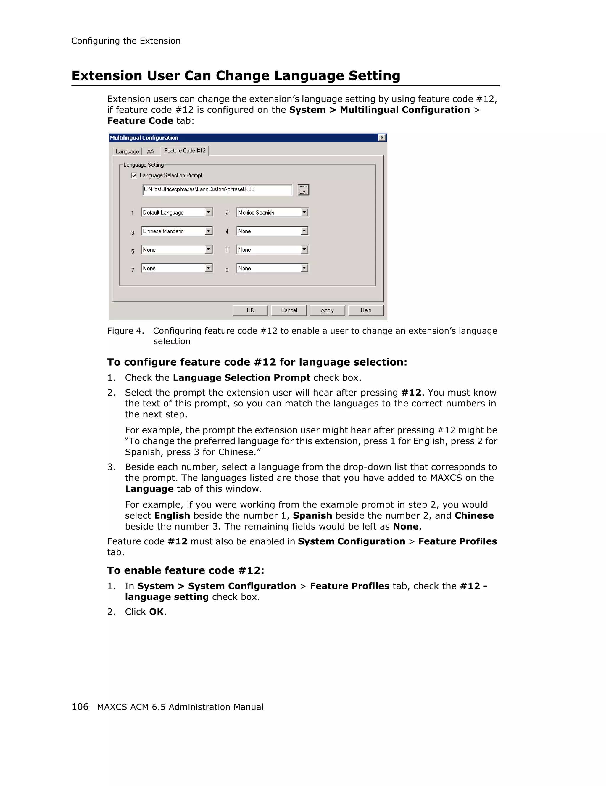
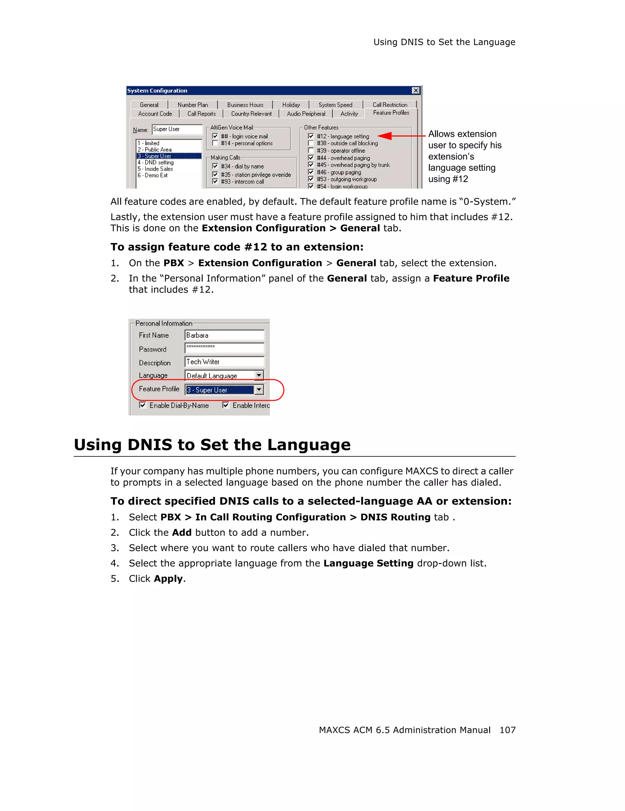
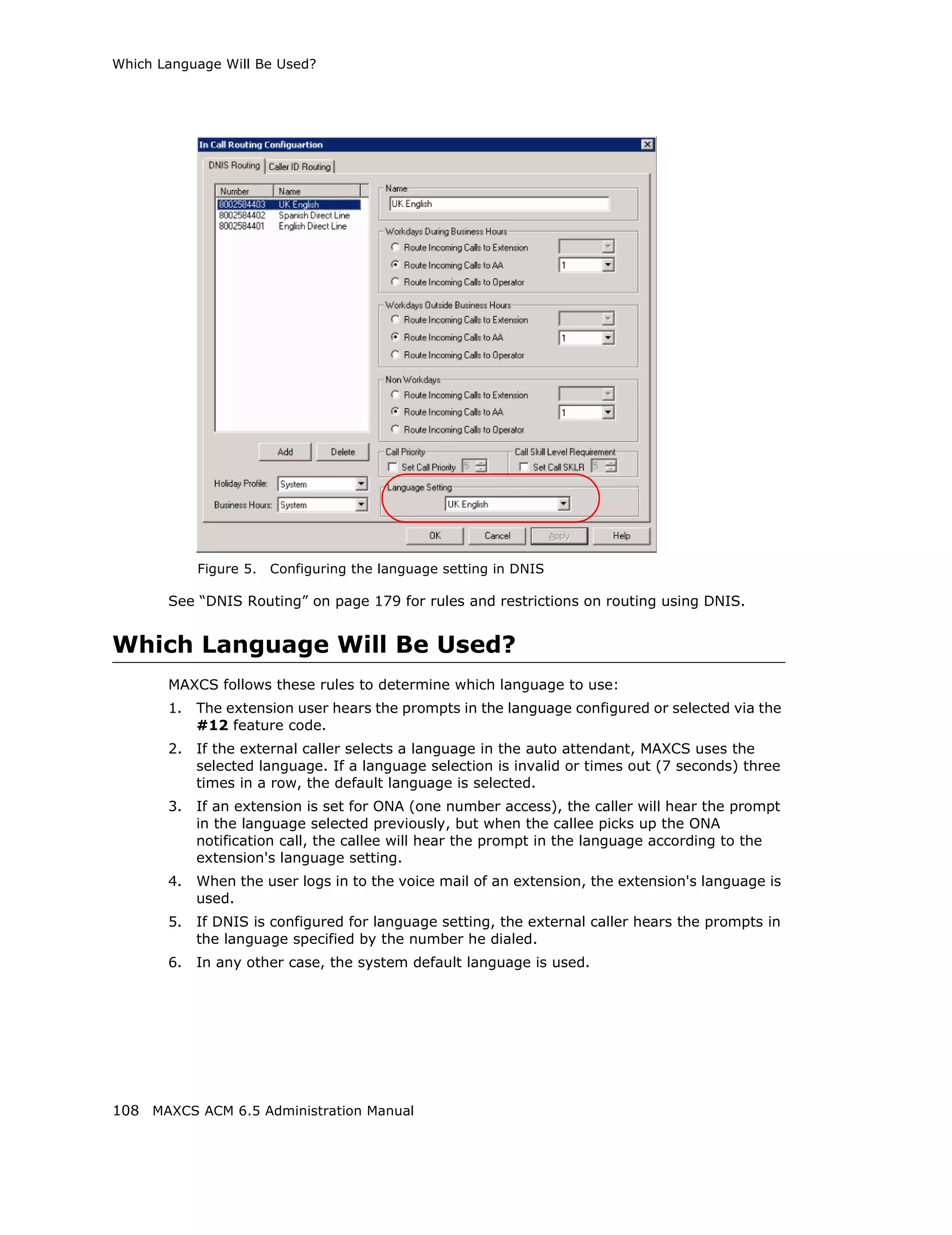
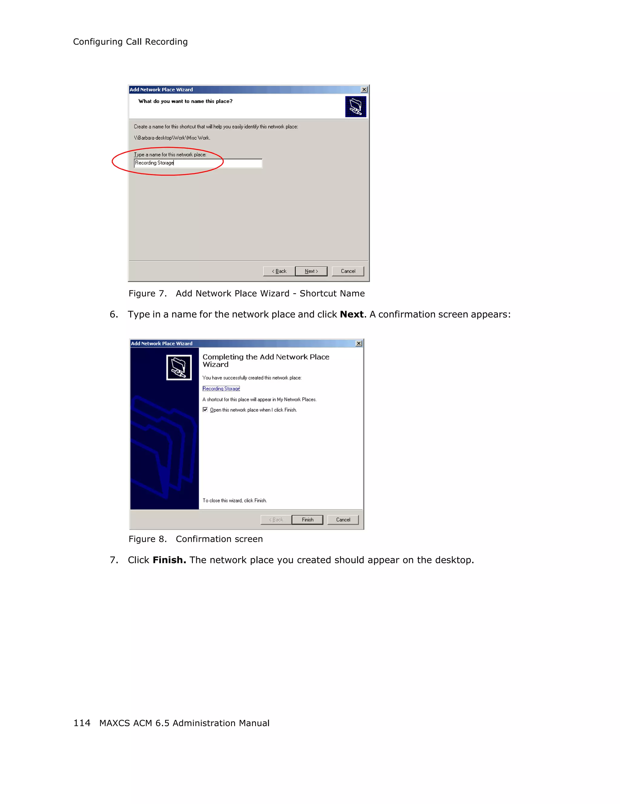
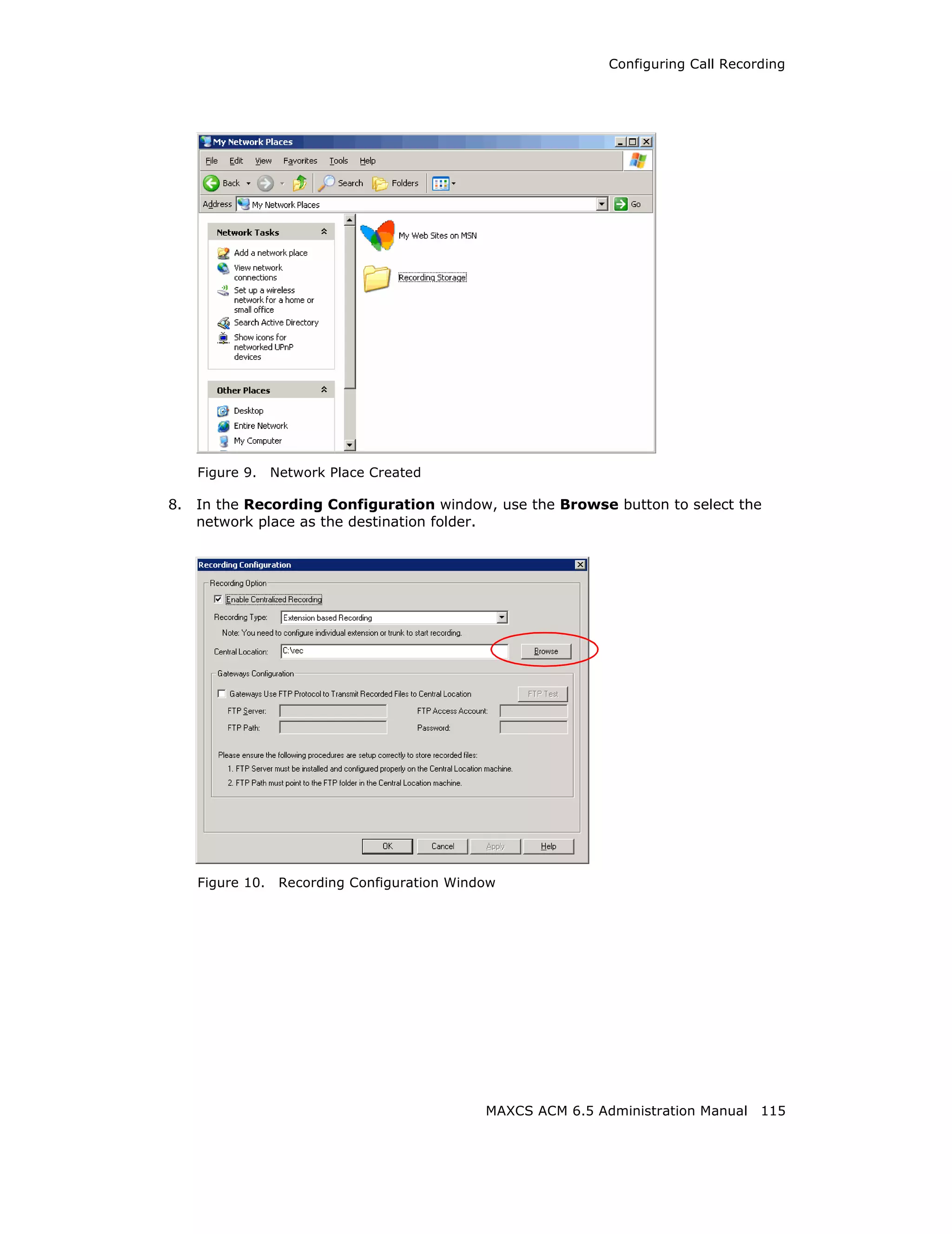
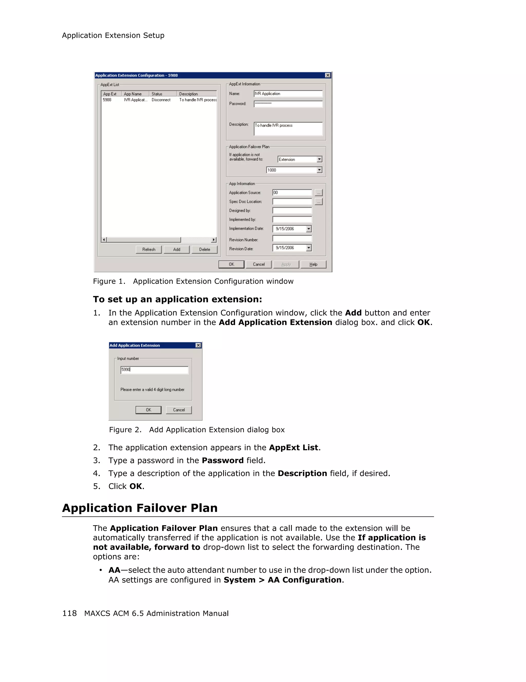
Download to read offline


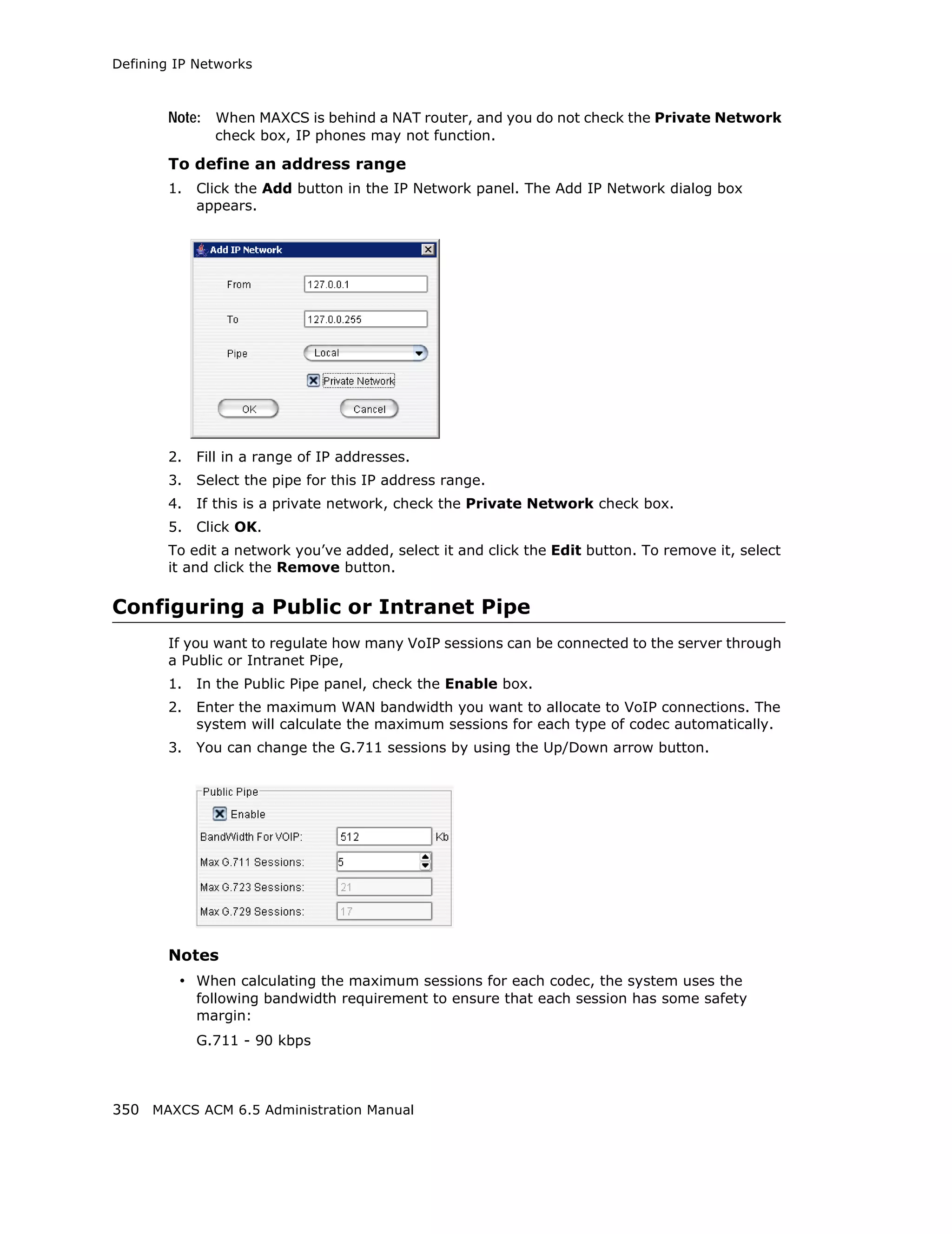
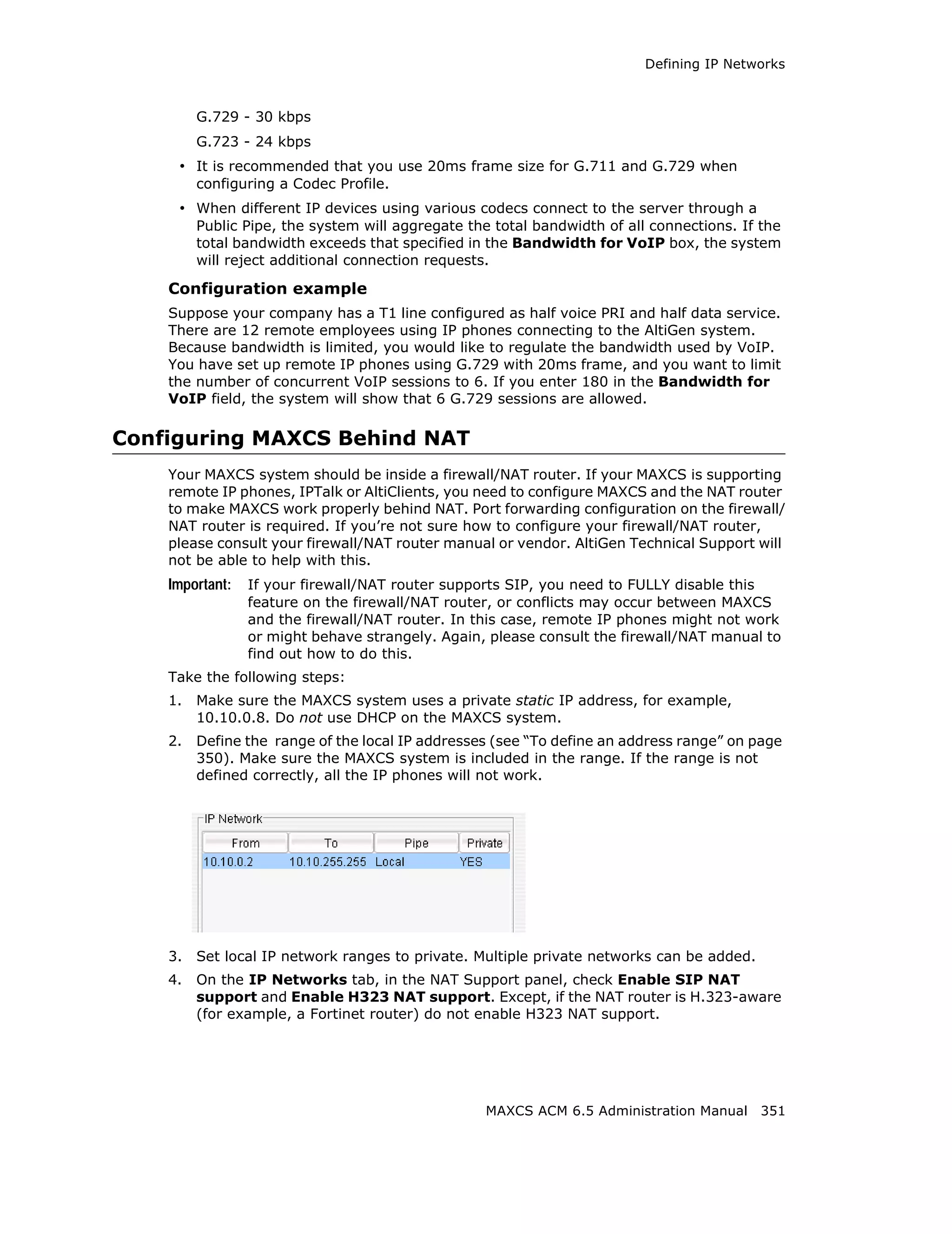
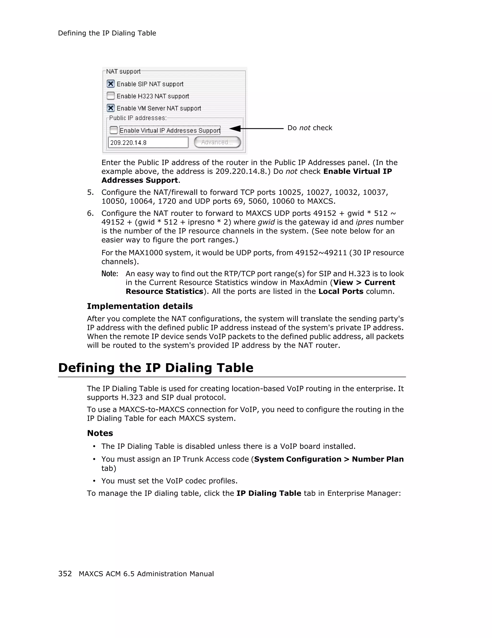
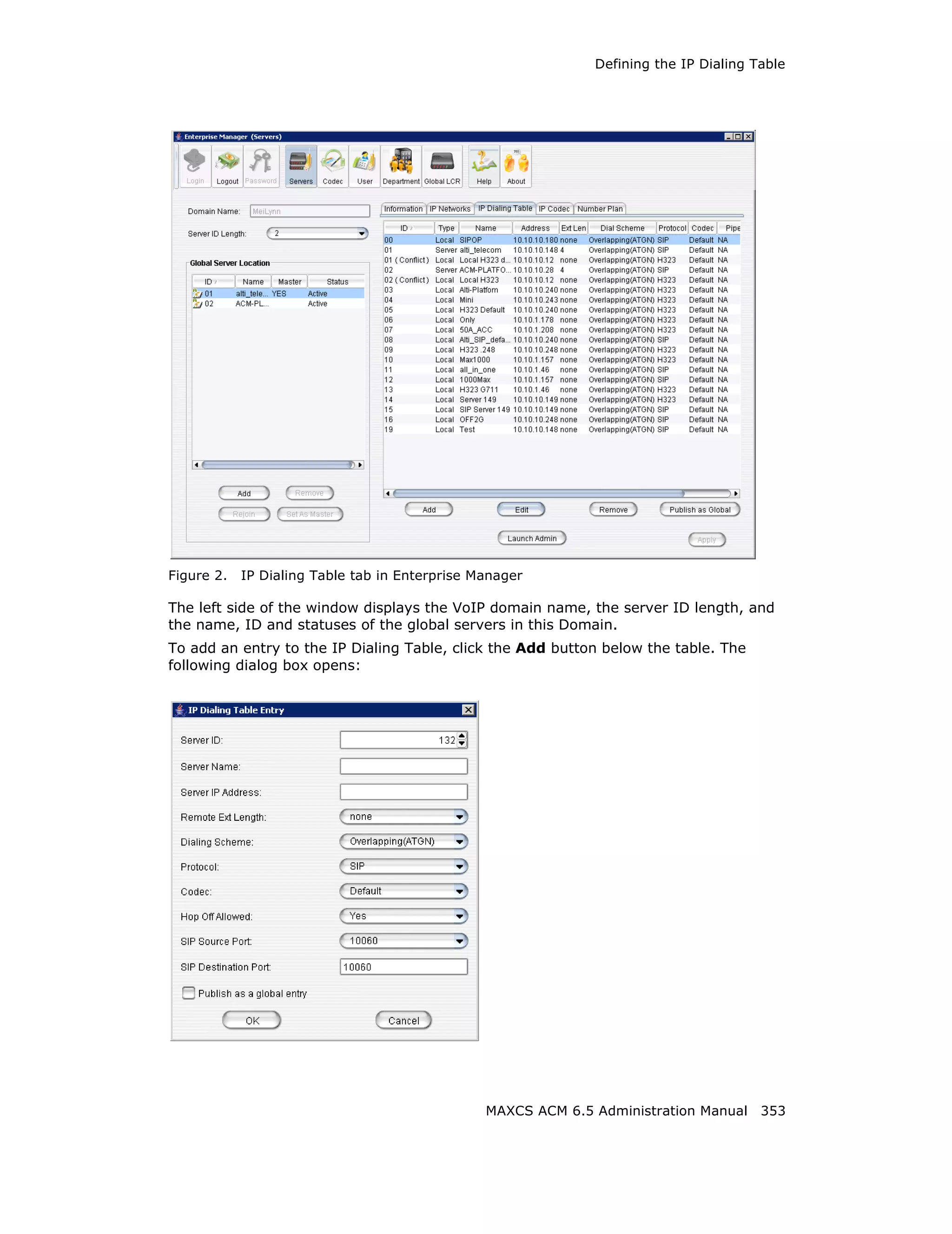
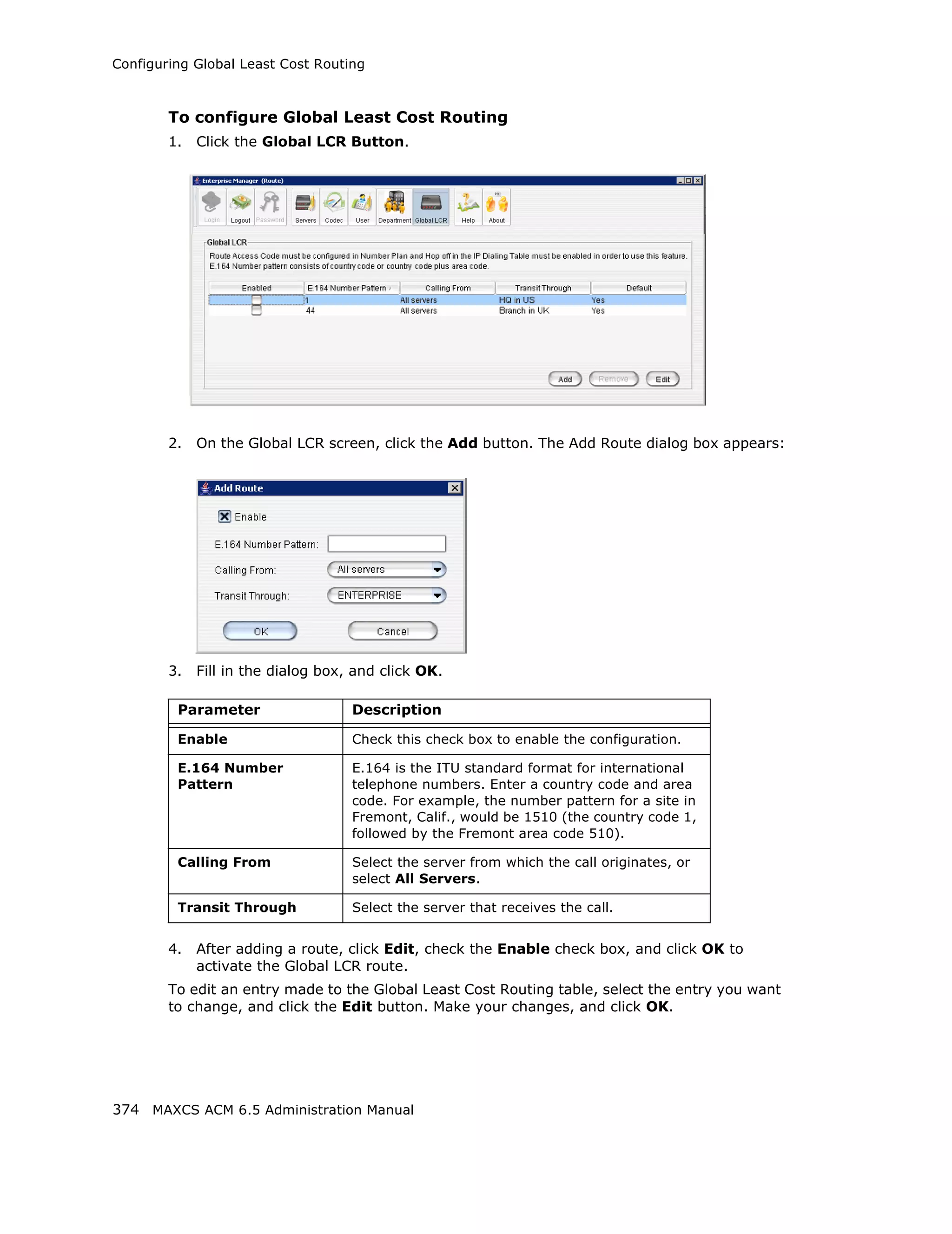
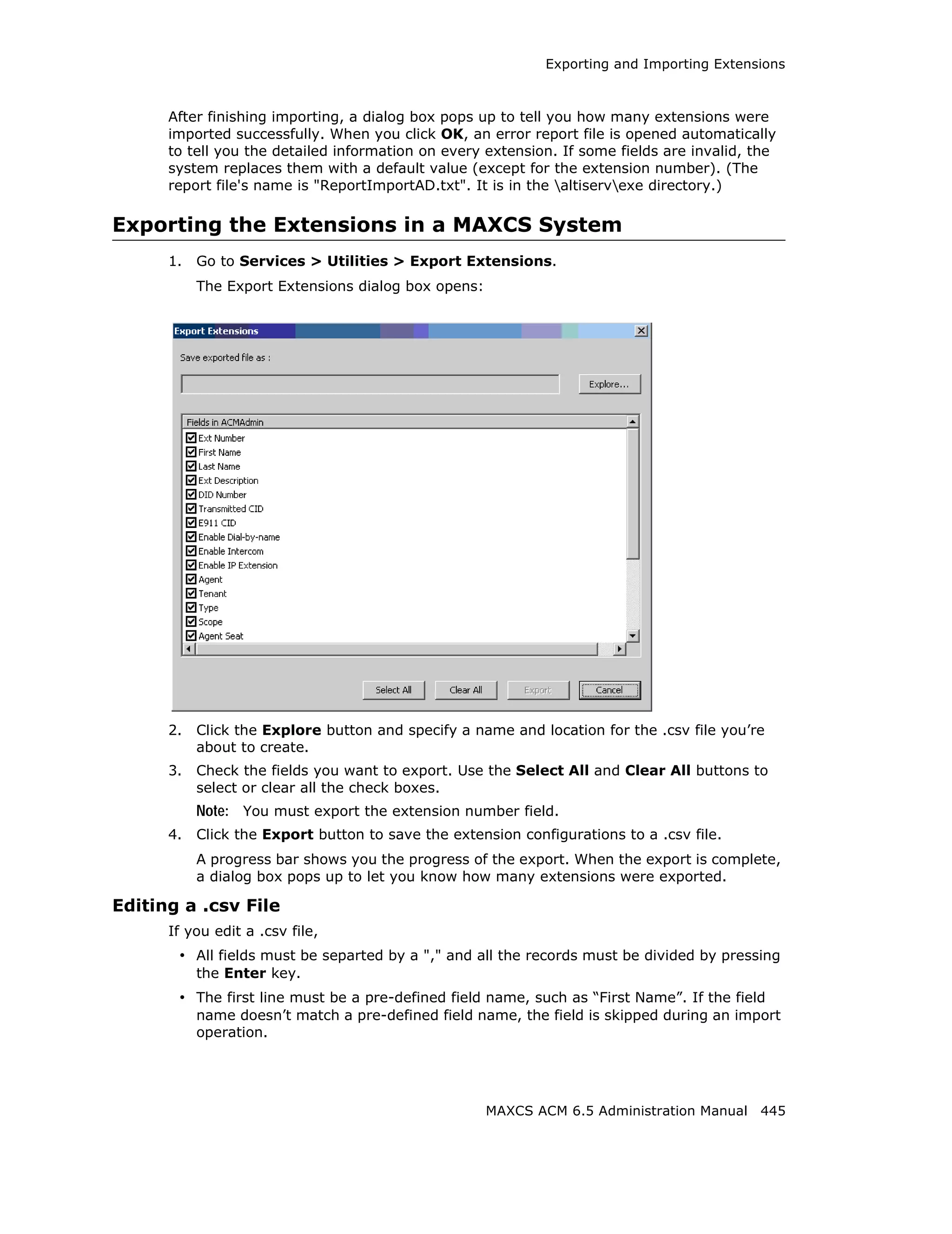
![Audio Peripheral Configuration
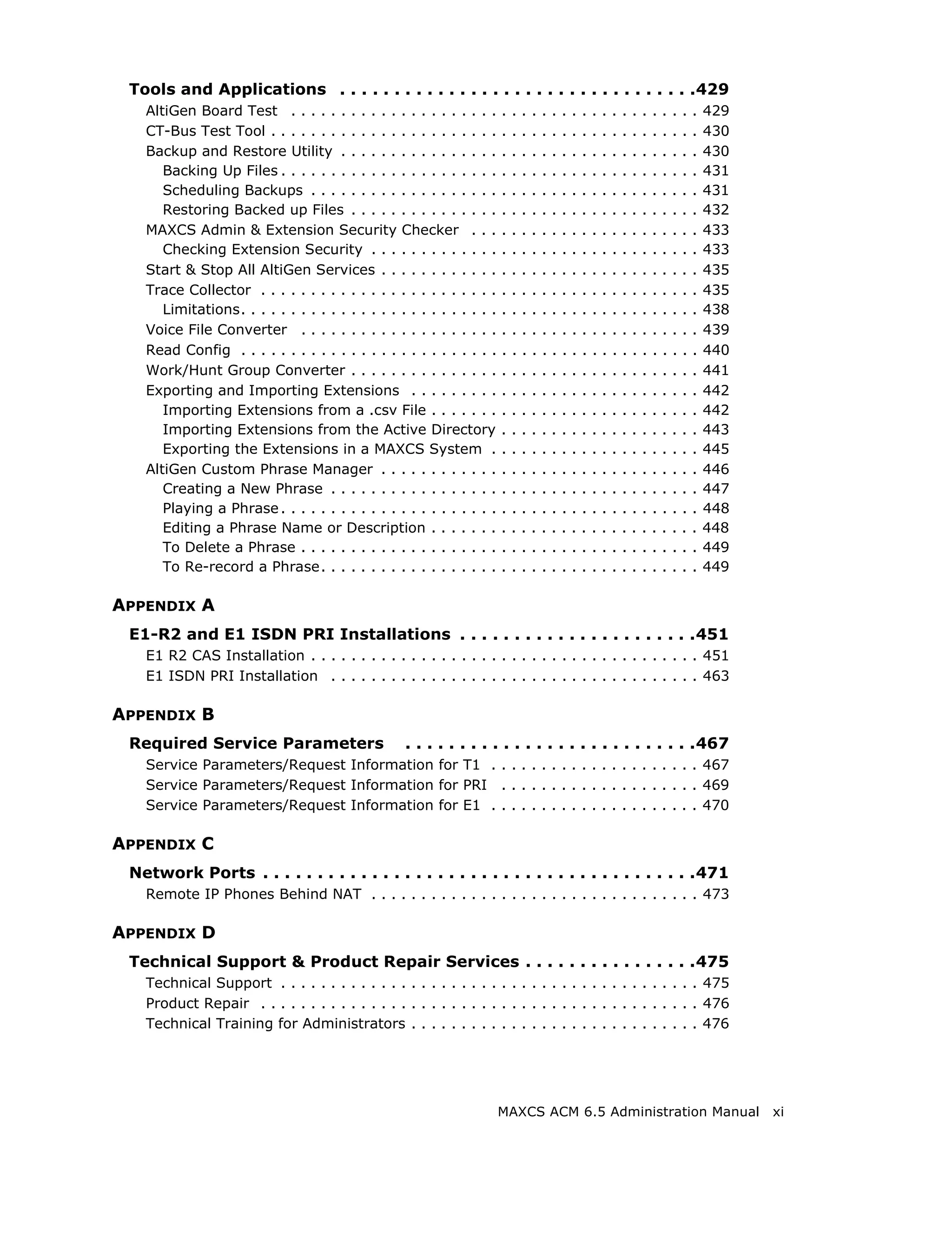
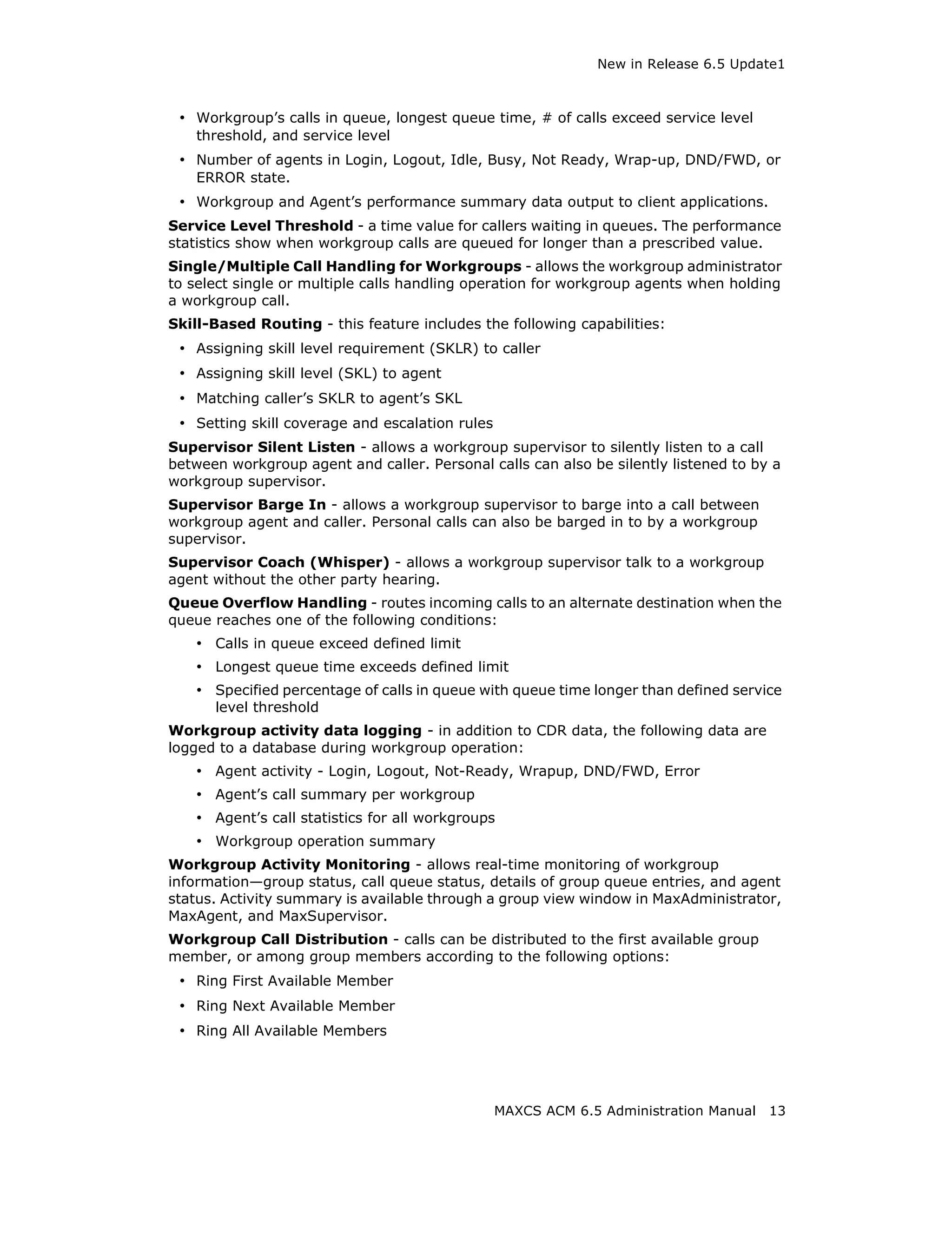
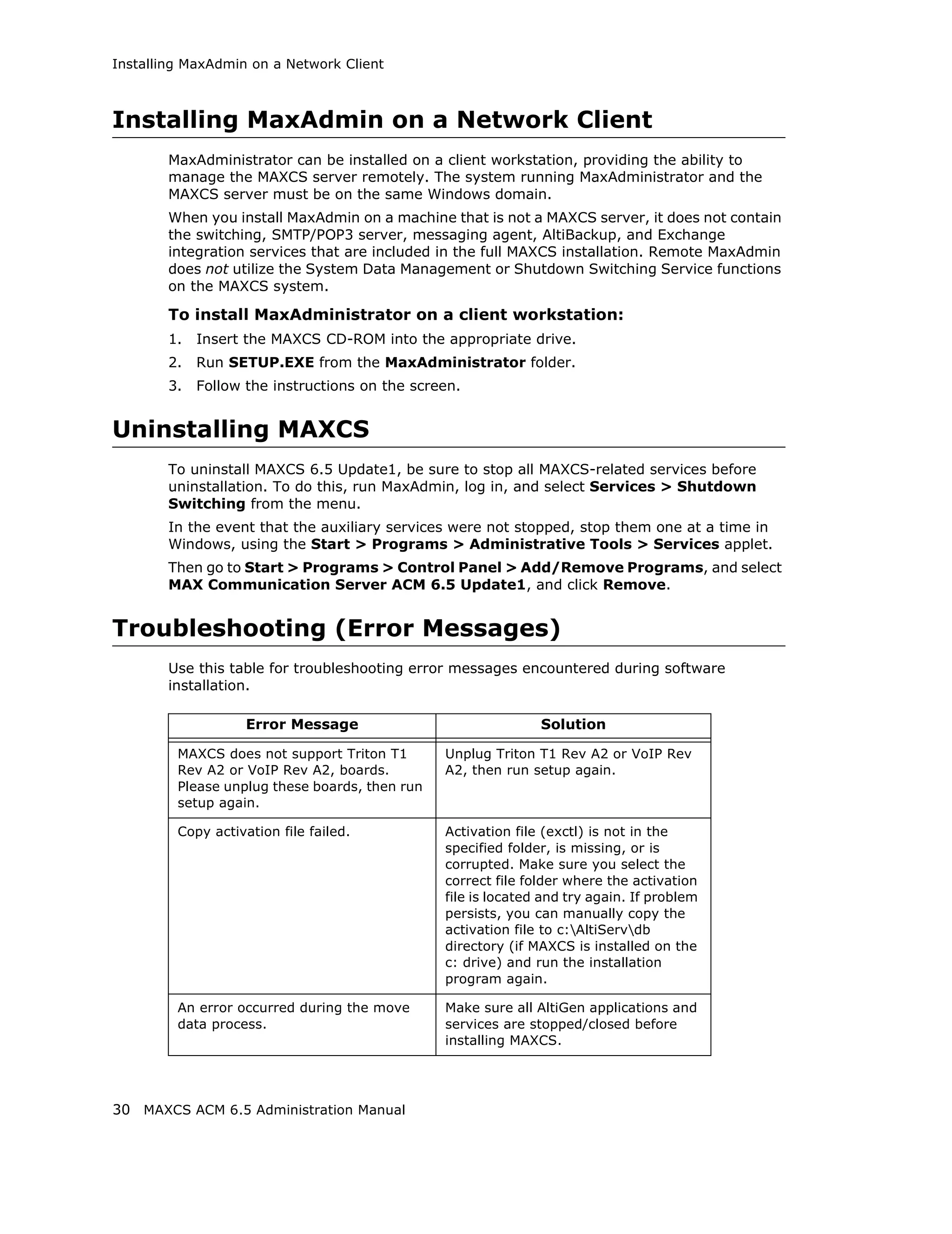
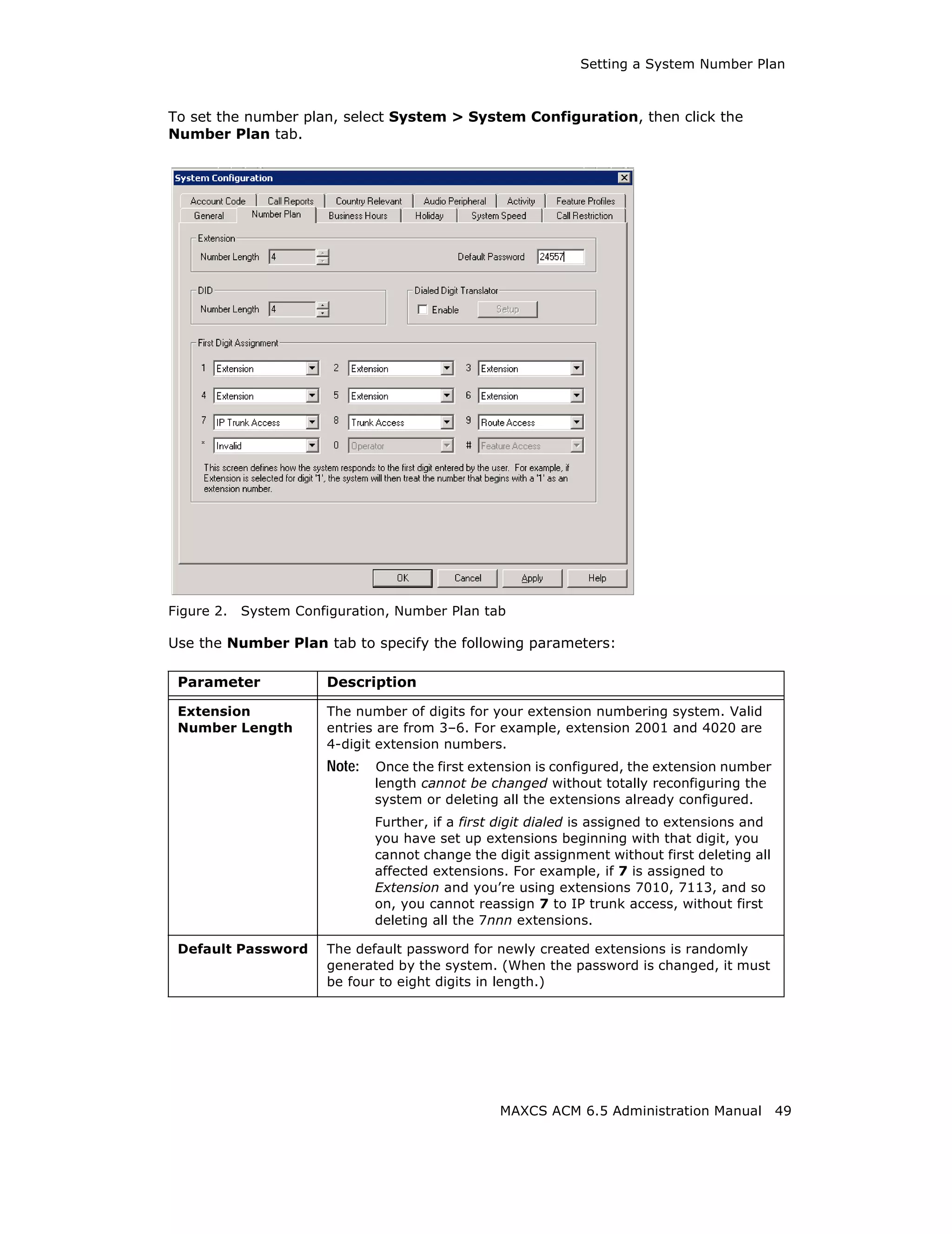
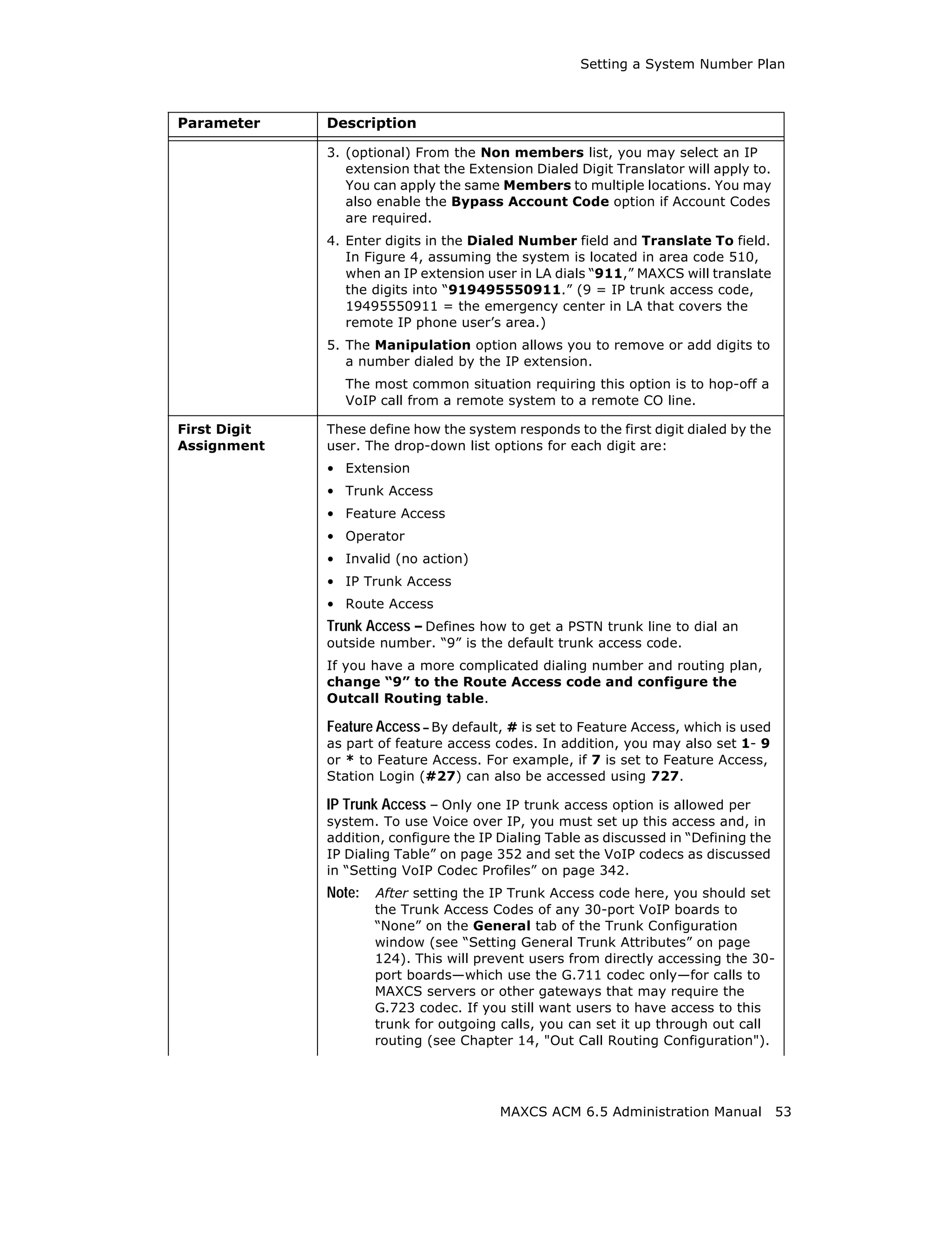
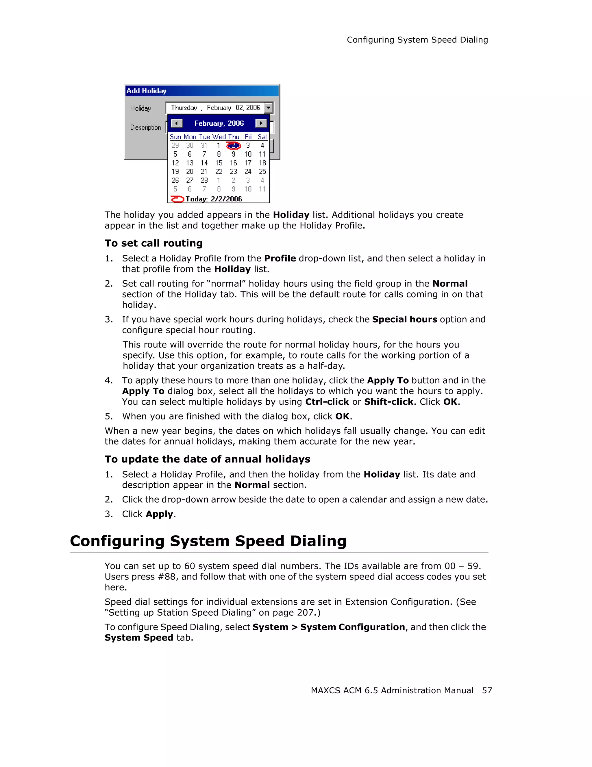
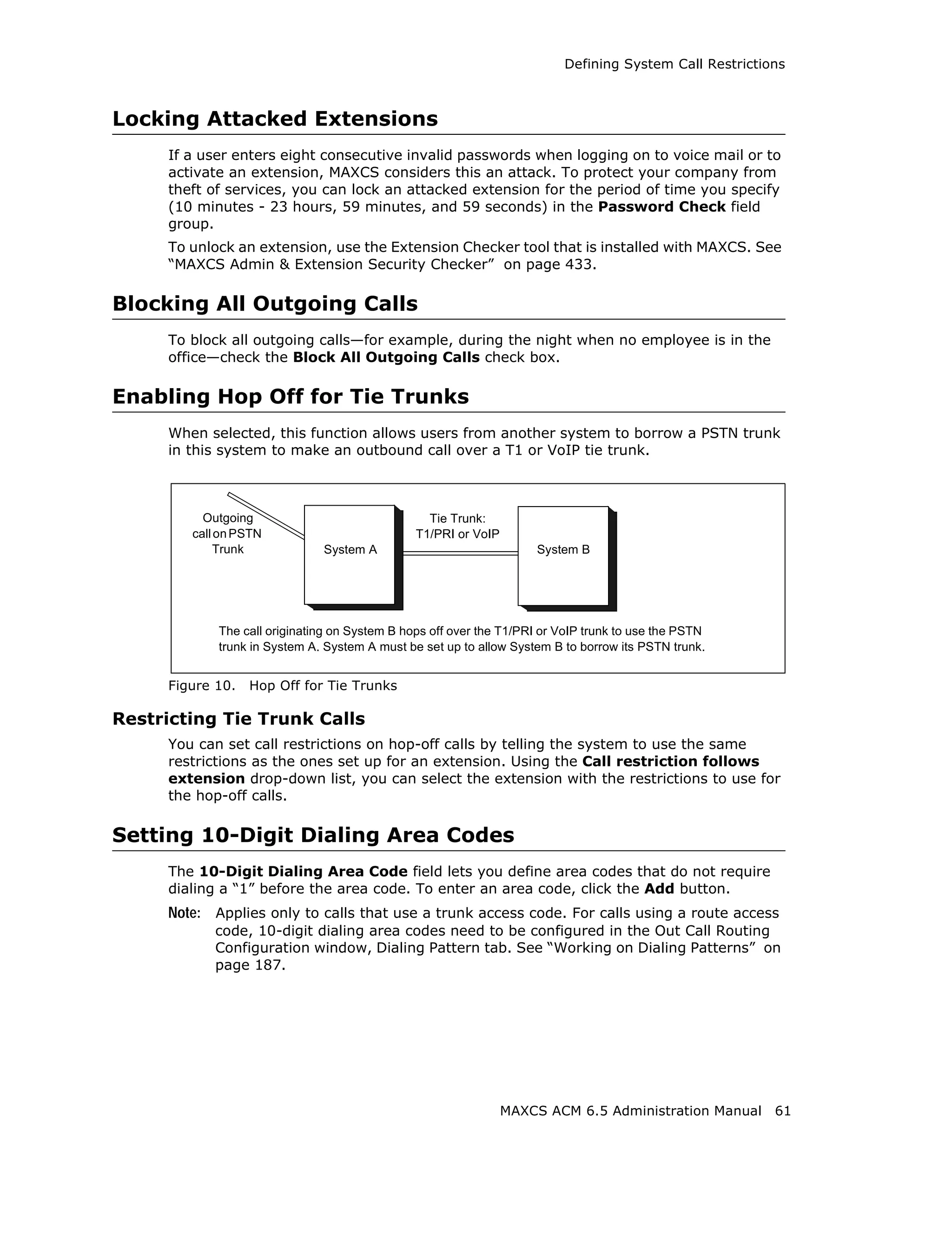
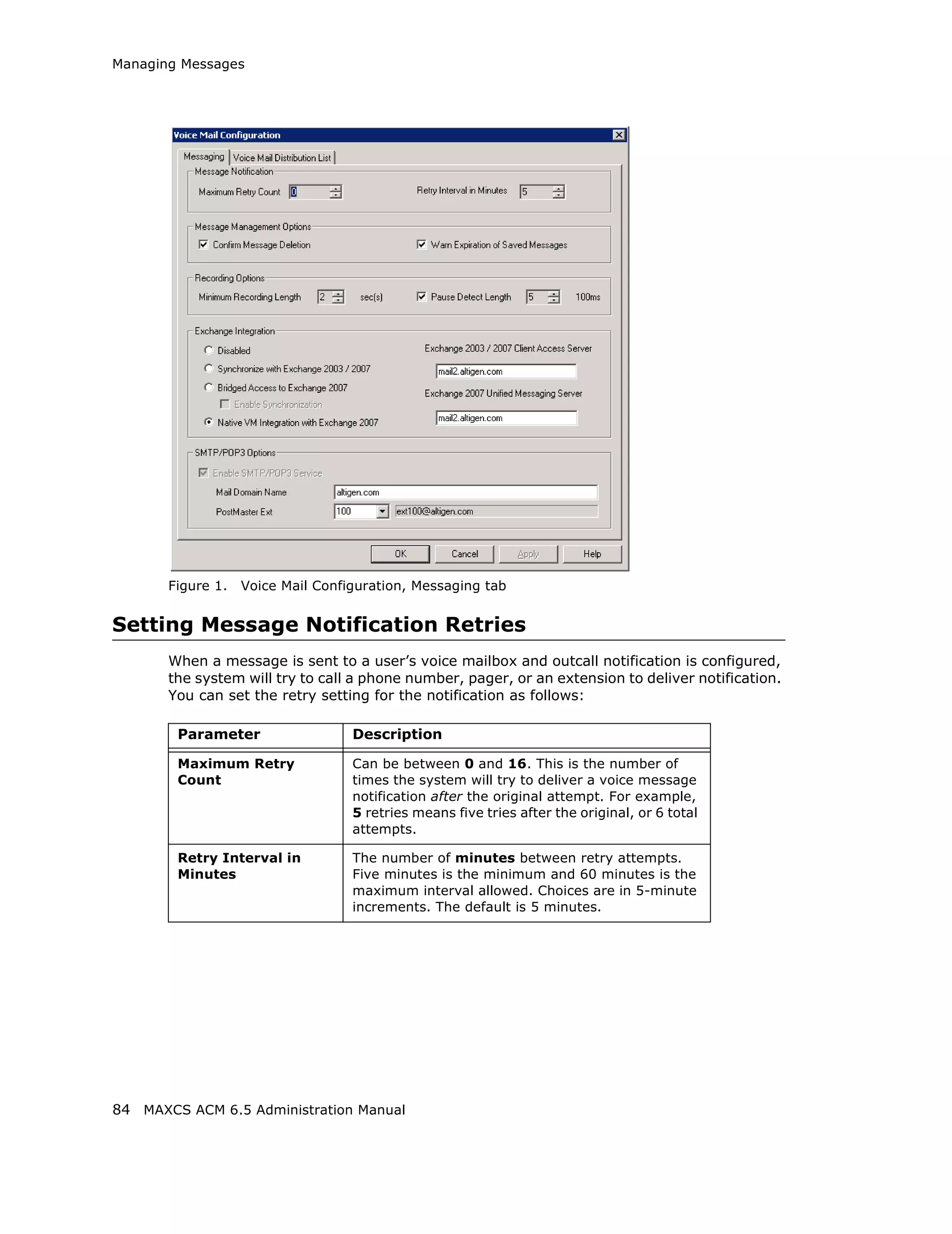
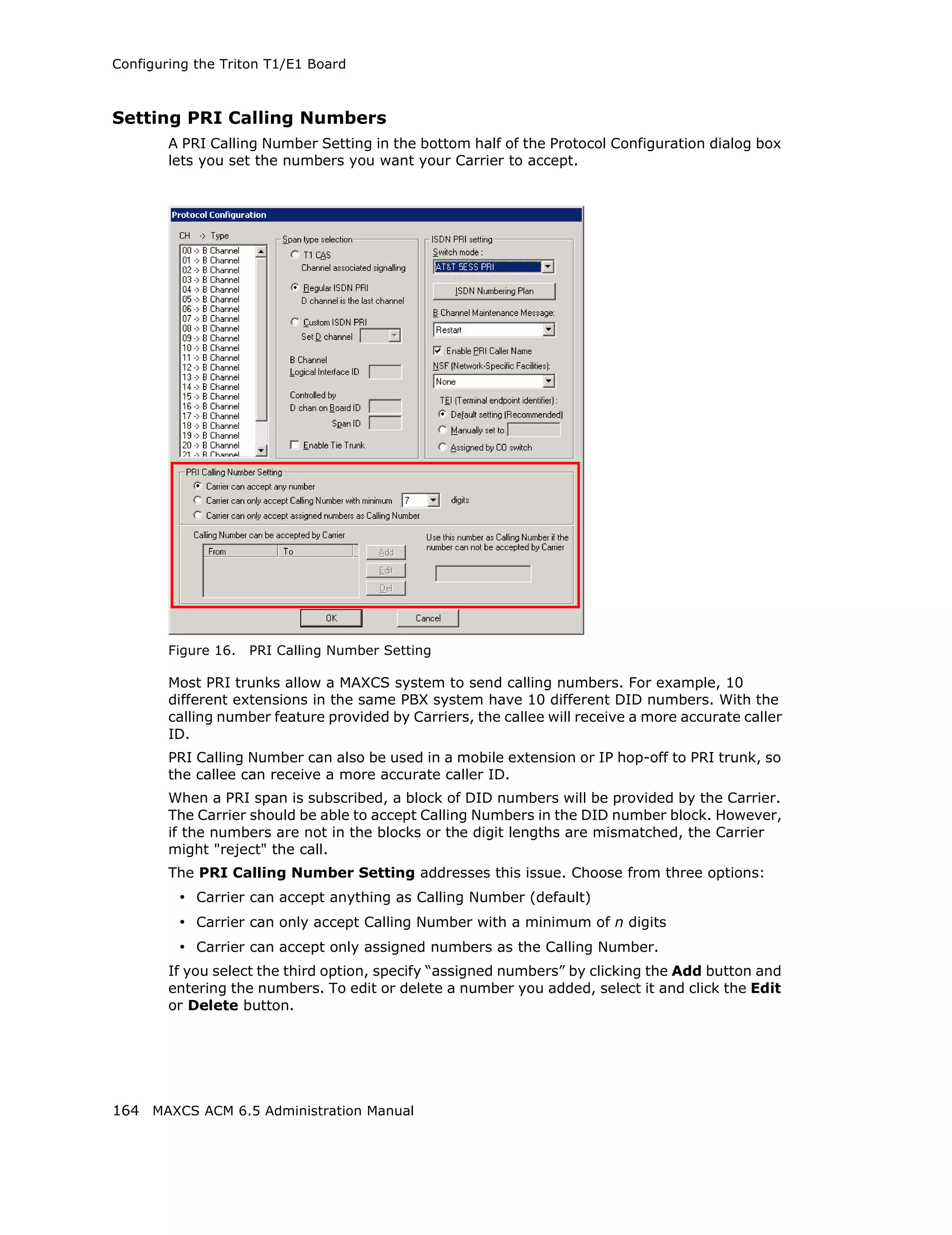
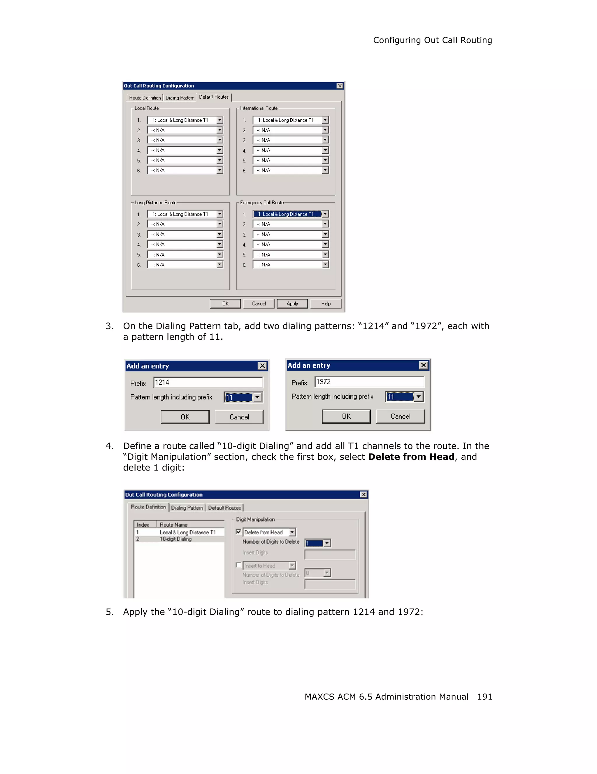
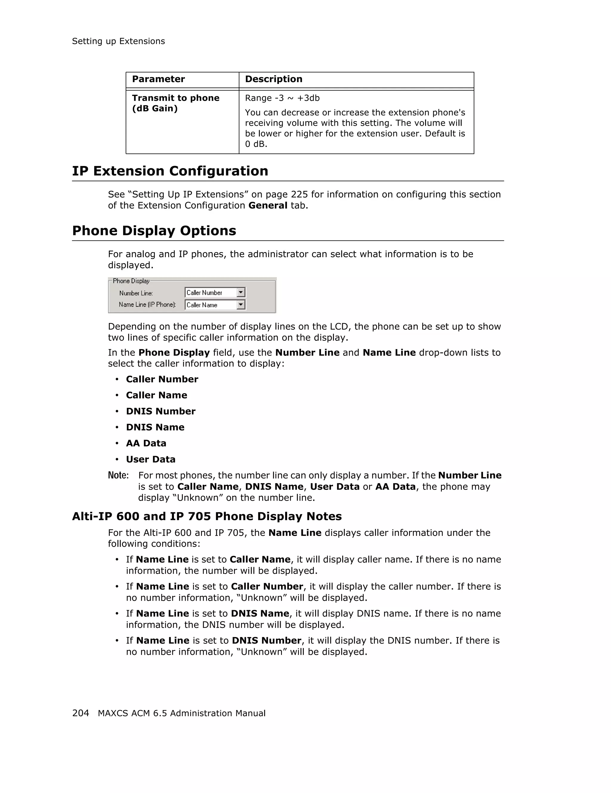
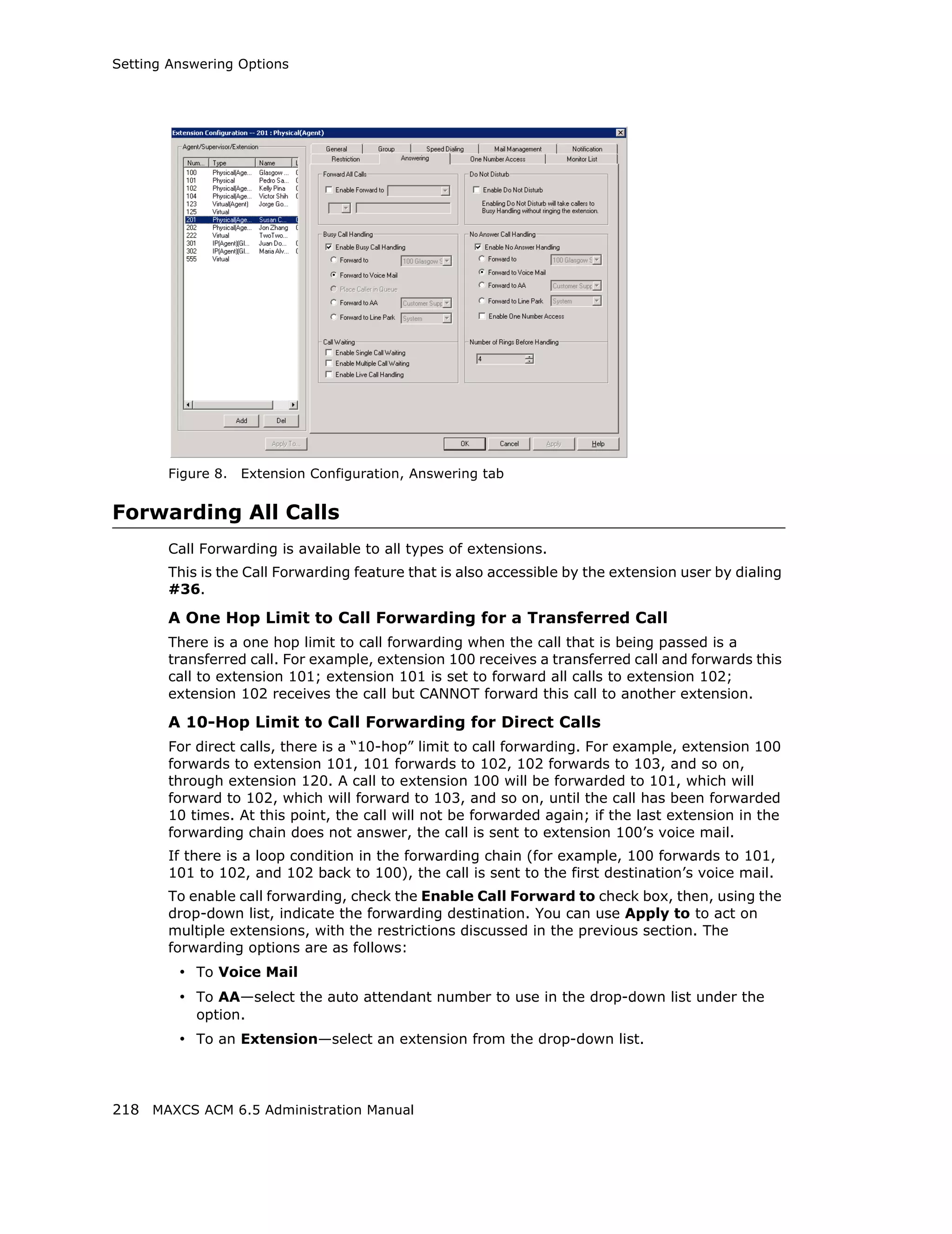
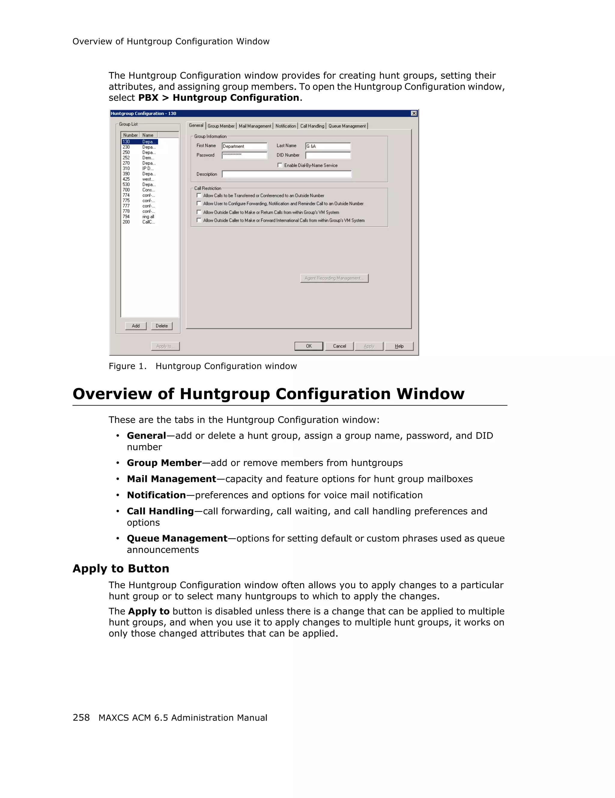
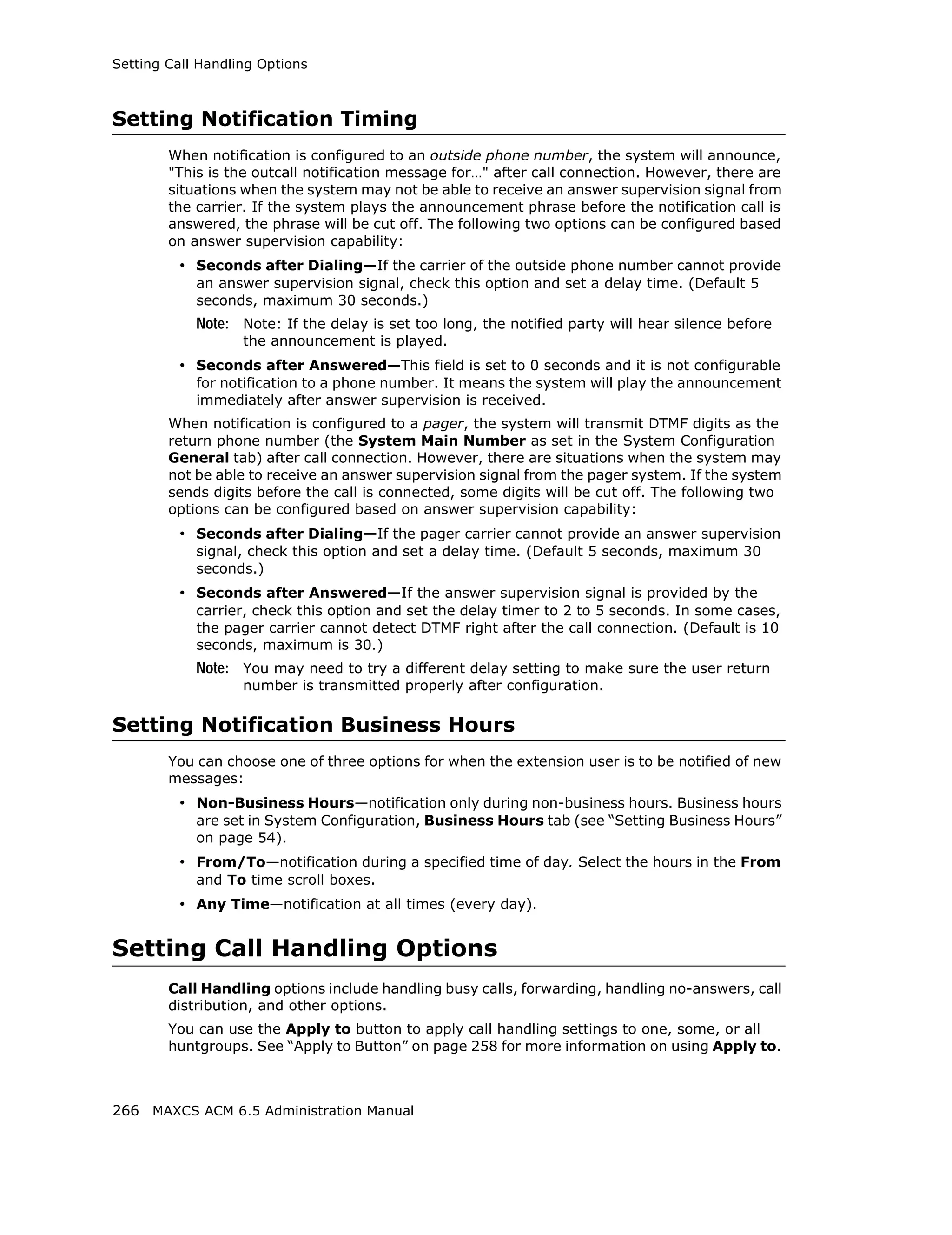
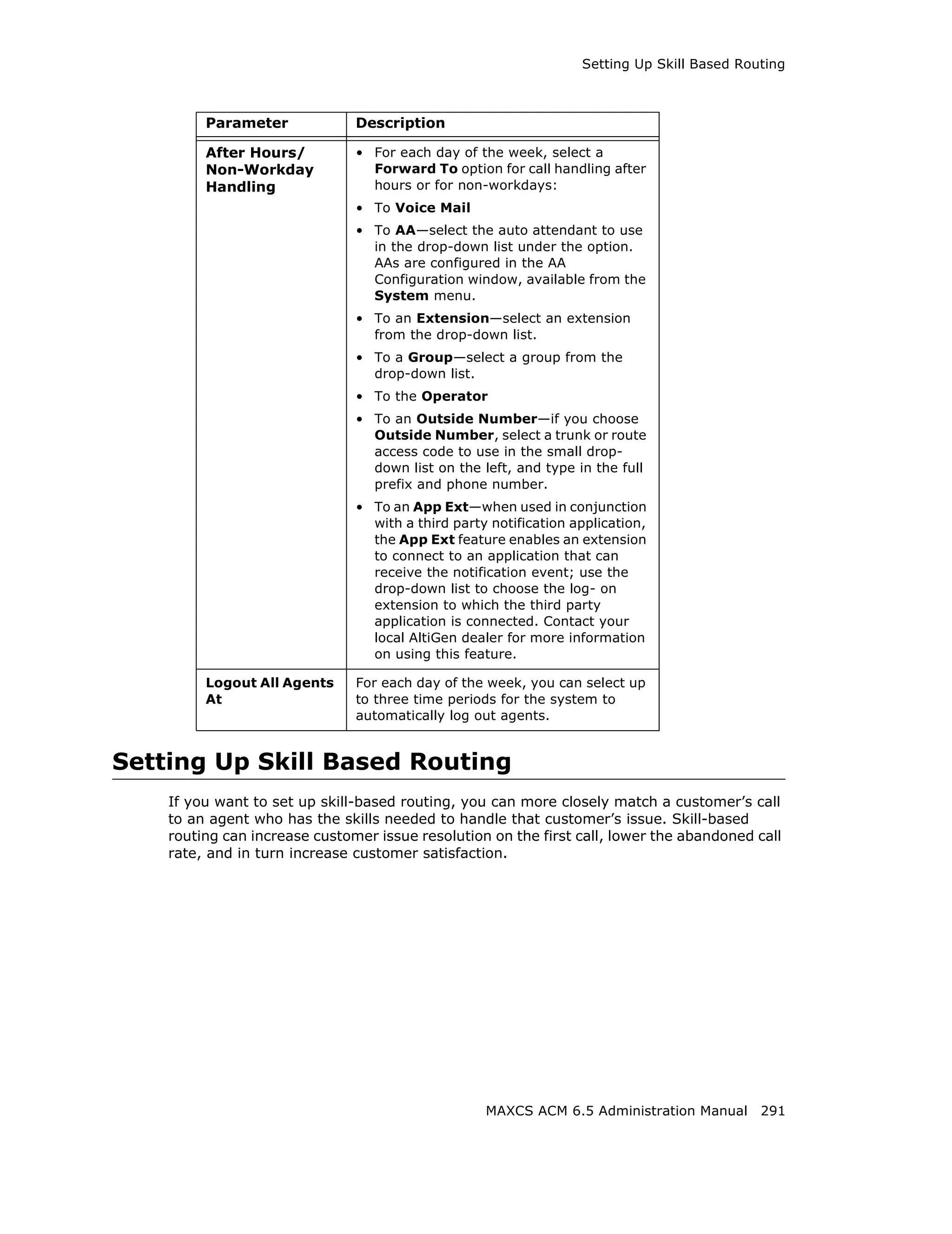
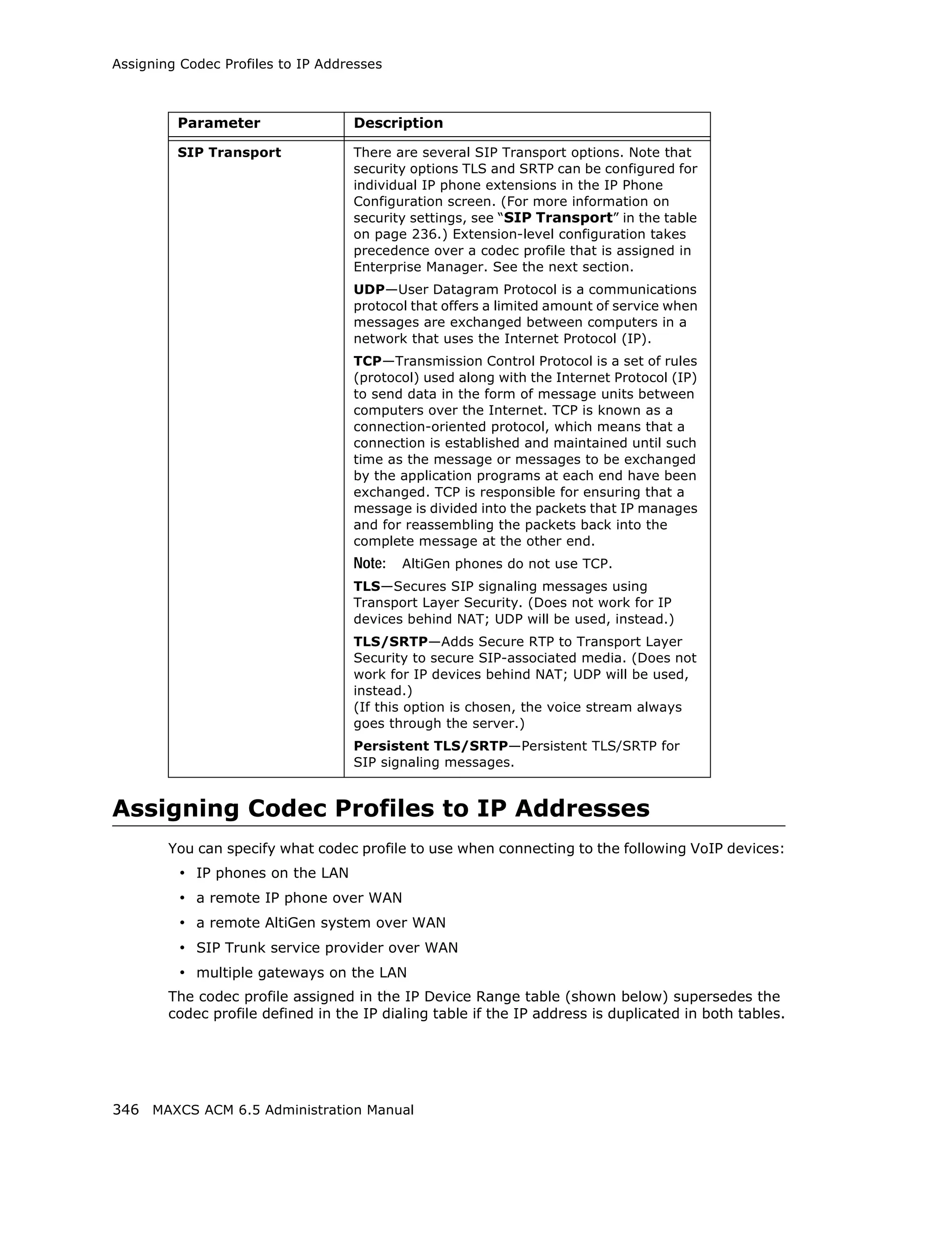
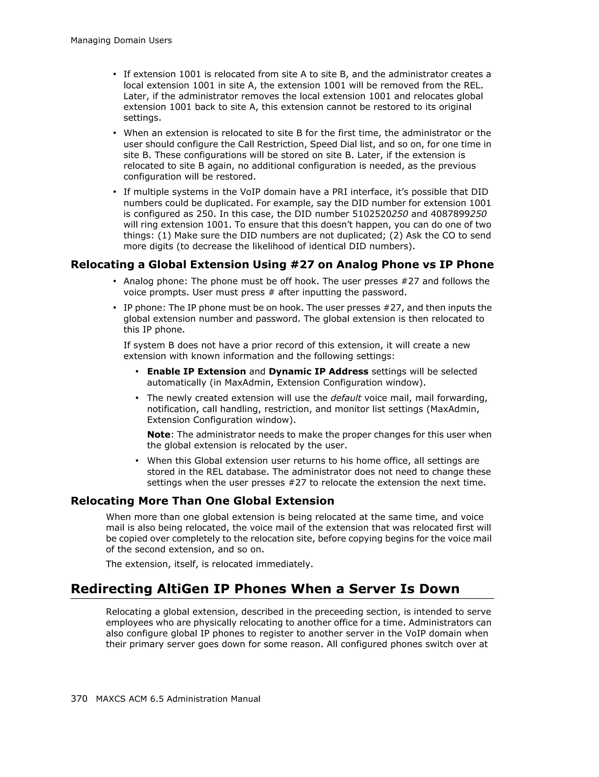
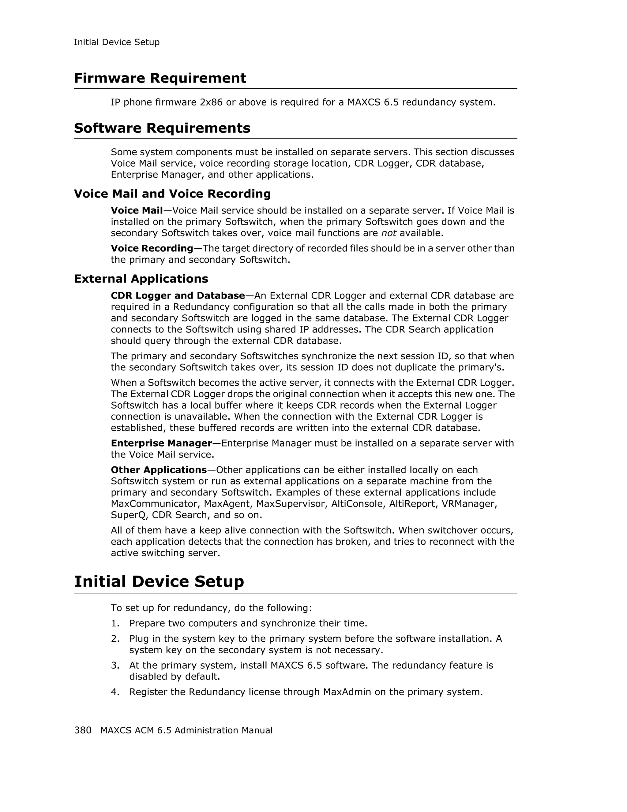
Setting Emergency Numbers
The number in the Emergency Number field will have the system automatically find a
trunk to process the call without the extension user dialing a trunk access code first. You
may enter up to three emergency numbers in the appropriate fields.
Note: This feature works with both trunk access code and route access code.
Dialing Plan Rules for Non-North American Country
If your MAXCS system is in a country other than the U.S.A. or Canada, you can configure
a call return rule based on the country, which will greatly improve the call return feature
from Caller ID, Zoomerang, and making a call from Microsoft Outlook.
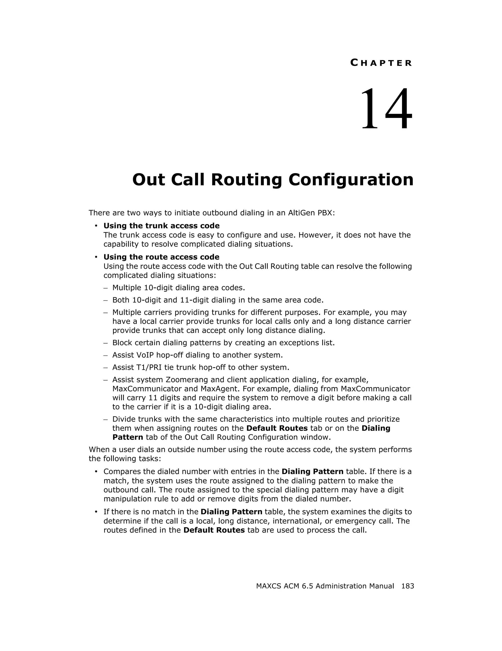
Click the Automatic Dialing Plan Rules button. The following dialog box appears:
Figure 15. Automatic Dialing Plan Rules dialog box
Define the Local Plan, Domestic Plan, and International Plan. A character of the pattern
can be a digit from 0 to 9. It can also be a range of digits, for example, [0-3]. If it is a
question mark, '?', it is equivalent to [0-9].
When return calls are made, these rules are followed:
• When the number matches Local Plan, the system will send the number out to the
trunk directly.
• When the number matches the Domestic Plan, the system will send the number out
with the domestic toll call prefix.
• When the number matches the International Plan, the system will send the number
out with the international toll call prefix.
When a number matches multiple entries, the match with the most digits has priority.
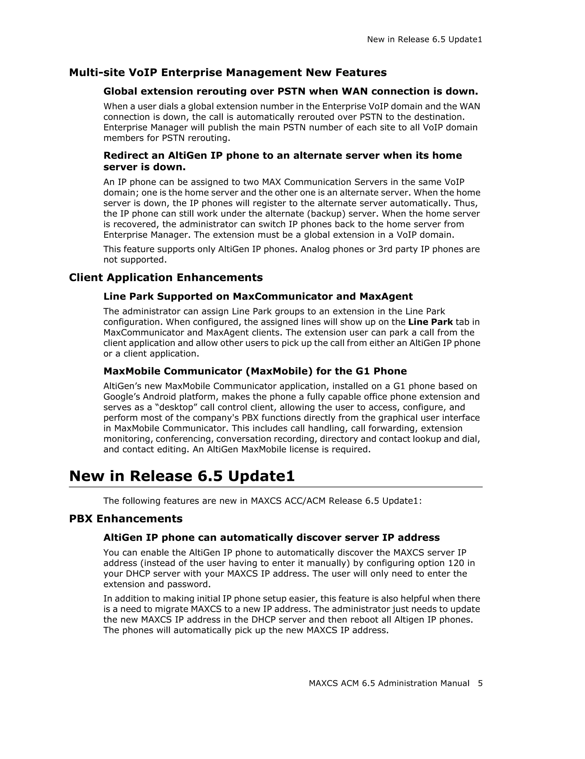
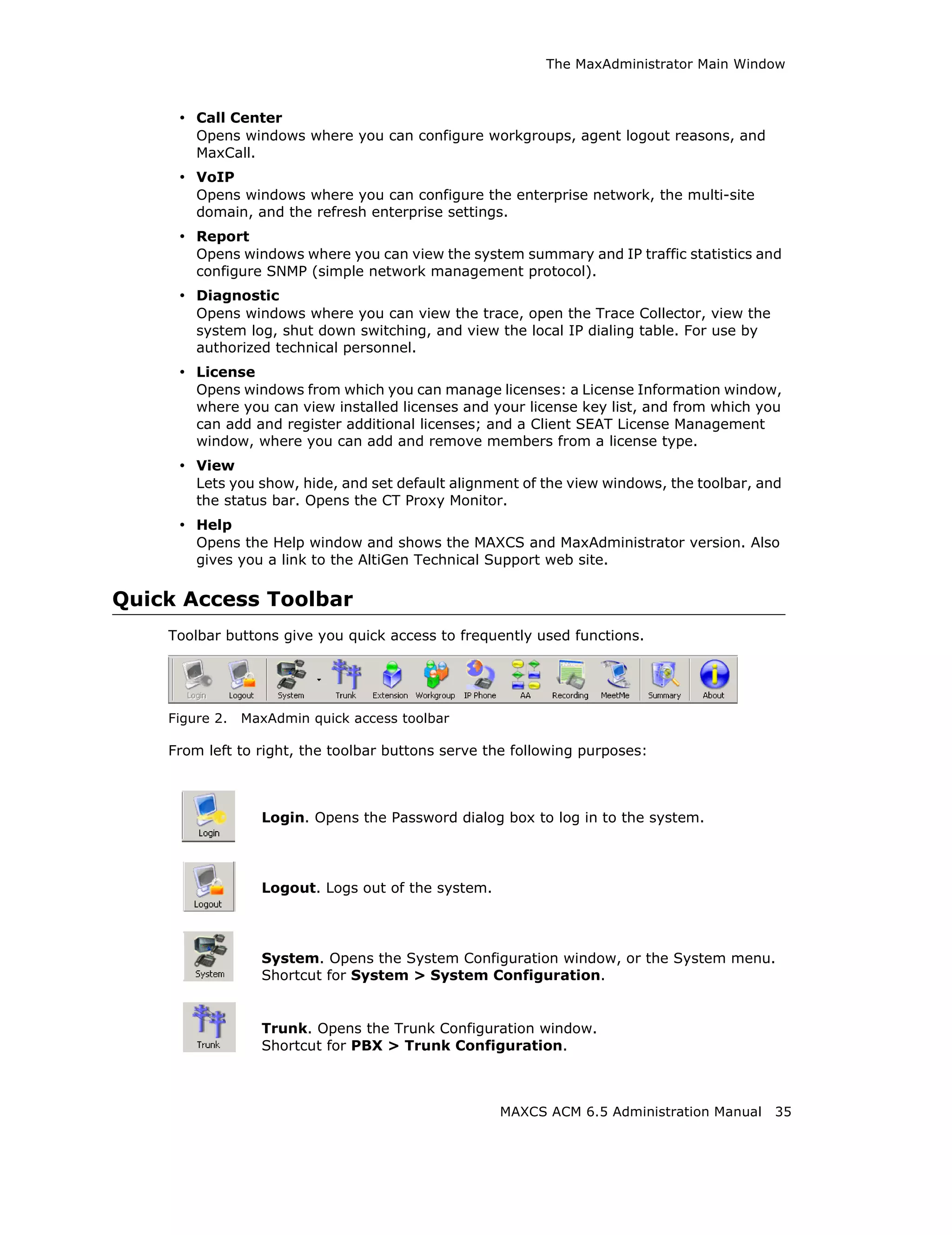
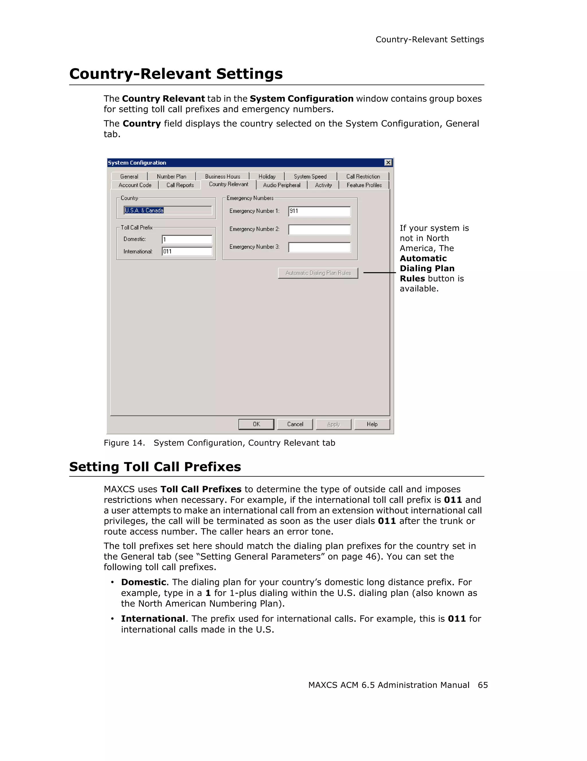
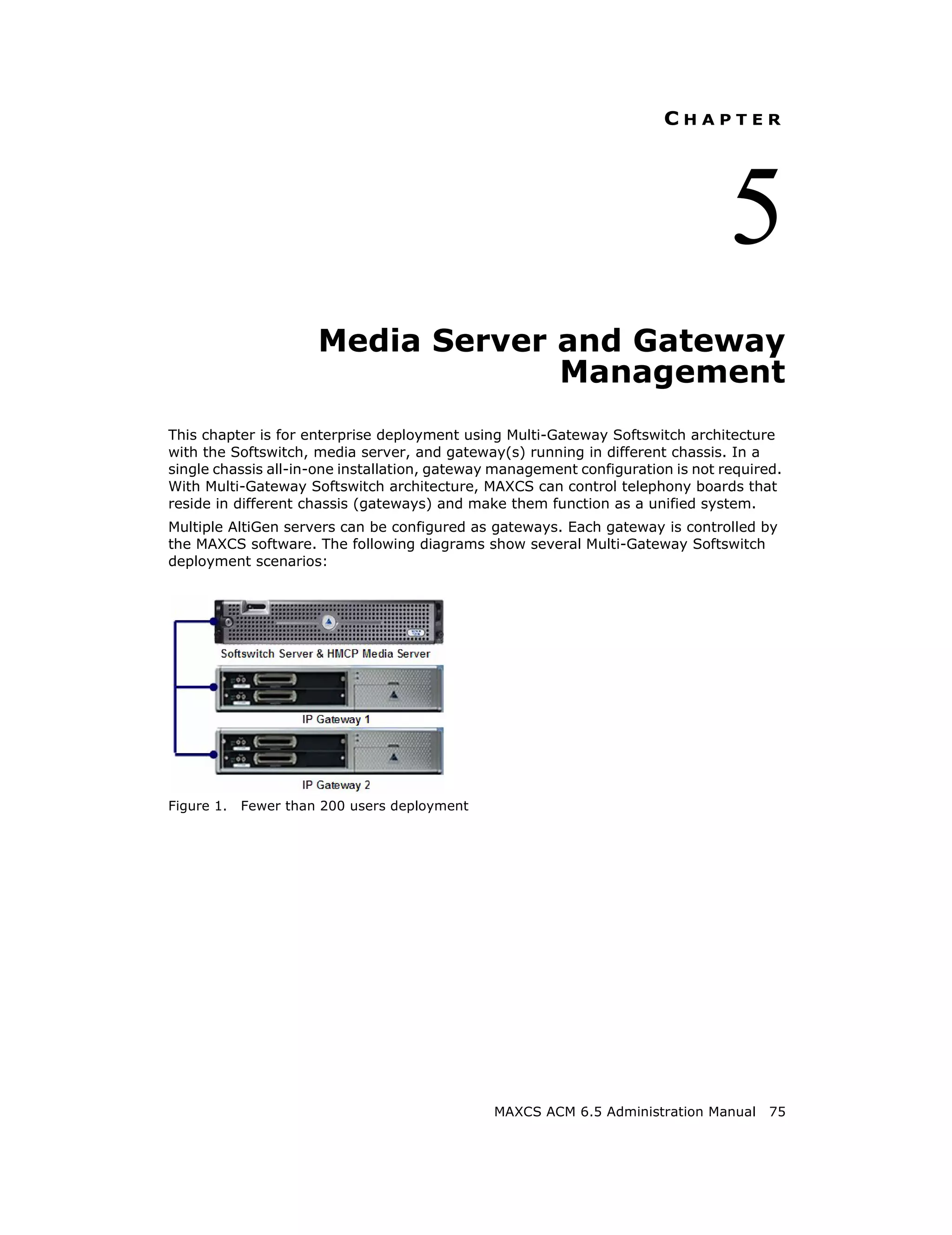
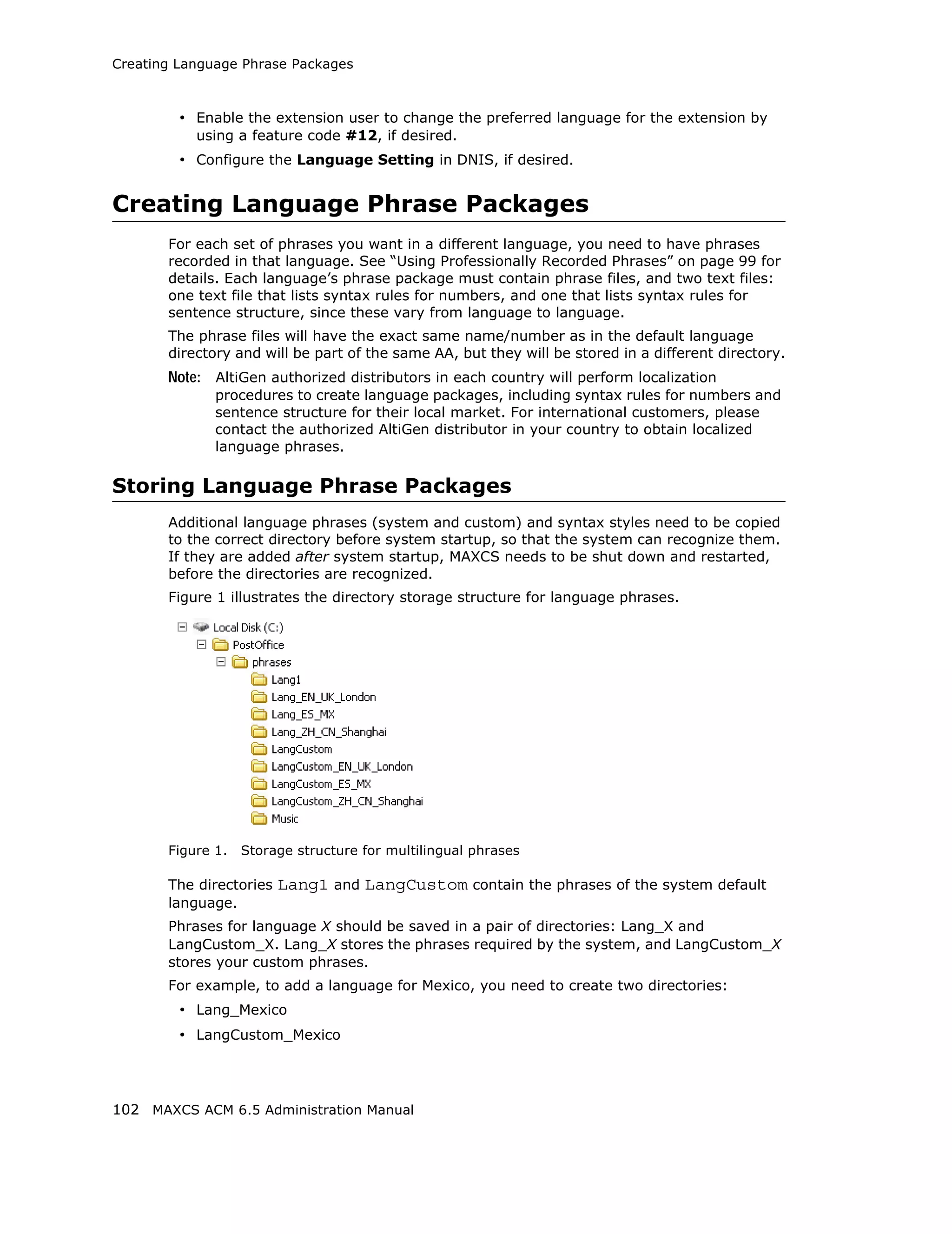
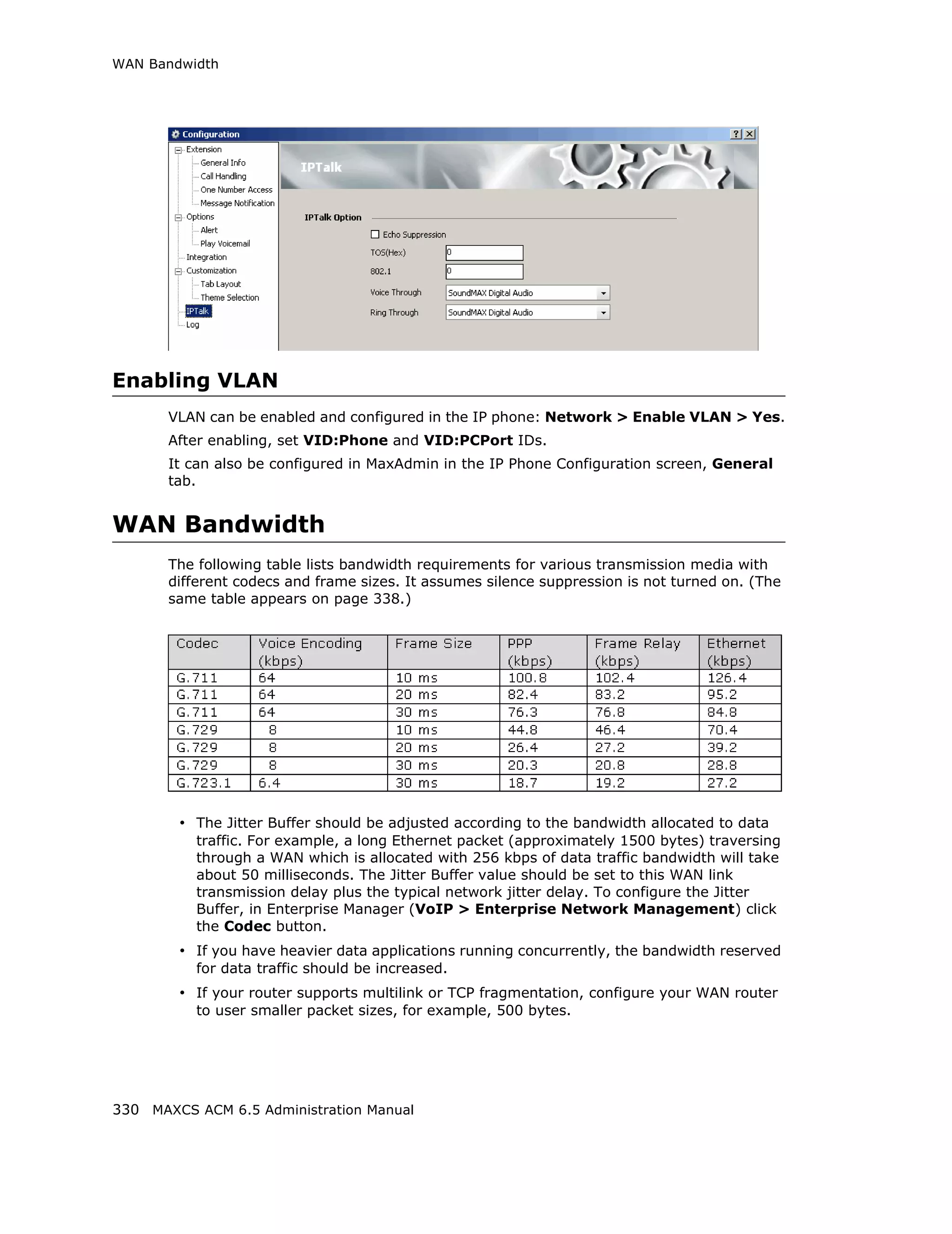
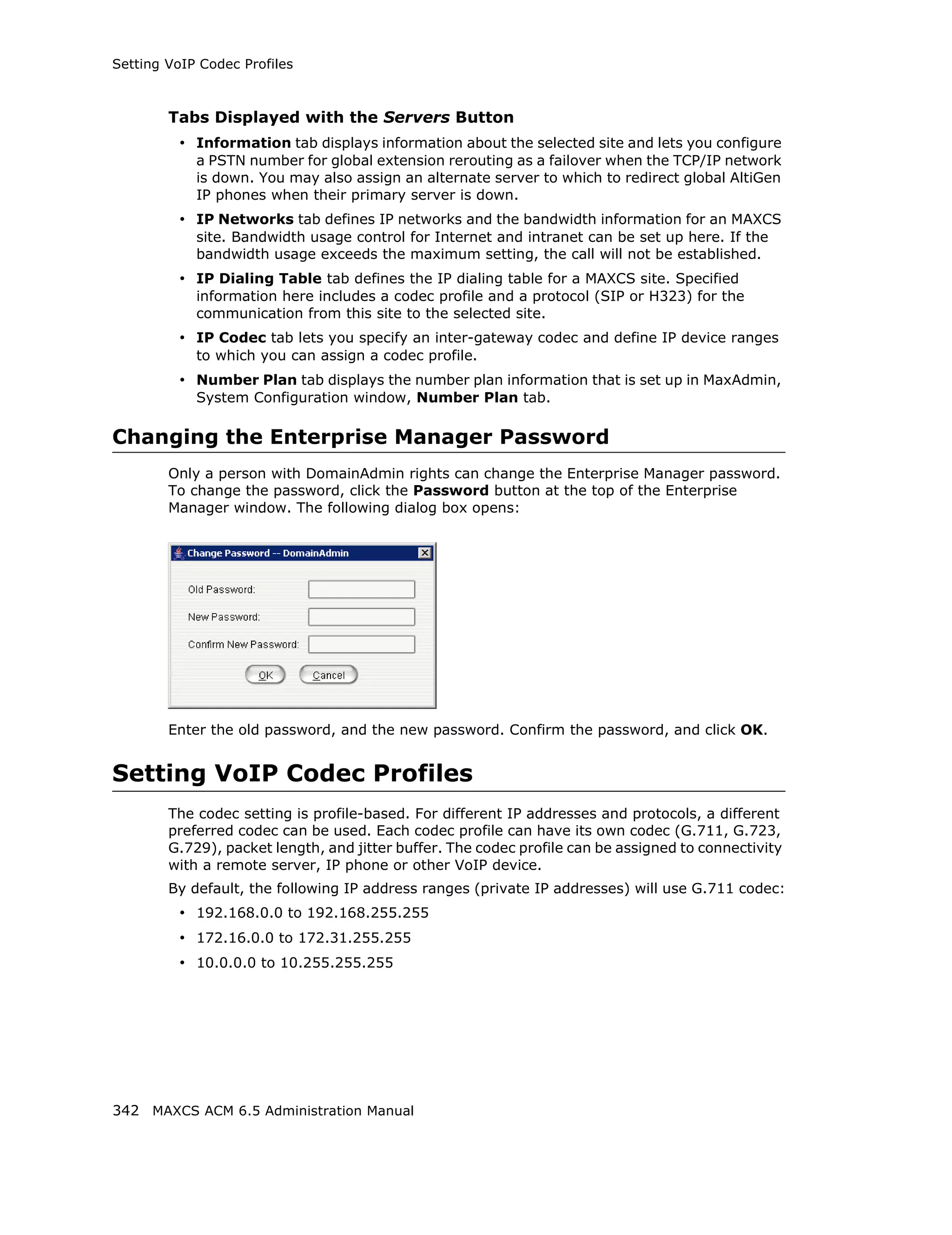
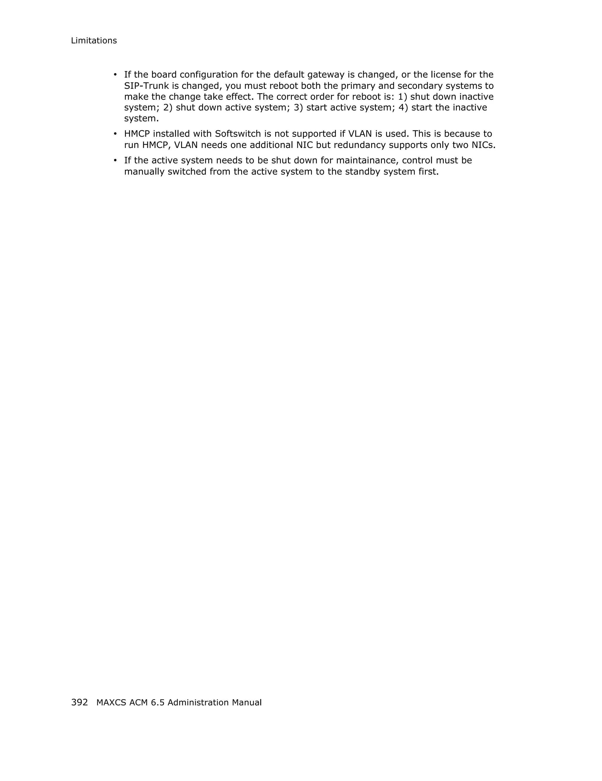
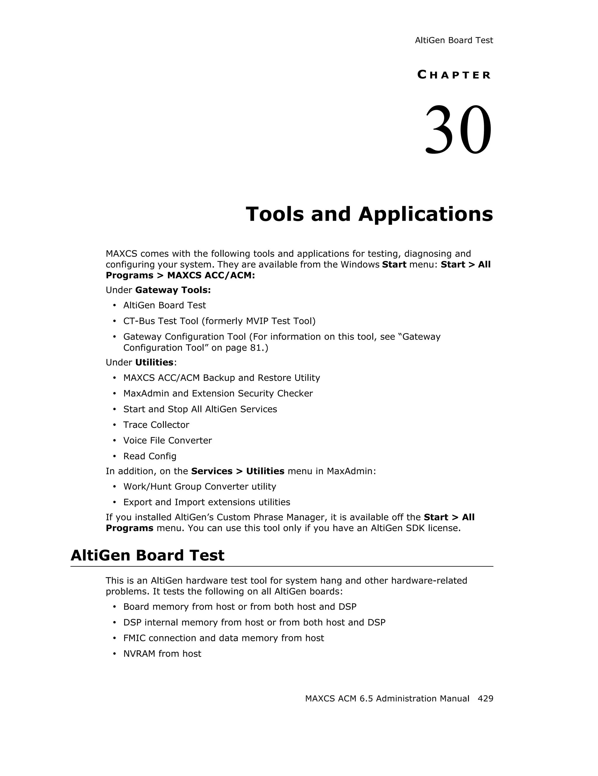
Audio Peripheral Configuration
You can configure audio peripheral settings:
• Music on hold
66 MAXCS ACM 6.5 Administration Manual](https://image.slidesharecdn.com/maxcsacm6-5administrationmanual-100910152521-phpapp02/75/AltiGen-M-A-X-C-S-A-C-M-6-80-2048.jpg)

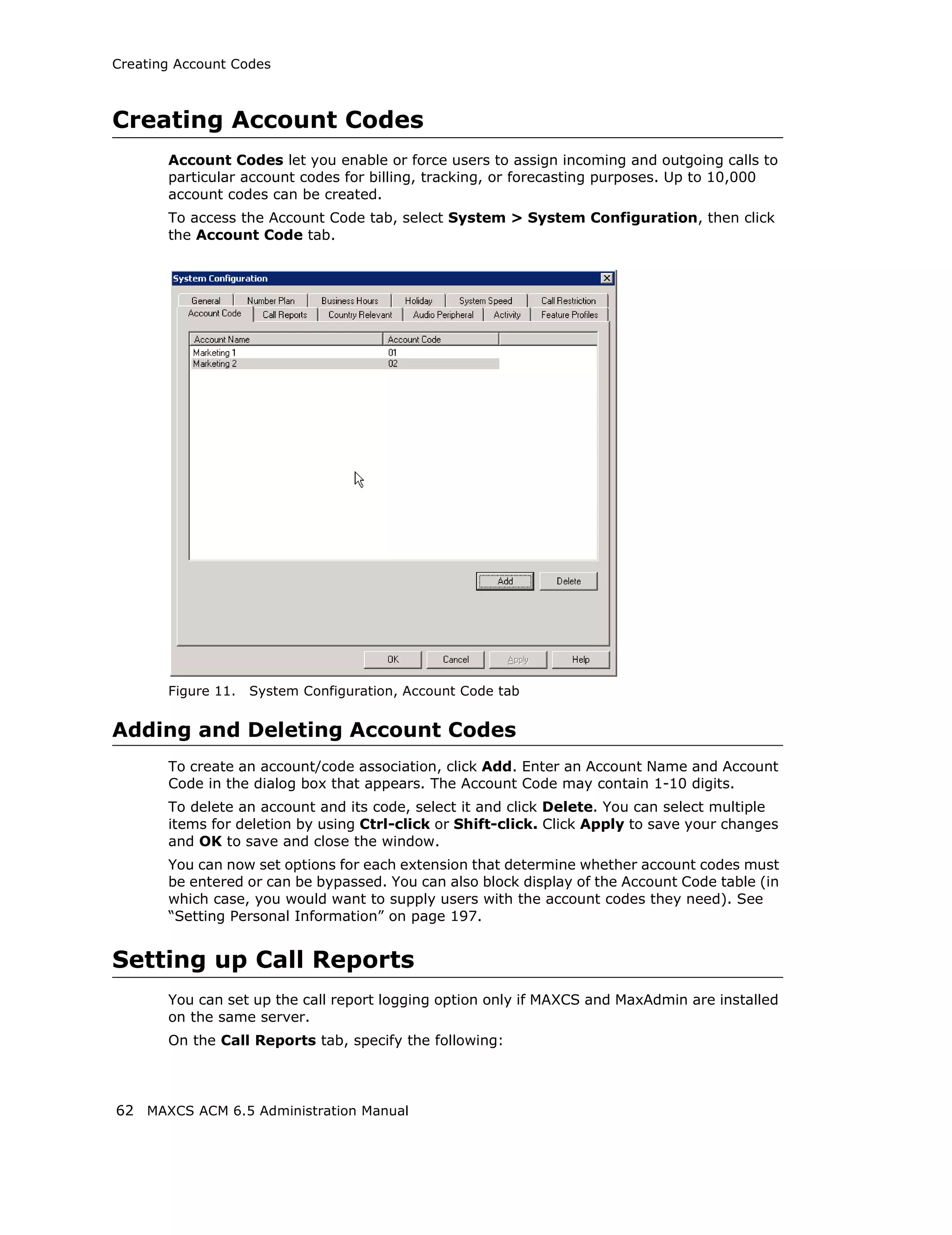
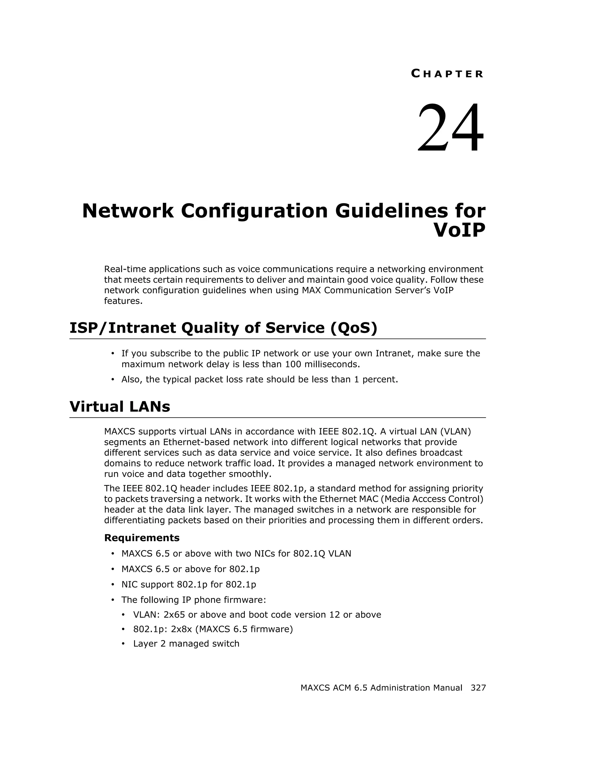
![Adding and Attaching a Gateway
Parameter Description
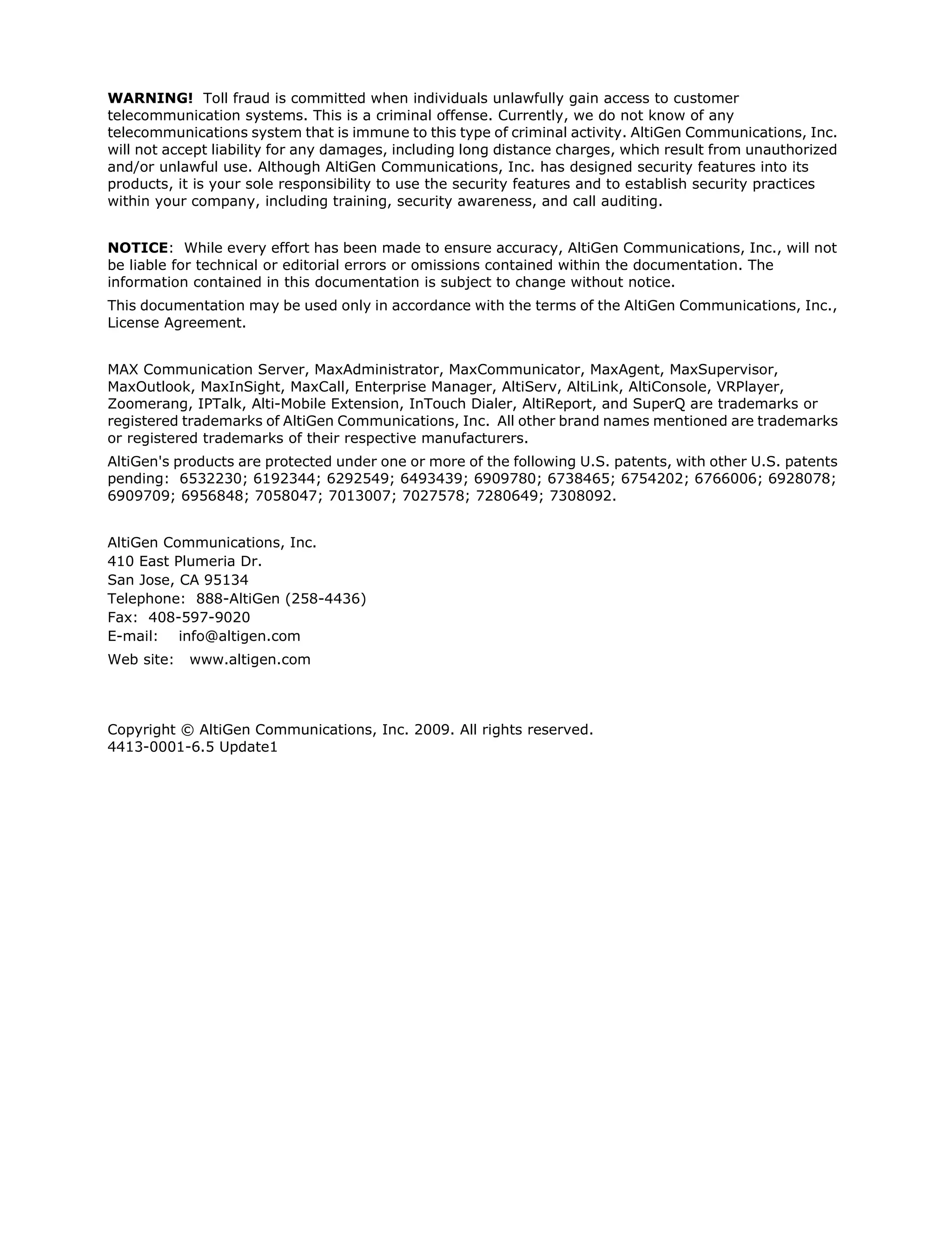
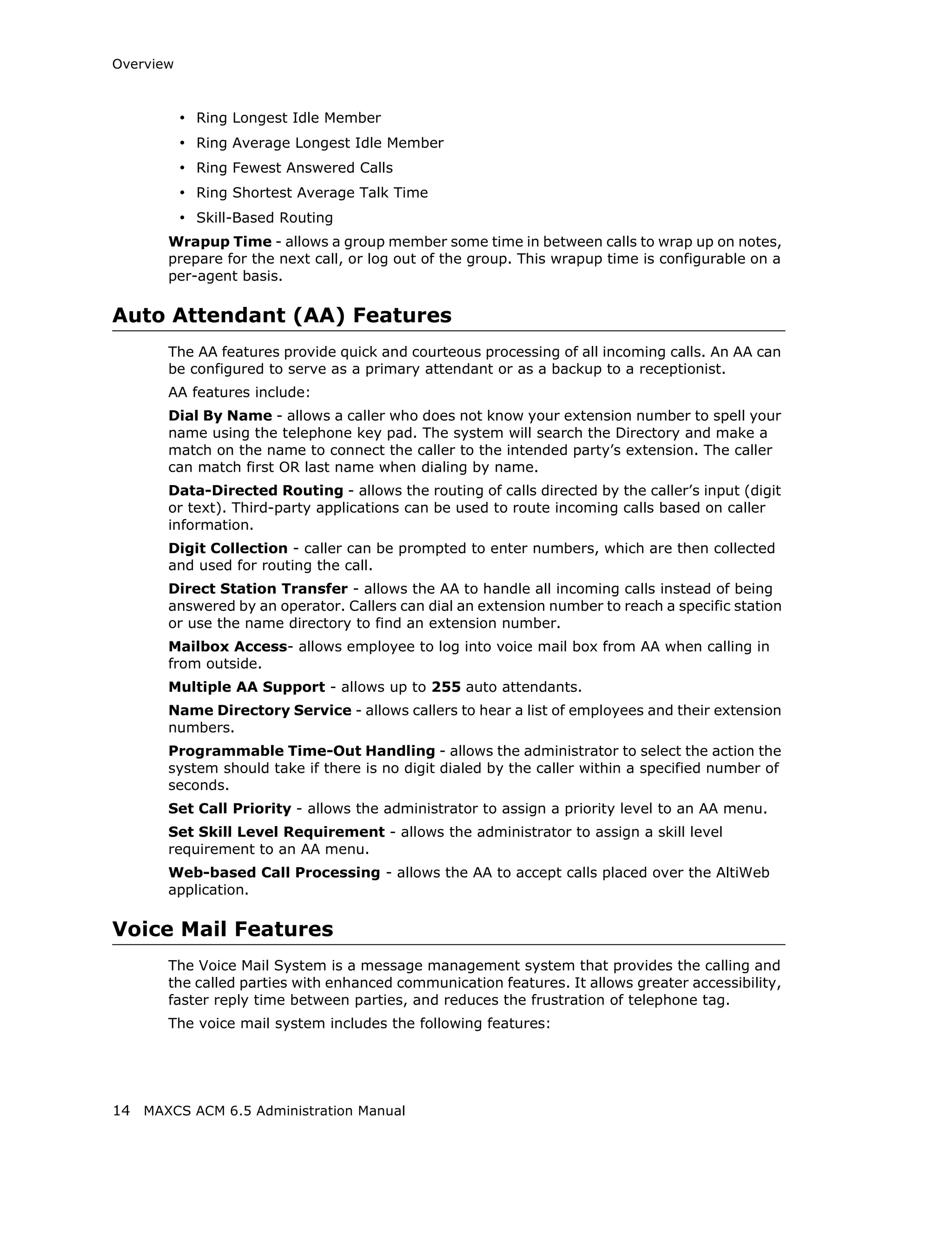
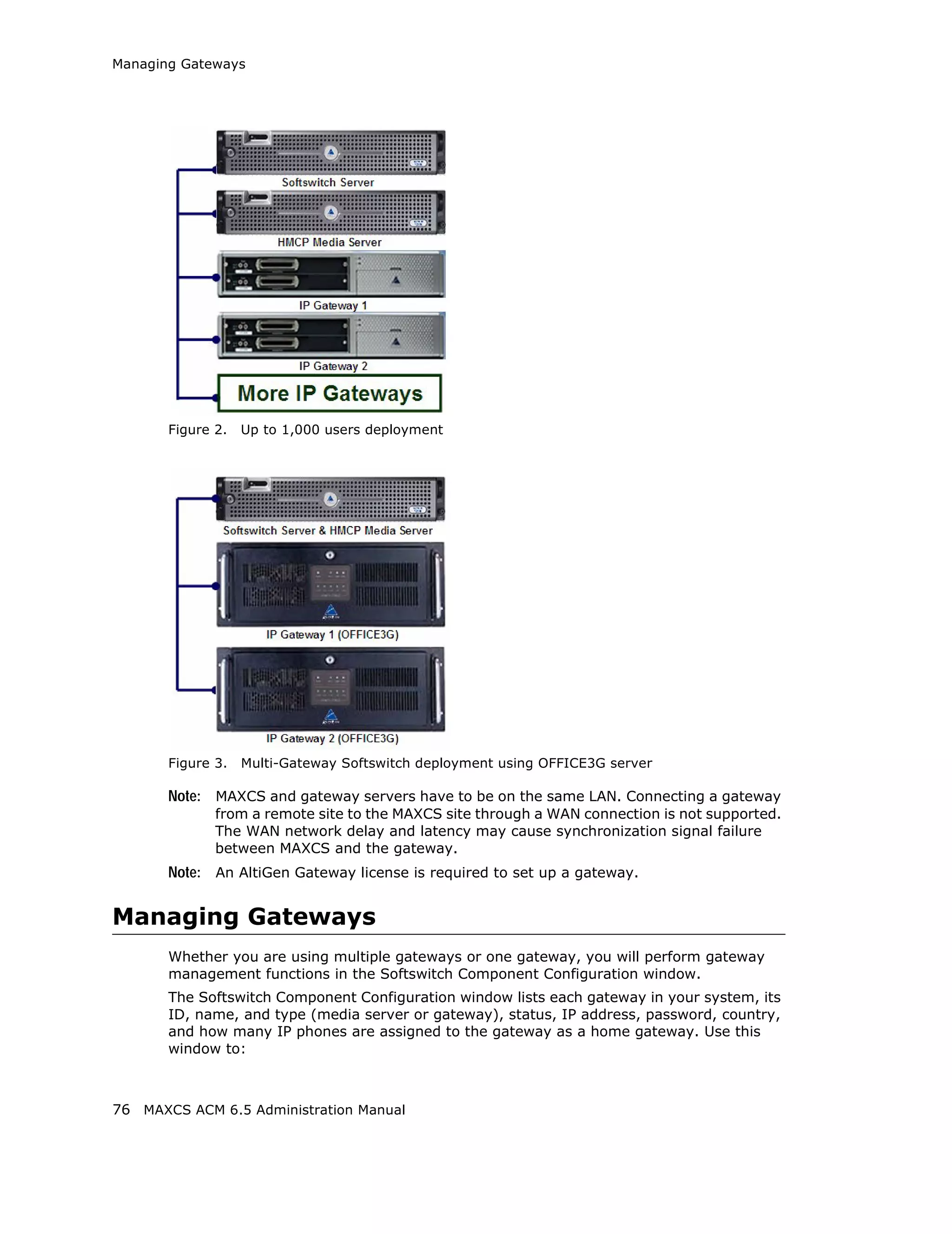
Set CT-Bus Clock This parameter determines which telephony
board will provide the clock signal for the TDM
bus. If you don't have multiple T1 or E1 boards
in a gateway, the default Auto setting is
recommended. The system will find the
appropriate board to supply the clock. If you
have multiple T1 or E1 boards in a gateway, the
system will automatically select the one with the
lowest logical board ID as the clock source.
However, in some circumstances, you may need
to manually change to other boards. For
example:
1. If multiple T1/E1 boards are in the gateway
and the T1/E1 board that has been selected
automatically is not active.
2. If the T1/E1 board that has been selected
automatically is set up as a tie trunk to
another system, and the T1/E1 connecting to
the CO is on the other board.
Board button [Not used at this time]
Refresh button Refreshes the selected gateway’s (read-only)
status display
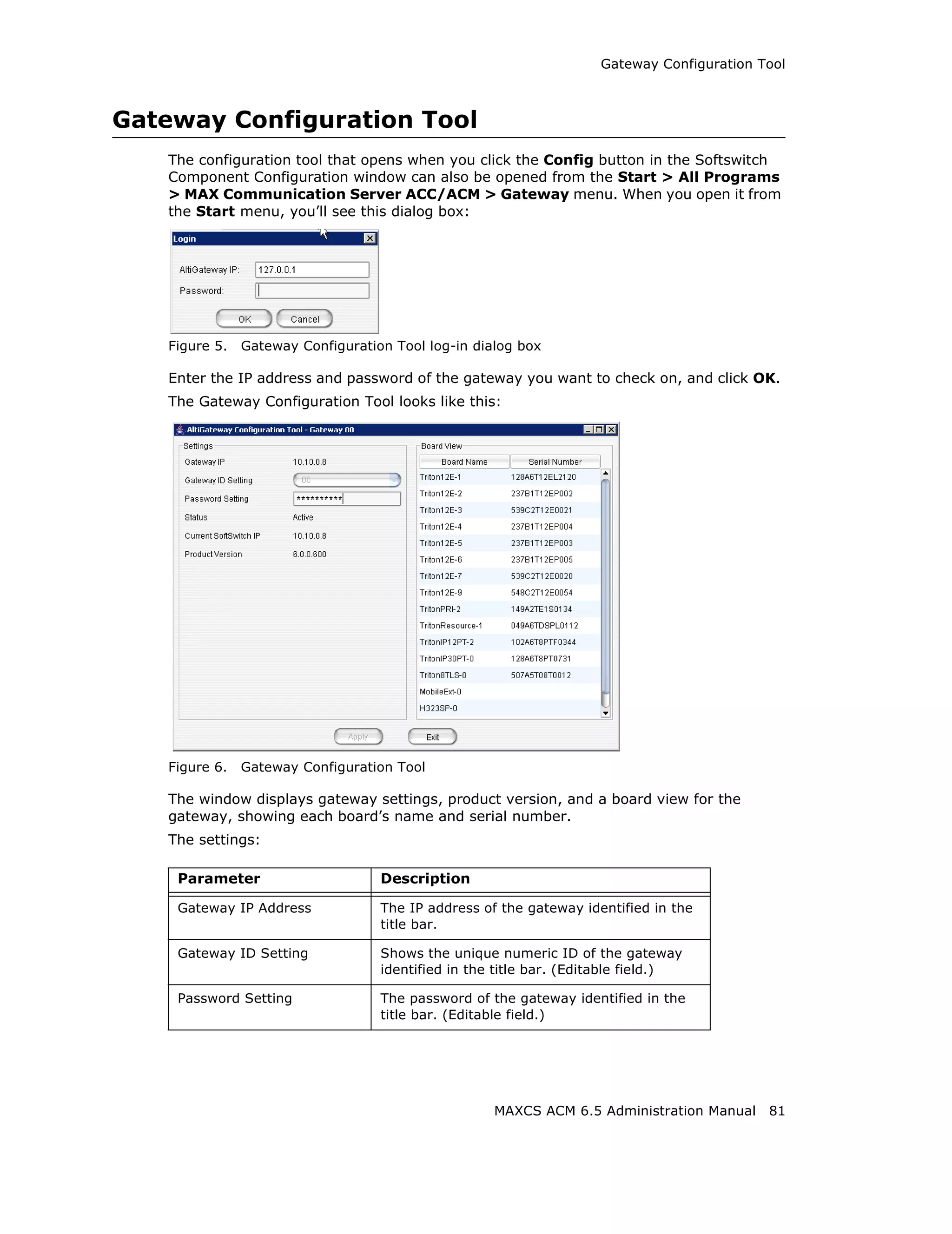
Config button Opens the AltiGateway Configuration Tool,
where you can see information on the selected
gateway and change the gateway ID and
password for this gateway.
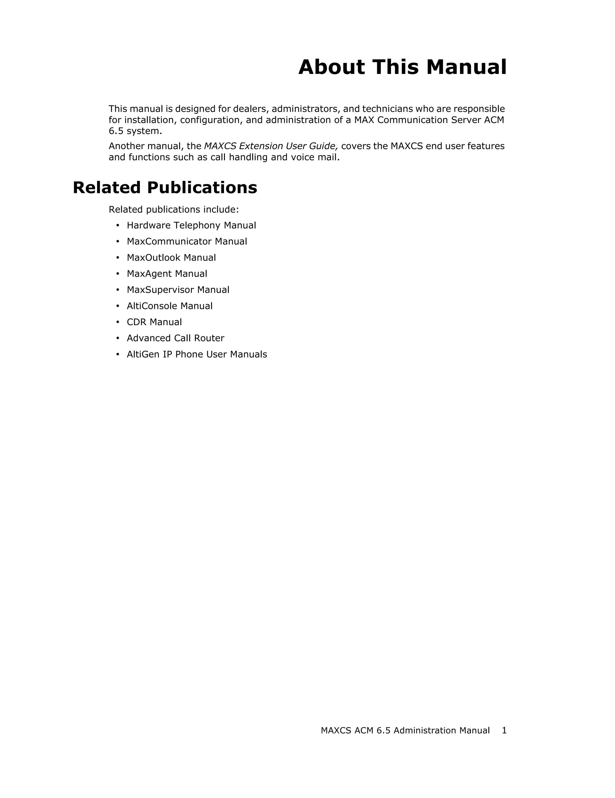
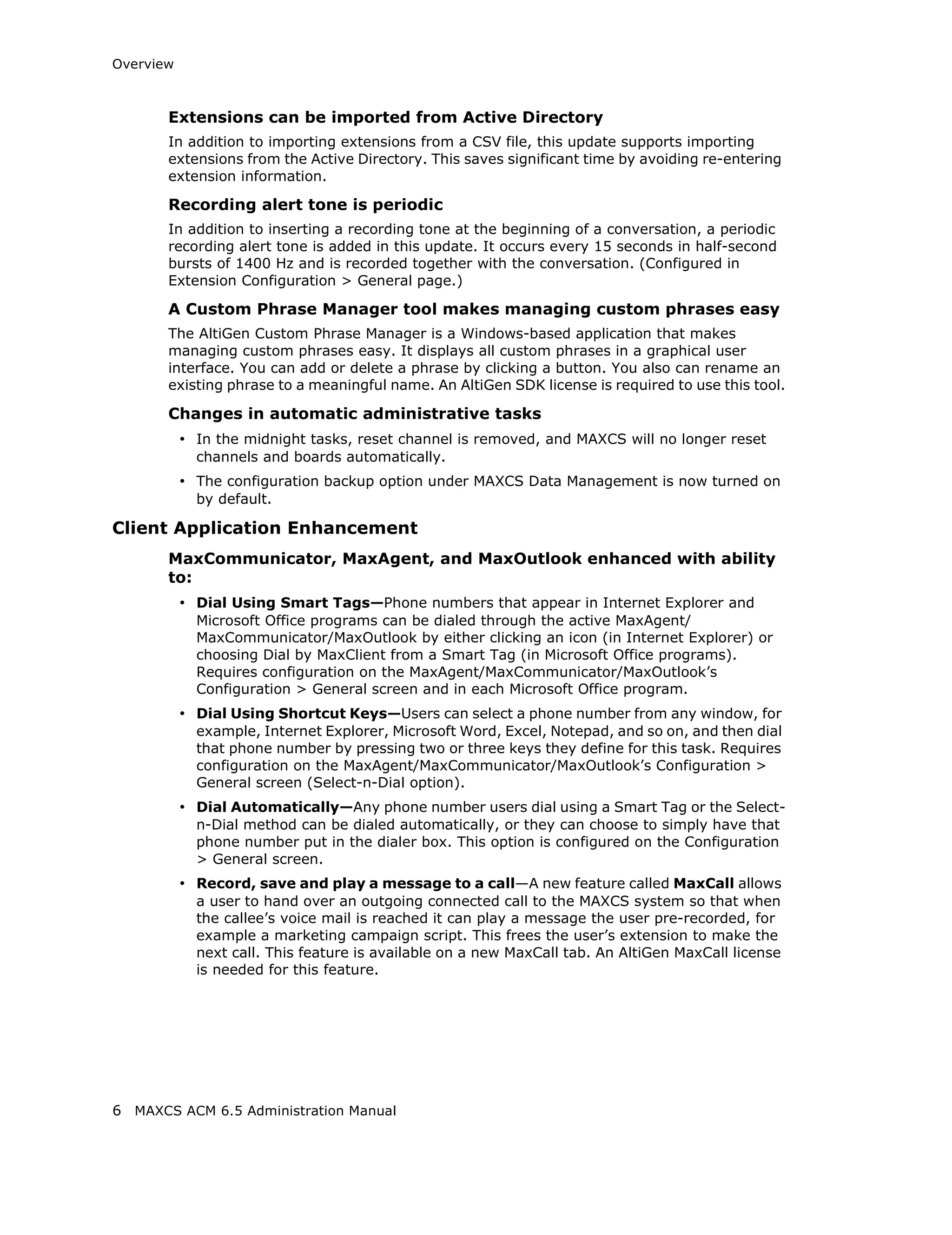
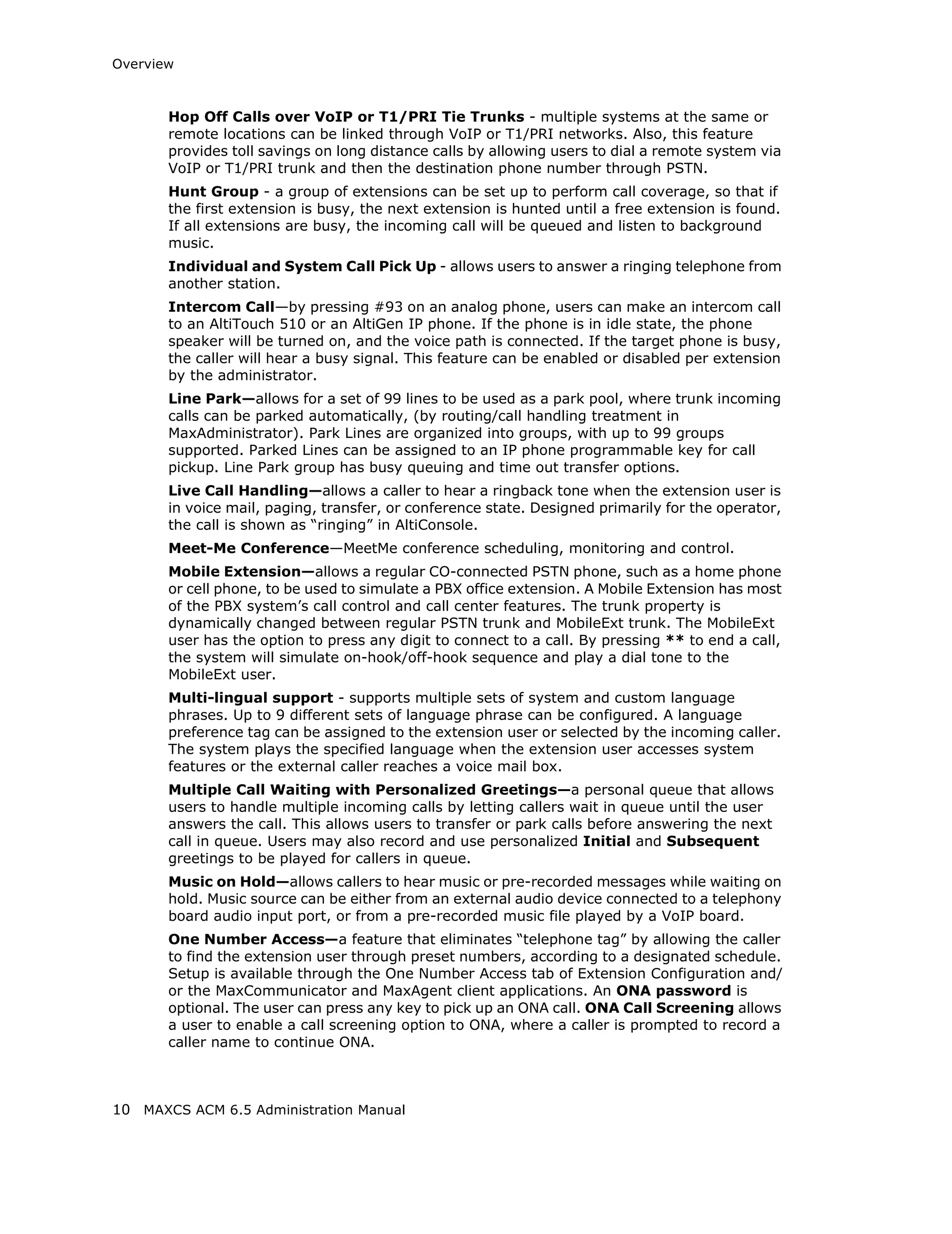
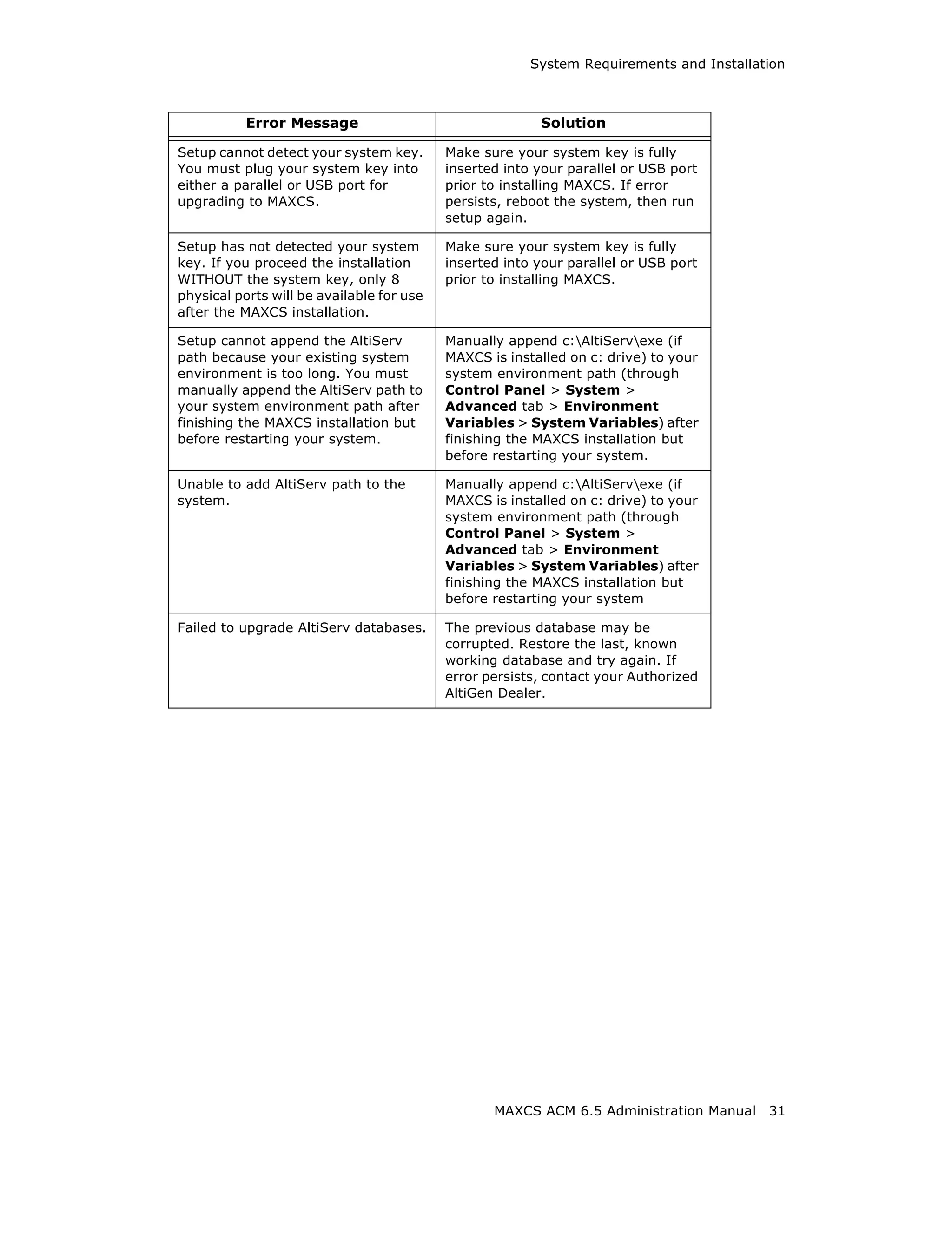
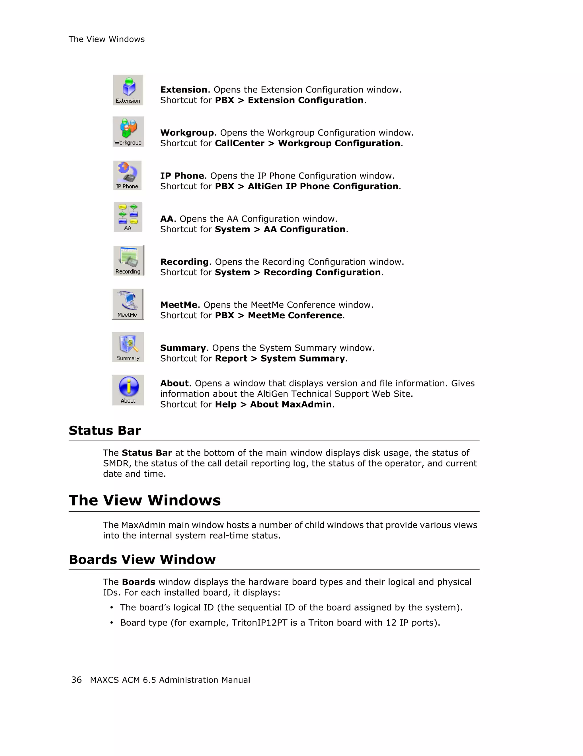
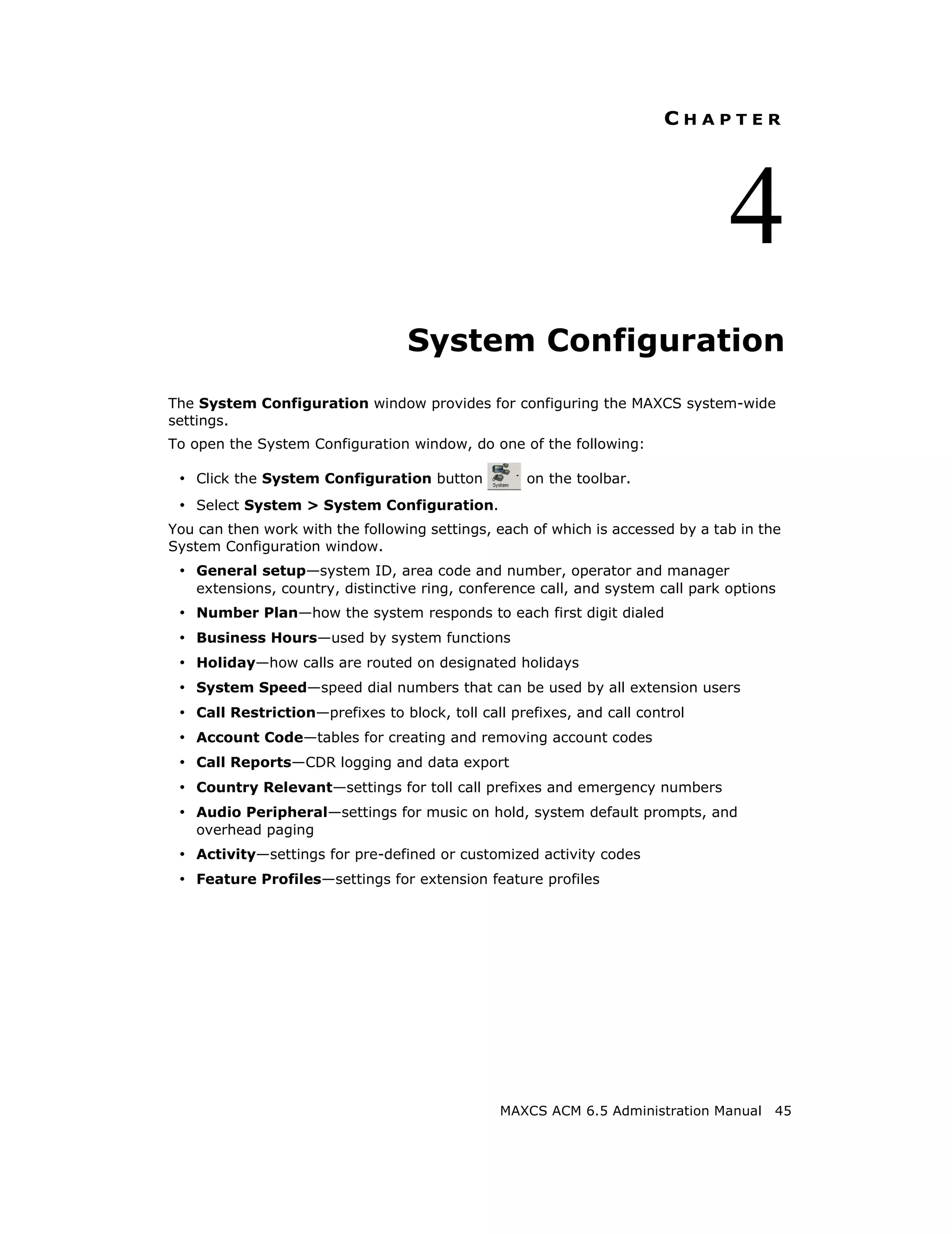
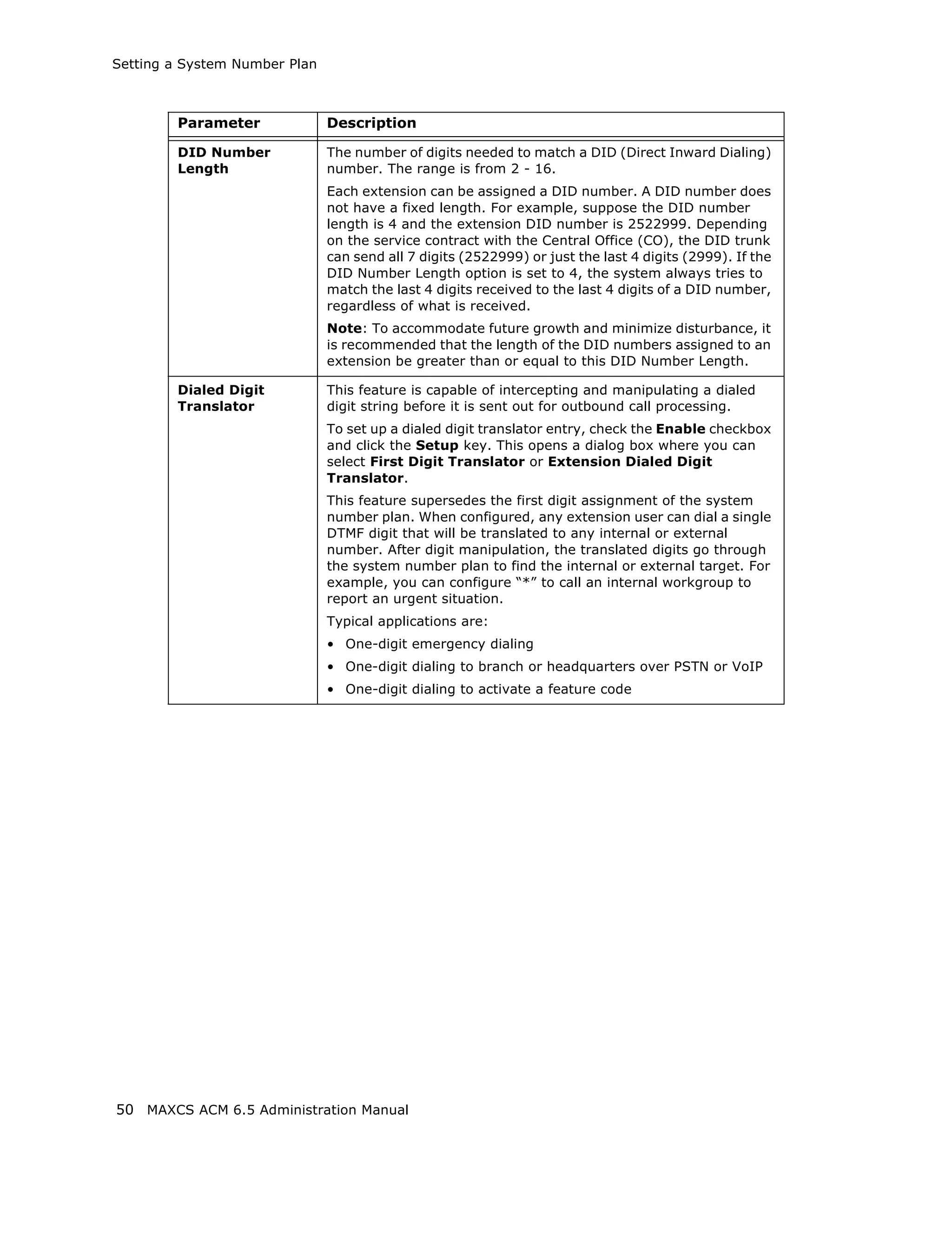
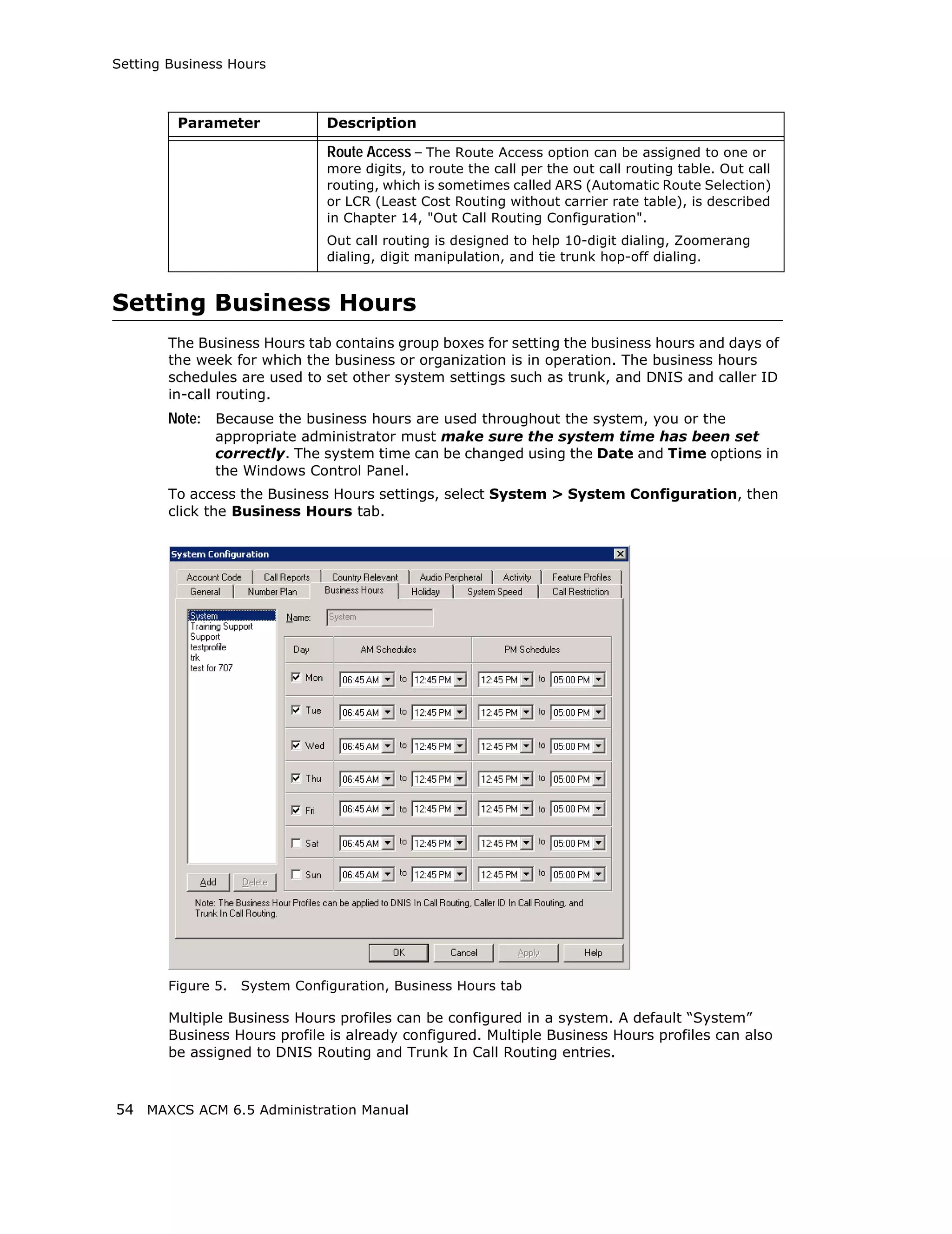
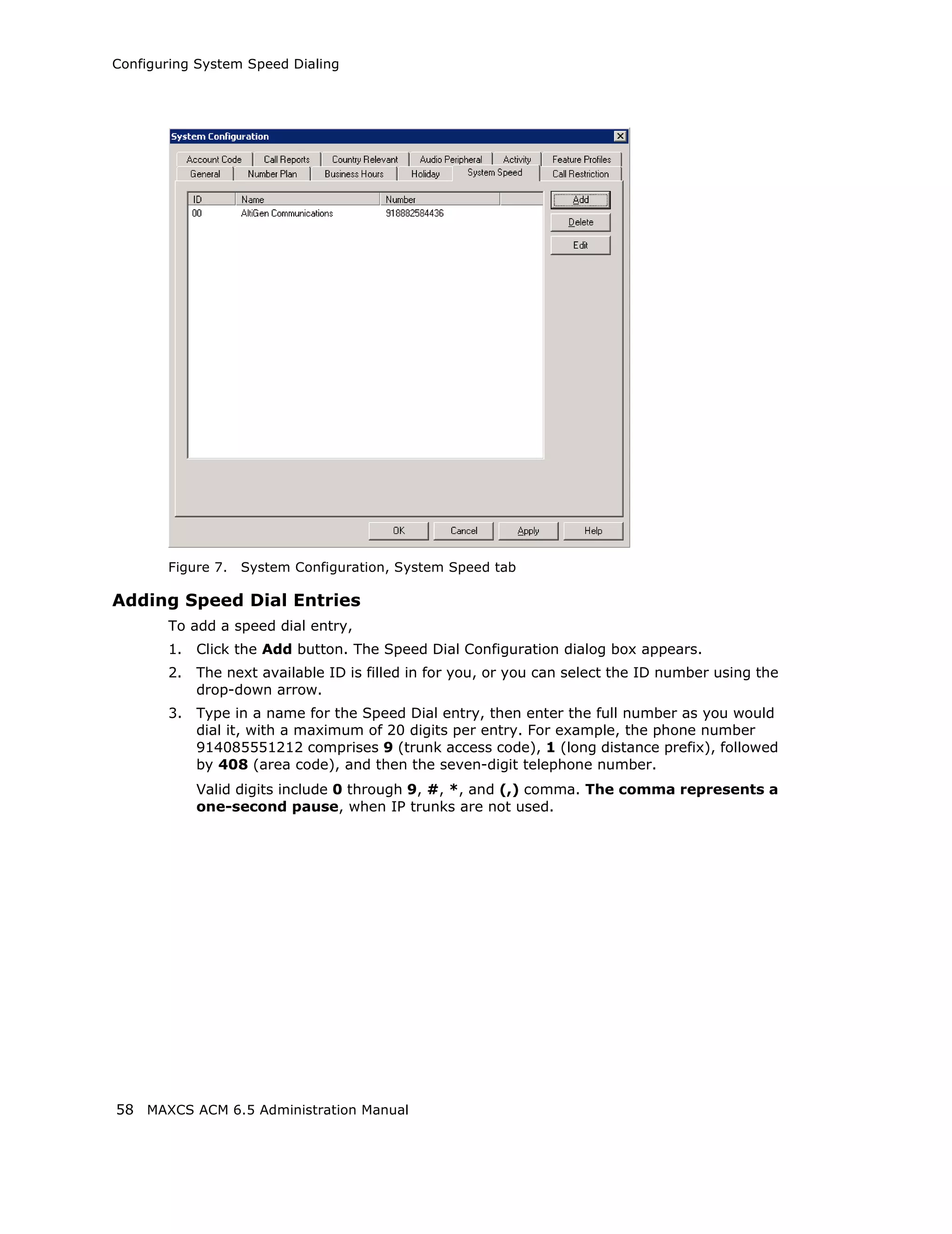
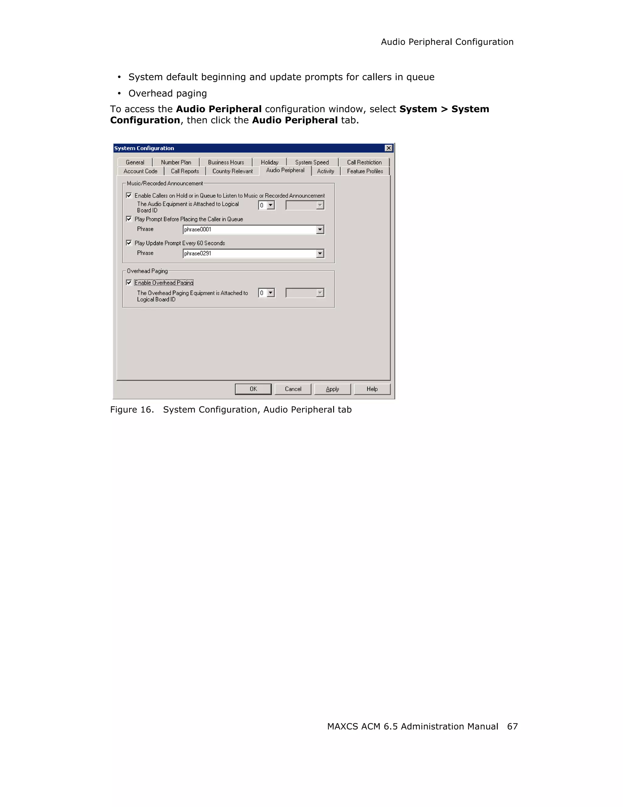
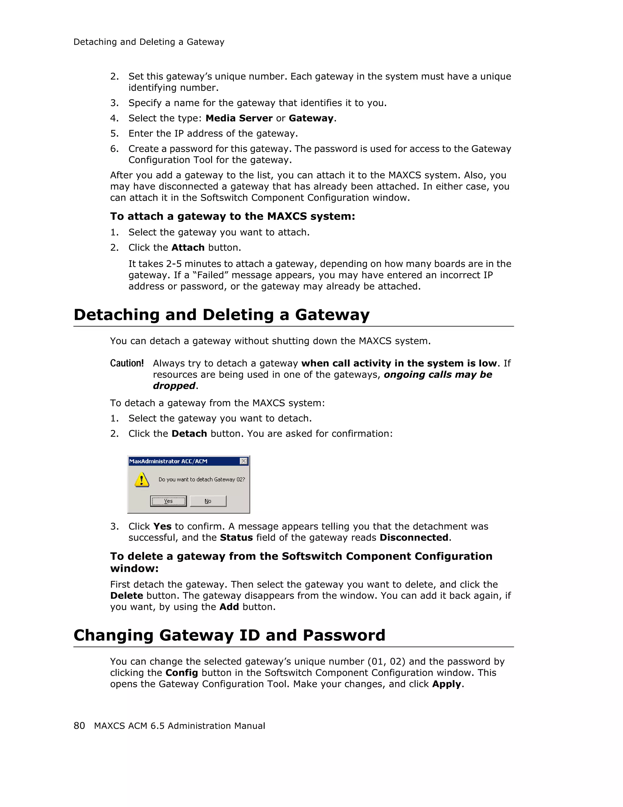
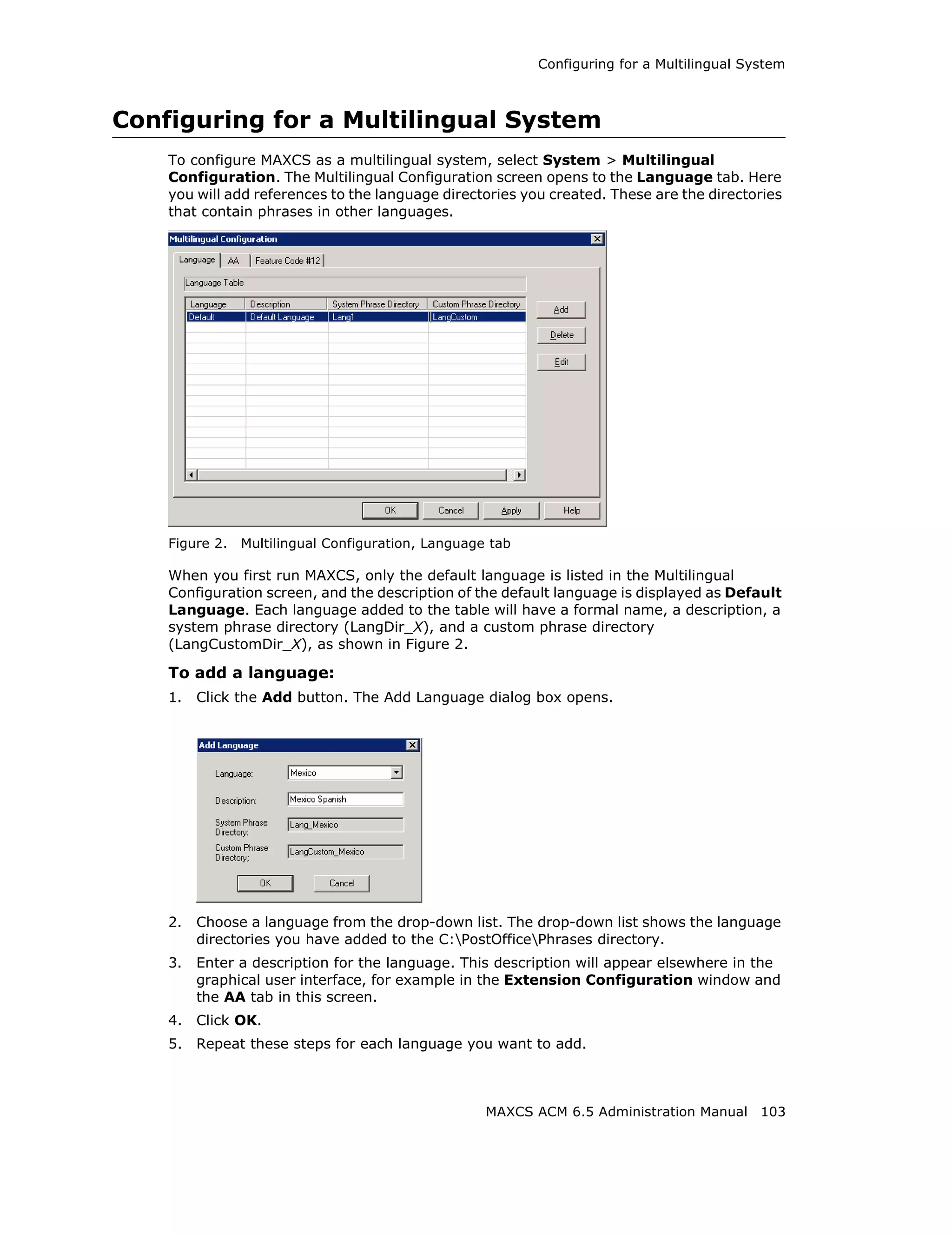
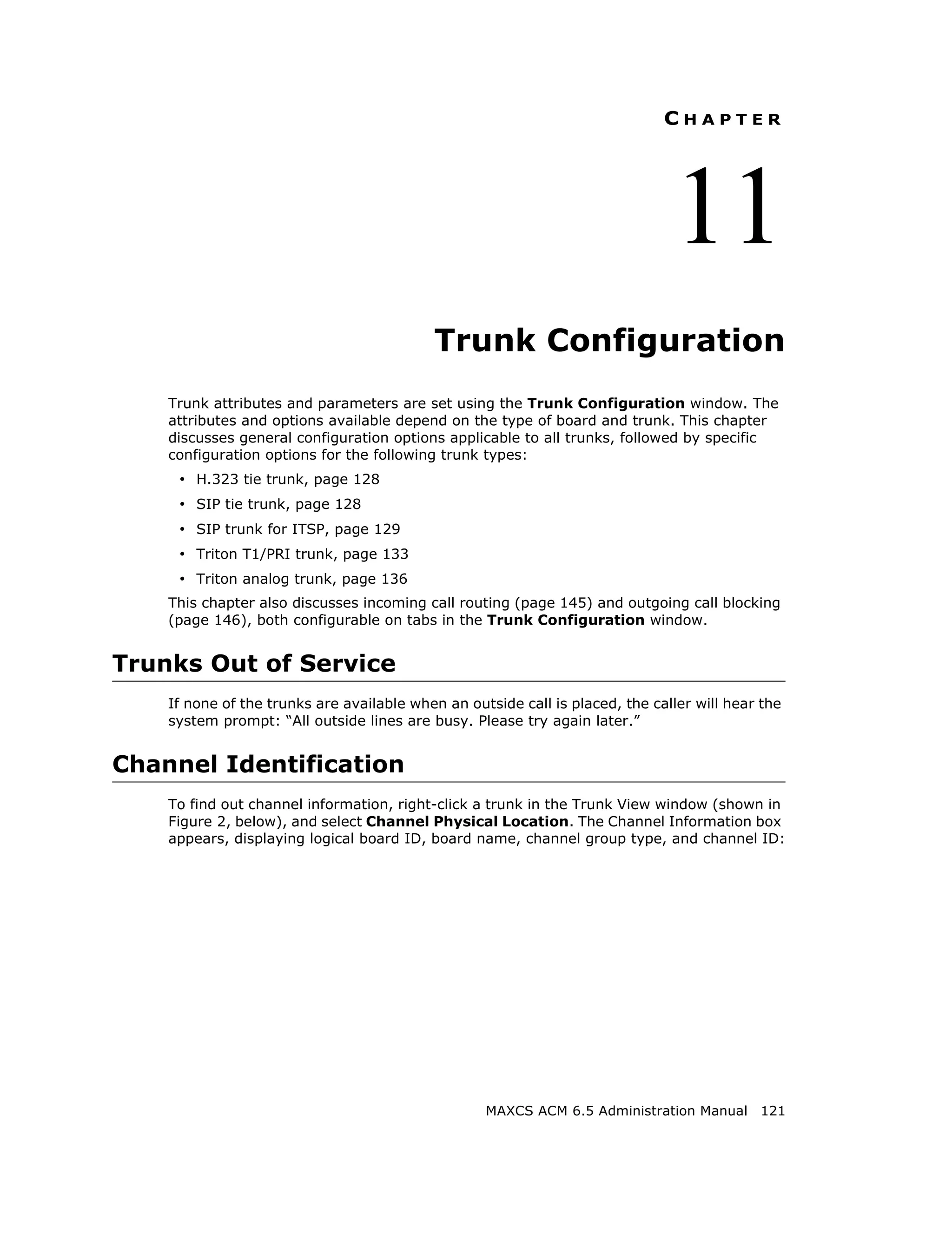
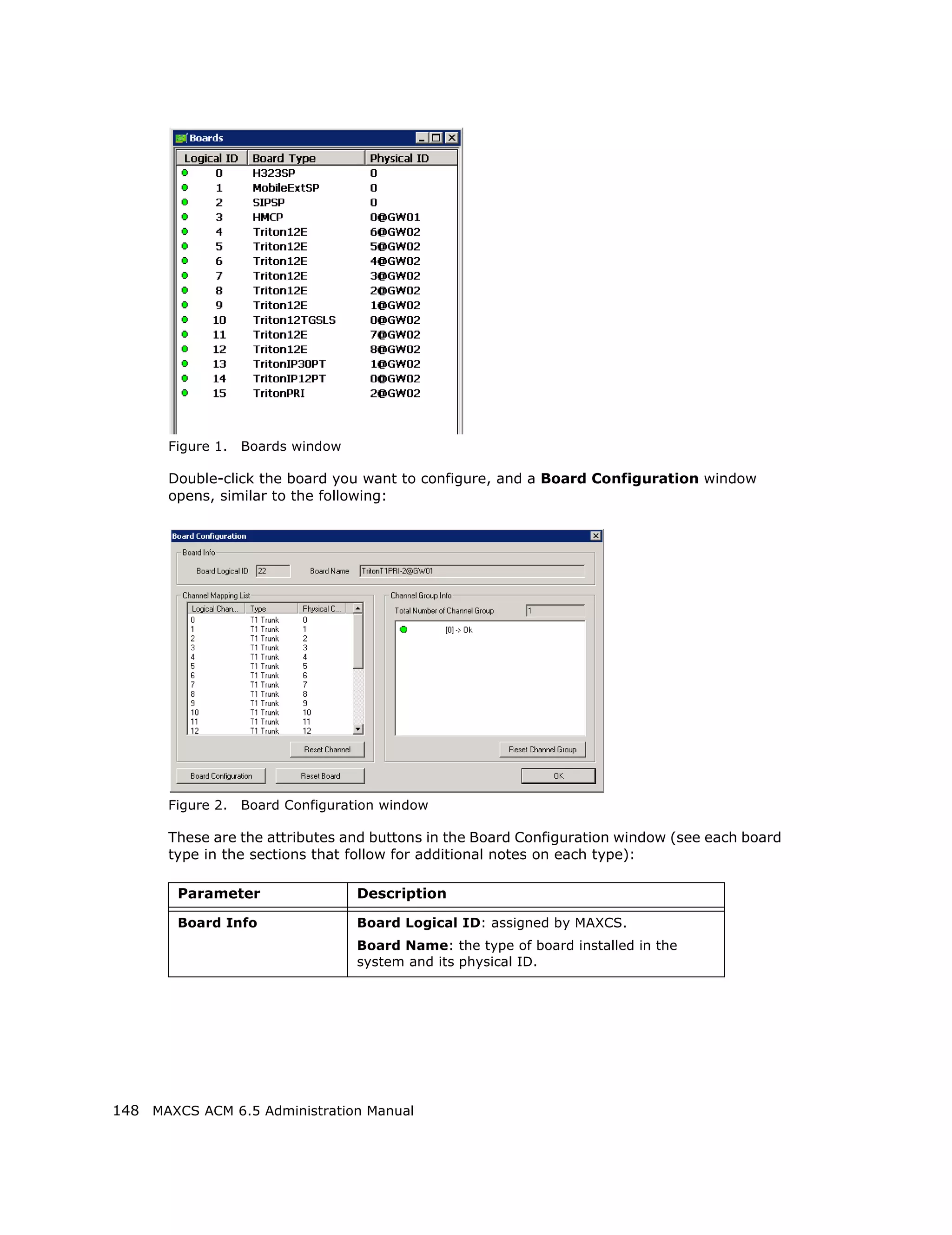
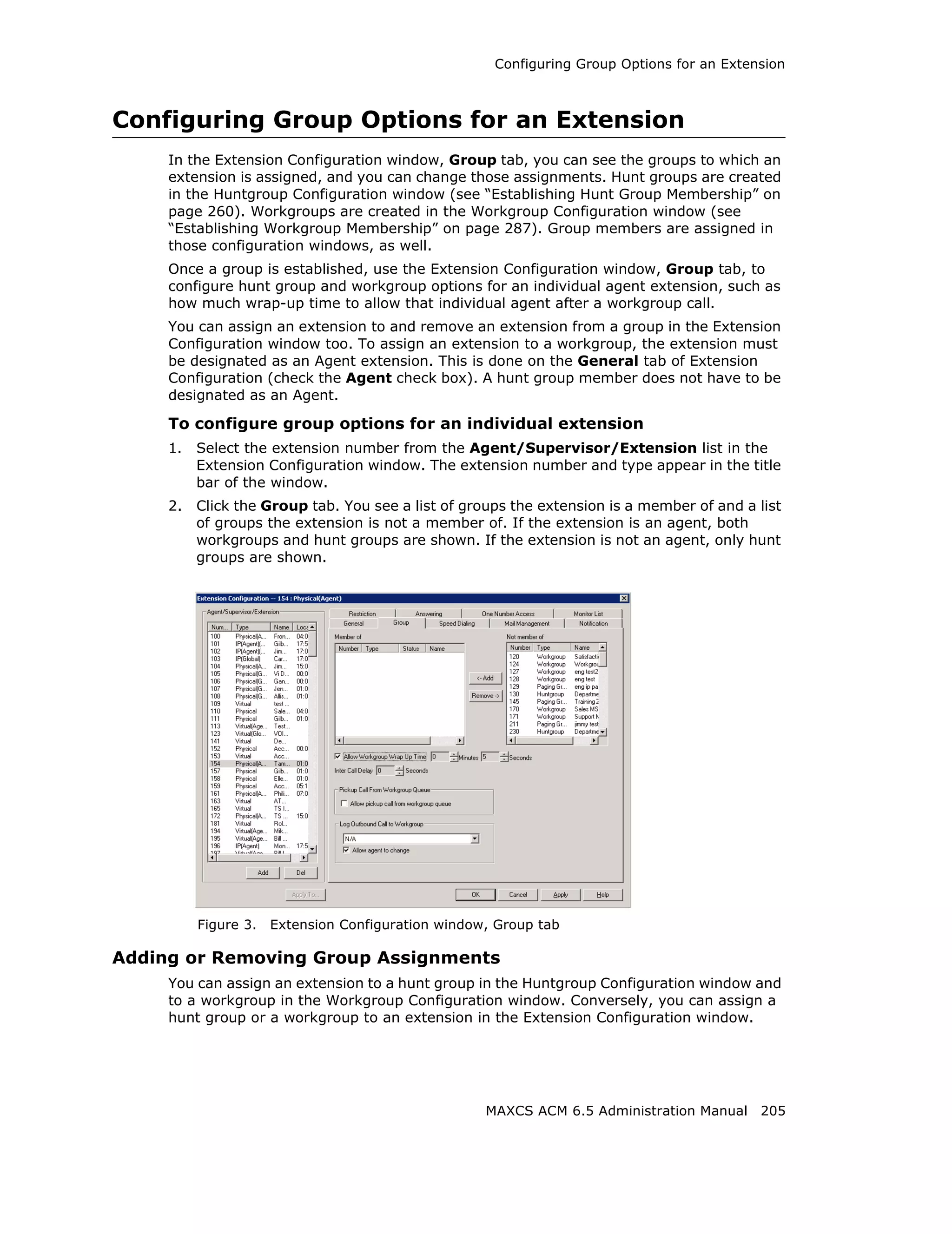
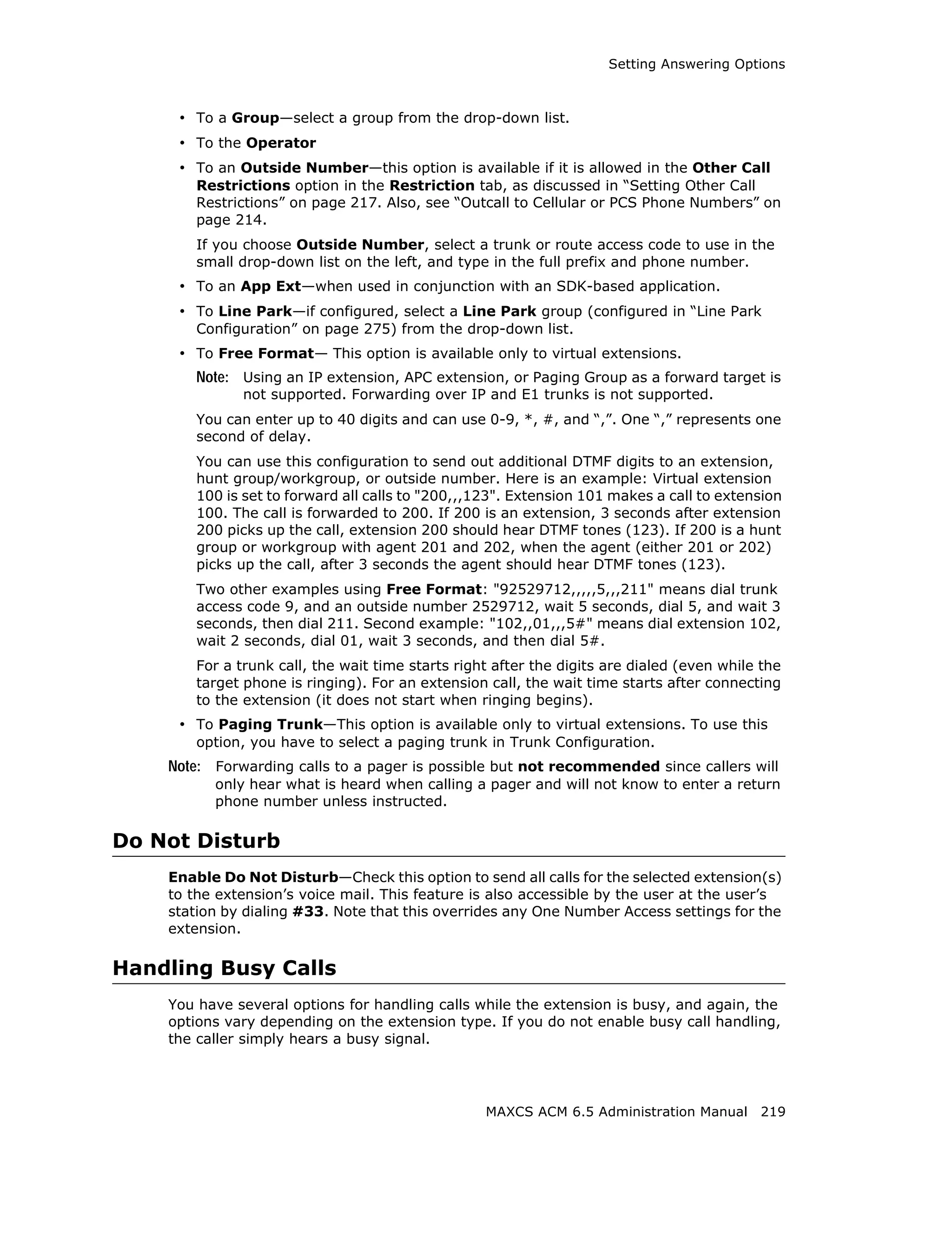
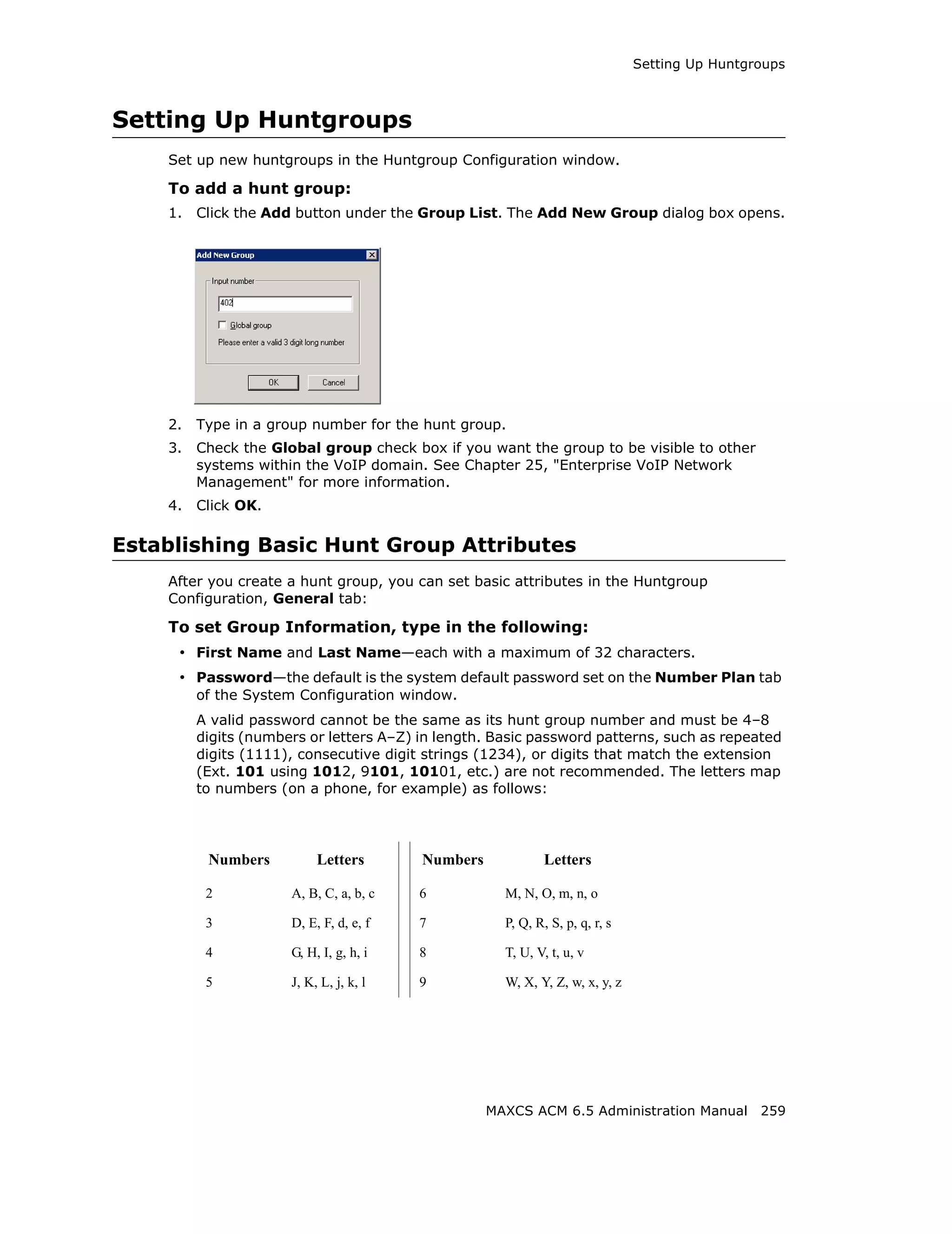
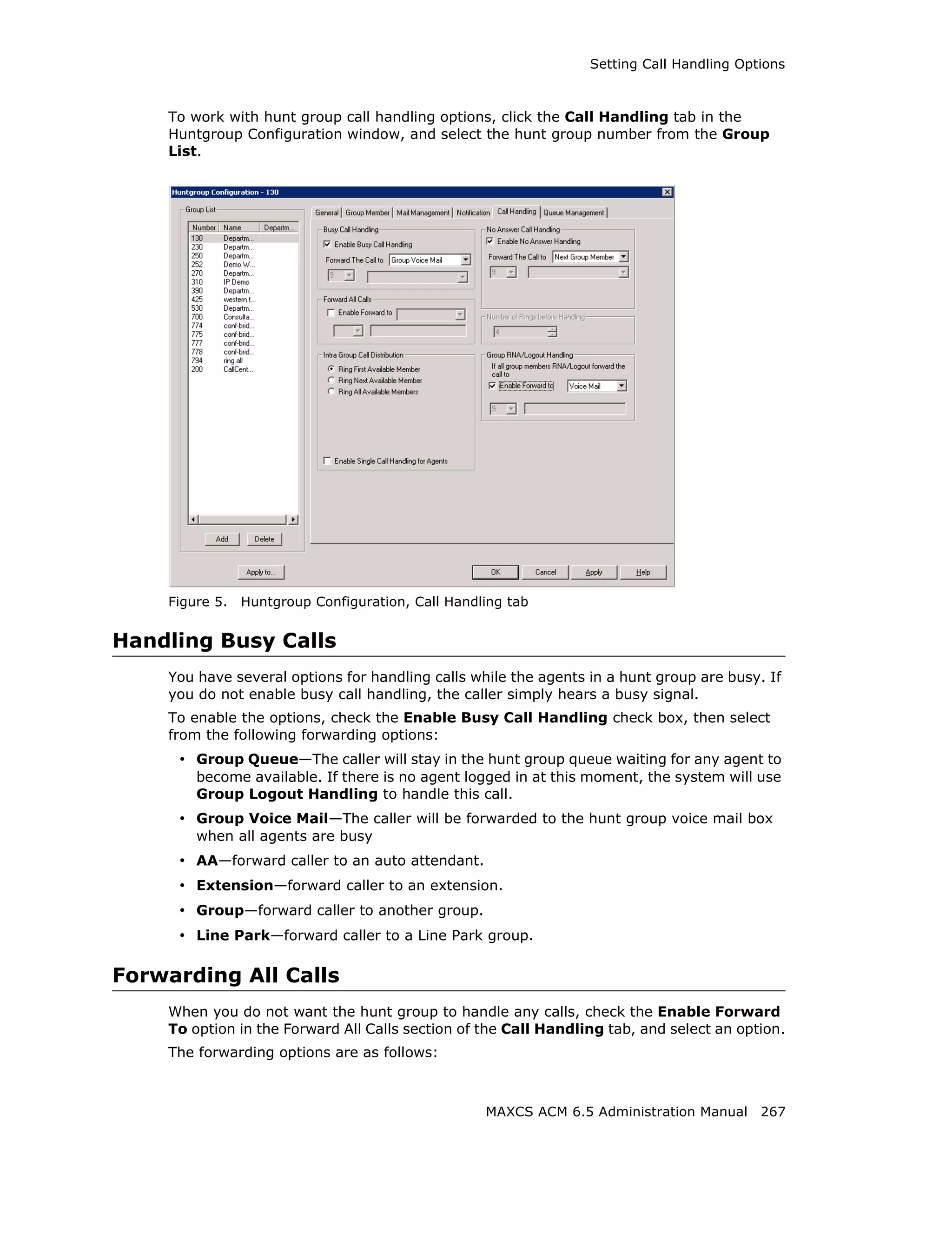
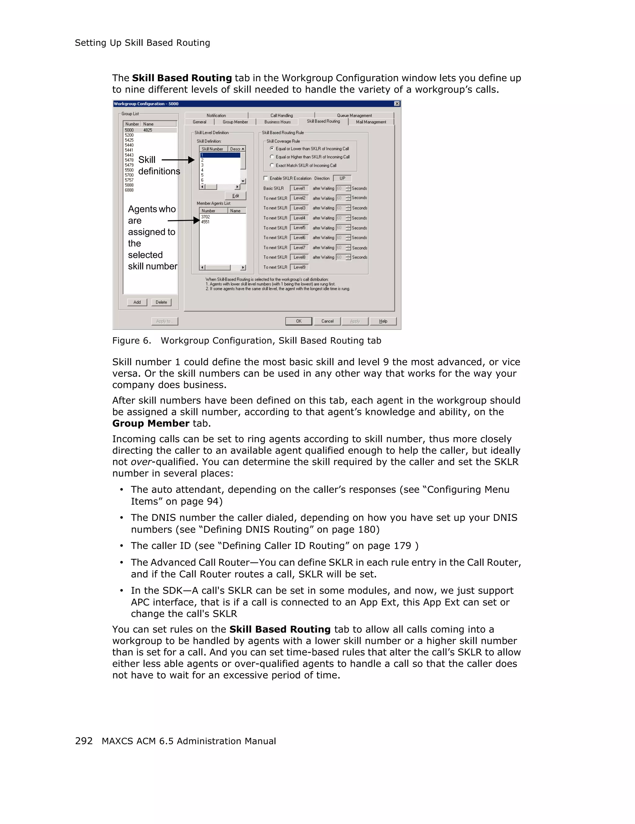
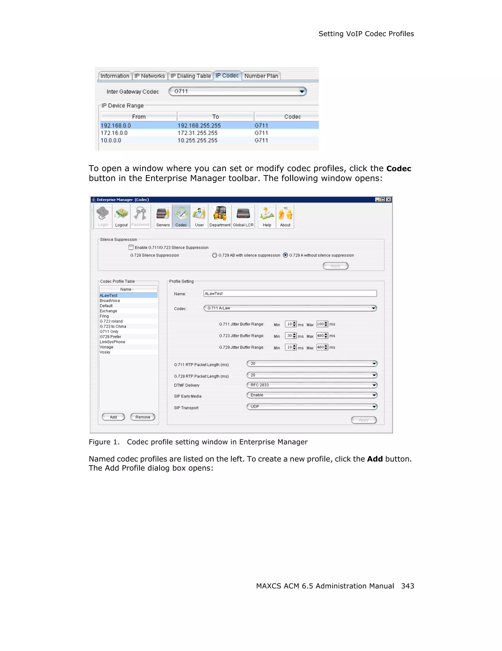
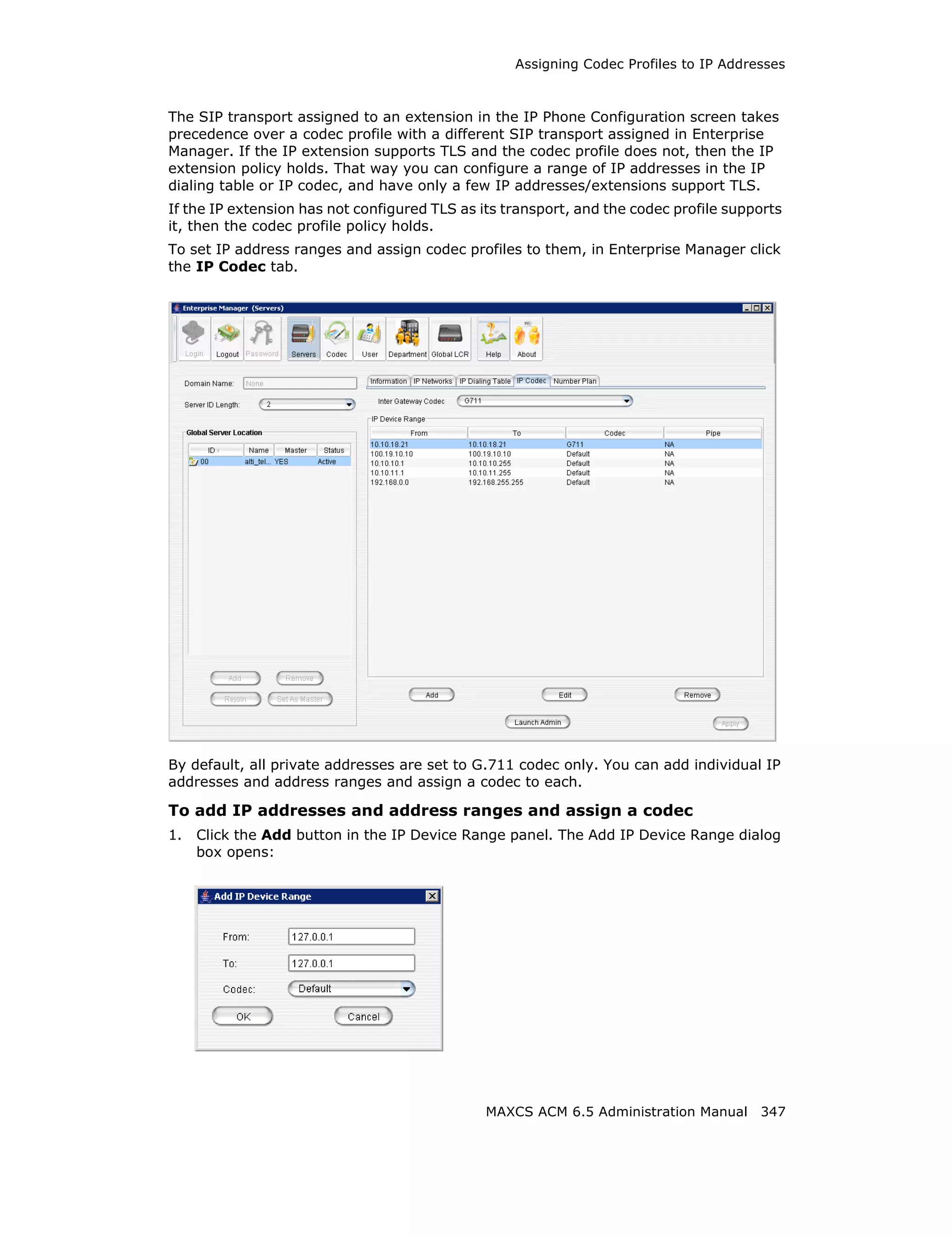
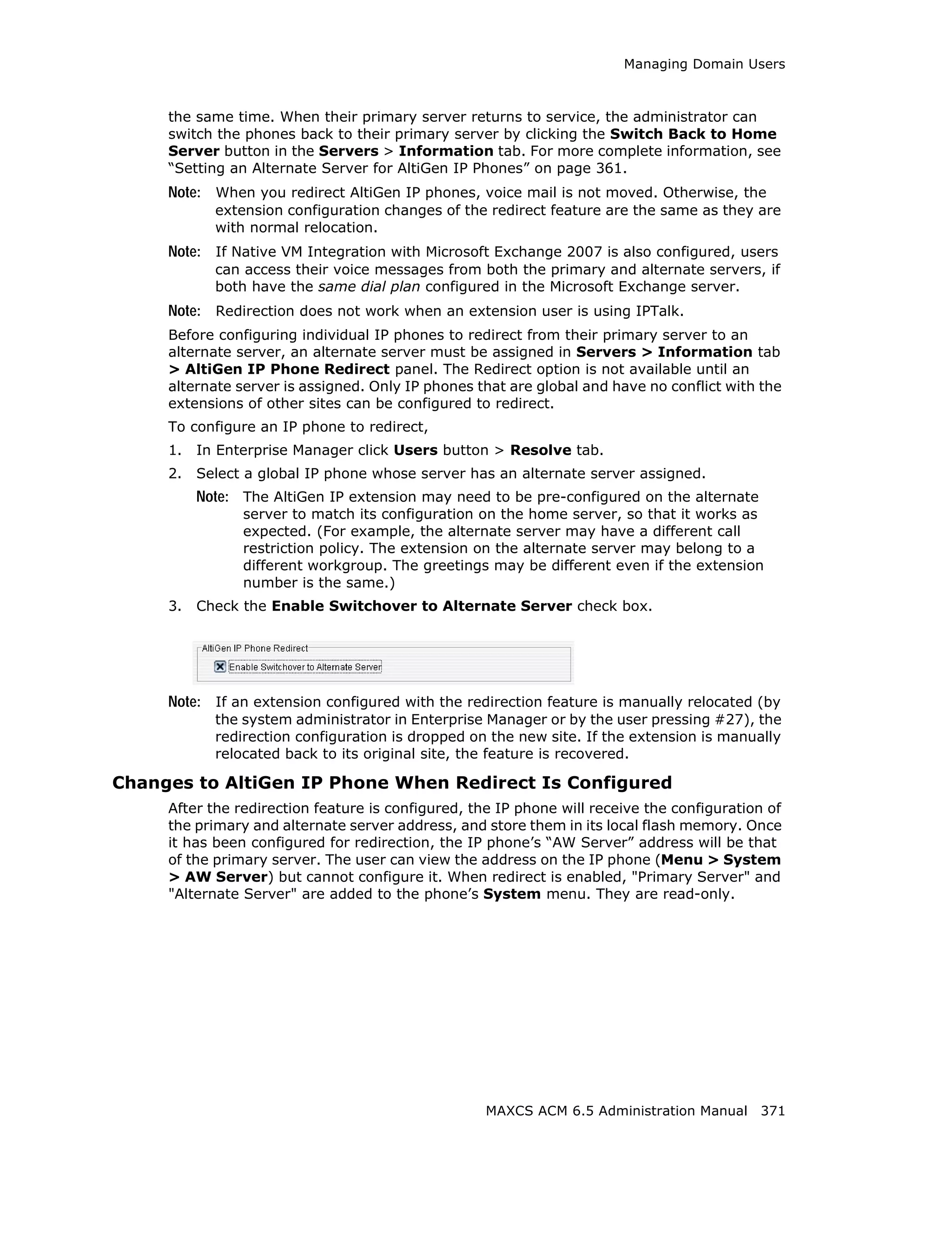
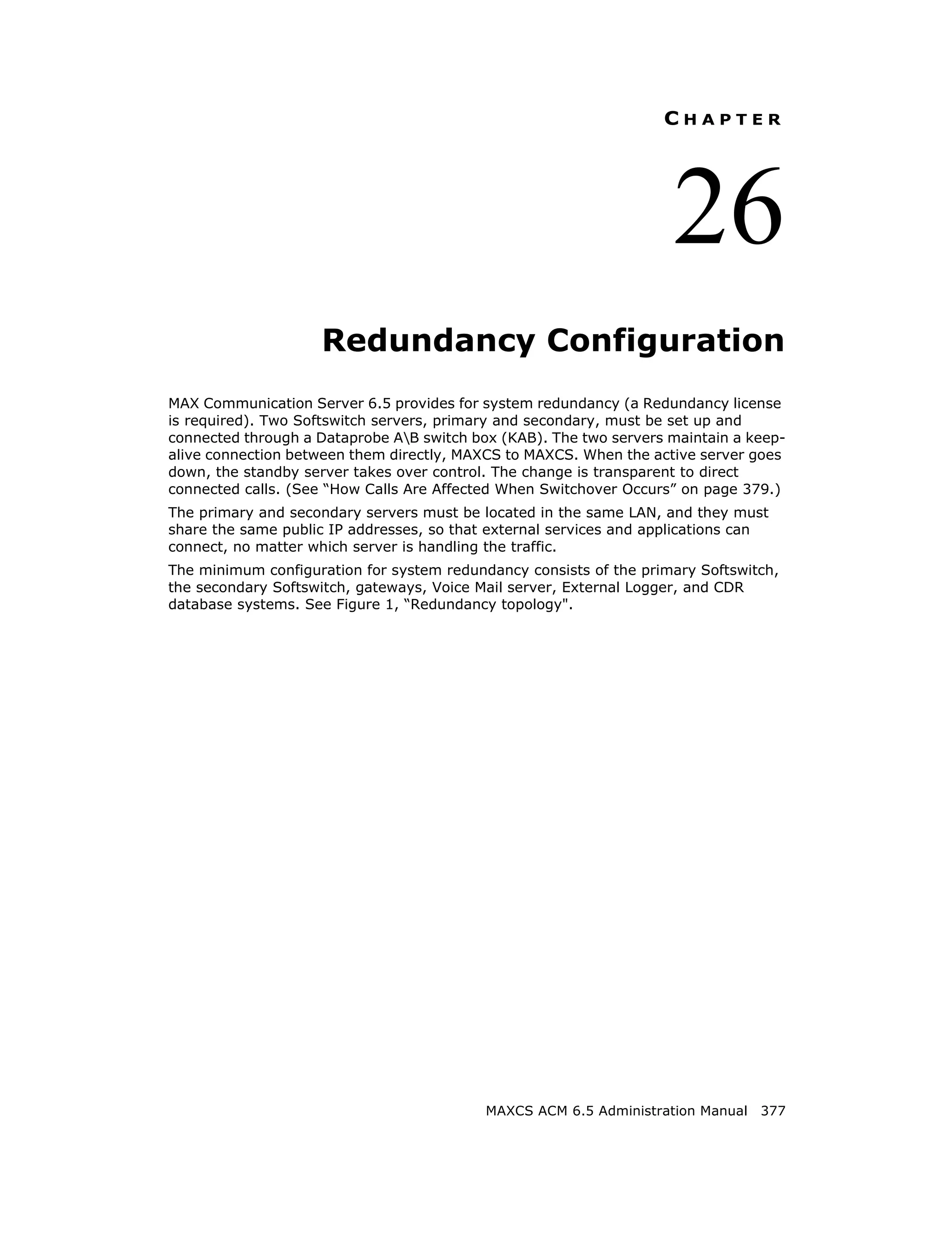
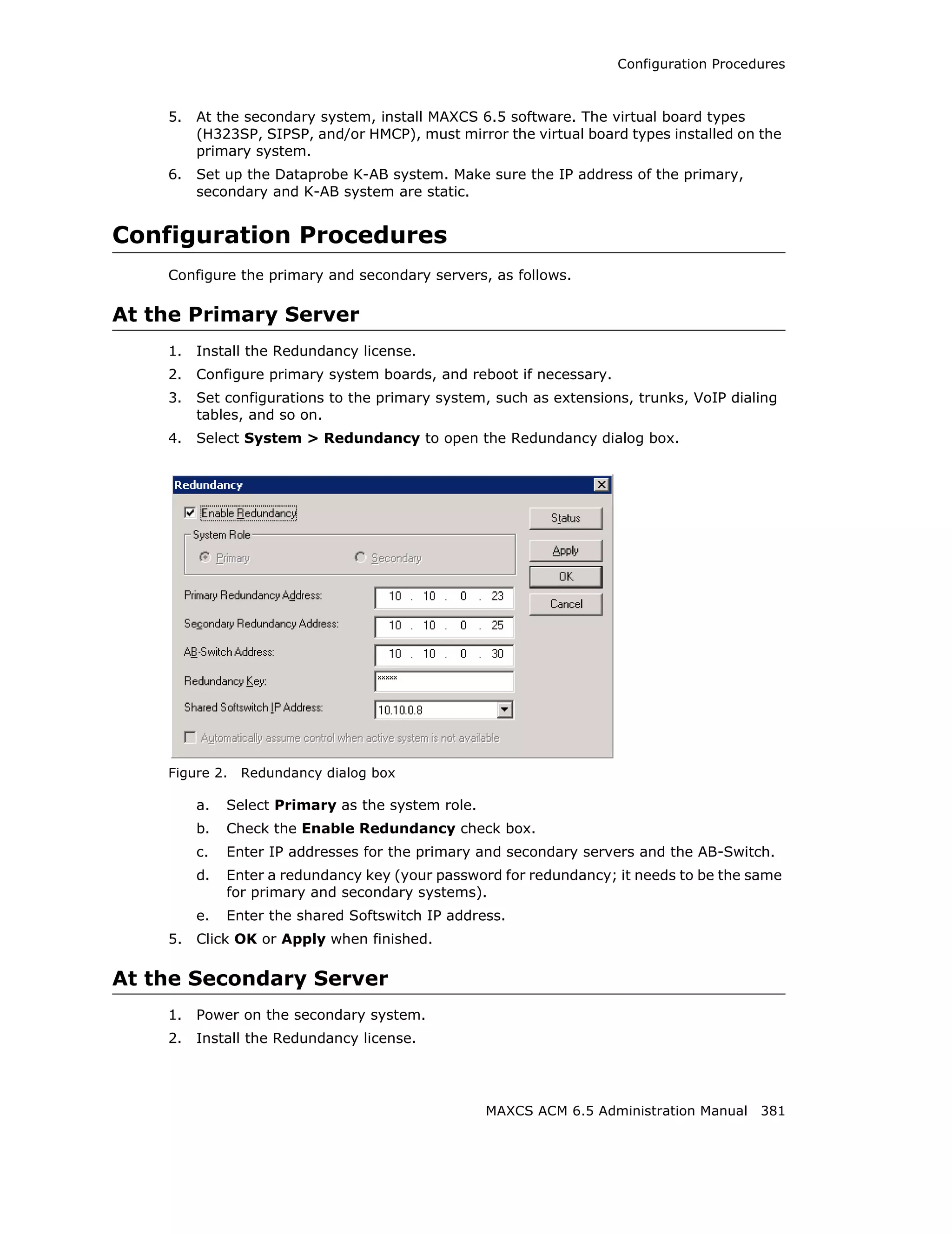
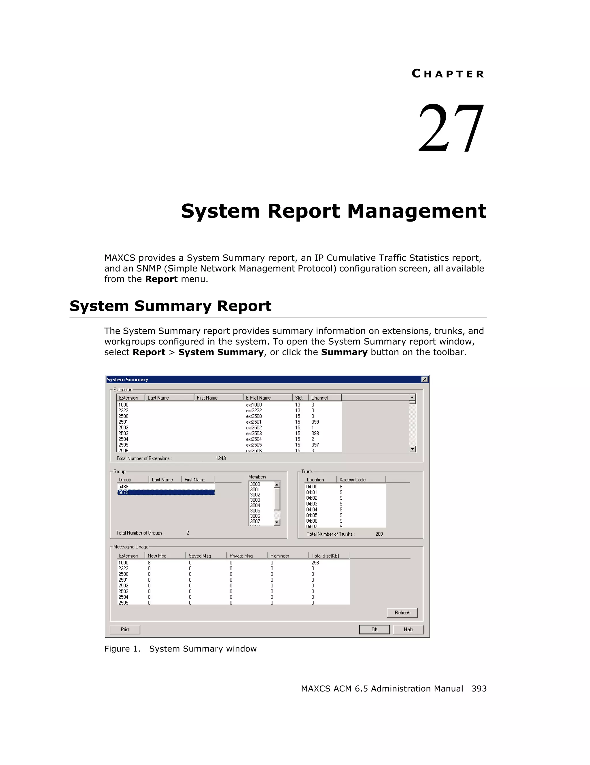
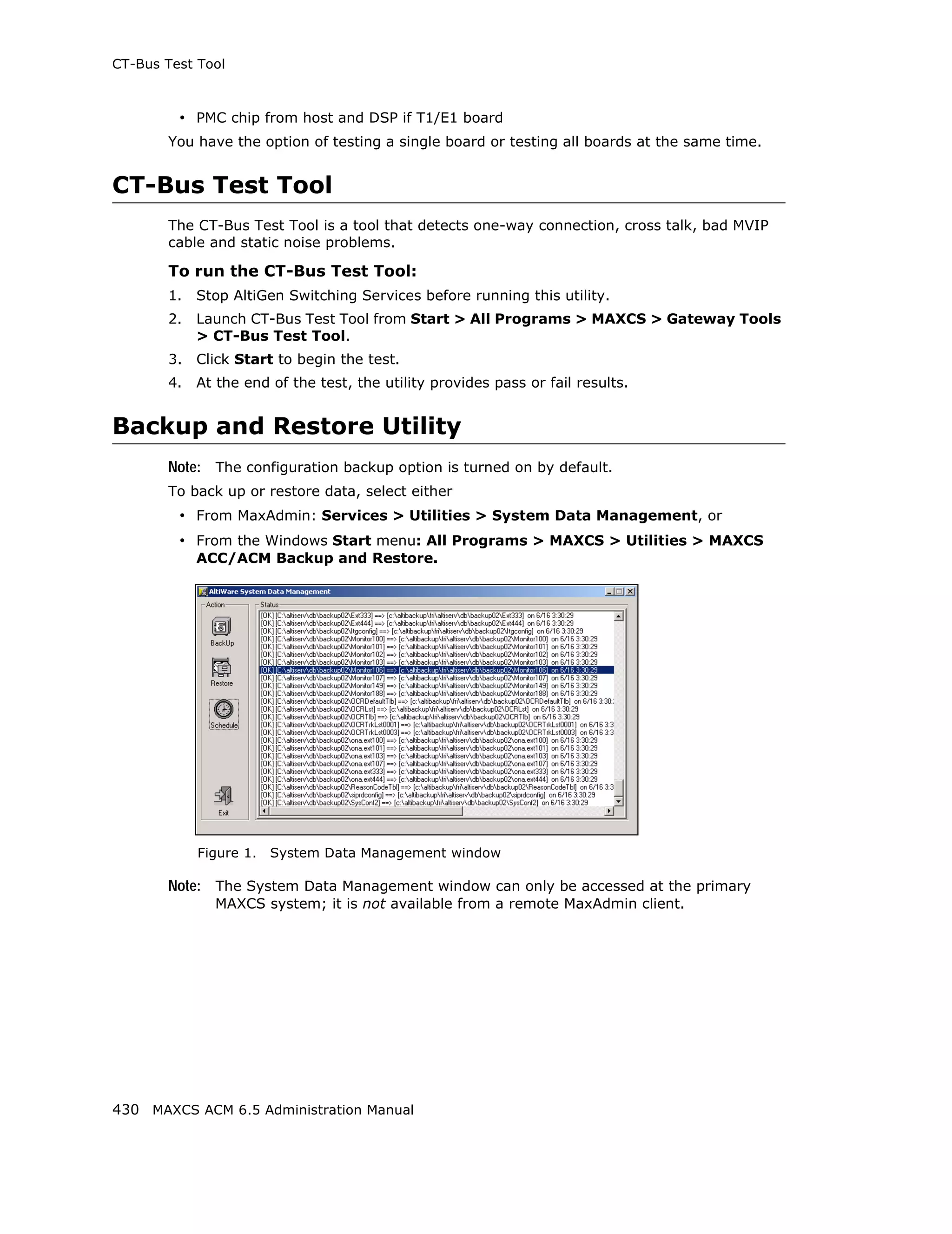
Adding and Attaching a Gateway
Caution! Always try to attach a gateway when call activity in the system is low. If
resources are being used in one of the gateways, ongoing calls may be
dropped.
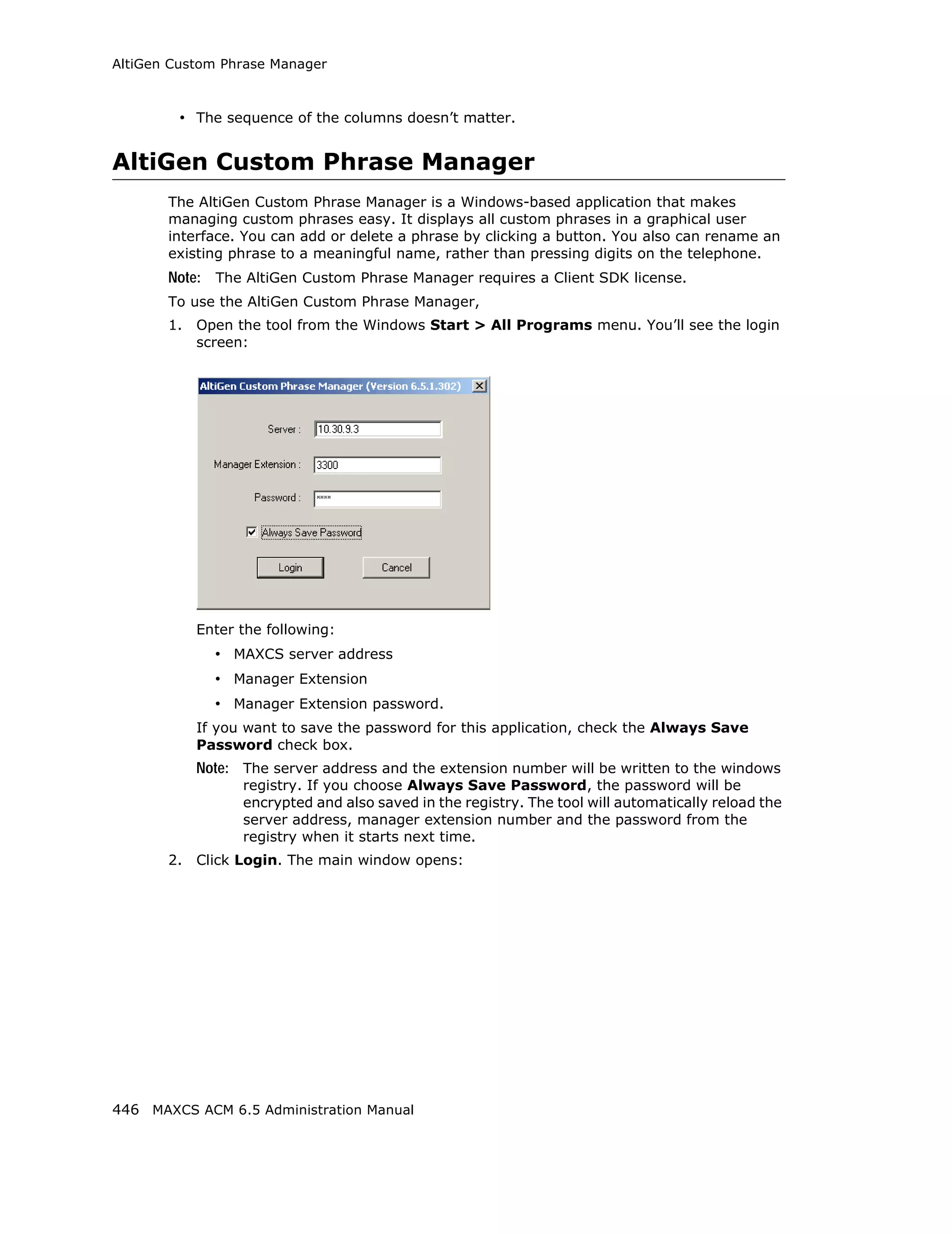
To attach a gateway to the MAXCS system, you must first add it to the list in the
Softswitch Component Configuration window.
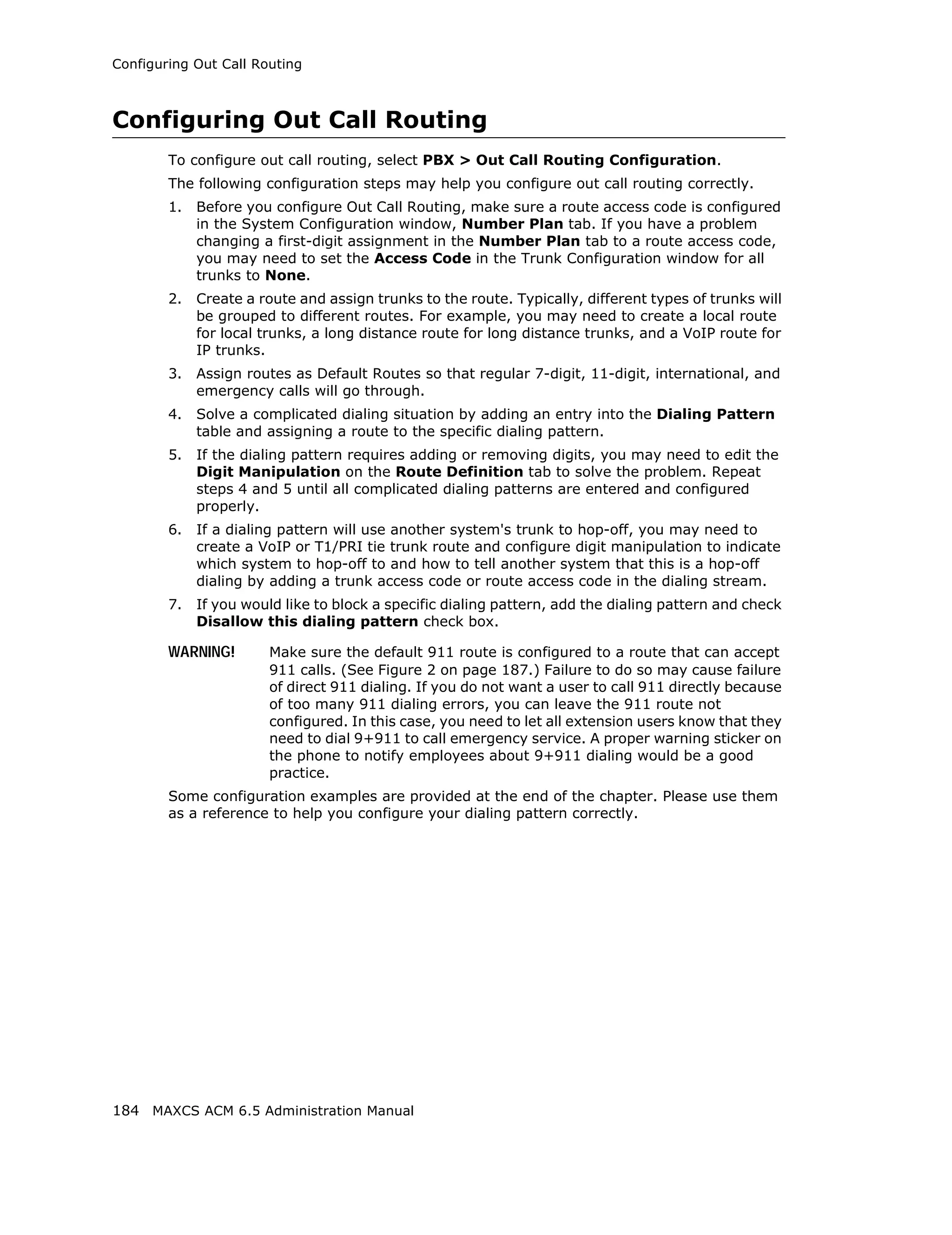
To add a gateway to the list:
1. Click the Add button. The Add Gateway dialog box appears:
MAXCS ACM 6.5 Administration Manual 79](https://image.slidesharecdn.com/maxcsacm6-5administrationmanual-100910152521-phpapp02/75/AltiGen-M-A-X-C-S-A-C-M-6-93-2048.jpg)


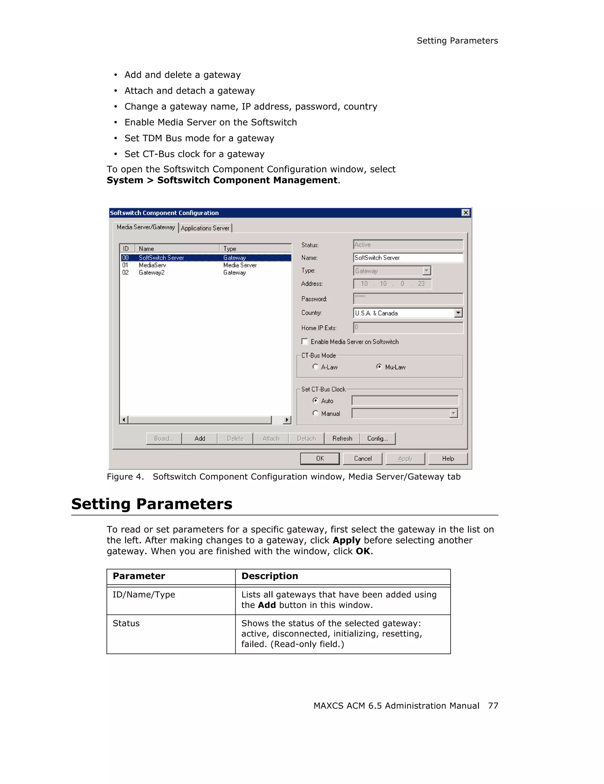
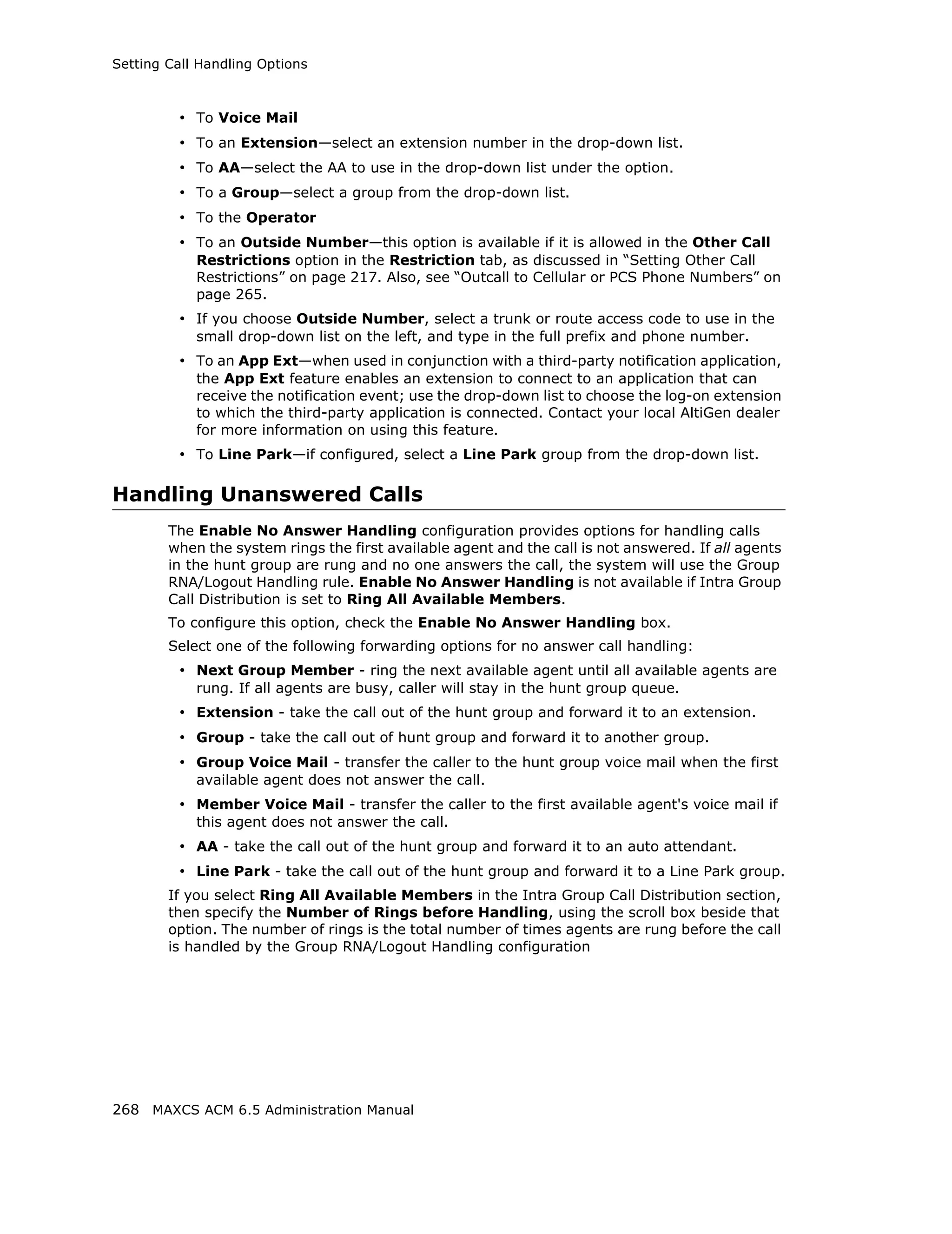
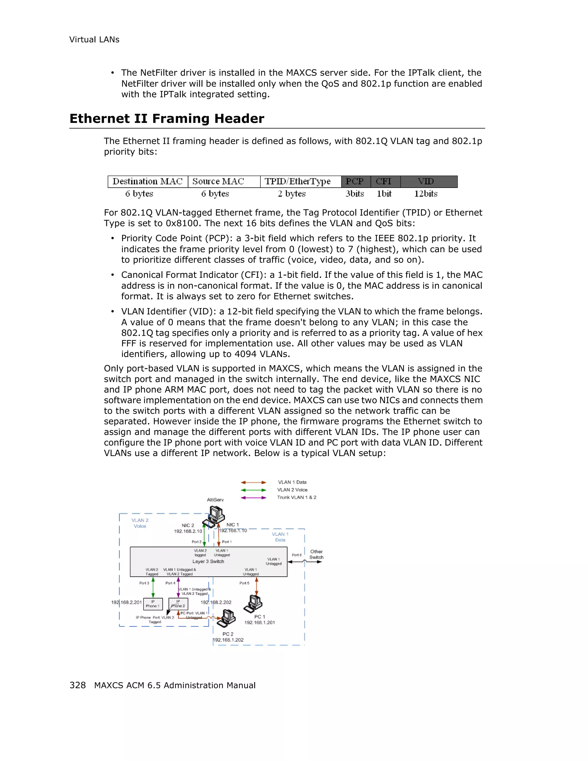
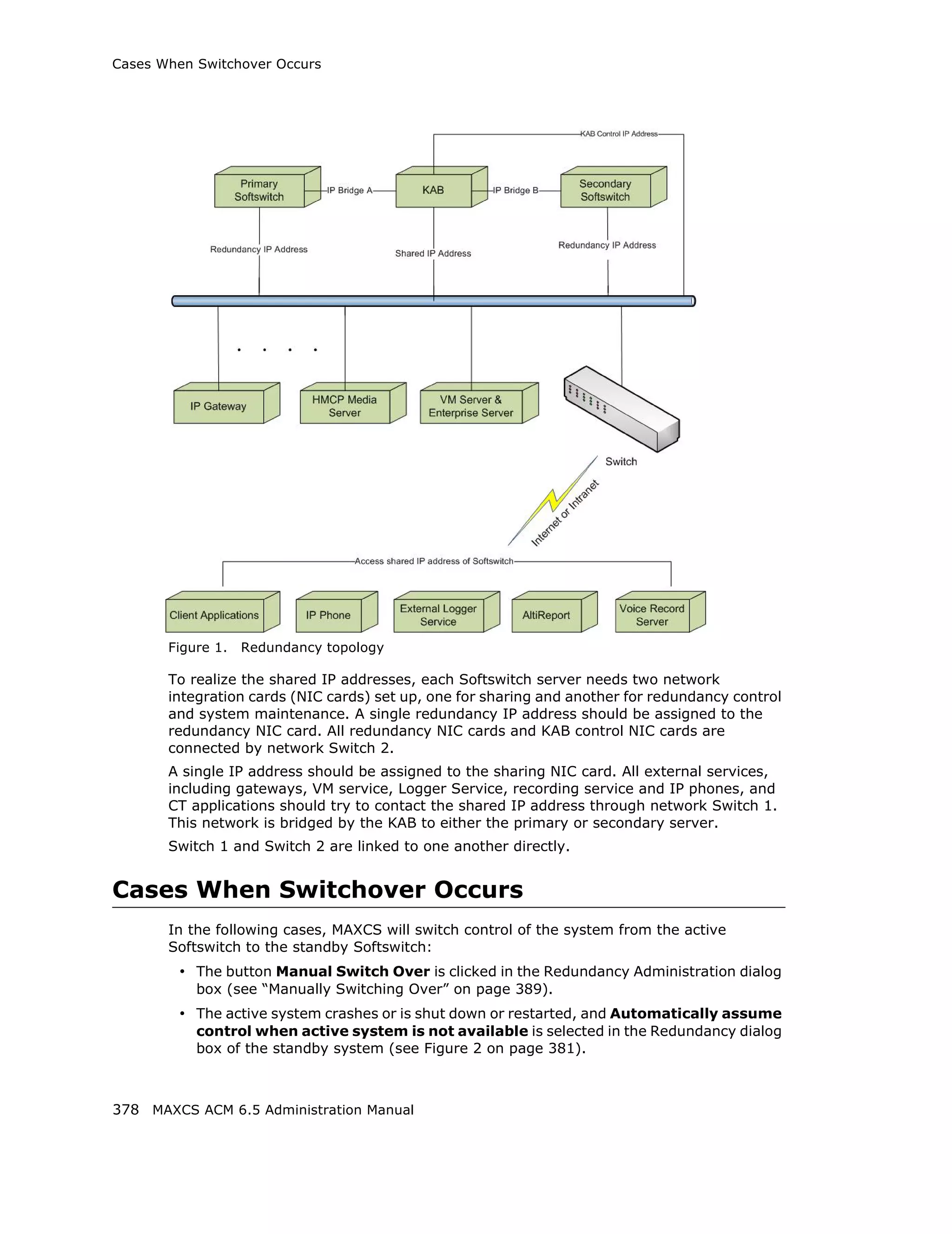
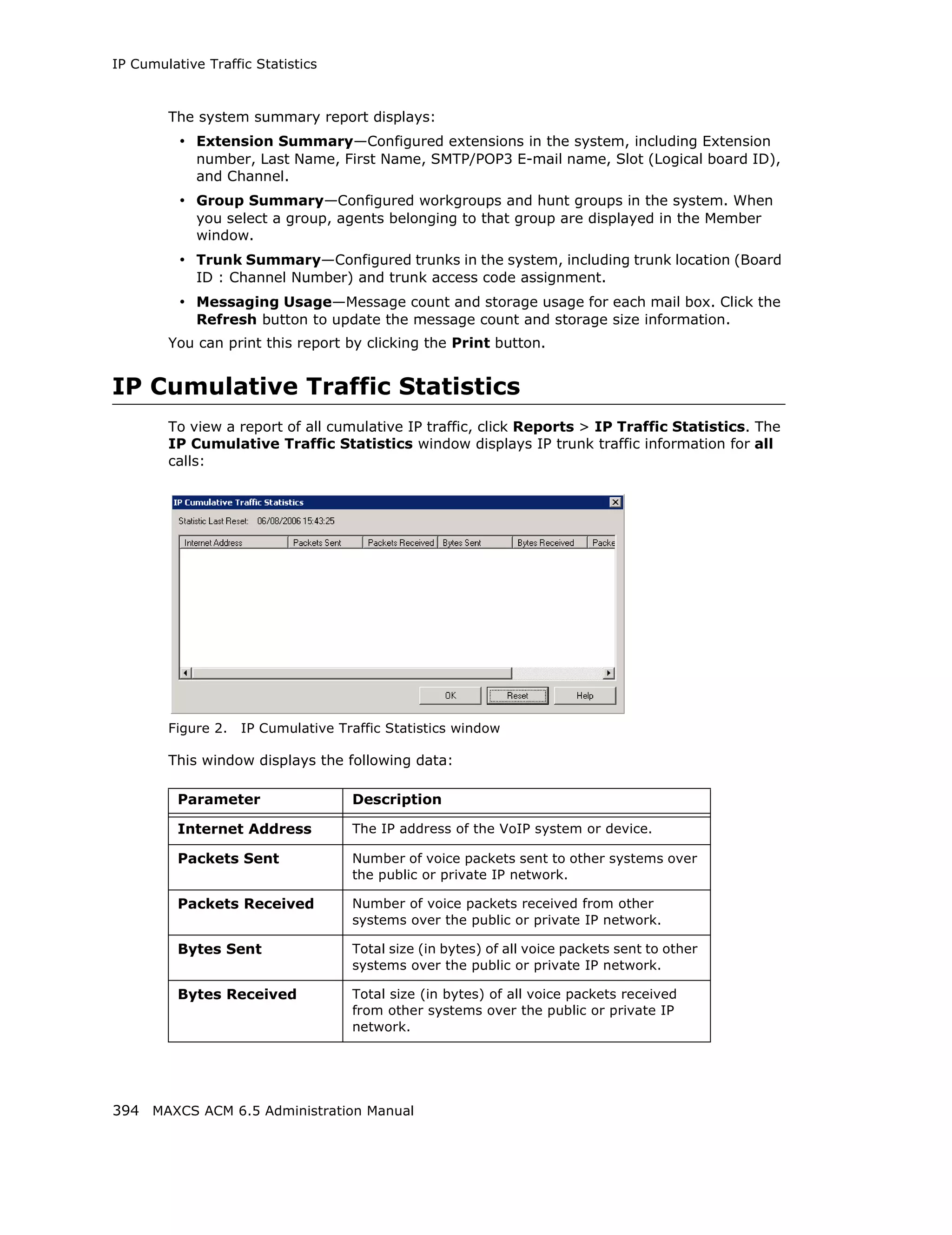
![Setting General Trunk Attributes
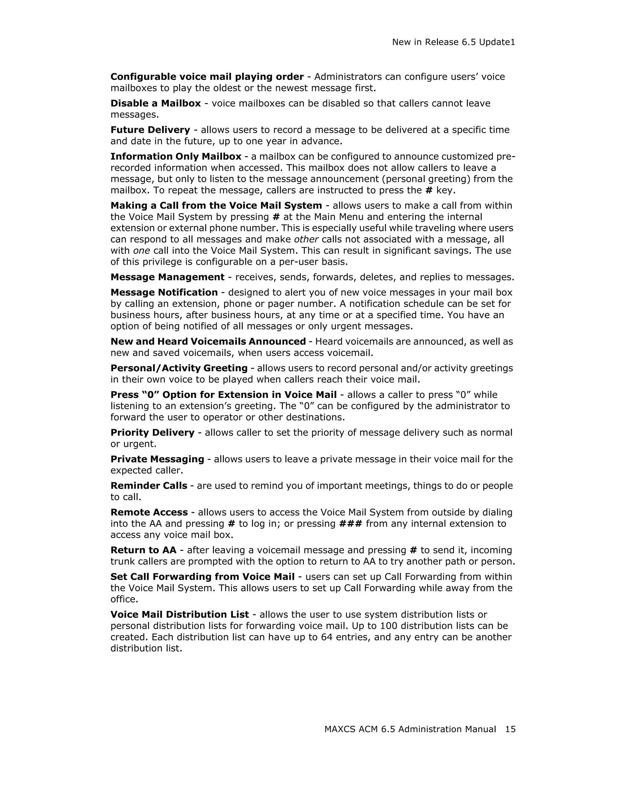
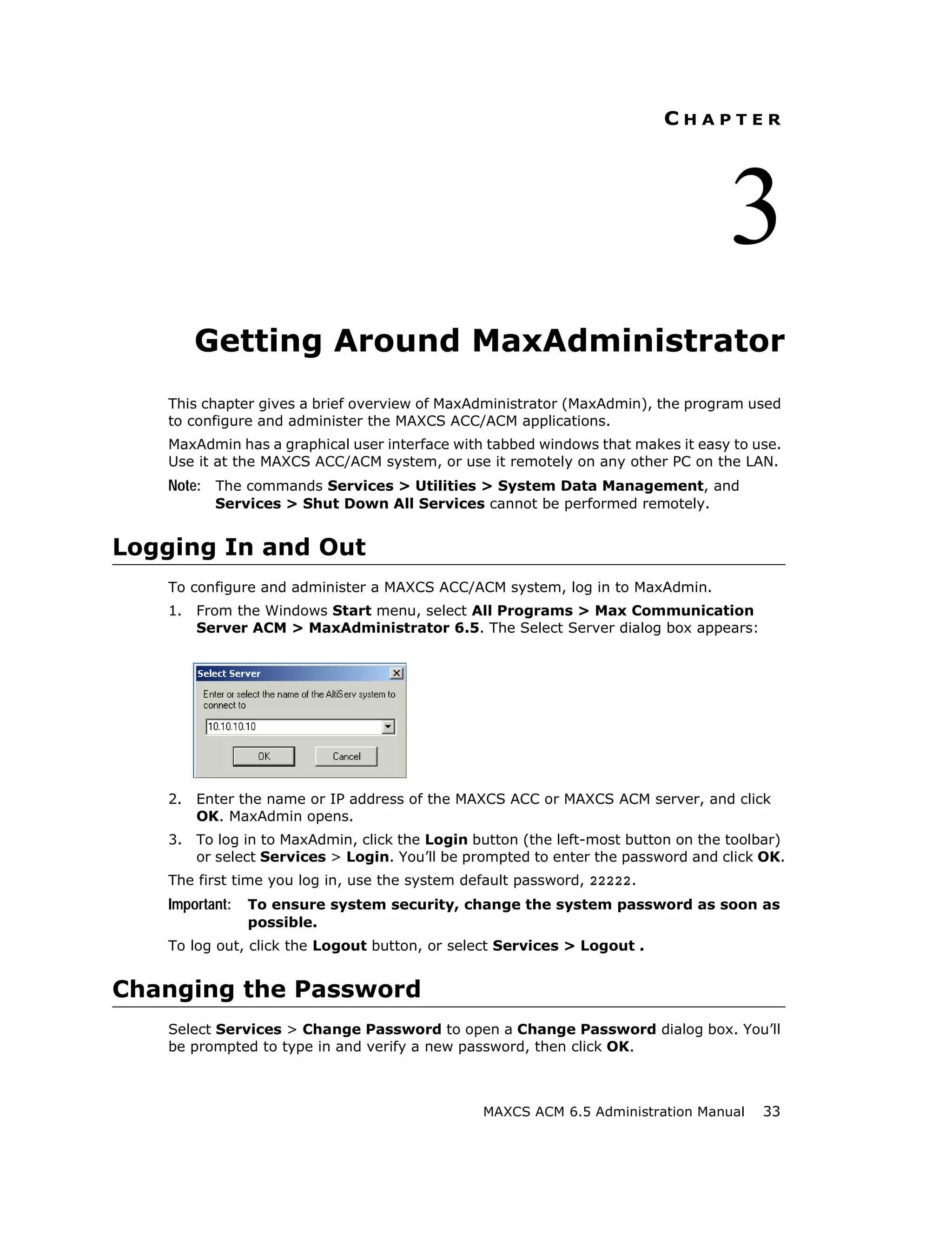
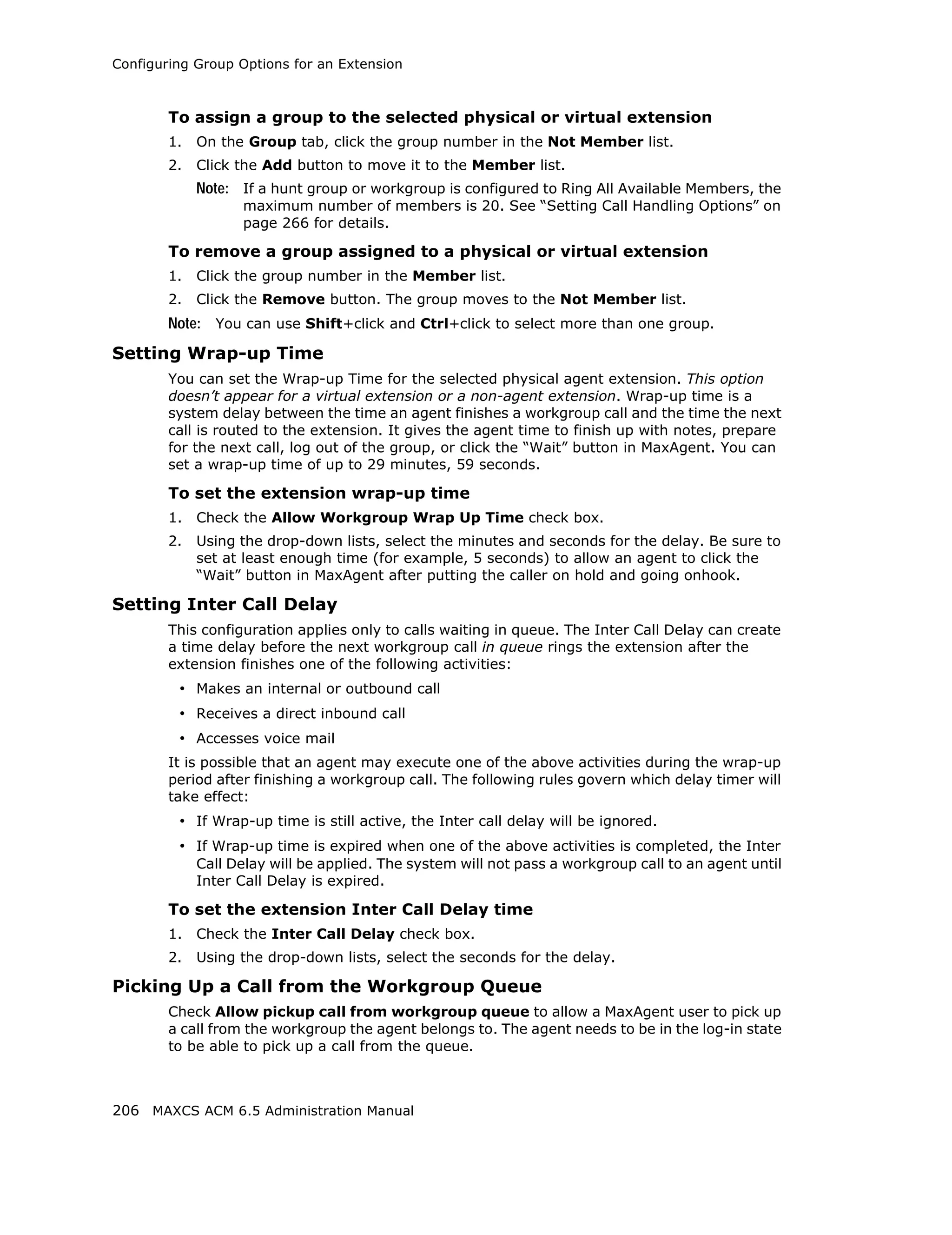
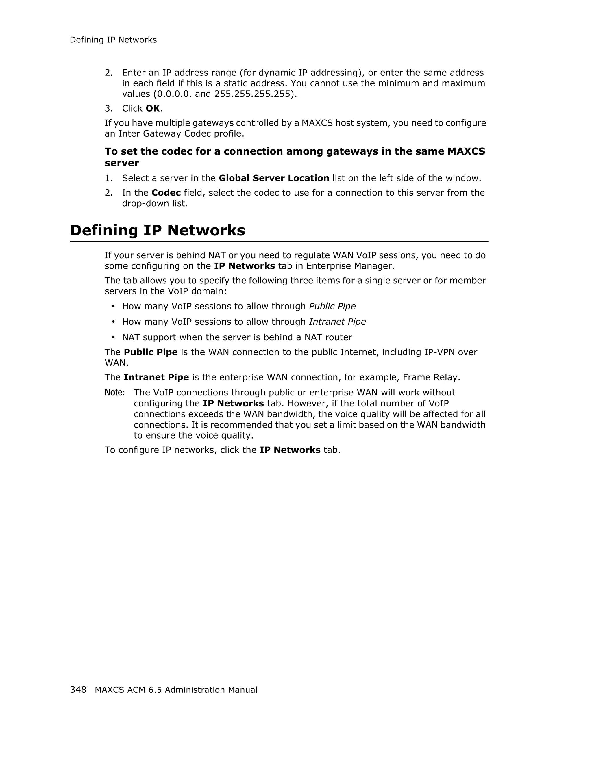
• Overlap - Transmitting dialed DTMF digits to the CO without buffering digits in
the system first. Use Overlap dialing for analog and T1-CAS trunks for best
results. Calls will be completed faster.
• En-bloc - The system will buffer all dialed digits and send it to the CO at once.
Typically is used in ISDN-PRI trunk and SIP trunk.
Note: For IP tie trunks, use the IP Dialing Table in Enterprise Manager to set the
dialing scheme (Enterprise Manager is available by selecting VoIP >
Enterprise Network Management, or from the Windows Start menu).
• Trunk Call Predial String—To have the system automatically insert the configured
digits whenever the selected trunk is used for outgoing calls. This feature is used to
prevent having to dial “9” twice for trunk access when the system is used behind
another PBX system or this trunk is a Centrex line, which requires dialing “9” to make
a call. If you select this option, type the predial digit(s) into the text box.
• Enable Centrex Transfer—When checked, the system is able to transfer an
incoming call to another outside number through the same trunk and release the
incoming trunk. Before you configure this option for the trunk, please make sure
your trunk is a Centrex line or supports the Release Line Transfer (RLT) feature.
Depending on the type of trunk, your configuration may be different:
• If this is an analog Centrex line, you only need to check the Enable Centrex
Transfer check box. A FLASH signal will be transmitted to the CO if the
incoming trunk call needs to be transferred to an outside number.
• If this is a T1-CAS trunk, you may need to add “transfer predial string.” From
the CO point of view, it is their feature code to initiate RLT. Please check with
your carrier to get the specification.
• If this is a PRI trunk, you need to ask your carrier if they support RLT through
DTMF. Some carriers accept *8 to signal RLT. AltiGen PRI trunks currently do
not support 2-B channel transfer feature.
How to signal MAXCS that it is a Centrex transfer:
• If a call is connected to an extension, the extension user needs to dial
FLASH * plus trunk access code and the outside number.
• If a virtual extension forwarding or speed dialing number is configured to an
outside number and the extension user transfers a call to the virtual extension
or speed dialing number, the system will add the Centrex FLASH automatically.
You don’t need to add the “*” in the forwarding or speed dialing digit stream.
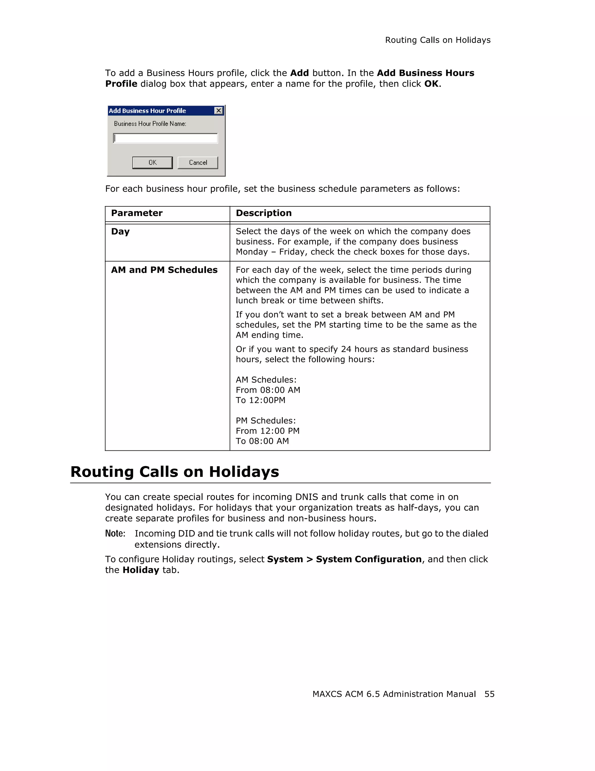
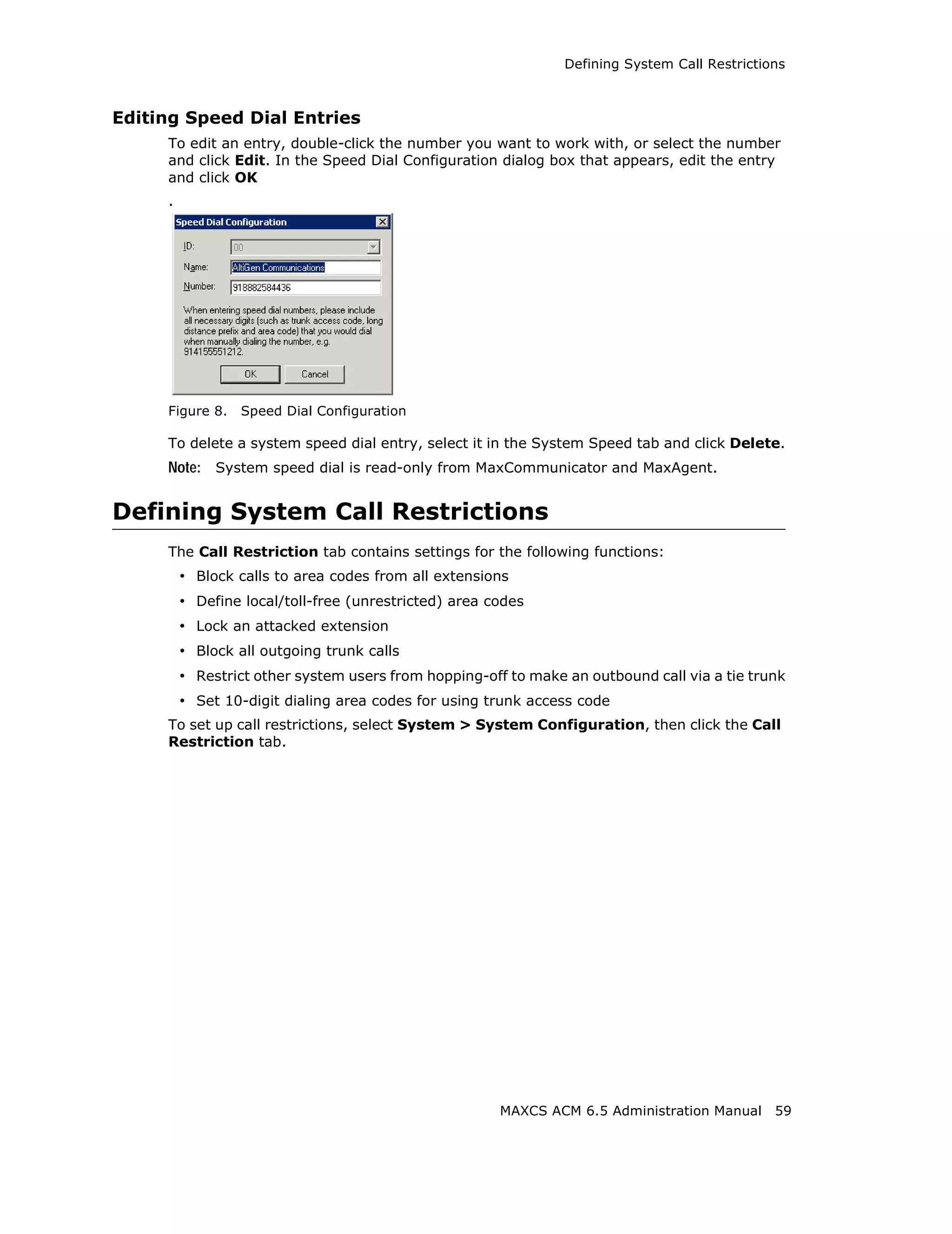
• Attribute—In Service makes the trunk available for use. Out of Service prevents
the trunk from being used (for example, while performing maintenance).
• Enable Tie Trunk—This configuration field is meaningful only if you use T1 or PRI
to connect two MAXCS systems back-to-back. Do not check this box if you connect
a MAXCS to a third-party PBX via T1 or PRI trunk.
When this configuration is checked, the system software will interpret the incoming
[ANI] [DNIS] digit sequence as [Caller’s Extension Number] and [Target Extension
Number]. An incoming tie trunk call will be routed to the target extension and all the
Incall Routing rules will be bypassed. If you do not check this box for system-to-
system tie trunk, the system will check the Ext. DID/DNIS Routing/Caller ID Routing
table first. If there is no match, the trunk incall routing rule will apply.
Note: The Enable Tie Trunk field under Board Configuration > Protocol needs
to be enabled for T1/PRI tie trunks as well. It will tell the system to transmit
[Caller’s Extension Number] and [Target’s Extension Number] as [ANI]
[DNIS] to the other system. In case this is a T1-CAS, which typically cannot
126 MAXCS ACM 6.5 Administration Manual](https://image.slidesharecdn.com/maxcsacm6-5administrationmanual-100910152521-phpapp02/75/AltiGen-M-A-X-C-S-A-C-M-6-140-2048.jpg)
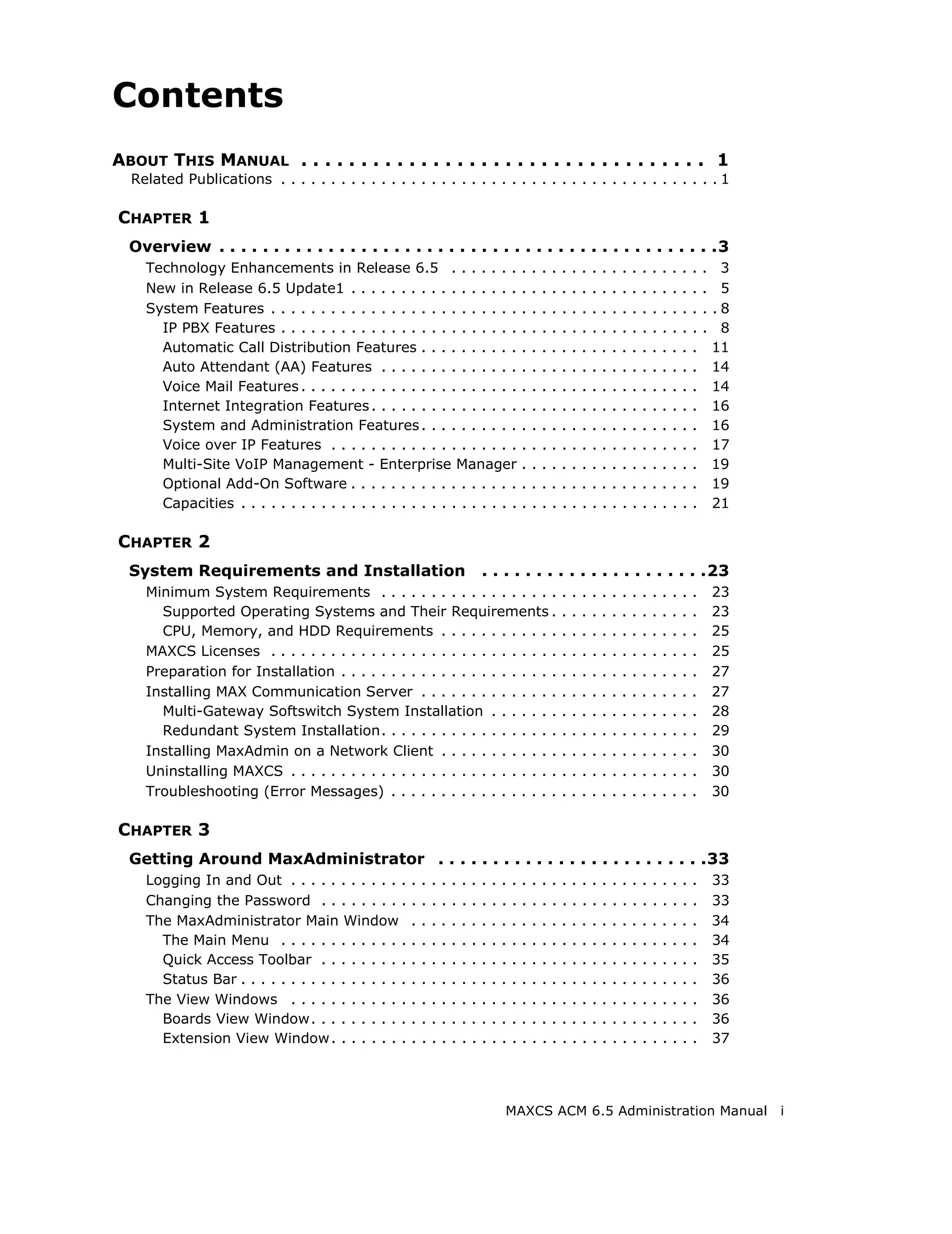
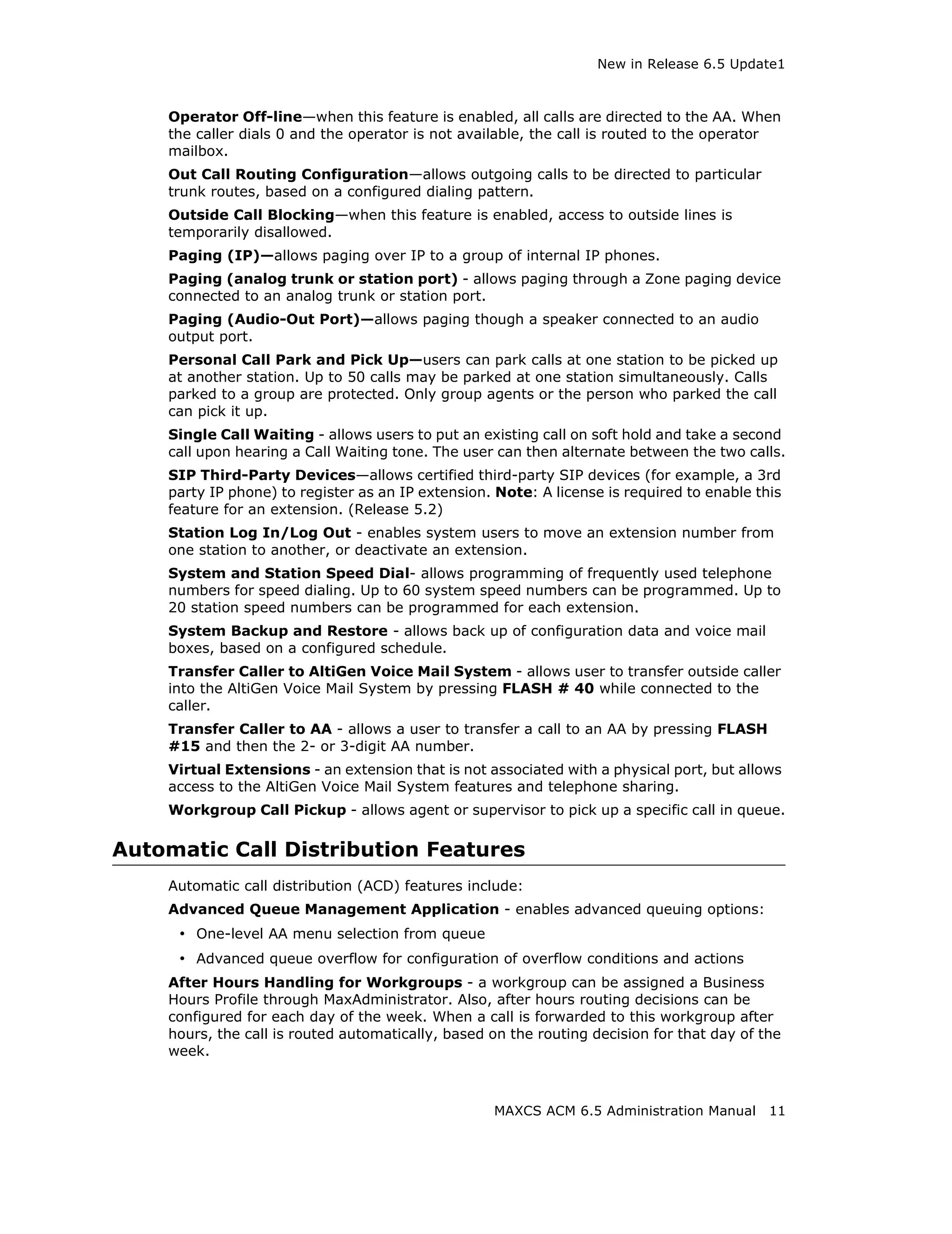
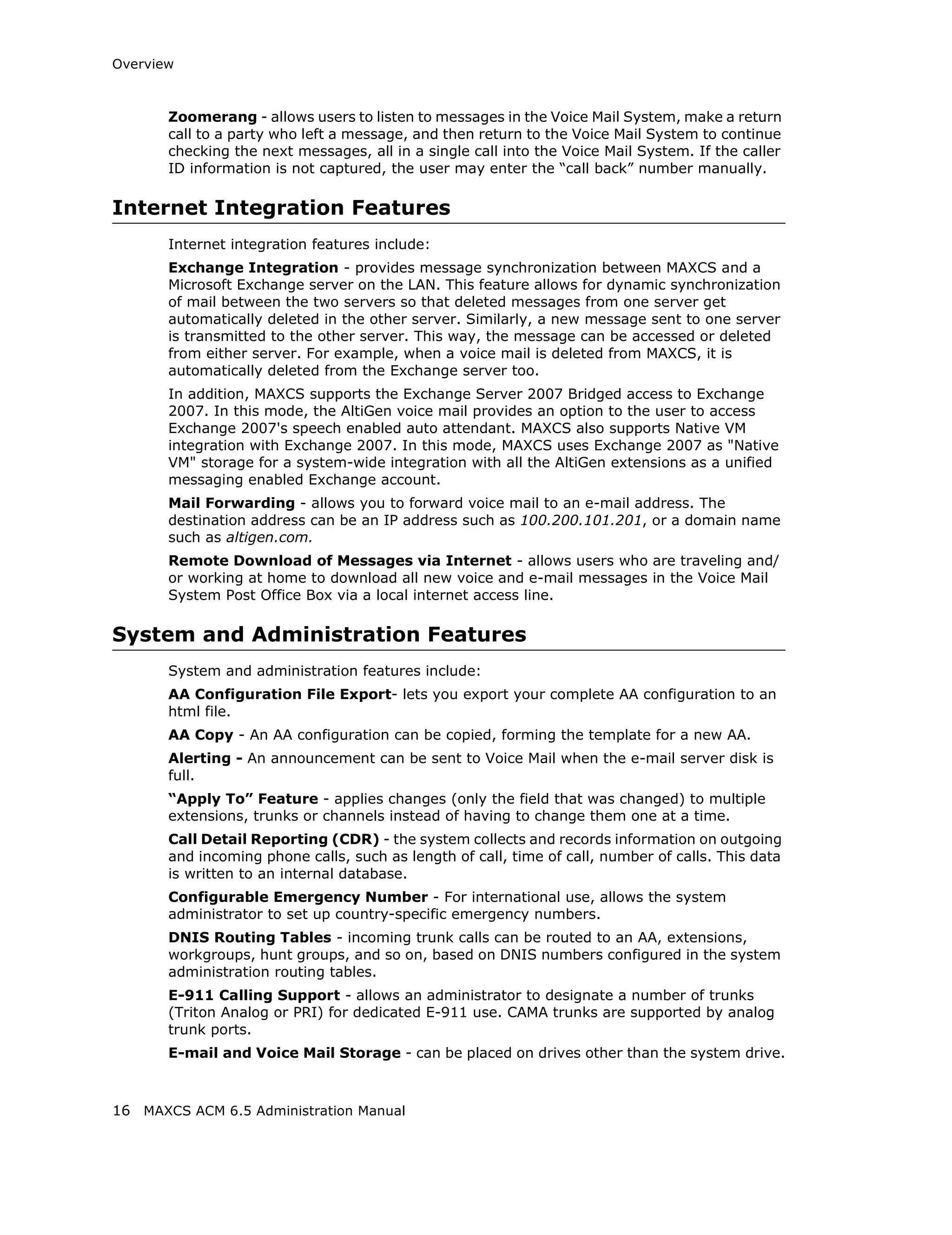
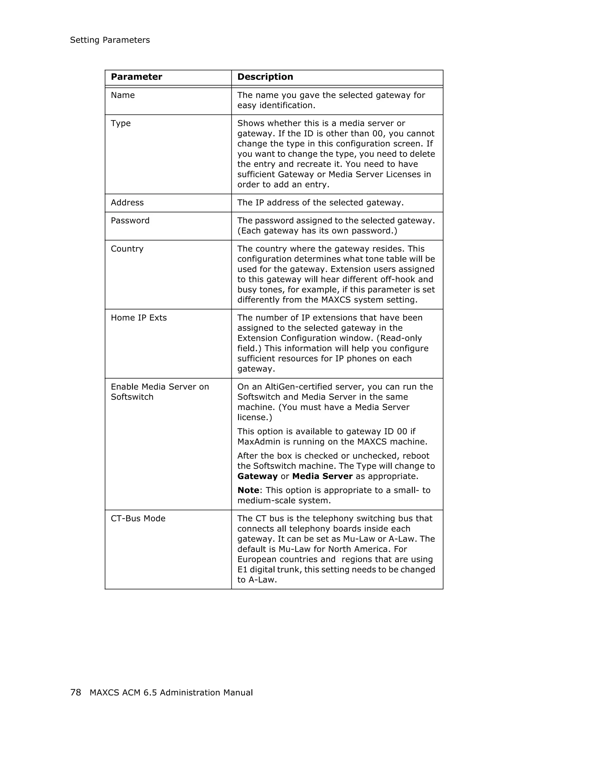
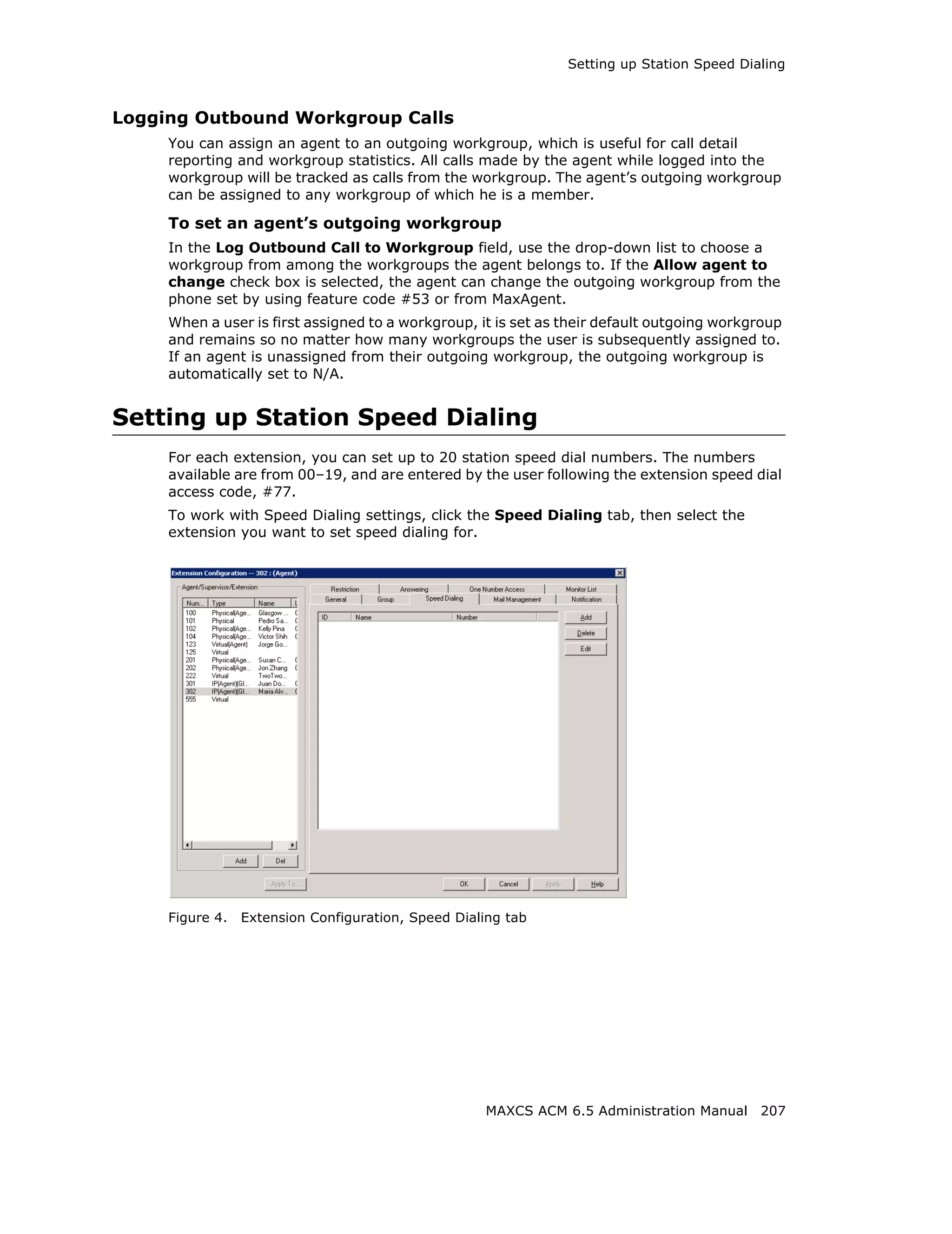
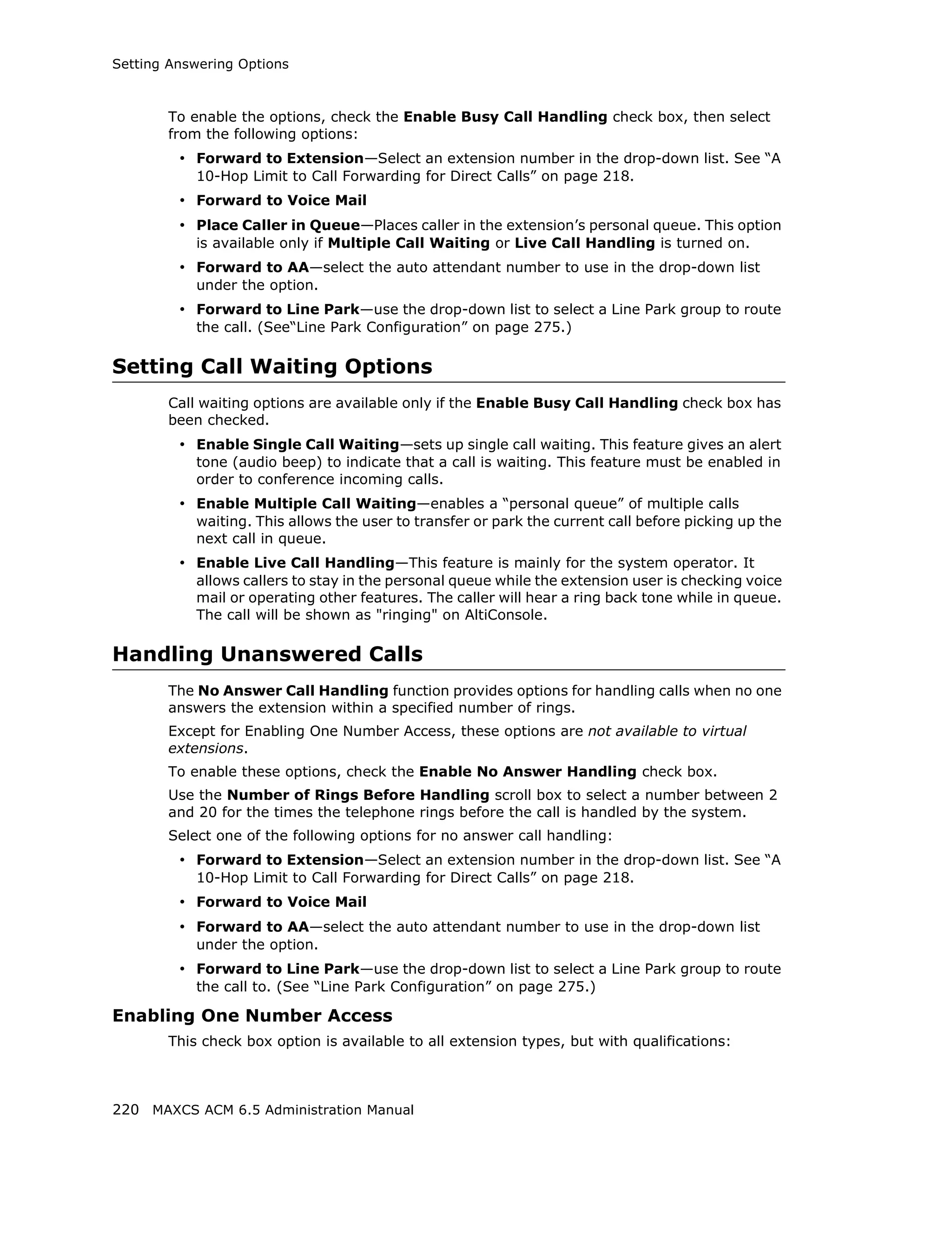
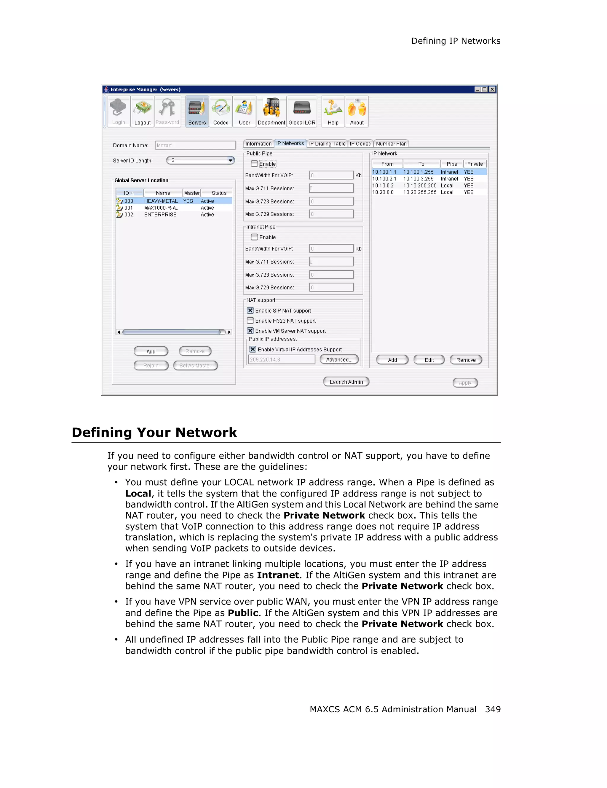
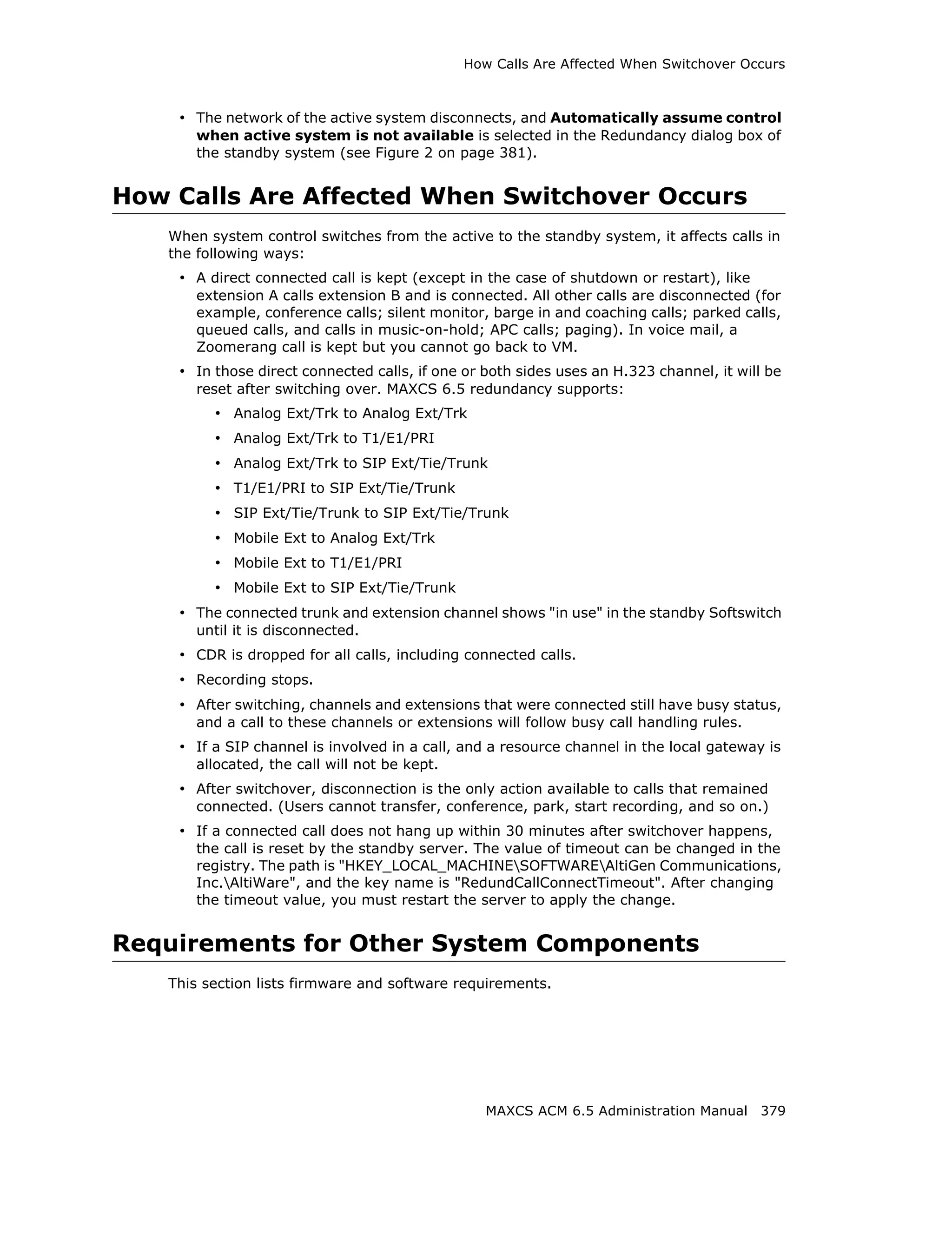
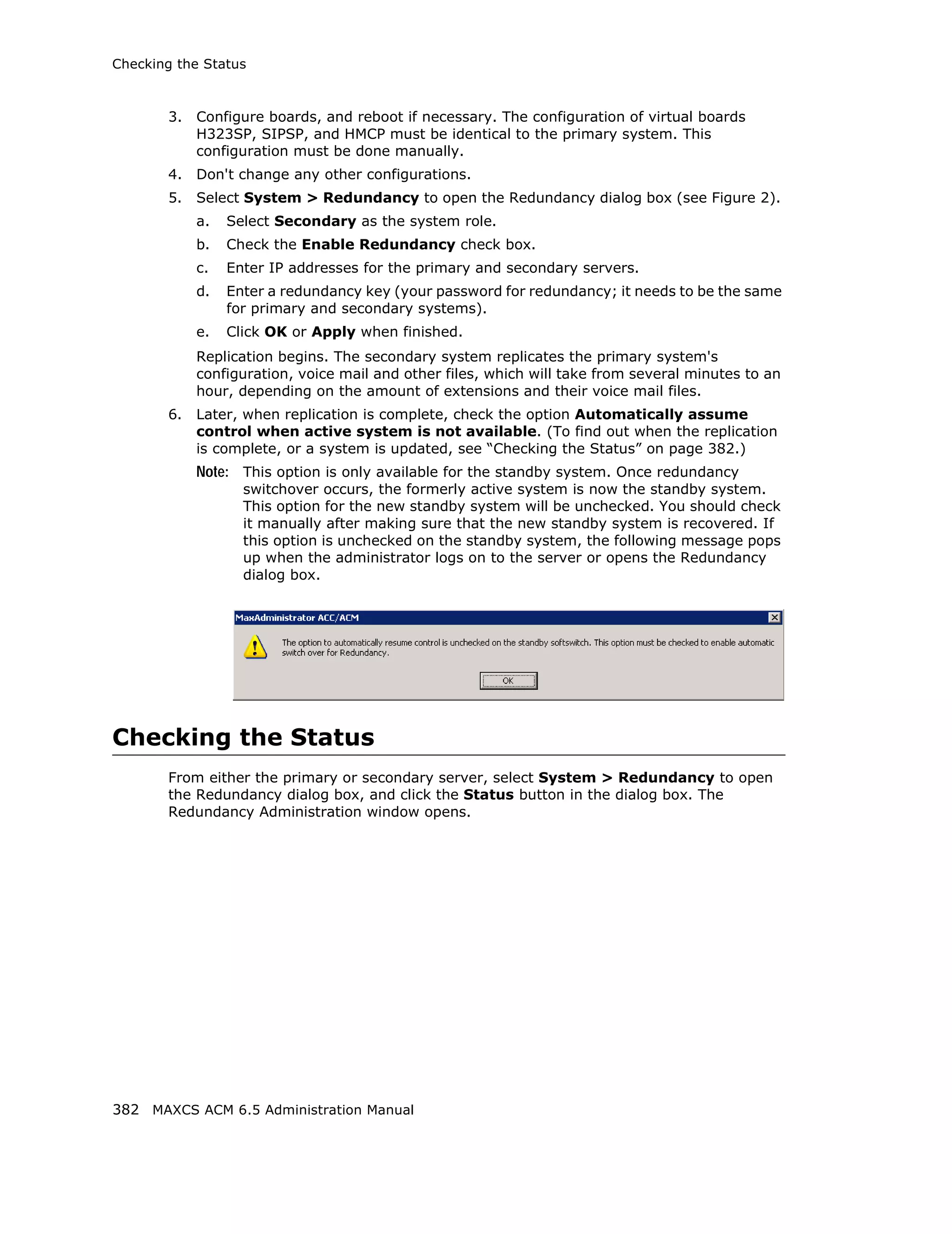
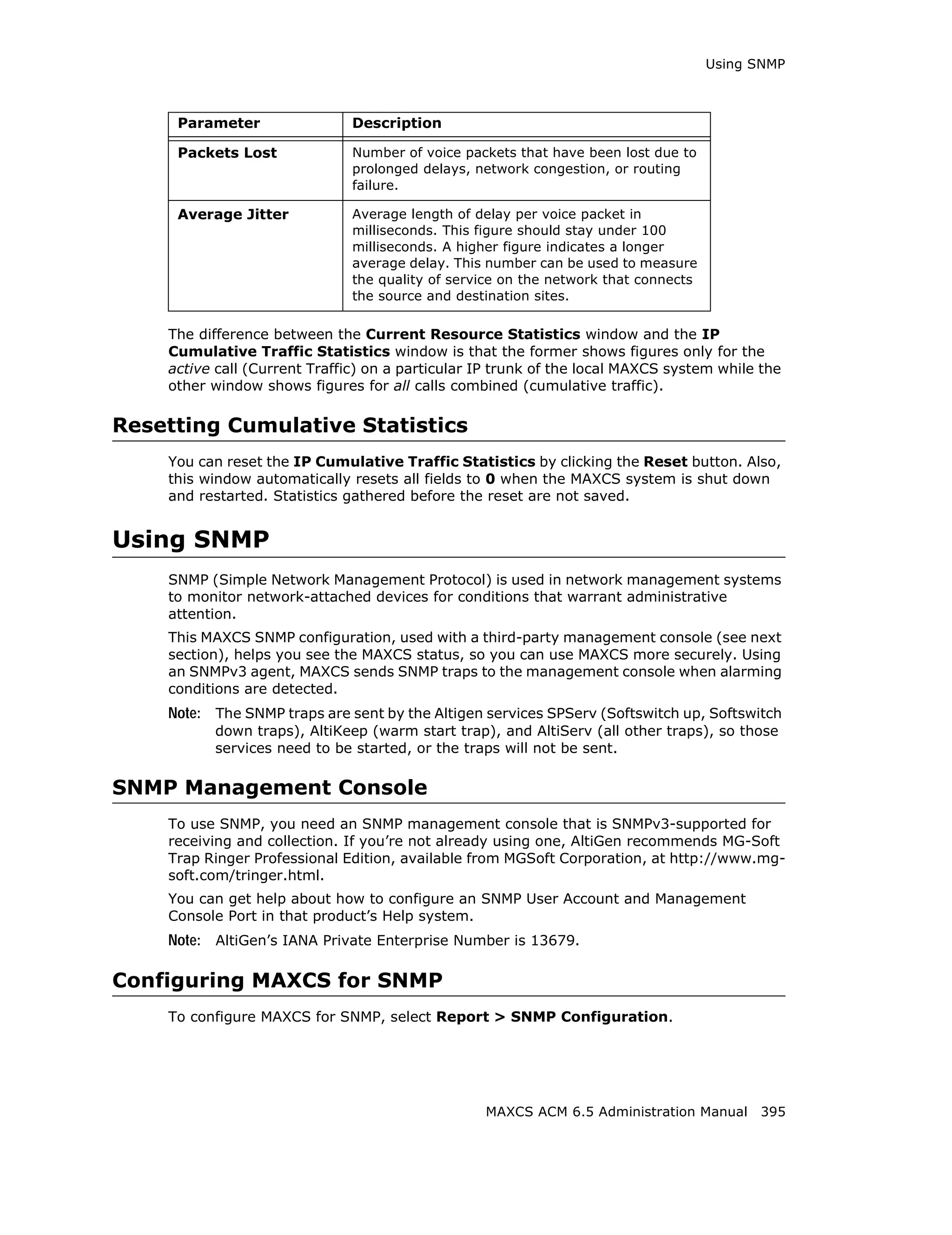
![Setting General Trunk Attributes
transmit any data to the CO, the system will use DTMF as a way to transmit
[Caller’s Extension Number] and [Target’s Extension Number] to the other
side of the tie trunk. Because the format is AltiGen proprietary, you may have
a problem if you enable this configuration when connecting to a non-AltiGen
PBX.
• Holiday Profile—A holiday profile can be assigned to a trunk. The drop-down list
selection is based on settings configured in the Holiday tab of System Configuration
(see “Routing Calls on Holidays” on page 55).
• Business Hour Profile—A business hour profile can be assigned to a trunk. The
drop-down list selection is based on settings configured in the Business Hours tab
of System Configuration.
• Recording Option—Recording for incoming and outgoing calls is supported for
Triton Analog, T1/E1, and IP trunks; use the drop-down list to select Disable or
Enable. If you select Enable, choose the license you want to assign (Concurrent
Session or Dedicated Seat), and make sure that in System > Recording
Configuration one of the trunk-based recording options is selected.
Note: When you use trunk-based recording, inbound or outbound calls are recorded
as long as the trunk is in use. For example, an inbound call that is answered
by an AA, routed to an operator, and transferred to an extension will begin
recording when the AA answers the call and end recording when the trunk is
released.
With extension recording, recording starts only when the extension user
answers the call.
• Trunk Properties—Opens a dialog box that allows you to configure low-level,
hardware-specific properties for each trunk. The options vary depending on the type
of board and trunk; this is discussed in subsequent sections.
MAXCS ACM 6.5 Administration Manual 127](https://image.slidesharecdn.com/maxcsacm6-5administrationmanual-100910152521-phpapp02/75/AltiGen-M-A-X-C-S-A-C-M-6-141-2048.jpg)
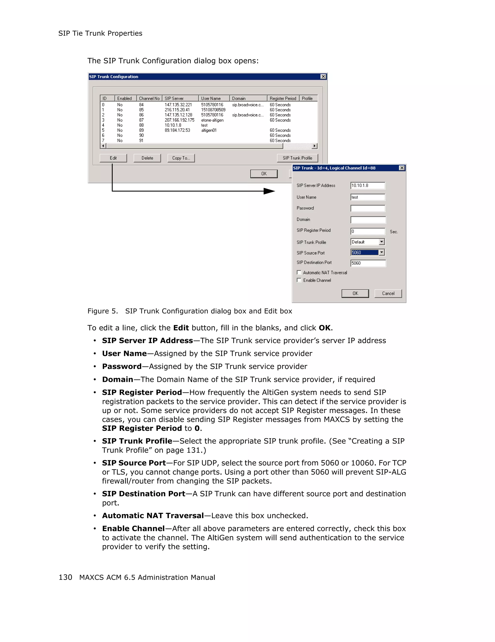
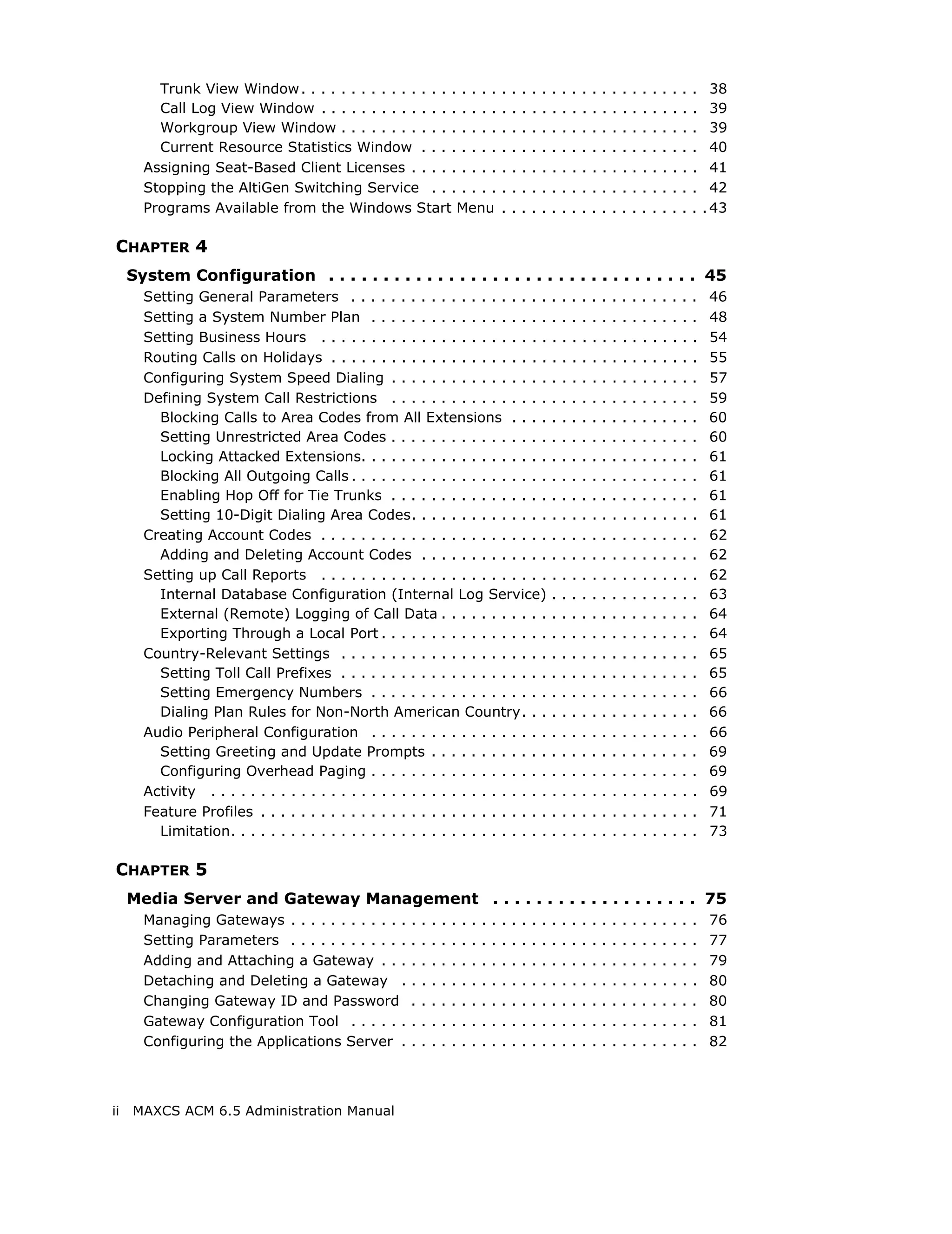
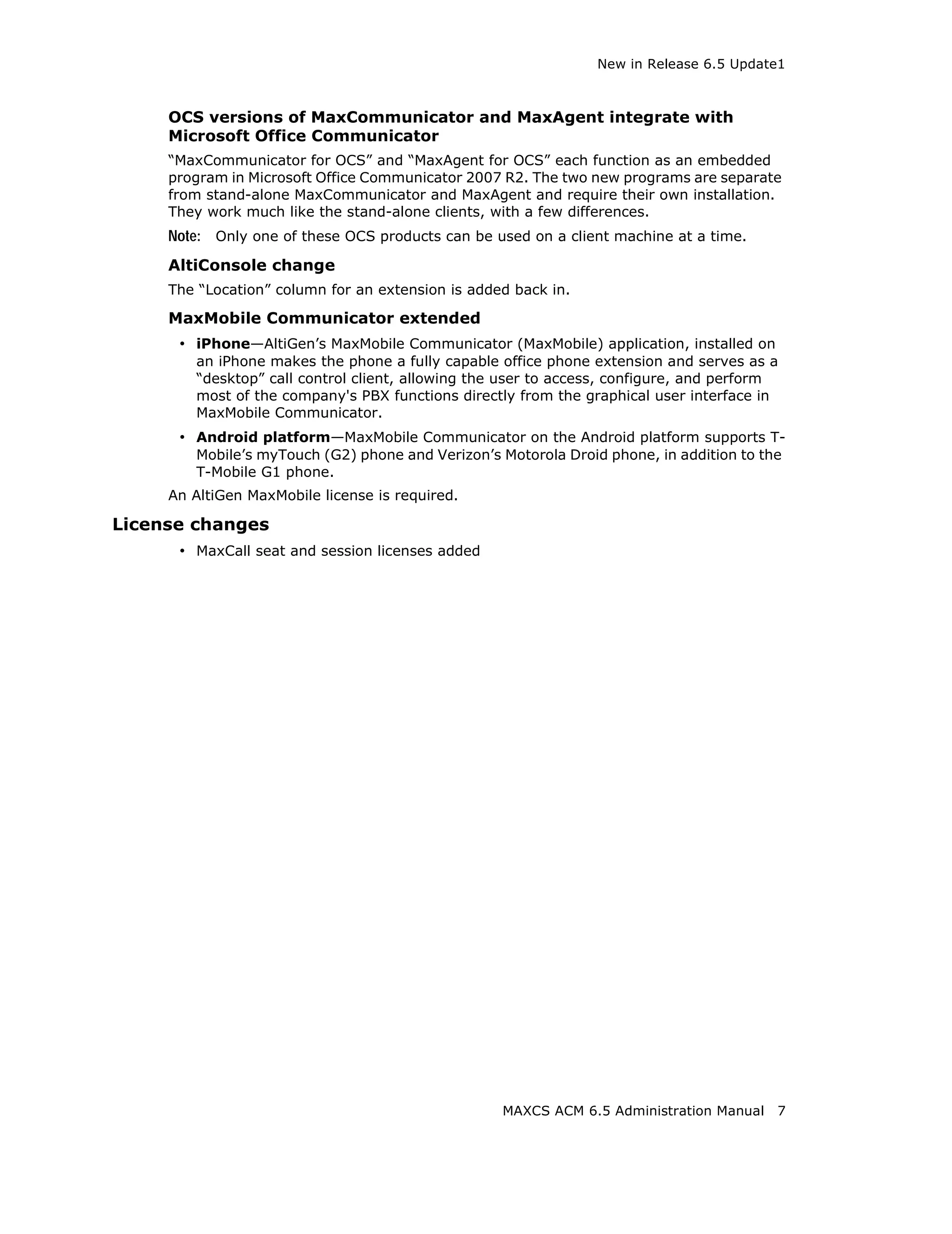
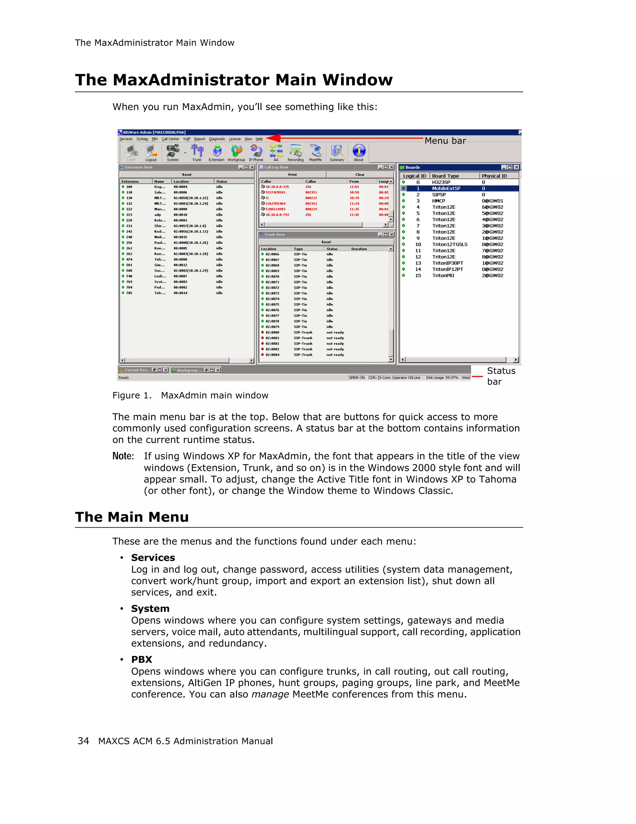
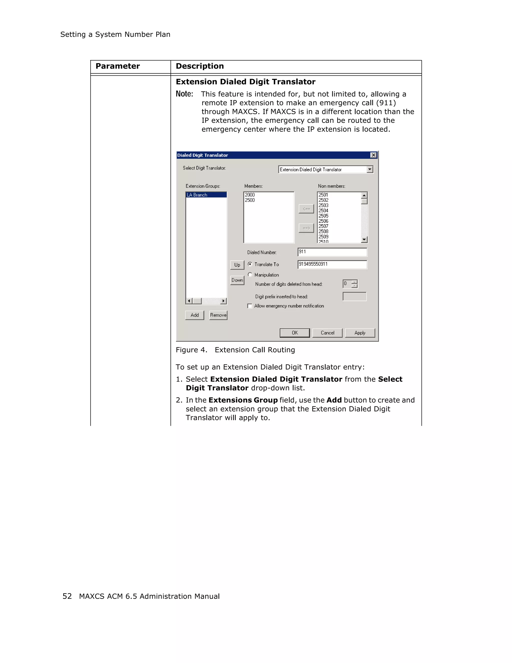
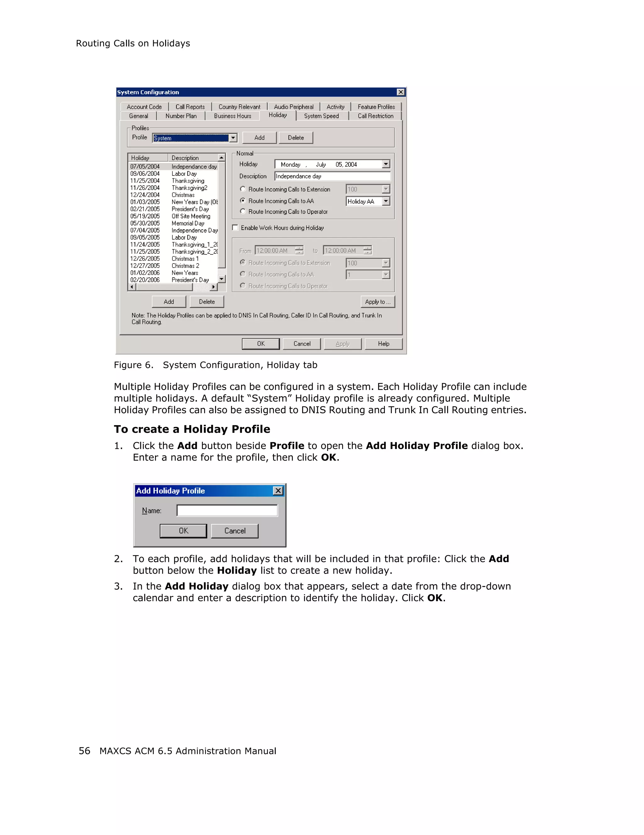
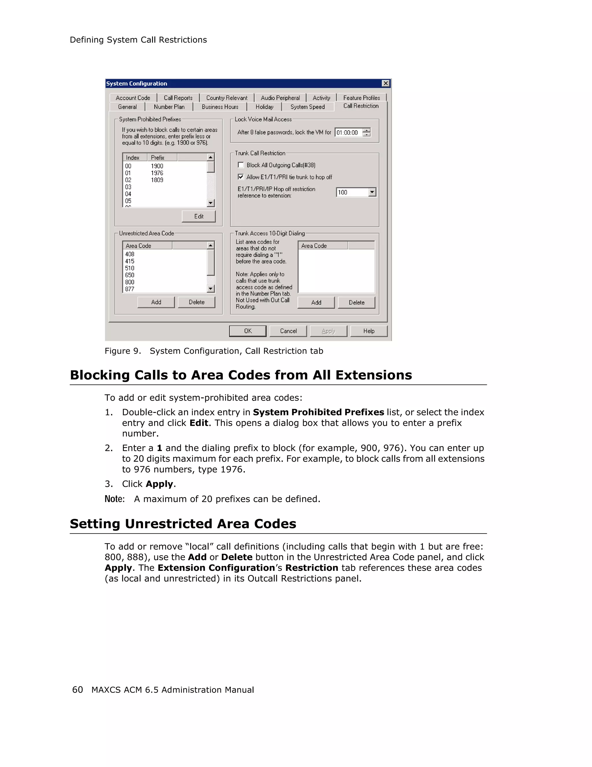
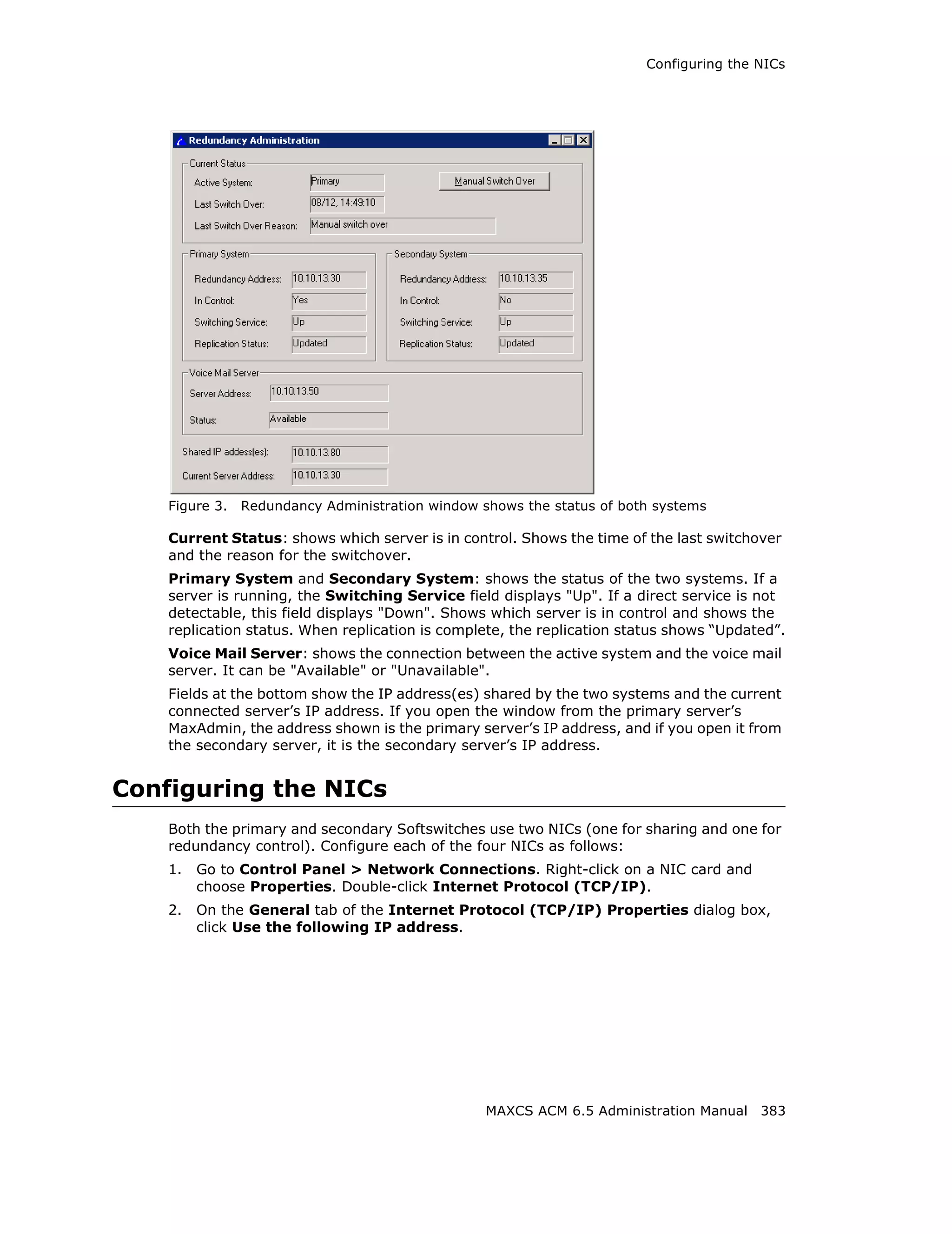
![SIP Tie Trunk Properties
Field Description
Carrier can only Enter the number of digits, then enter a calling number in the
accept Calling field below the table in case the carrier cannot accept
Number with configured numbers.
minimum x digits
Carrier can only If you select the this option, specify “assigned numbers” by
accept assigned clicking the Add button and entering the numbers. To edit or
numbers as Calling delete a number you added, select it and click the Edit or Del
Number button. Enter a calling number in the field below the table in
case the carrier cannot accept configured numbers.
Send Caller Name Check to also send the caller name to callees.
Enable Standard Check this box if the SIP service provider uses SIP Record-
Record-Route Header Route and the SIP trunk cannot make or receive calls. If it
already works, DO NOT CHECK or UNCHECK this box. [Service
provider Bandwidth.com with Edgewater Route require this
checked]
Incoming DID When a call comes in, the SIP trunk uses To Header or
Number Field Request URI as the DID/DNIS number
132 MAXCS ACM 6.5 Administration Manual](https://image.slidesharecdn.com/maxcsacm6-5administrationmanual-100910152521-phpapp02/75/AltiGen-M-A-X-C-S-A-C-M-6-146-2048.jpg)
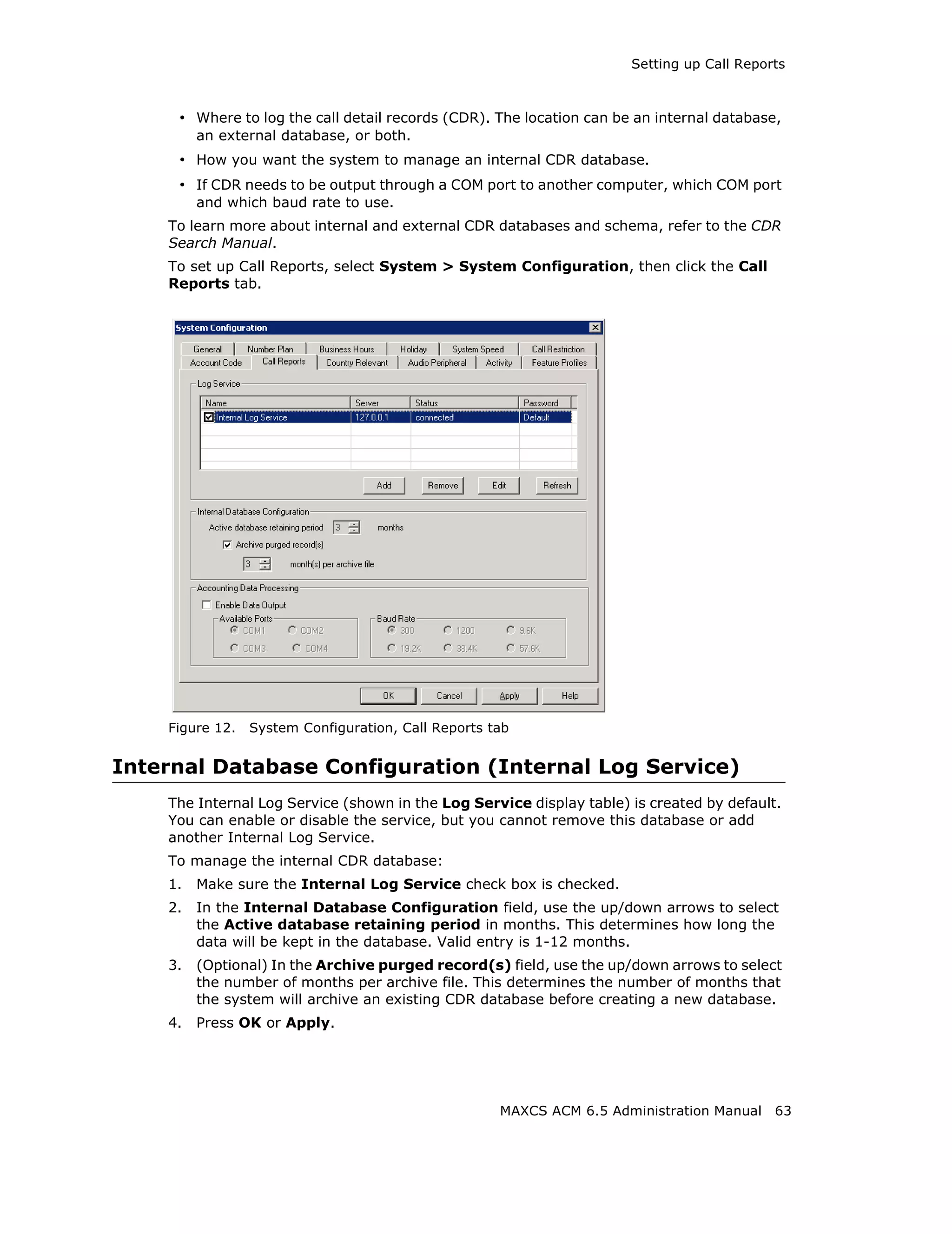
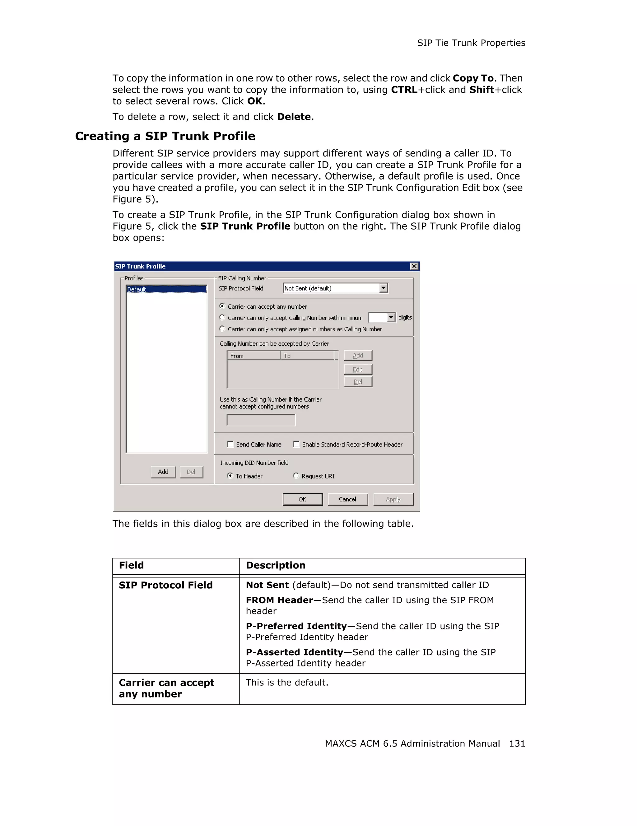
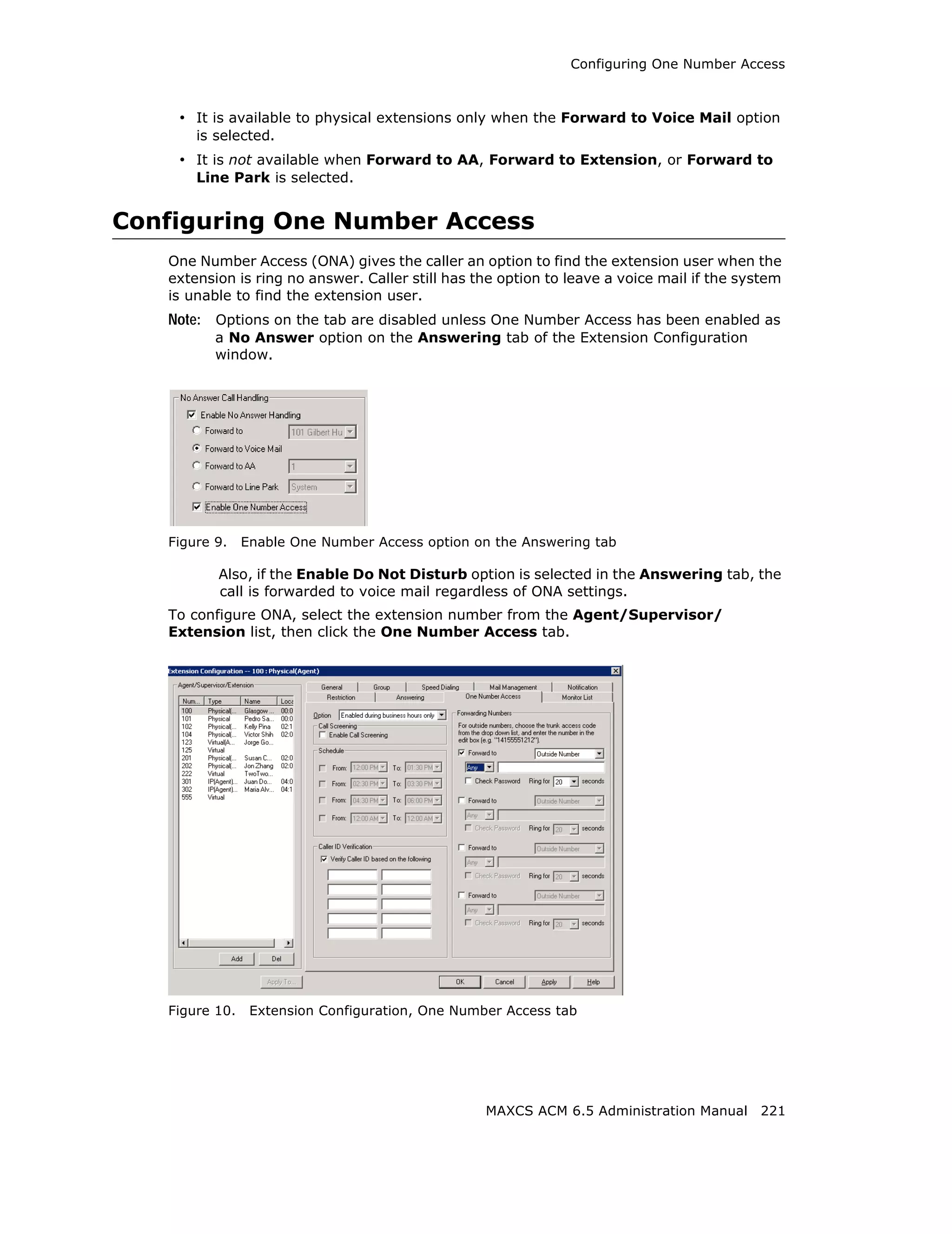
![Configuring the Triton T1/E1 Board
Error Message Meaning Action
L1 failure: <Remote Layer 1 failure, CO Correct the settings.
Alarm Indication notifies that the
(RAI)> configuration is wrong;
RAI = Remote Alarm
Indicator
L1 failure: <No Sync Layer 1 failure, physical Possible span mis-
Frames layer; no valid framing is configuration (ESF is
detected. selected but the actual
framing is SF, or vice
versa). Check span
configuration.
L1 failure: <Red Layer 1 failure, physical Location condition,
Alarm> layer; Bi-Polar Violations equipment problem.
(BPV), Line Code - For excessive BPV/
Violations (LCV), or Out LCV, check AMI/B8ZS
Of Frame detected setting.
- For OOF, check the
MVIP bus master
setting.
OR
Have CO perform a line
test to check for a faulty
cable or line.
[PRI only] Layer 2 failure, data link Check if D-channel is
L2 Failure: <No Sync layer; no sync flag has active or not
Flag> been detected in data
link layer
[PRI only] Layer 2 failure, data link CO must activate HDLC
L2 Failure: <Not layer; the peer-to-peer link
established> link has not established
in data link layer
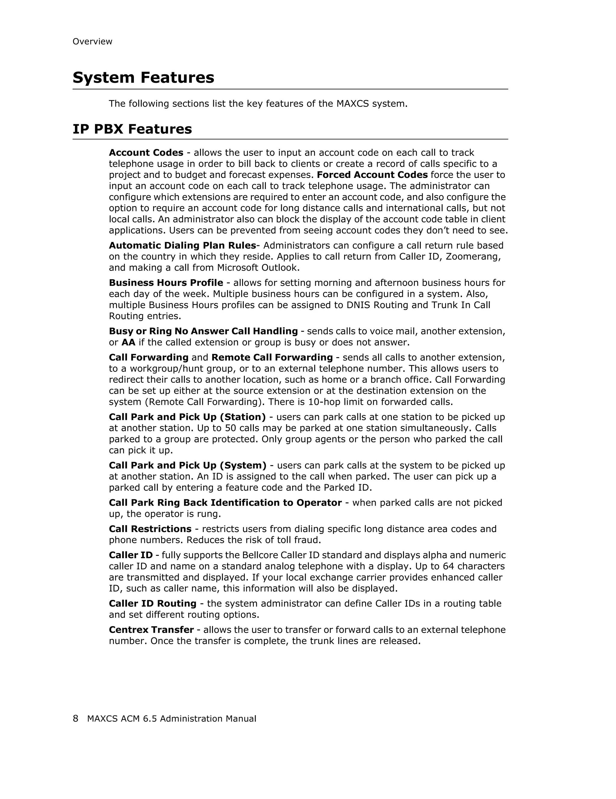
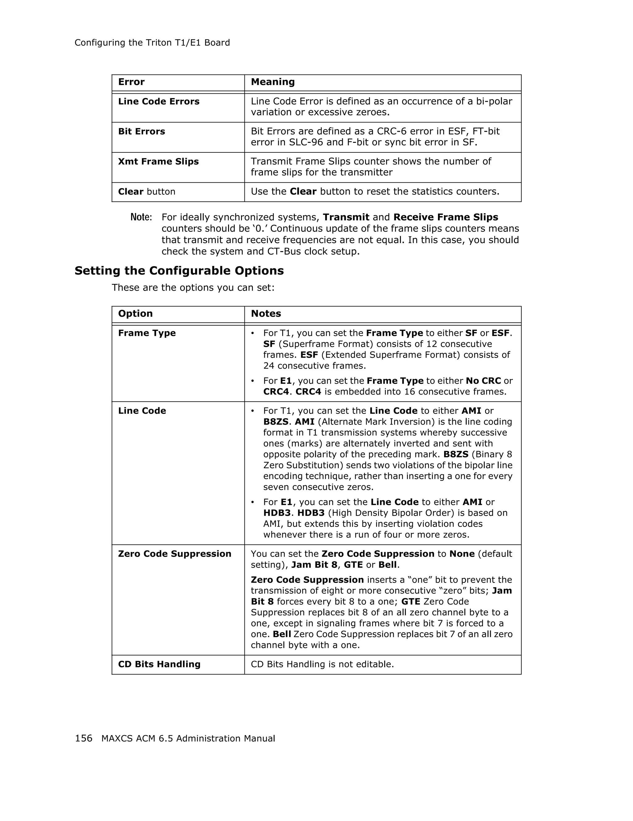
Reading the Statistics
The Statistics panel displays the number of errors that have occurred since the last
system reboot or statistics clearing. There may be non-zero values when configuring the
T1 span for the first time. You can clear these fields with the Clear button.
Error Meaning
Frame Errors Number of framing bit errors. In T1 mode, a framing bit
error is defined as an incorrect FS-bit value. The counter is
suppressed when framer loses frame alignment
OOF Errors The Out Of Frame counter registers every time the T1 chip
is forced to re-frame when receiving a frame with severe
errors.
Rec Frame Slips The Receiver Frame Slips counter shows the number of
frame slips for the receiver.
MAXCS ACM 6.5 Administration Manual 155](https://image.slidesharecdn.com/maxcsacm6-5administrationmanual-100910152521-phpapp02/75/AltiGen-M-A-X-C-S-A-C-M-6-169-2048.jpg)
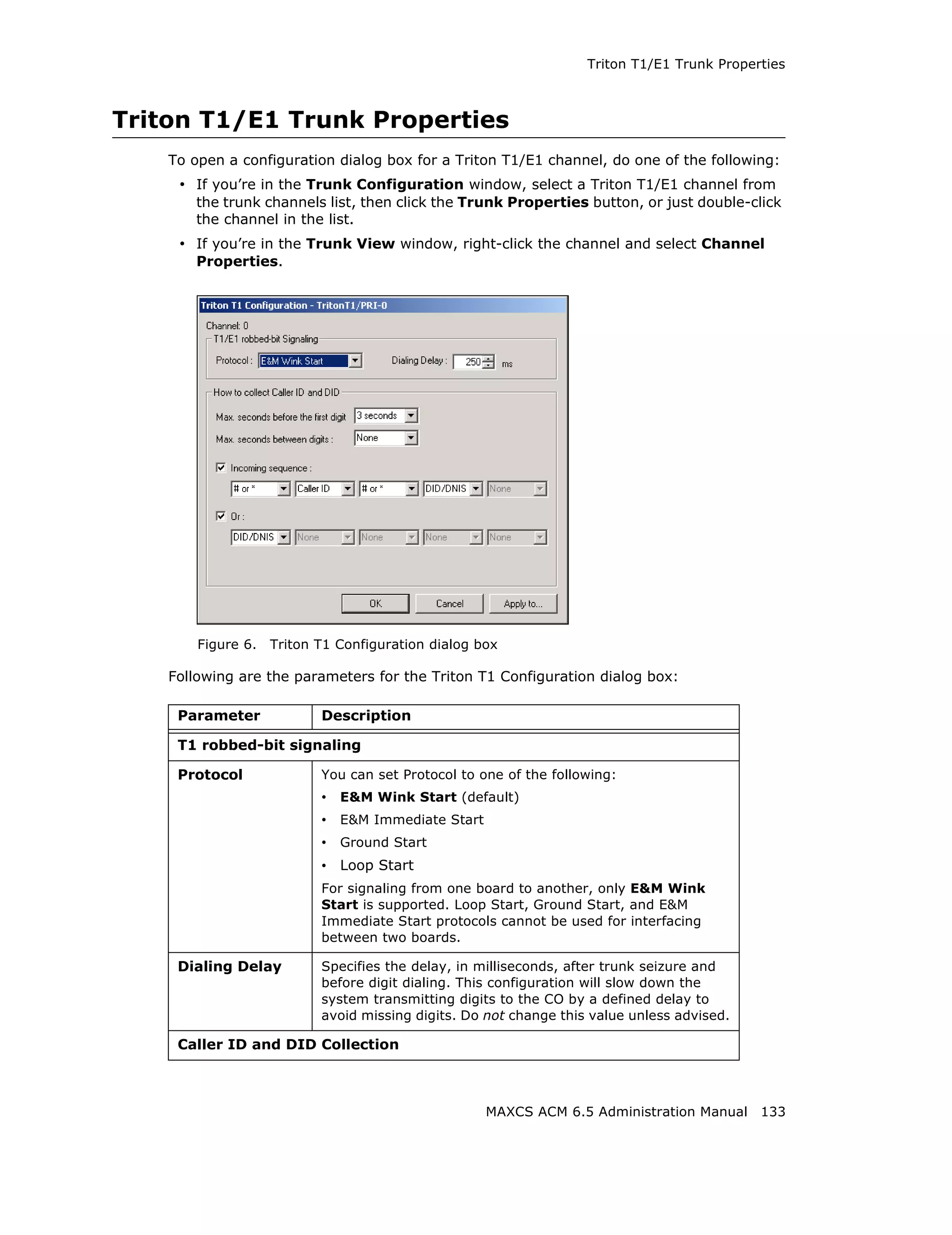
![Configuring the MAX1000/2000 Board
Configuring the MAX1000/2000 Board
The MAX1000/2000 Server is a telecom appliance that consists of an embedded DSP
board and two access board slots. MAXCS treats the entire MAX system as one board
with two access board options. The Boards window displays the name of the MAX board,
followed by [xxyy(-T1),xxyy]:
Figure 19. Boards View showing MAX board
xx refers to the number of analog trunks, and yy refers to the number of analog
extensions. If an access board has a T1/E1 port, -T1 is added to the end.
In the Boards window, double-click the MAX 1000/2000 board to open the main Board
Configuration window:
Figure 20. Board Configuration window
The Channel Group Info panel shows the channel groups (groups of channels that
belong to the same type). For example, if one 4x4xT1 access board and one 4x8 access
board are installed in the MAX 1000/2000 main board, there will be three channel groups
for the 4x4xT1 card, and two channel groups for the 4x8. When one of the channel
groups is selected, the Channel Mapping List reflects the selection.
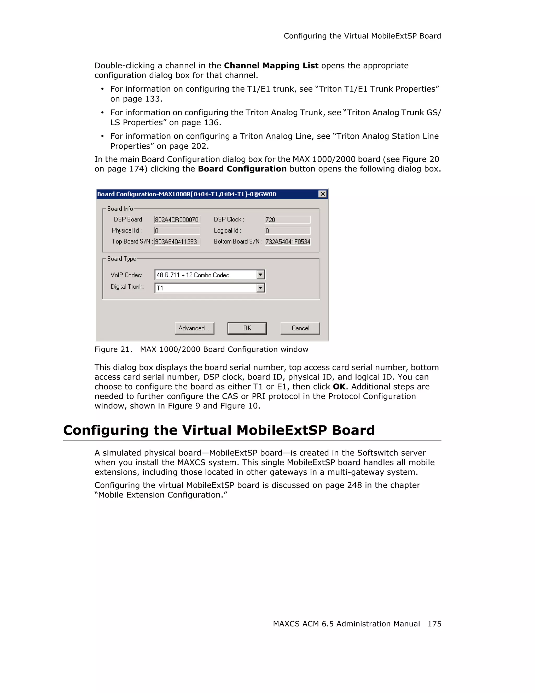
• Double-clicking a T1/E1 channel group opens the channel group configuration dialog
box. For information on configuring in this dialog box, see “T1 and E1 Configuration”
on page 153. This is available on T1 or E1 channel groups only.
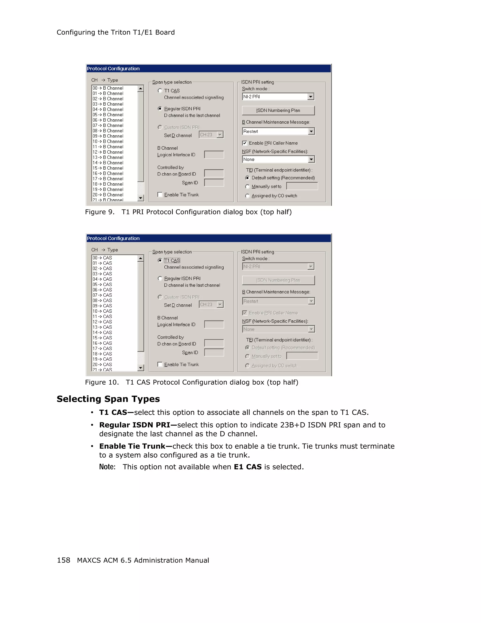
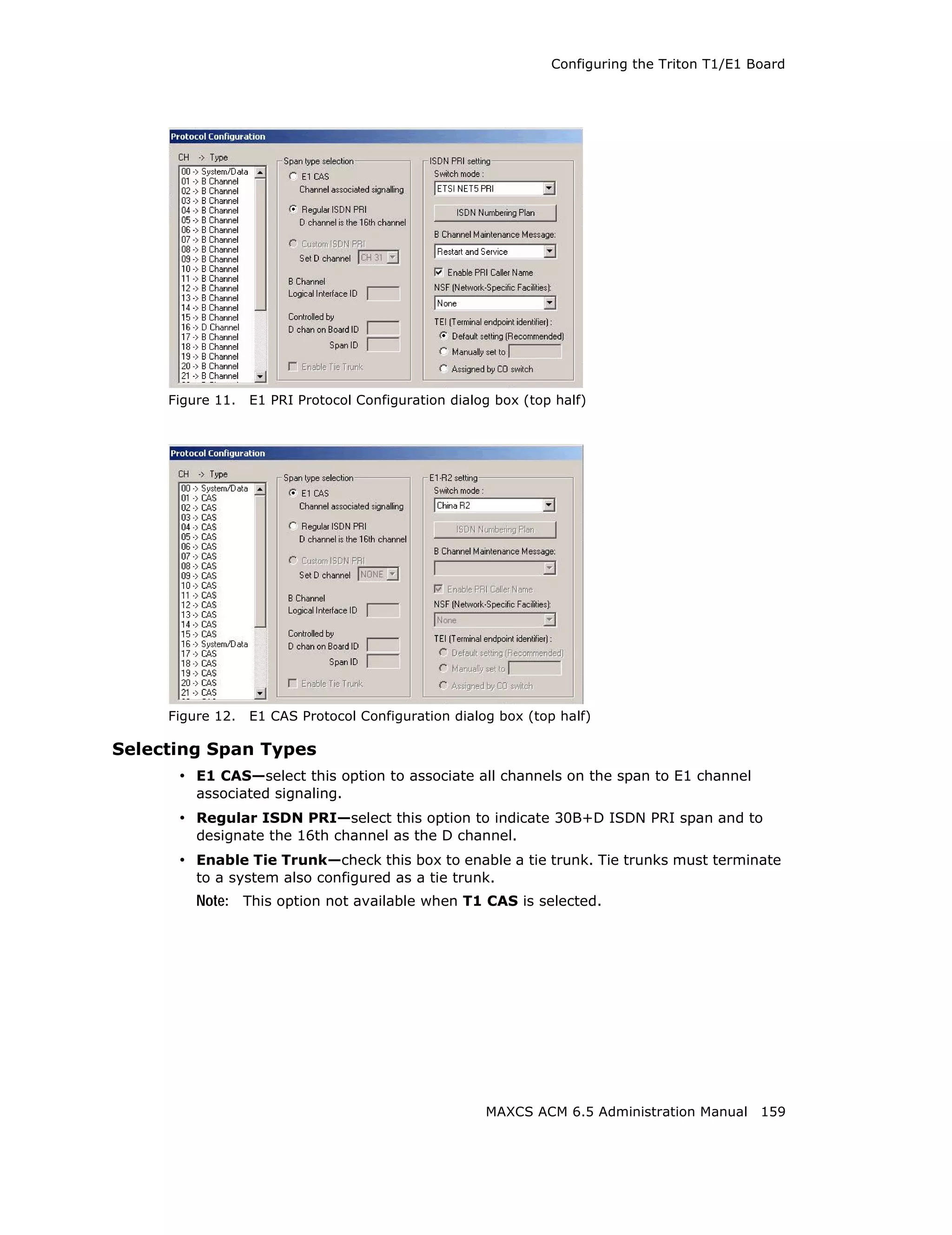
• In the channel group configuration dialog box, click the Protocol button to open the
Protocol Configuration dialog box. For information on configuring protocol, see
“Setting up Channels on the Triton T1/E1 Board” on page 157.
174 MAXCS ACM 6.5 Administration Manual](https://image.slidesharecdn.com/maxcsacm6-5administrationmanual-100910152521-phpapp02/75/AltiGen-M-A-X-C-S-A-C-M-6-188-2048.jpg)


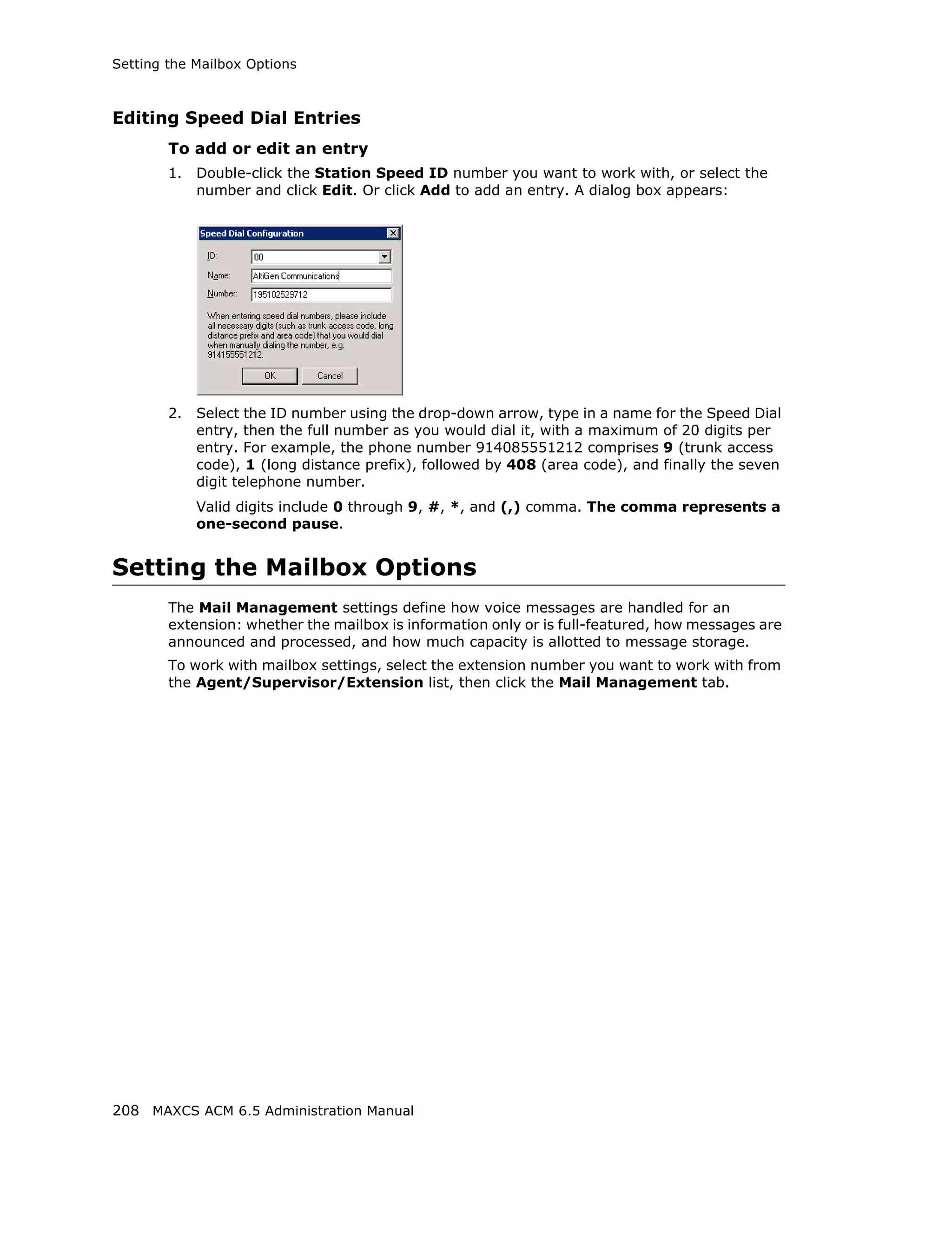
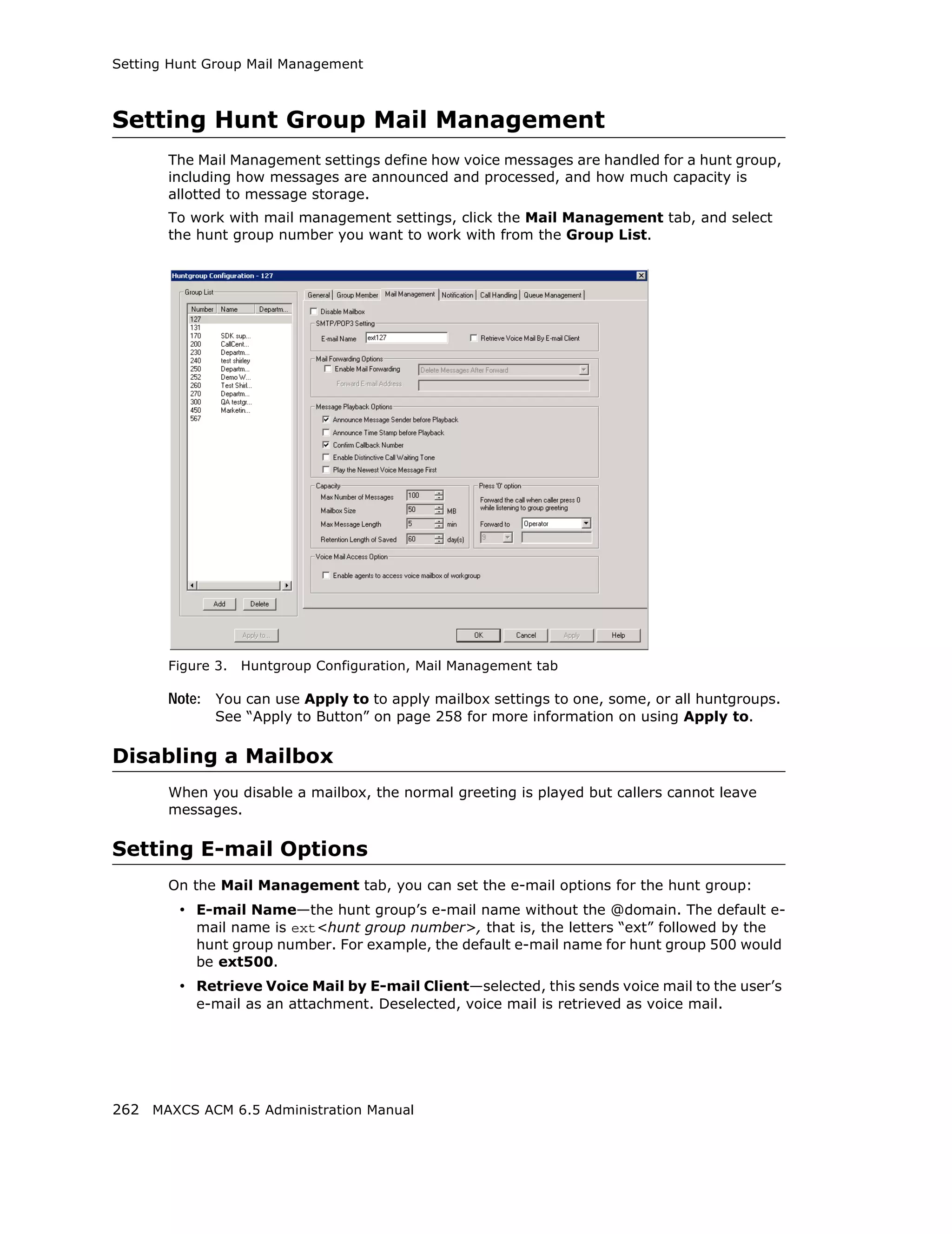
![Setting the Mailbox Options
SMTP/POP3 Setting
• Email Name—the user’s e-mail name without the @domain. The default e-mail
name is ext[extension number], that is, the letters “ext” followed by the extension
number. For example, the default e-mail name for extension 2497 would be
ext2497.
• Retrieve Voice Mail by Email Client—selected, this sends voice mail to the user’s
e-mail as an attachment.
Mail Forwarding Options
• Enable Mail Forwarding—selected, the user’s e-mail will be forwarded to the e-
mail address you specify in the Forward Email Address box. The address should
be a full address, including the domain (for example, jsmith@thecompany.com).
If you enable mail forwarding, you also specify what you want done with the original
messages after they have been forwarded. In the drop down list you can choose to:
– Delete Messages after Forward
– Keep the Messages as New
– Keep Messages as Saved
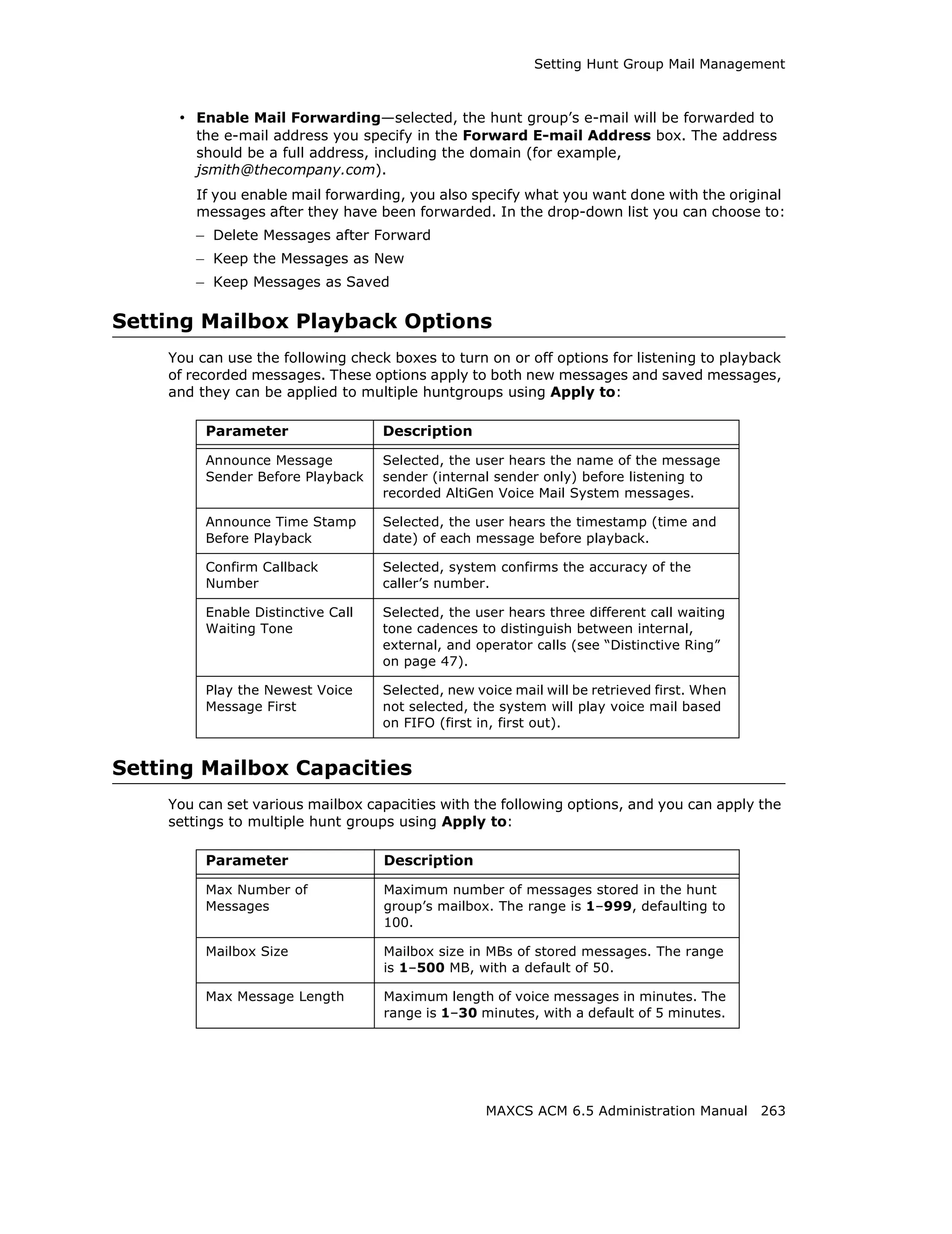
Setting Message Playback Options
You can use the following check boxes to turn on or off options for listening to playback
of recorded messages. These options apply to both new messages and saved messages,
and they can be applied to multiple extensions using Apply to.
Parameter Description
Announce Selected, the user hears the type of the message sender
Message Sender (internal or outside) before listening to recorded messages.
Before Playback
Announce Time Selected, the user hears the timestamp (time and date) of
Stamp Before each message before playback.
Playback
Confirm Callback Selected, the system reads back the caller’s number and asks
Number the caller to confirm.
Enable Distinctive Selected, the extension user will hear a "beep" tone when
Call Waiting Tone there is a call waiting in the extension's queue.
Play the Newest Selected, new voicemail will be retrieved first. When not
Voice Message selected, the system will play voicemail based on first-in-first-
First out (FIFO).
Press Zero Option
This option allows a caller to press “0” while listening to this extension’s greeting. Use
the drop-down list to select one of the following forwarding destinations for the call:
Voice Mail, AA, Extension, Group, Operator (default), Outside Number,
Application Extension, or Line Park. When the caller presses “0”, the call will forward
to the specified destination.
210 MAXCS ACM 6.5 Administration Manual](https://image.slidesharecdn.com/maxcsacm6-5administrationmanual-100910152521-phpapp02/75/AltiGen-M-A-X-C-S-A-C-M-6-224-2048.jpg)
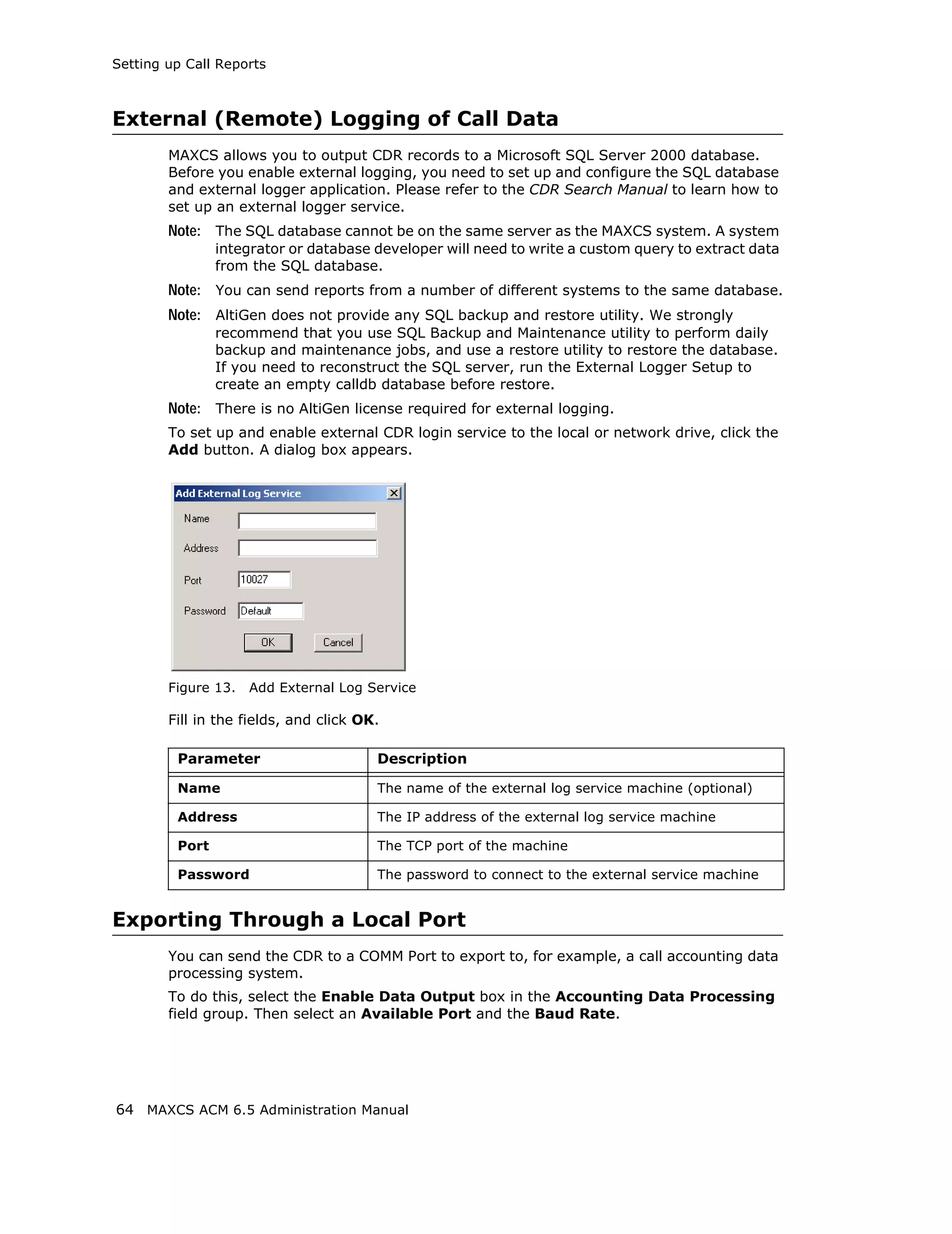
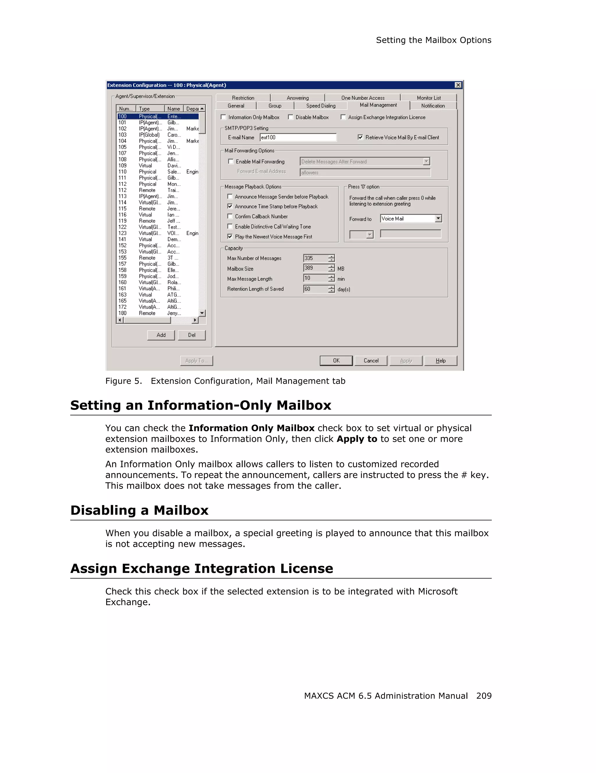
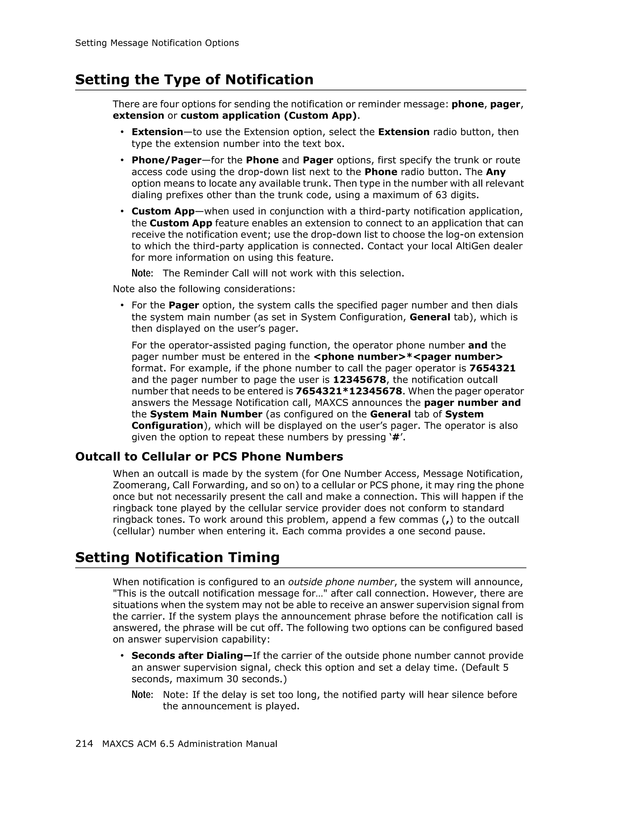
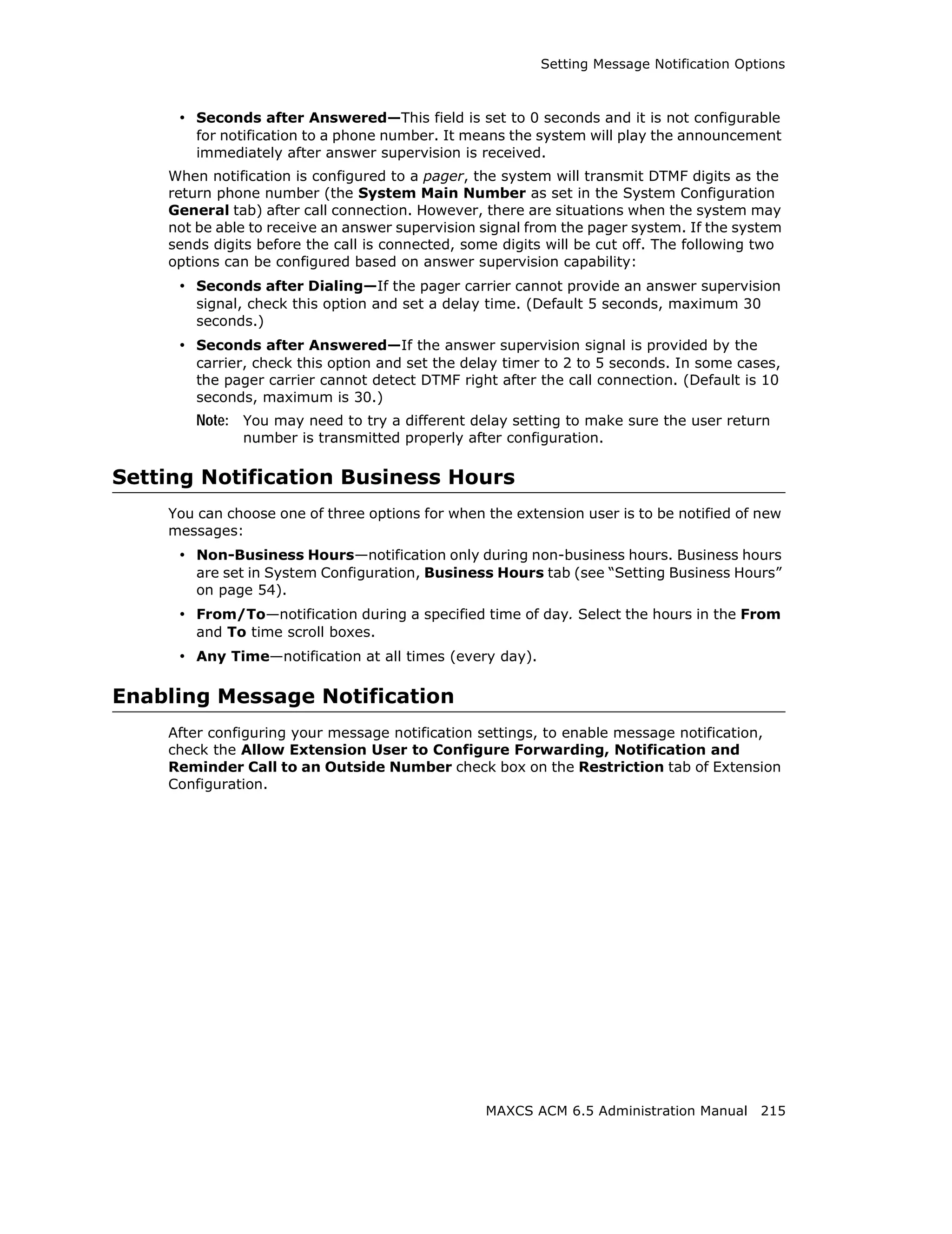
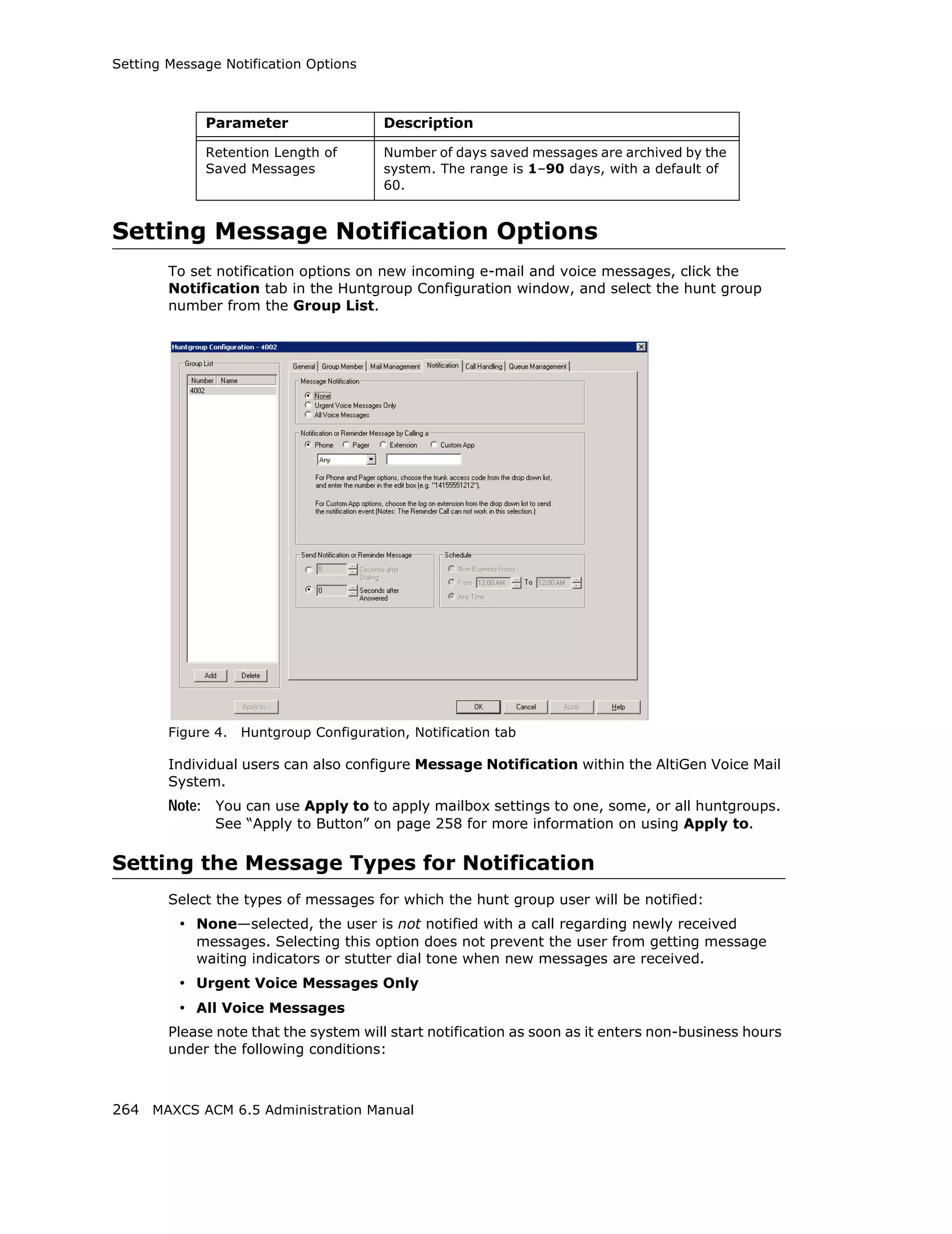
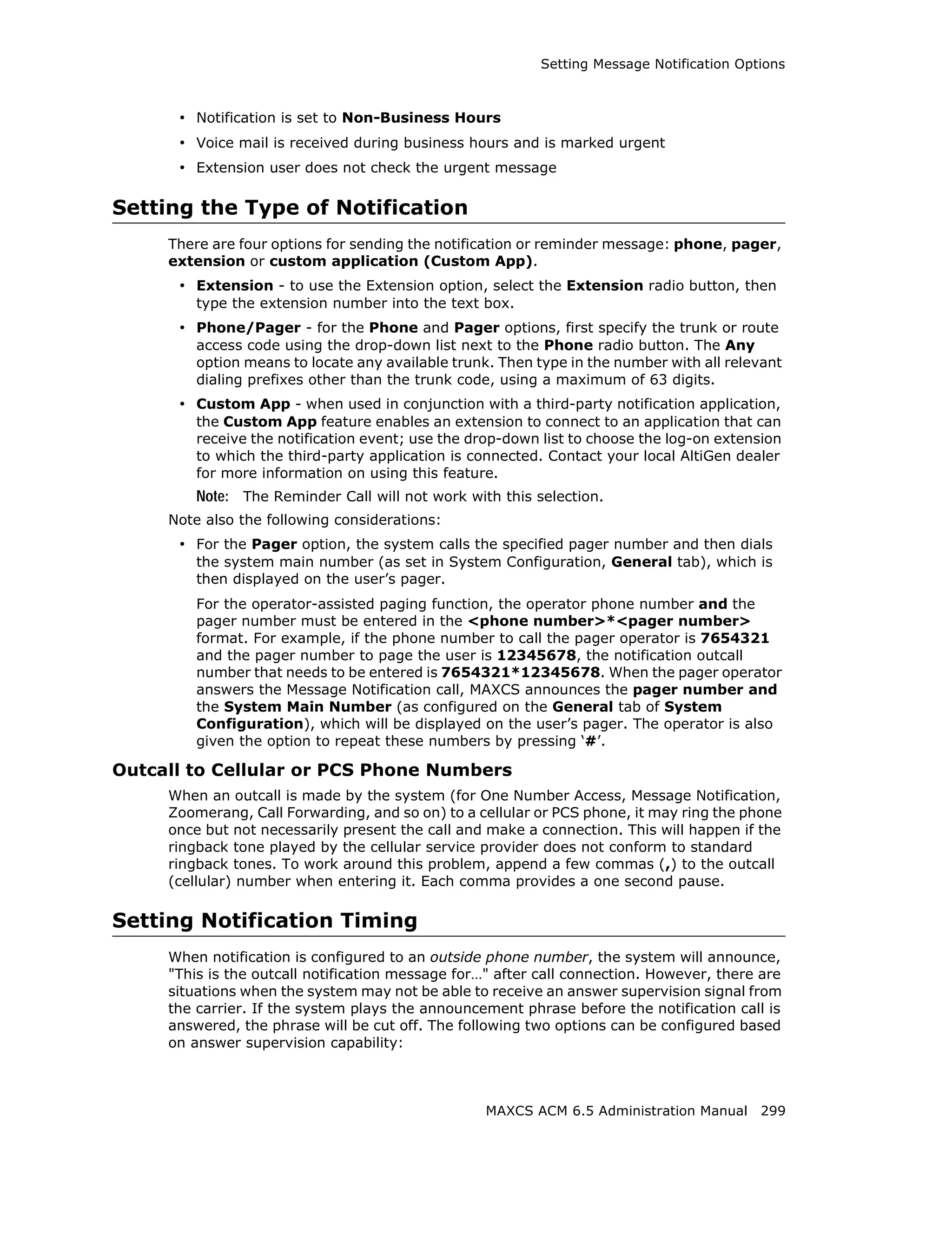
![Setting Message Notification Options
When the designated extension is notified, the system will play "Unusual call activity has
been detected from Extension xxx. More than yy calls have been made from the
extension's voice mail. Please verify with the extension user." Or "Unusual call activity
has been detected from Extension xxx. The extension made more than a yyy-minute call
from the extension's voice mail. Please verify with the extension user." The security
notification will be made only once within a call.
Setting Parameters for Unusual VM Activity
To change the parameters for the number of calls or length of a call, you must add the
following strings and values to the Windows registry:
• SecurityConnectionDuration (value range is from 1-1440 minutes [24 hours]). When
the setting is out of range, the default of 120 minutes will be used.
• SecurityNumberOfCalls (value range is from 1-100 calls). When the setting is out of
range, the default of 20 calls will be used.
Adding security values to the registry
To add one or both of the above security values to the Windows registry:
1. Choose Run from the Windows Start menu, type regedit, and click OK.
2. Go to HKEY_LOCAL_MACHINESOFTWAREAltiGen Communications,
Inc.AltiWareInitInfo.
3. On the right side of the Registry window, right-click and choose New > DWORD
Value.
4. Type one of the security strings listed above, then double-click the entry.
5. Choose Decimal as the Base option.
6. Type the value you want (see the allowed range listed above) in the Value data text
box, and click OK.
7. The value you enter appears in parentheses in the Data column.
8. For the values you entered in the registry to take effect, from the MaxAdmin menu,
choose Diagnostic > Trace. The Trace Filter dialog box opens. Click the Minute
Task button in the dialog box. Alternatively, you could restart the system for the
values to take effect.
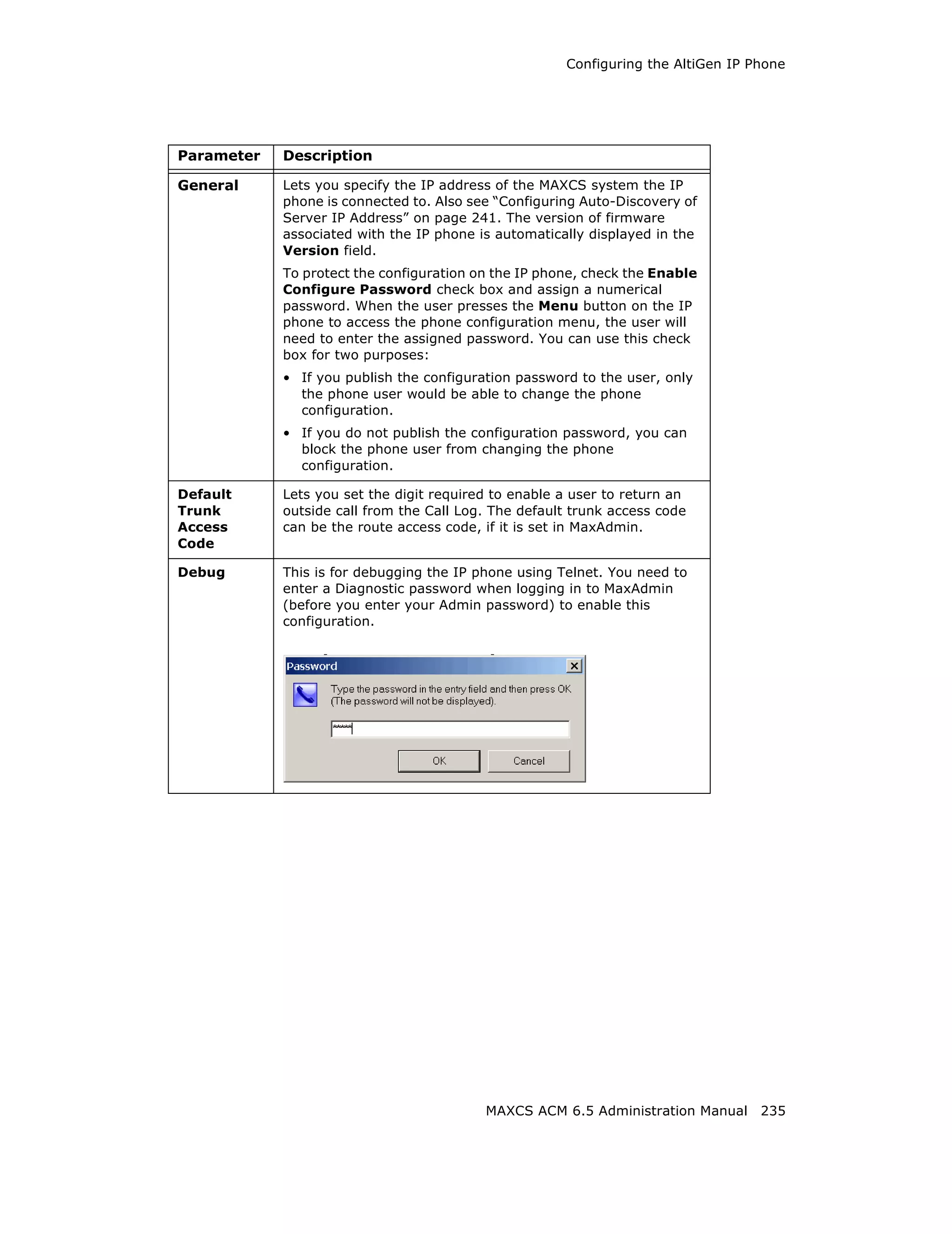
Note: To have access to the commands on the Diagnostic menu, you must first log
into MaxAdmin with the password jazzy and then again with the administrator
password.
Where Security Alerts Are Logged
Security alerts are logged to ...AltiServLogSecurityAlert.txt. The log includes
date, time, extension number, pad number, and the alert reason. Emergency calls are
also logged to this file. Following are some examples:
2007-02-04 08:30:25 Extension 212 made more than 20 calls from voicemail(1:2)
2007-02-04 16:00:50 Extension 395 made more than a 120-minute call from
voicemail(0:6).
2007-02-18 09:05:32 Extension 395(2:3) made an emergency call-###.
Note: A SecurityAlert.txt file does not appear in the ...AltiServLog folder until a
security alert event has created it.
MAXCS ACM 6.5 Administration Manual 213](https://image.slidesharecdn.com/maxcsacm6-5administrationmanual-100910152521-phpapp02/75/AltiGen-M-A-X-C-S-A-C-M-6-227-2048.jpg)

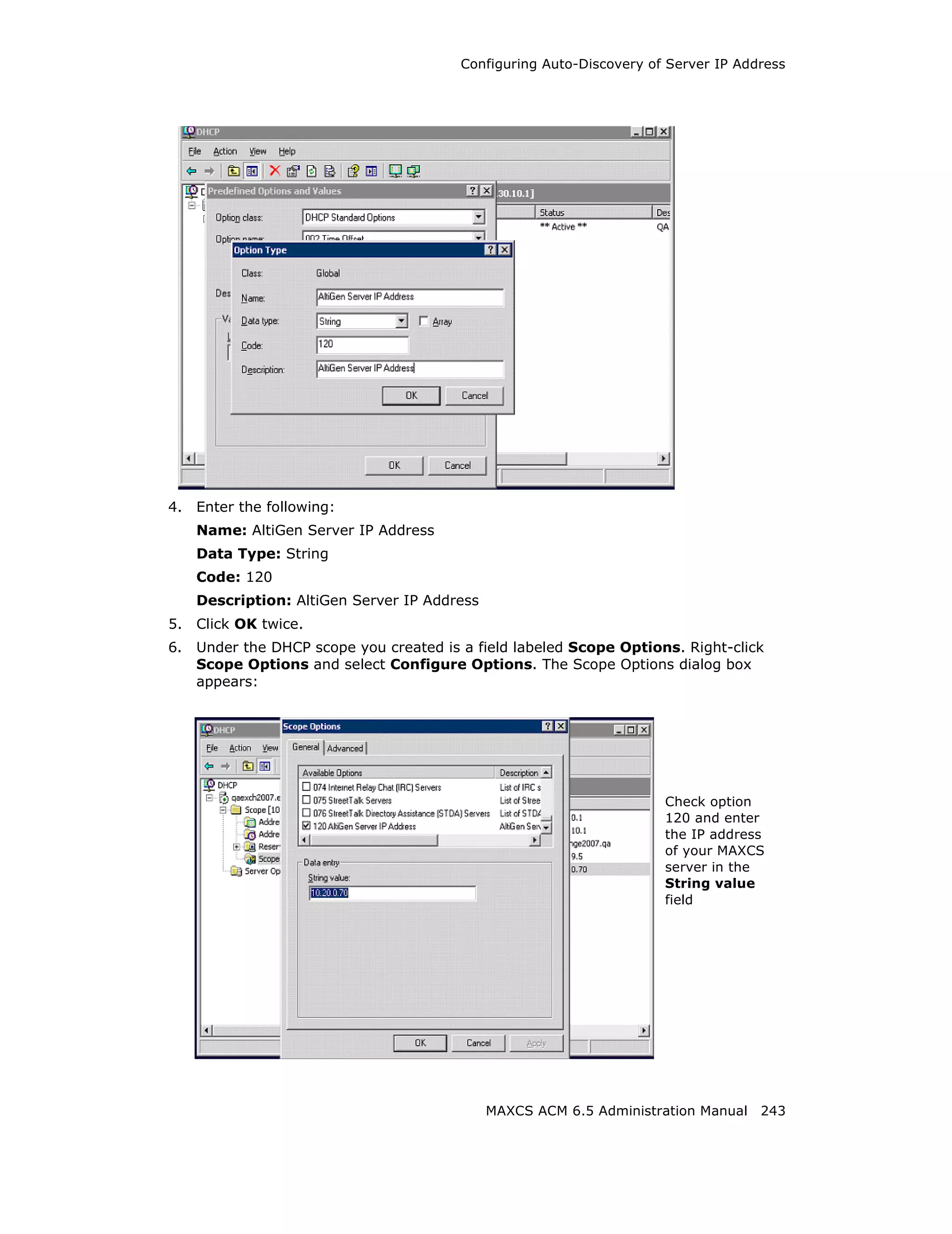
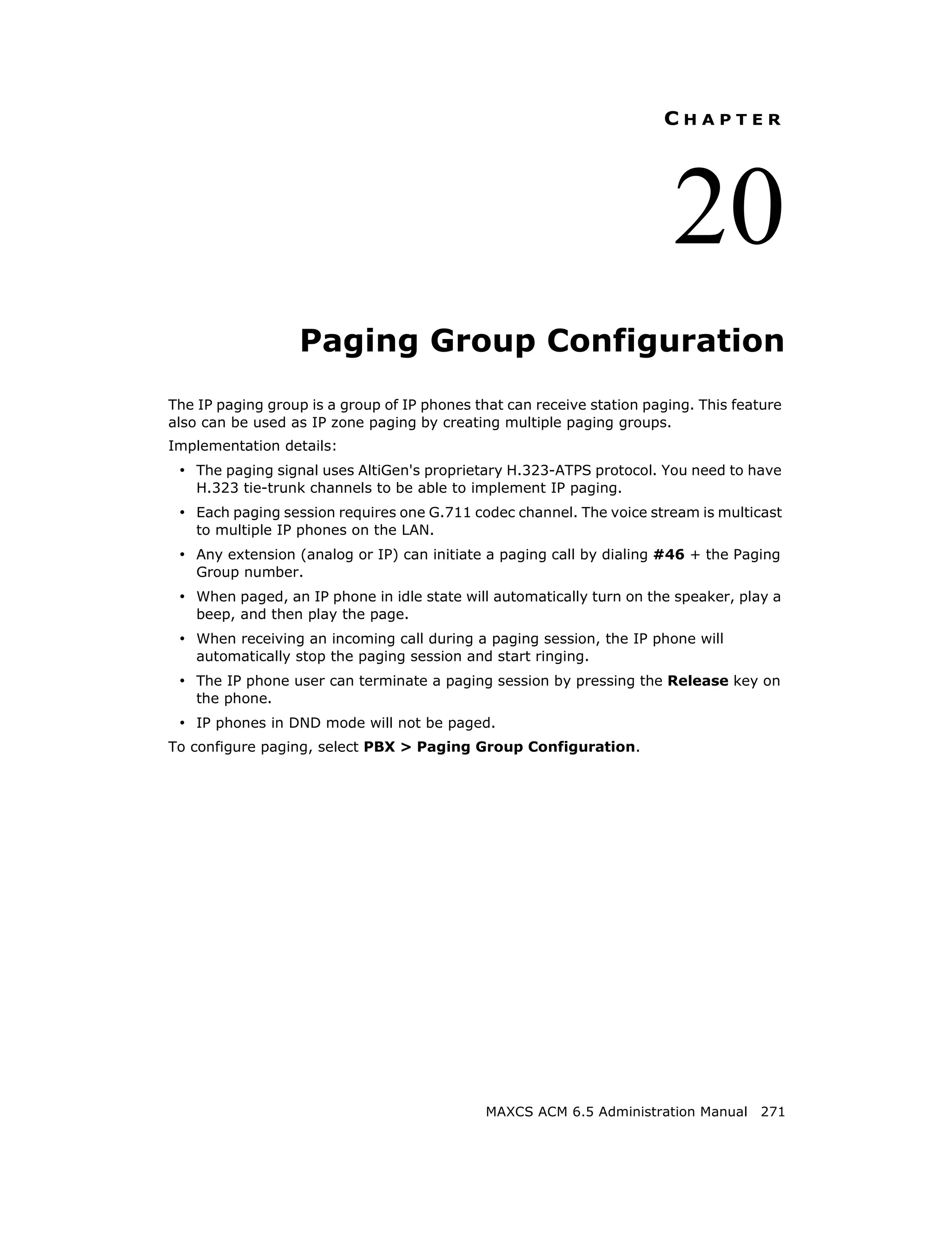
![Configuring Auto-Discovery of Server IP Address
7. Check option 120.
8. Enter the IP address of your MAXCS server in the String value field.
9. Click Apply and OK. You’ll see that the scope now shows option 120.
10. Right-click the scope option 120 and select Activate to activate the scope.
On the AltiGen IP Phone
The IP phone's System menu includes an item called Auto Discovery. The user can
select YES or NO for this menu item. The factory default is YES.
When you Upgrade Firmware
• When you upgrade from firmware that does not support Auto Discovery, Auto
Discovery will be disabled by default.
• When you upgrade from firmware that does support Auto Discovery, the Auto
Discovery setting will carry over.
• When the user erases the IP phone configuration by using **2 [enter] in the IP
phone menu, Auto Discovery will be enabled by default.
Possible scenarios
• During the IP phone’s start-up stage, if Enable DHCP is ON and Auto Discovery is
set to YES, the IP phone configures its IP address from DHCP, and at the same time,
it gets the MAXCS SERVER address from DHCP option 120. The user is then
prompted to set his extension number and password.
• If Enable DHCP is OFF, then the phone’s IP address and the MAXCS SERVER
address must be set manually.
• If Enable DHCP is ON and Auto Discovery is NO, the DHCP option 120 value is
not sent to the IP phone. The MAXCS SERVER address must be set manually.
• If Enable DHCP is ON and Auto Discovery is YES and DHCP option 120 is set, the
IP phone always gets a new IP address, and DHCP option 120 refreshes the value of
MAXCS SERVER, even if MAXCS SERVER already has a value. The screen pauses for
2 seconds while the IP phone gets the MAXCS IP address from DHCP 120.
244 MAXCS ACM 6.5 Administration Manual](https://image.slidesharecdn.com/maxcsacm6-5administrationmanual-100910152521-phpapp02/75/AltiGen-M-A-X-C-S-A-C-M-6-258-2048.jpg)


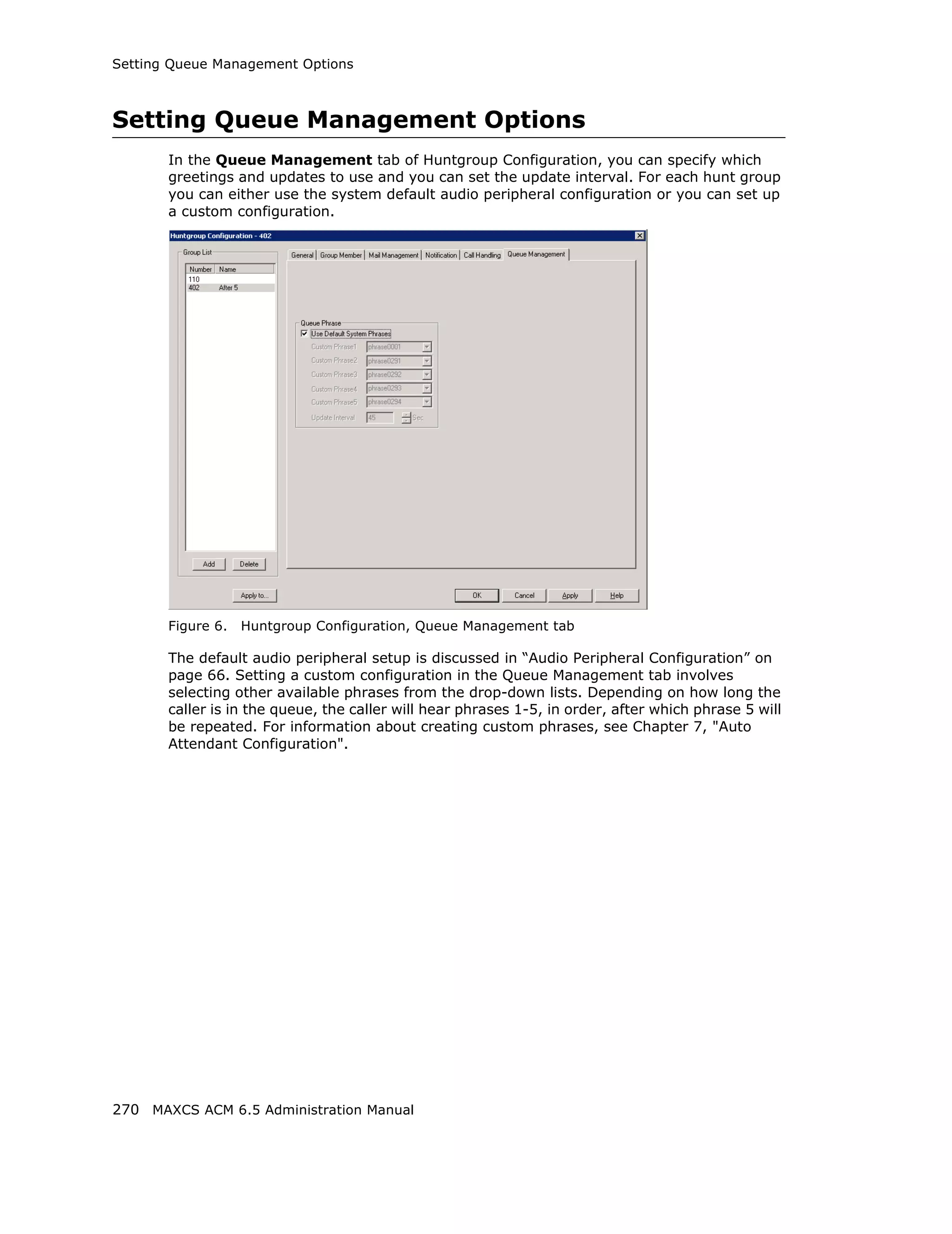

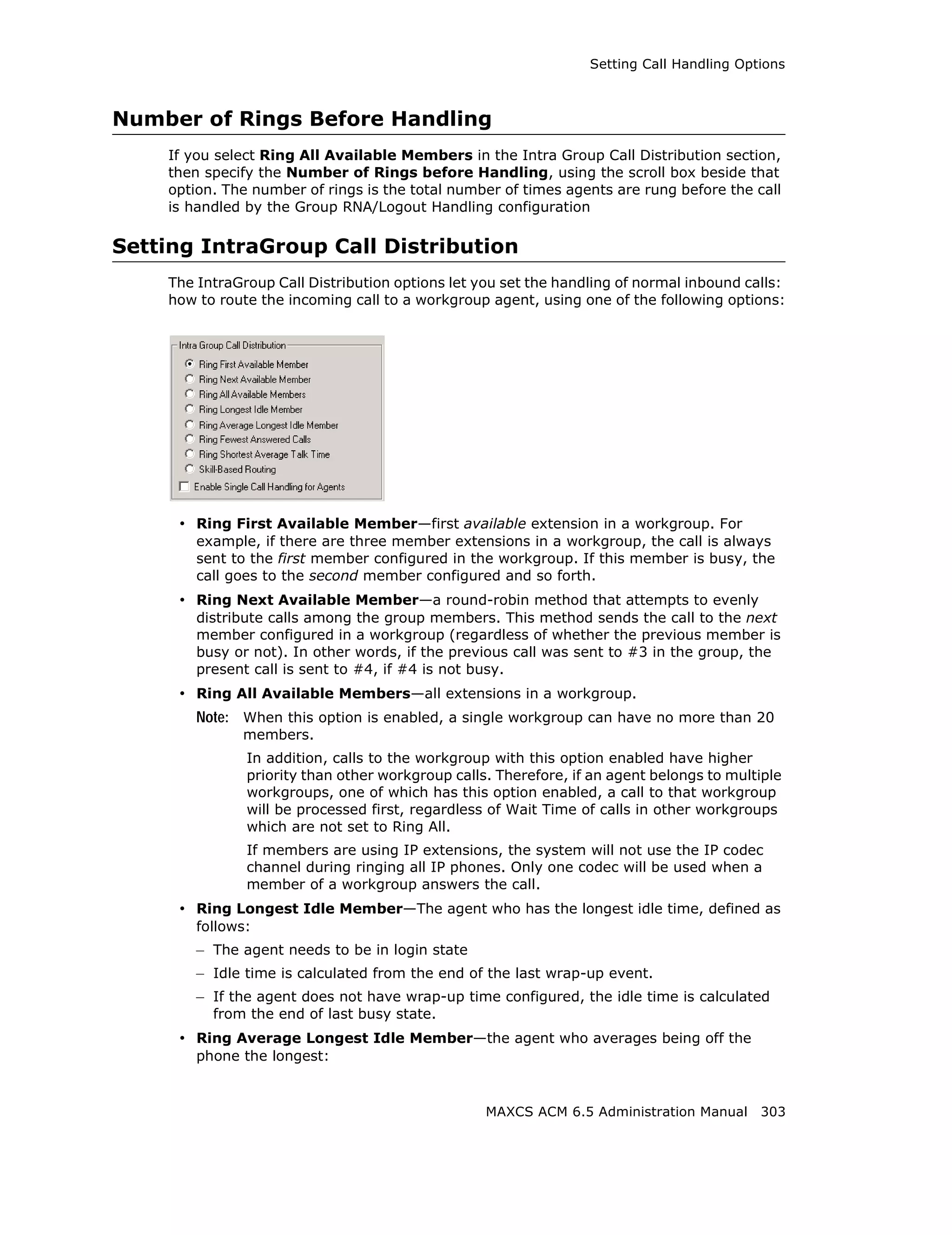
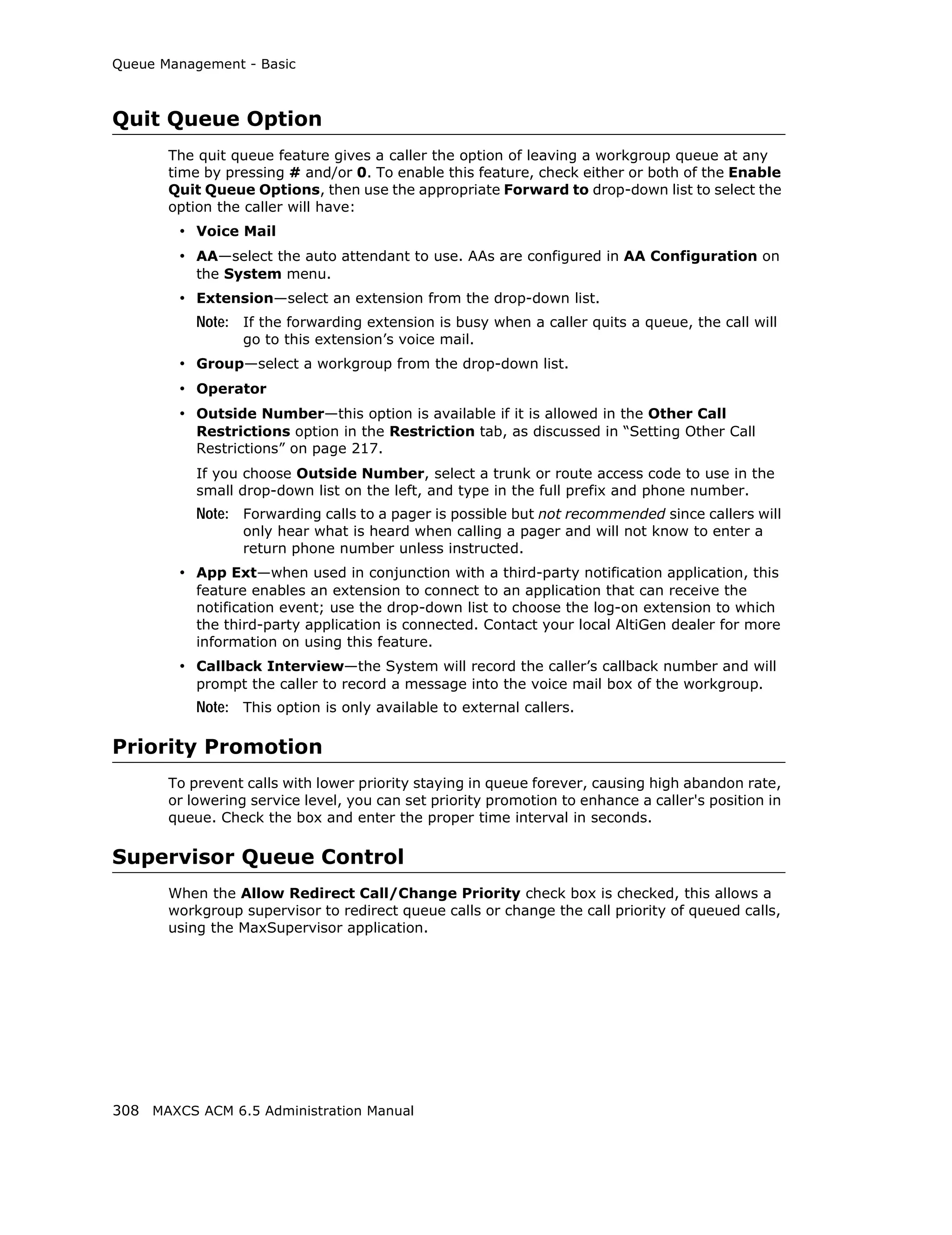
![Queue Management - Basic
Expected Queue Time - when checked, the system will tell the caller how long the wait
is expected to be. When calculating this number, the system will consider the average
agent call handling time and the position of the caller in queue. Because queue position
is a factor when calculating this number, do not check this option when call priority and
caller SKLR matching are configured. Please note that the Expected Queue Time is an
estimated number. Agents logging in or out of the workgroup during operation hours will
affect the actual handling time and cause deviation to the expected queue time.
Expected Queue Time (round up to minutes) = [(Average Call Handling Time
x Queue Position) + 59 sec] / 60 sec
Expected Wait Time Sampling
To calculate Expected Queue Time, the system needs to take samples when a workgroup
starts operation. You can set the following parameters to set a sampling period and a
fixed Expected Queue Time announcement during sampling period. The expected queue
time counter is reset for all workgroups daily at midnight.
• Initial Sample Call Count [1 to 100] - How many calls you would like to use as
initial samples.
• Initial Expected Wait (Queue) Time [1 to 10 minutes] - This field defines the
expected queue time to be announced during the sampling period.
Queue Overflow Forwarding
The Queue Overflow Forwarding options are for handling long queues or long wait times
for callers. When a queue exceeds a set number of calls, or callers are waiting beyond a
set length of time, calls can be automatically forwarded to a voicemail box, AA,
extension, group, operator, outside number, or application extension.
To set options for handling queue overflow:
1. In the Queue Overflow Forwarding section, set options for:
• Calls in queue exceed - when the number of calls in queue are greater than the
defined number, new incoming calls will be overflowed to the defined target.
• Expected queue time longer than - when the longest queue time is greater
than the specified number of minutes, new incoming calls will be overflowed to
the defined target.
• Service level lower than - this number is not a historical service level defined
in the workgroup threshold. This number is a real-time queue service level (RTSL)
calculated as follows:
RTSL% = 1 - (# of queued calls exceed SL threshold / Total calls
in queue)
2. Check the Enable Forward to check box and from the drop-down list, select the
forwarding destination list to use if the queue length, wait time or service level
settings are exceeded. If this option is not checked, calls will go to the workgroup’s
voicemail.
MAXCS ACM 6.5 Administration Manual 307](https://image.slidesharecdn.com/maxcsacm6-5administrationmanual-100910152521-phpapp02/75/AltiGen-M-A-X-C-S-A-C-M-6-321-2048.jpg)


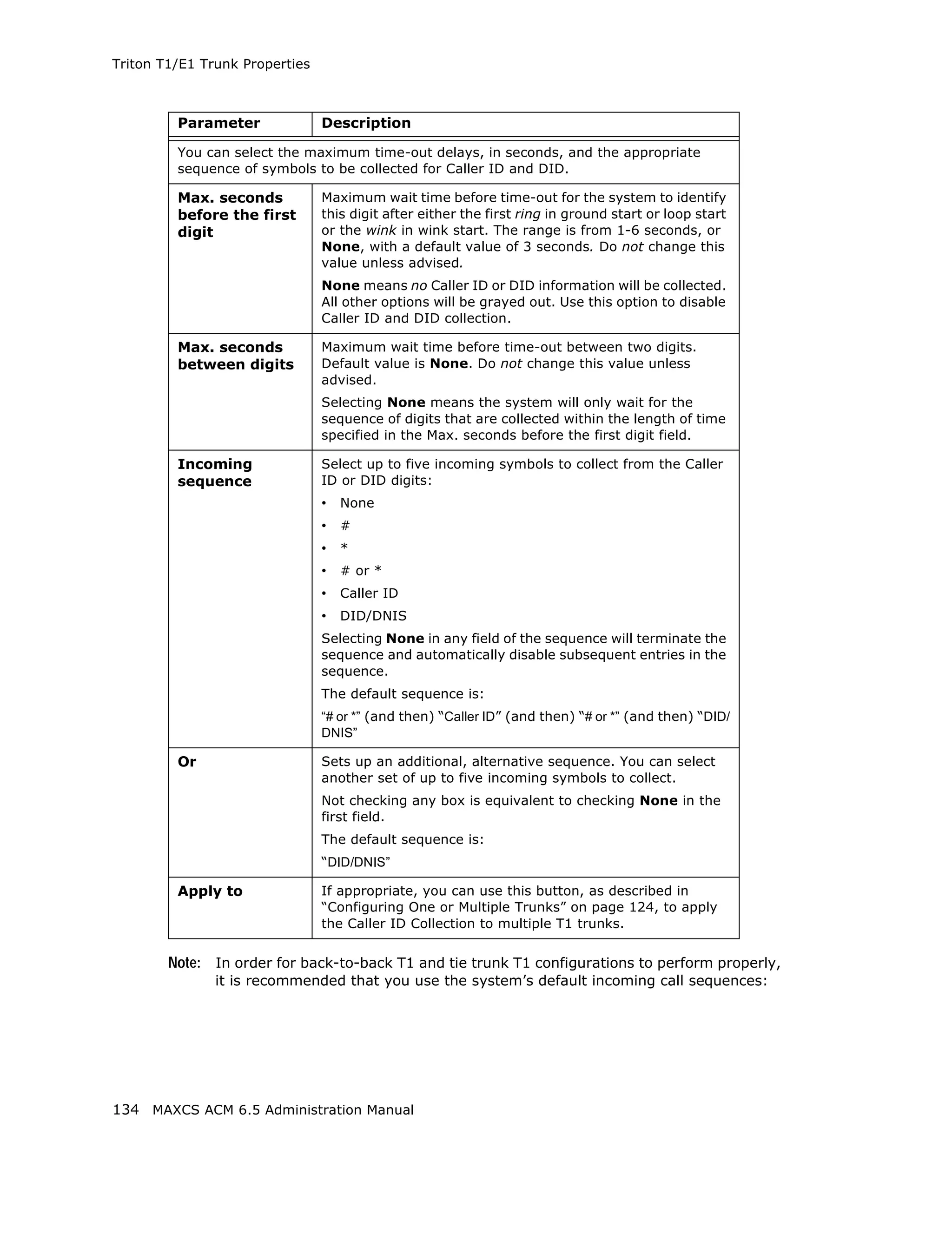
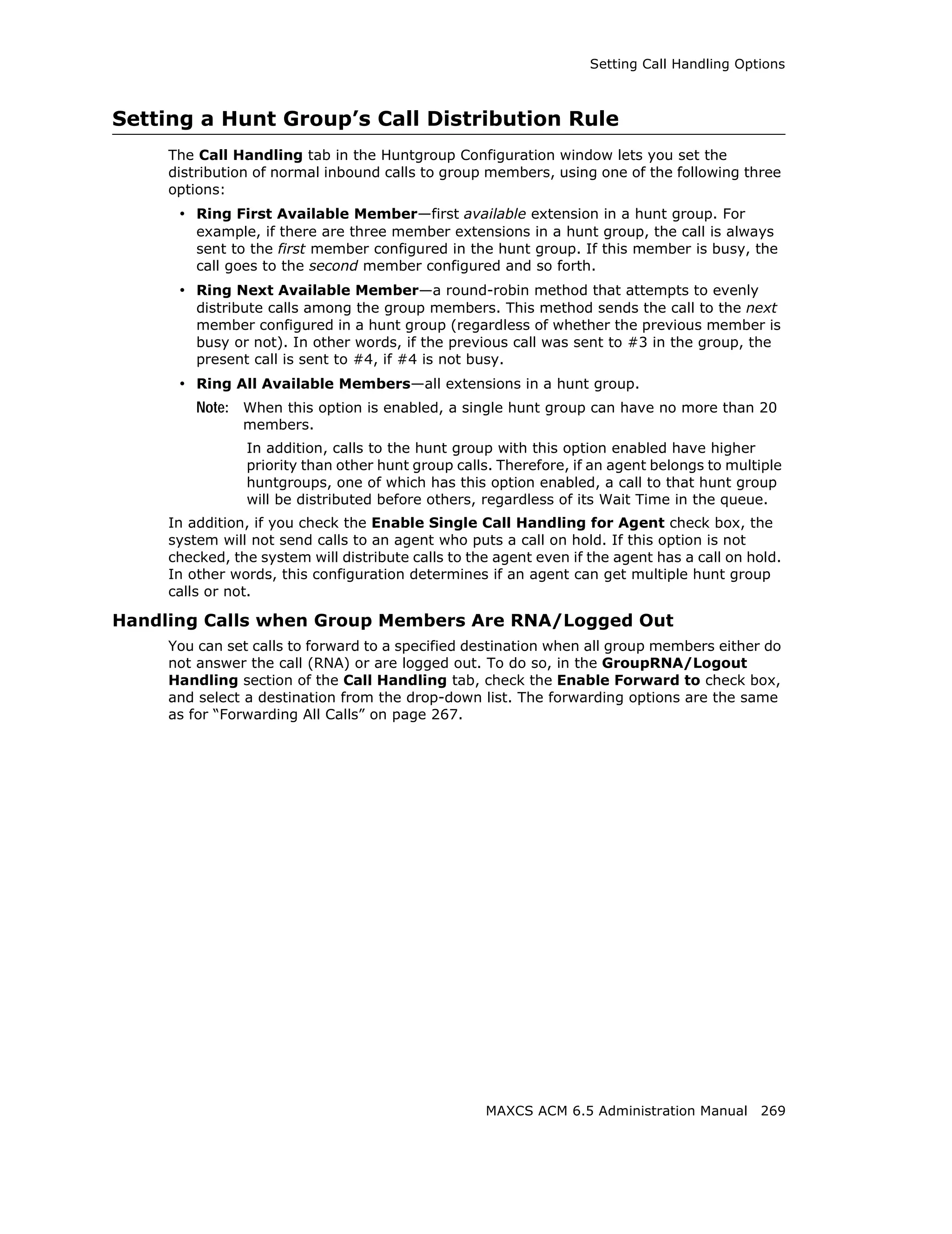
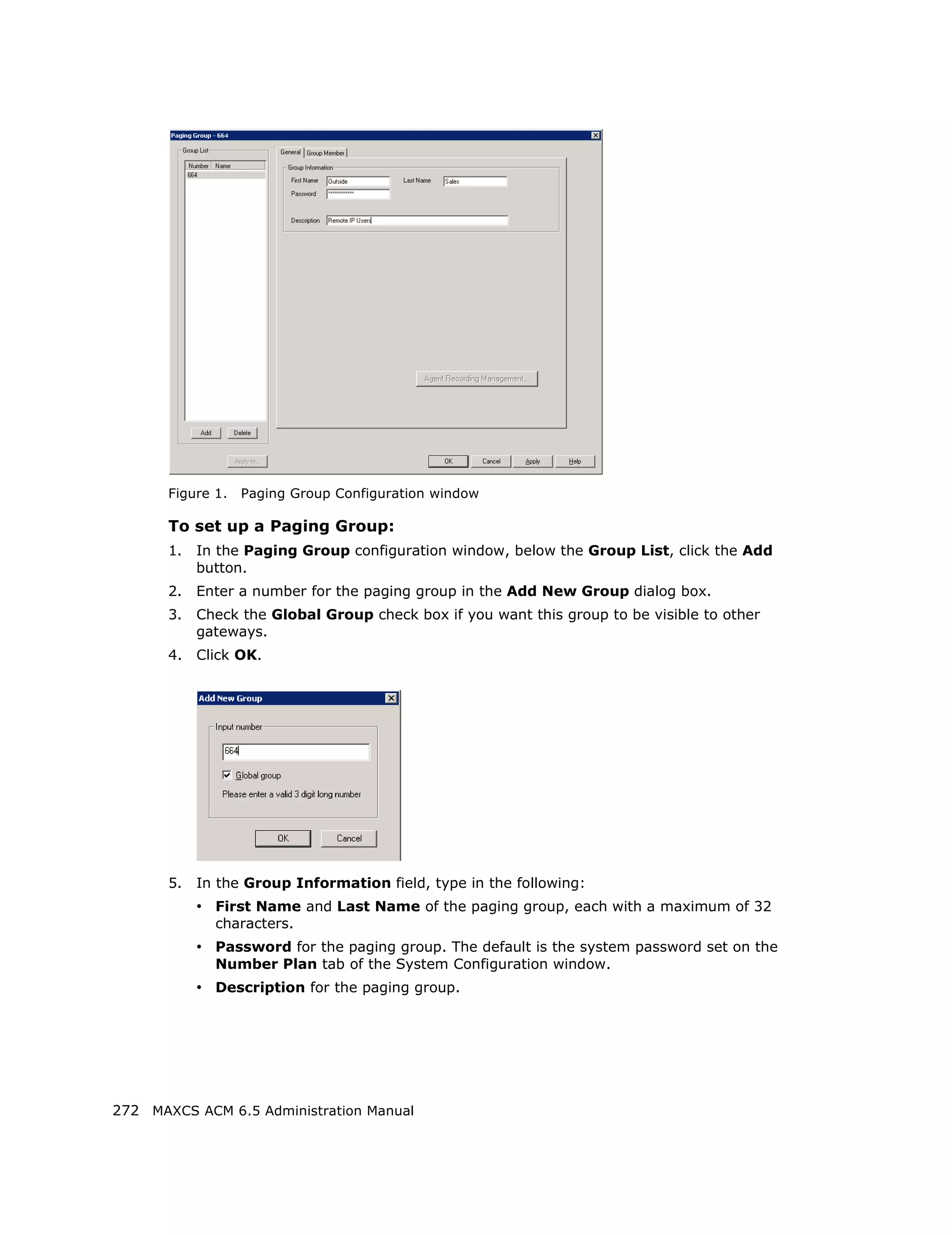
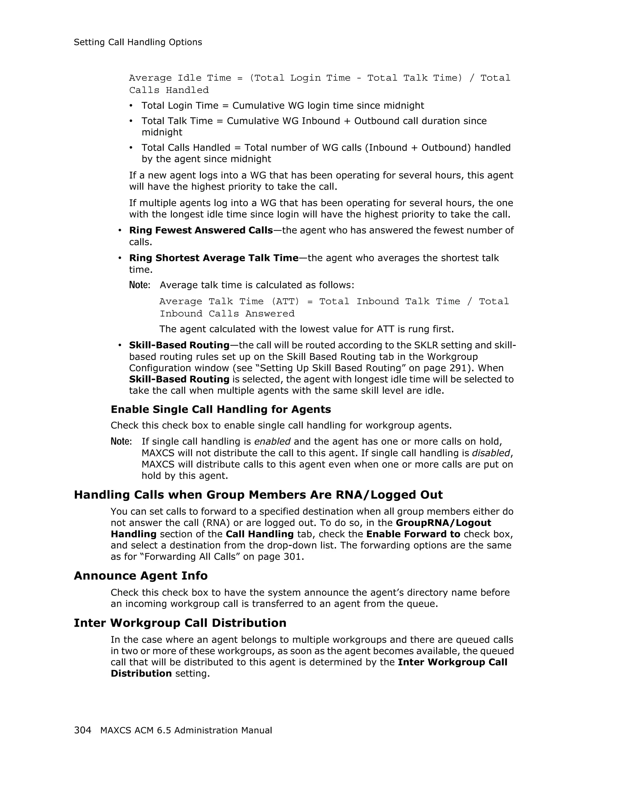
![Table 1. Signaling values, by country
Country Signaling Values
Chile/Nacional MFC- Set calling part category: 1
R2 [Assume no caller ID provided]:
Incoming sequence: DID/DNIS
In-call signaling (depend on how many DID digits):
For 3-digit DID, set to (113)6
For 4-digit DID, set to (1113)6
For 5-digit DID, set to (11113)6
For 6-digit DID, set to (111113)6
For 7-digit DID, set to (1111113)6
For 8-digit DID, set to (11111113)6
[Assume caller ID provided]:
Incoming sequence (same as above shown): DID/
DNIS * Caller ID
In-call signaling (depend on how many DID digits):
For 3-digit DID, set to (115)*(K)36
For 4-digit DID, set to (1115)*(K)36
For 5-digit DID, set to (11115)*(K)36
For 6-digit DID, set to (111115)*(K)36
For 7-digit DID, set to (1111115)*(K)36
For 8-digit DID, set to (11111115)*(K)36
454 MAXCS ACM 6.5 Administration Manual](https://image.slidesharecdn.com/maxcsacm6-5administrationmanual-100910152521-phpapp02/75/AltiGen-M-A-X-C-S-A-C-M-6-468-2048.jpg)
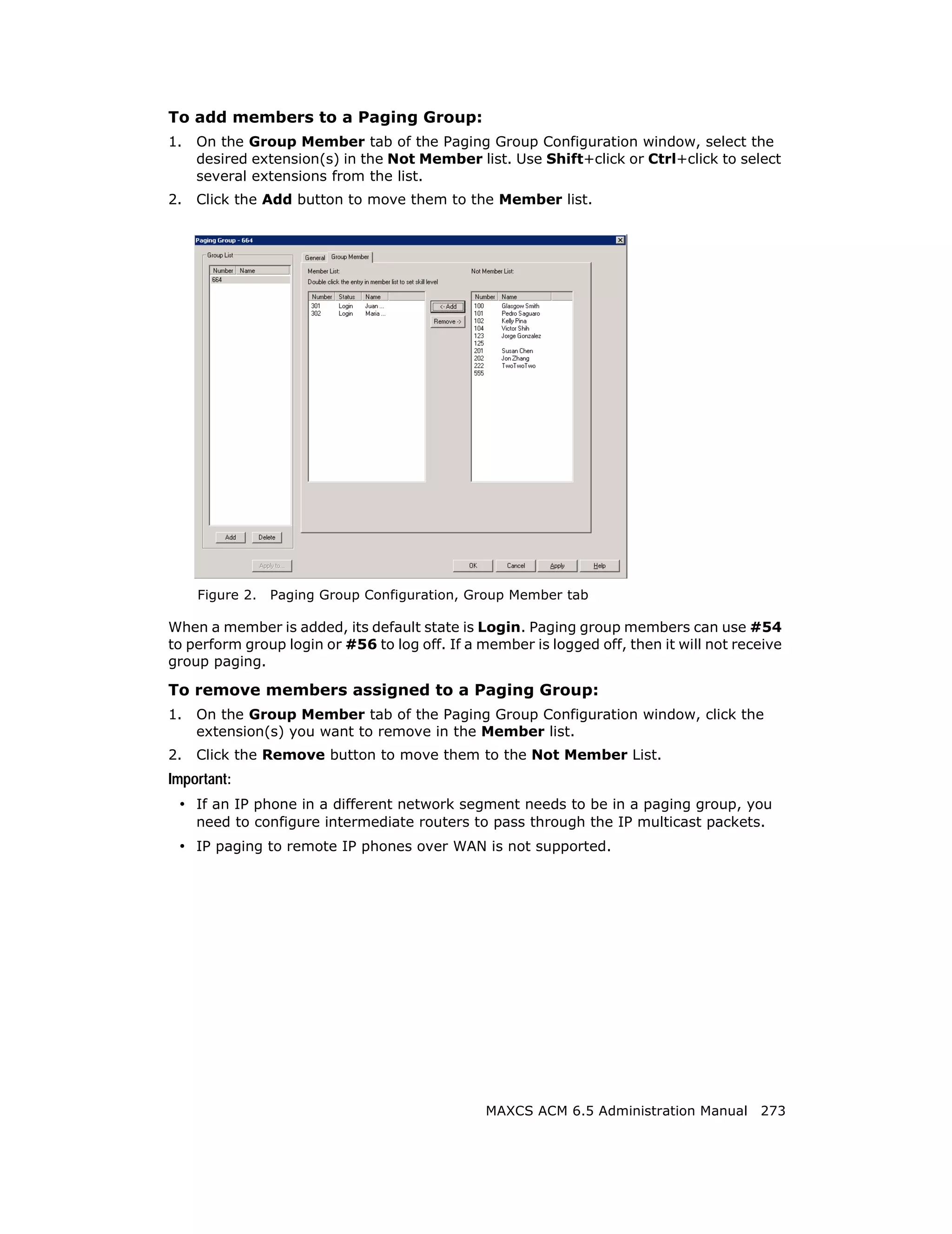
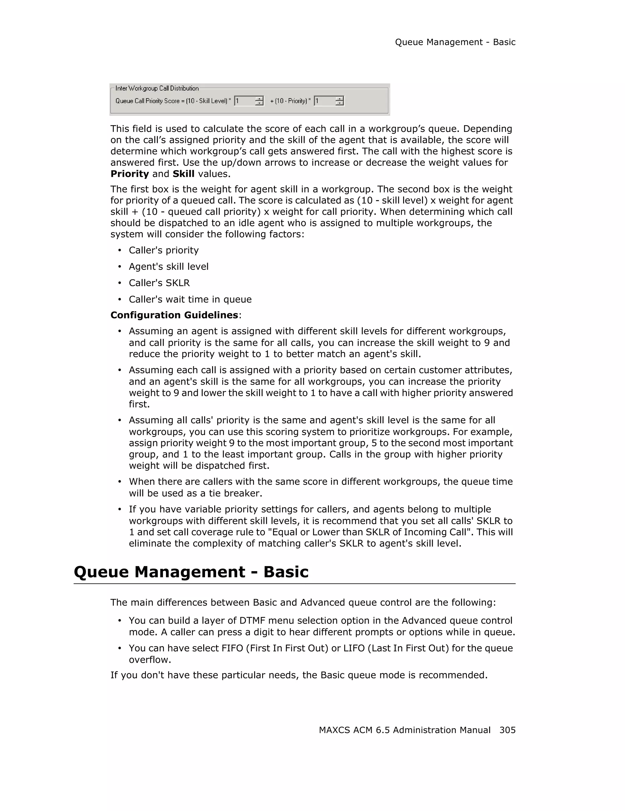
![Country Signaling Values
China MFC-R2 Set calling part category: 3
[Assume no caller ID provided]:
Incoming sequence: DID/DNIS
In-call signaling (depend on how many DID digits):
For 3-digit DID, set to (113)1
For 4-digit DID, set to (1113)1
For 5-digit DID, set to (11113)1
For 6-digit DID, set to (111113)1
For 7-digit DID, set to (1111113)1
For 8-digit DID, set to (11111113)1
[Assume caller ID provided]:
Incoming sequence (same as above shown):
DID/DNIS * Caller ID
In-call signaling (depend on how many DID digits):
For 3-digit DID, set to (116)*(K)31
For 4-digit DID, set to (1116)*(K)31
For 5-digit DID, set to (11116)*(K)31
For 6-digit DID, set to (111116)*(K)31
For 7-digit DID, set to (1111116)*(K)31
For 8-digit DID, set to (11111116)*(K)31
Colombia MFC-R2 Set calling part category: 2
[Assume no caller ID provided]:
Incoming sequence: DID/DNIS
In-call signaling (depend on how many DID digits):
For 3-digit DID, set to (113)6
For 4-digit DID, set to (1113)6
For 5-digit DID, set to (11113)6
For 6-digit DID, set to (111113)6
For 7-digit DID, set to (1111113)6
For 8-digit DID, set to (11111113)6
[Assume caller ID provided]:
Incoming sequence (same as above shown):
DID/DNIS * Caller ID
In-call signaling (depend on how many DID digits):
For 3-digit DID, set to (115)*(K)36
For 4-digit DID, set to (1115)*(K)36
For 5-digit DID, set to (11115)*(K)36
For 6-digit DID, set to (111115)*(K)36
For 7-digit DID, set to (1111115)*(K)36
For 8-digit DID, set to (11111115)*(K)36
MAXCS ACM 6.5 Administration Manual 455](https://image.slidesharecdn.com/maxcsacm6-5administrationmanual-100910152521-phpapp02/75/AltiGen-M-A-X-C-S-A-C-M-6-469-2048.jpg)
![Country Signaling Values
Ecuador MFC-R2 Set calling part category: 1
[Assume no caller ID provided]:
Incoming sequence: DID/DNIS
In-call signaling (depend on how many DID digits):
For 3-digit DID, set to (113)6
For 4-digit DID, set to (1113)6
For 5-digit DID, set to (11113)6
For 6-digit DID, set to (111113)6
For 7-digit DID, set to (1111113)6
For 8-digit DID, set to (11111113)6
[Assume caller ID provided]:
Incoming sequence (same as above shown):
DID/DNIS * Caller ID
In-call signaling (depend on how many DID digits):
For 3-digit DID, set to (115)*(K)36
For 4-digit DID, set to (1115)*(K)36
For 5-digit DID, set to (11115)*(K)36
For 6-digit DID, set to (111115)*(K)36
For 7-digit DID, set to (1111115)*(K)36
For 8-digit DID, set to (11111115)*(K)36
Ecuador MFC-LME Set calling part category: 2
[The switch doesn't support caller ID transmission]:
Incoming sequence: DID/DNIS
In-call signaling (depend on how many DID digits):
For 3-digit DID, set to (113)1
For 4-digit DID, set to (1113)1
For 5-digit DID, set to (11113)1
For 6-digit DID, set to (111113)1
For 7-digit DID, set to (1111113)1
For 8-digit DID, set to (11111113)1
Korea MFC-R2 Set calling part category: 1
[The switch doesn't support caller ID transmission]:
Incoming sequence: DID/DNIS
In-call signaling (depend on how many DID digits):
For 3-digit DID, set to (113)6
For 4-digit DID, set to (1113)6
For 5-digit DID, set to (11113)6
For 6-digit DID, set to (111113)6
For 7-digit DID, set to (1111113)6
For 8-digit DID, set to (11111113)6
456 MAXCS ACM 6.5 Administration Manual](https://image.slidesharecdn.com/maxcsacm6-5administrationmanual-100910152521-phpapp02/75/AltiGen-M-A-X-C-S-A-C-M-6-470-2048.jpg)
![Country Signaling Values
Mexico / Teléfonos de Set calling part category: 2
Mexico [Assume no caller ID provided]:
Incoming sequence: DID/DNIS
In-call signaling (depend on how many DID digits):
For 3-digit DID, set to (113)1
For 4-digit DID, set to (1113)1
For 5-digit DID, set to (11113)1
For 6-digit DID, set to (111113)1
For 7-digit DID, set to (1111113)1
For 8-digit DID, set to (11111113)1
[Assume caller ID provided]:
Incoming sequence (same as above shown):
DID/DNIS * Caller ID
In-call signaling (depend on how many DID digits):
For 3-digit DID, set to (116)*(K)31
For 4-digit DID, set to (1116)*(K)31
For 5-digit DID, set to (11116)*(K)31
For 6-digit DID, set to (111116)*(K)31
For 7-digit DID, set to (1111116)*(K)31
For 8-digit DID, set to (11111116)*(K)31
MAXCS ACM 6.5 Administration Manual 457](https://image.slidesharecdn.com/maxcsacm6-5administrationmanual-100910152521-phpapp02/75/AltiGen-M-A-X-C-S-A-C-M-6-471-2048.jpg)
![Country Signaling Values
Panamá / Nacional Set calling part category: 1
MFC-R2 [Assume no caller ID provided]:
Incoming sequence: DID/DNIS
In-call signaling (depend on how many DID digits):
For 3-digit DID, set to (113)6
For 4-digit DID, set to (1113)6
For 5-digit DID, set to (11113)6
For 6-digit DID, set to (111113)6
For 7-digit DID, set to (1111113)6
For 8-digit DID, set to (11111113)6
[Assume caller ID provided]:
Incoming sequence (same as above shown):
DID/DNIS * Caller ID
In-call signaling (depend on how many DID digits):
For 3-digit DID, set to (115)*(K)36
For 4-digit DID, set to (1115)*(K)36
For 5-digit DID, set to (11115)*(K)36
For 6-digit DID, set to (111115)*(K)36
For 7-digit DID, set to (1111115)*(K)36
For 8-digit DID, set to (11111115)*(K)36
458 MAXCS ACM 6.5 Administration Manual](https://image.slidesharecdn.com/maxcsacm6-5administrationmanual-100910152521-phpapp02/75/AltiGen-M-A-X-C-S-A-C-M-6-472-2048.jpg)
![Country Signaling Values
Venezuela / Nacional Set calling part category: 1
MFC-R2 [Assume no caller ID provided]:
Incoming sequence: DID/DNIS
In-call signaling (depend on how many DID digits):
For 3-digit DID, set to (113)6
For 4-digit DID, set to (1113)6
For 5-digit DID, set to (11113)6
For 6-digit DID, set to (111113)6
For 7-digit DID, set to (1111113)6
For 8-digit DID, set to (11111113)6
[Assume caller ID provided]:
Incoming sequence (same as above shown):
DID/DNIS * Caller ID
In-call signaling (depend on how many DID digits):
For 3-digit DID, set to (115)*(K)36
For 4-digit DID, set to (1115)*(K)36
For 5-digit DID, set to (11115)*(K)36
For 6-digit DID, set to (111115)*(K)36
For 7-digit DID, set to (1111115)*(K)36
For 8-digit DID, set to (11111115)*(K)36
China MFC-R2 Set calling part category: 3
[Assume no caller ID provided]:
Incoming sequence: DID/DNIS
In-call signaling (depend on how many DID digits):
For 3-digit DID, set to (113)1
For 4-digit DID, set to (1113)1
For 5-digit DID, set to (11113)1
For 6-digit DID, set to (111113)1
For 7-digit DID, set to (1111113)1
For 8-digit DID, set to (11111113)1
[Assume caller ID provided]:
Incoming sequence (same as above shown):
DID/DNIS * Caller ID
In-call signaling (depend on how many DID digits):
For 3-digit DID, set to (116)*(K)31
For 4-digit DID, set to (1116)*(K)31
For 5-digit DID, set to (11116)*(K)31
For 6-digit DID, set to (111116)*(K)31
For 7-digit DID, set to (1111116)*(K)31
For 8-digit DID, set to (11111116)*(K)31
MAXCS ACM 6.5 Administration Manual 459](https://image.slidesharecdn.com/maxcsacm6-5administrationmanual-100910152521-phpapp02/75/AltiGen-M-A-X-C-S-A-C-M-6-473-2048.jpg)
![Country Signaling Values
Colombia MFC-R2 Set calling part category: 2
[Assume no caller ID provided] :
Incoming sequence: DID/DNIS
In-call signaling (depend on how many DID digits):
For 3-digit DID, set to (113)6
For 4-digit DID, set to (1113)6
For 5-digit DID, set to (11113)6
For 6-digit DID, set to (111113)6
For 7-digit DID, set to (1111113)6
For 8-digit DID, set to (11111113)6
[Assume caller ID provided]:
Incoming sequence (same as above shown):
DID/DNIS * Caller ID
In-call signaling (depend on how many DID digits):
For 3-digit DID, set to (115)*(K)36
For 4-digit DID, set to (1115)*(K)36
For 5-digit DID, set to (11115)*(K)36
For 6-digit DID, set to (111115)*(K)36
For 7-digit DID, set to (1111115)*(K)36
For 8-digit DID, set to (11111115)*(K)36
Ecuador MFC-R2 Set calling part category: 1
[Assume no caller ID provided]:
Incoming sequence: DID/DNIS
In-call signaling (depend on how many DID digits):
For 3-digit DID, set to (113)6
For 4-digit DID, set to (1113)6
For 5-digit DID, set to (11113)6
For 6-digit DID, set to (111113)6
For 7-digit DID, set to (1111113)6
For 8-digit DID, set to (11111113)6
[Assume caller ID provided] :
Incoming sequence (same as above shown):
DID/DNIS * Caller ID
In-call signaling (depend on how many DID digits):
For 3-digit DID, set to (115)*(K)36
For 4-digit DID, set to (1115)*(K)36
For 5-digit DID, set to (11115)*(K)36
For 6-digit DID, set to (111115)*(K)36
For 7-digit DID, set to (1111115)*(K)36
For 8-digit DID, set to (11111115)*(K)36
460 MAXCS ACM 6.5 Administration Manual](https://image.slidesharecdn.com/maxcsacm6-5administrationmanual-100910152521-phpapp02/75/AltiGen-M-A-X-C-S-A-C-M-6-474-2048.jpg)
![Country Signaling Values
Ecuador MFC-LME Set calling part category: 2
[The switch doesn't support caller ID transmission]:
Incoming sequence: DID/DNIS
In-call signaling (depend on how many DID digits):
For 3-digit DID, set to (113)1
For 4-digit DID, set to (1113)1
For 5-digit DID, set to (11113)1
For 6-digit DID, set to (111113)1
For 7-digit DID, set to (1111113)1
For 8-digit DID, set to (11111113)1
Korea MFC-R2 Set calling part category: 1
[The switch doesn't support caller ID transmission]:
Incoming sequence: DID/DNIS
In-call signaling (depend on how many DID digits):
For 3-digit DID, set to (113)6
For 4-digit DID, set to (1113)6
For 5-digit DID, set to (11113)6
For 6-digit DID, set to (111113)6
For 7-digit DID, set to (1111113)6
For 8-digit DID, set to (11111113)6
Mexico / Teléfonos de Set calling part category: 2
Mexico [Assume no caller ID provided] :
Incoming sequence: DID/DNIS
In-call signaling (depend on how many DID digits):
For 3-digit DID, set to (113)1
For 4-digit DID, set to (1113)1
For 5-digit DID, set to (11113)1
For 6-digit DID, set to (111113)1
For 7-digit DID, set to (1111113)1
For 8-digit DID, set to (11111113)1
[Assume caller ID provided]:
Incoming sequence (same as above shown):
DID/DNIS * Caller ID
In-call signaling (depend on how many DID digits):
For 3-digit DID, set to (116)*(K)31
For 4-digit DID, set to (1116)*(K)31
For 5-digit DID, set to (11116)*(K)31
For 6-digit DID, set to (111116)*(K)31
For 7-digit DID, set to (1111116)*(K)31
For 8-digit DID, set to (11111116)*(K)31
MAXCS ACM 6.5 Administration Manual 461](https://image.slidesharecdn.com/maxcsacm6-5administrationmanual-100910152521-phpapp02/75/AltiGen-M-A-X-C-S-A-C-M-6-475-2048.jpg)
![Country Signaling Values
Panamá / Nacional Set calling part category: 1
MFC-R2 [Assume no caller ID provided]:
Incoming sequence: DID/DNIS
In-call signaling (depend on how many DID digits) :
For 3-digit DID, set to (113)6
For 4-digit DID, set to (1113)6
For 5-digit DID, set to (11113)6
For 6-digit DID, set to (111113)6
For 7-digit DID, set to (1111113)6
For 8-digit DID, set to (11111113)6
[Assume caller ID provided]:
Incoming sequence (same as above shown):
DID/DNIS * Caller ID
In-call signaling (depend on how many DID digits):
For 3-digit DID, set to (115)*(K)36
For 4-digit DID, set to (1115)*(K)36
For 5-digit DID, set to (11115)*(K)36
For 6-digit DID, set to (111115)*(K)36
For 7-digit DID, set to (1111115)*(K)36
For 8-digit DID, set to (11111115)*(K)36
462 MAXCS ACM 6.5 Administration Manual](https://image.slidesharecdn.com/maxcsacm6-5administrationmanual-100910152521-phpapp02/75/AltiGen-M-A-X-C-S-A-C-M-6-476-2048.jpg)
![Country Signaling Values
Venezuela / Nacional Set calling part category: 1
MFC-R2 [Assume no caller ID provided]:
Incoming sequence: DID/DNIS
In-call signaling (depend on how many DID digits):
For 3-digit DID, set to (113)6
For 4-digit DID, set to (1113)6
For 5-digit DID, set to (11113)6
For 6-digit DID, set to (111113)6
For 7-digit DID, set to (1111113)6
For 8-digit DID, set to (11111113)6
[Assume caller ID provided]:
Incoming sequence (same as above shown):
DID/DNIS * Caller ID
In-call signaling (depend on how many DID digits) :
For 3-digit DID, set to (115)*(K)36
For 4-digit DID, set to (1115)*(K)36
For 5-digit DID, set to (11115)*(K)36
For 6-digit DID, set to (111115)*(K)36
For 7-digit DID, set to (1111115)*(K)36
For 8-digit DID, set to (11111115)*(K)36
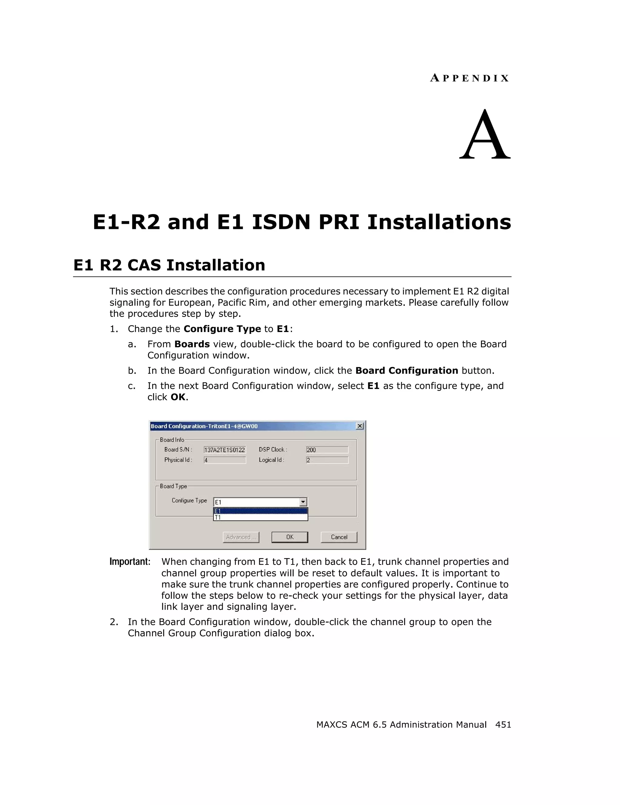
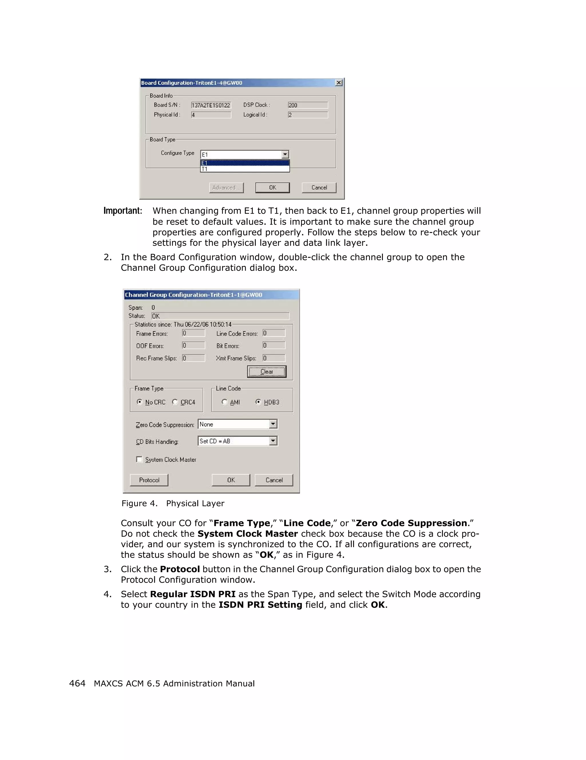
E1 ISDN PRI Installation
This section describes the configuration procedures necessary to implement E1 ISDN PRI
signaling for European, Pacific Rim, and other emerging markets. Please carefully follow
the procedures step by step.
1. Change the Configure Type to E1:
a. From Boards view, double-click the board to be configured to open the Board
Configuration window.
b. In the Board Configuration window, click the Board Configuration button.
c. In the next Board Configuration window, select E1 as the configure type, and
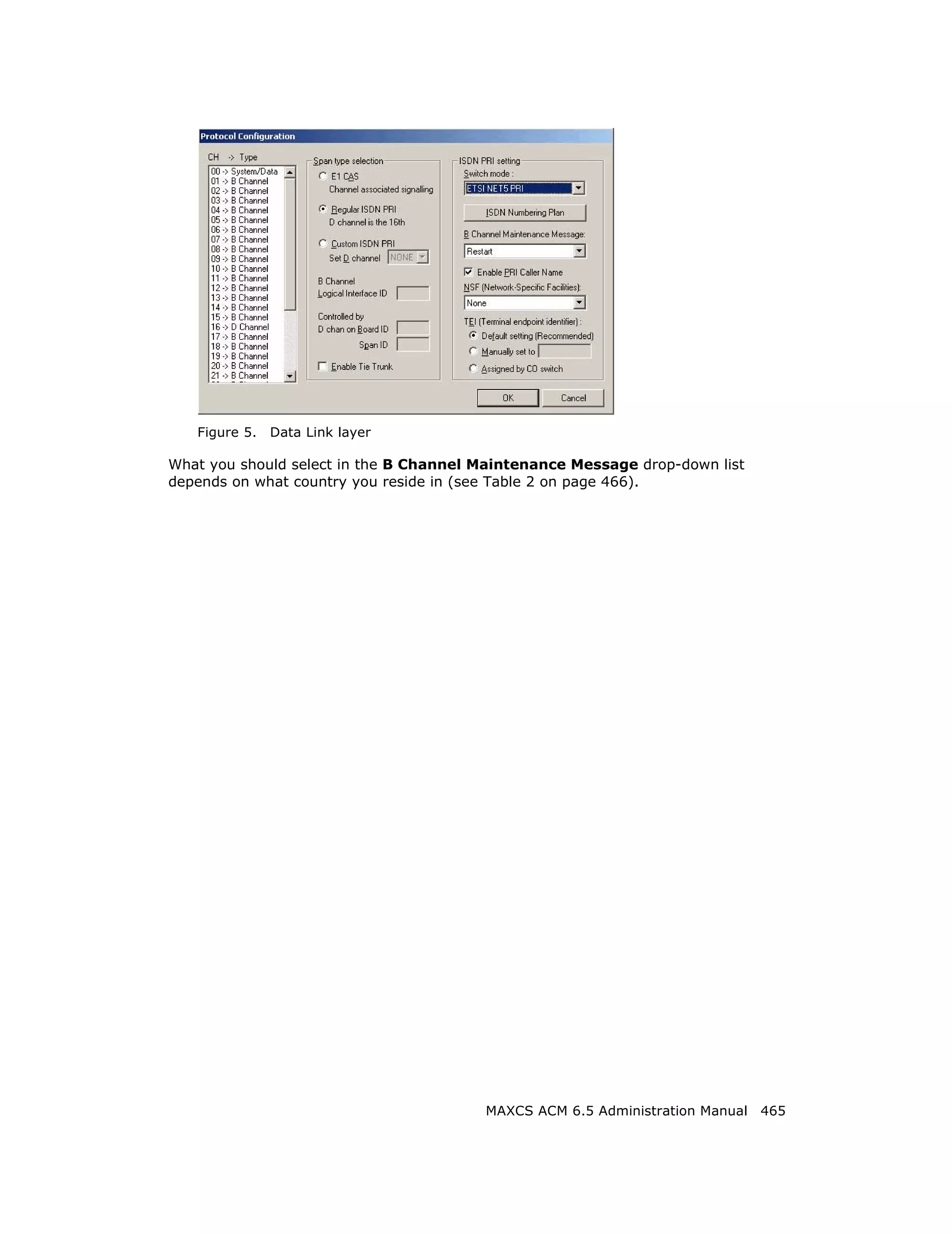
click OK.
MAXCS ACM 6.5 Administration Manual 463](https://image.slidesharecdn.com/maxcsacm6-5administrationmanual-100910152521-phpapp02/75/AltiGen-M-A-X-C-S-A-C-M-6-477-2048.jpg)


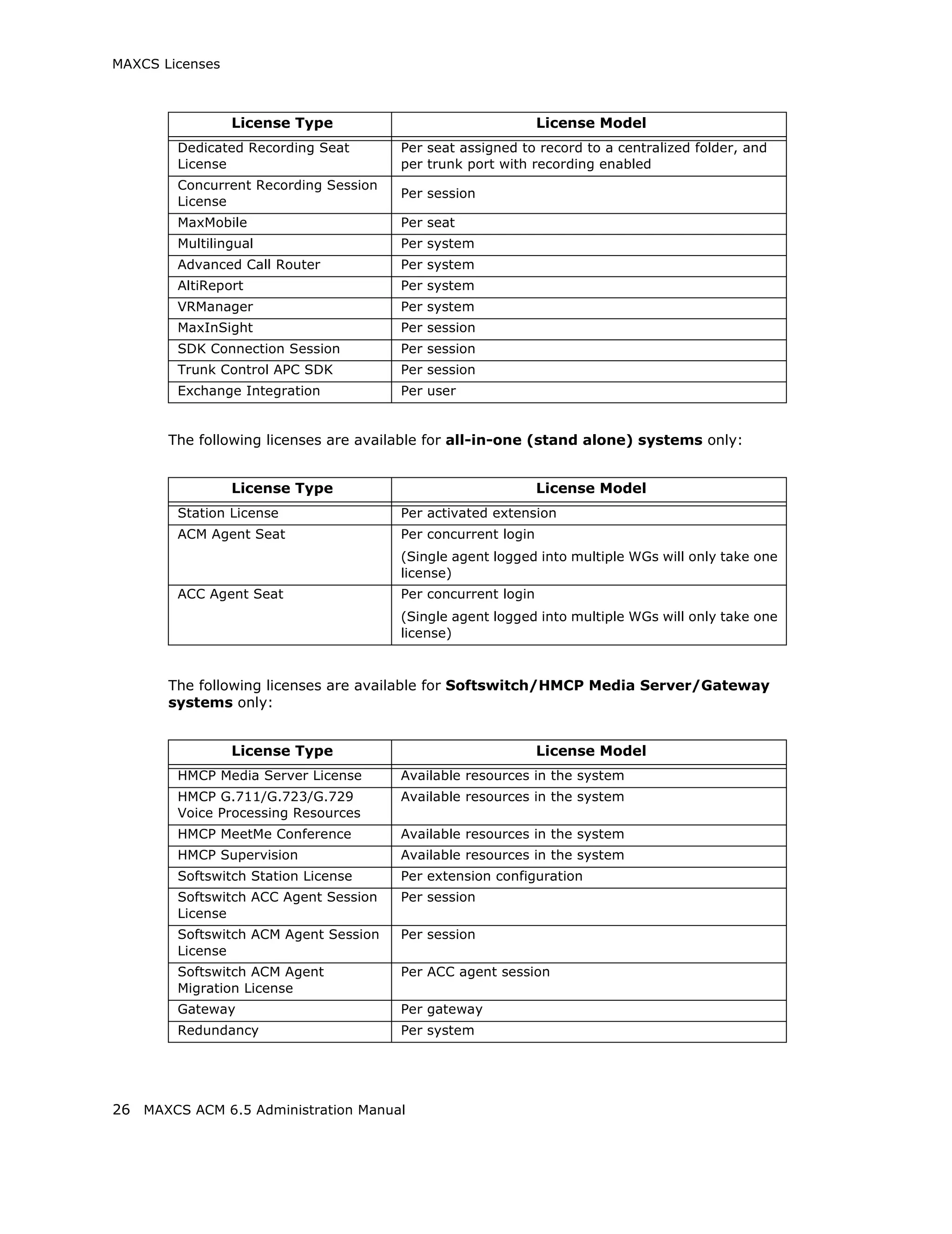
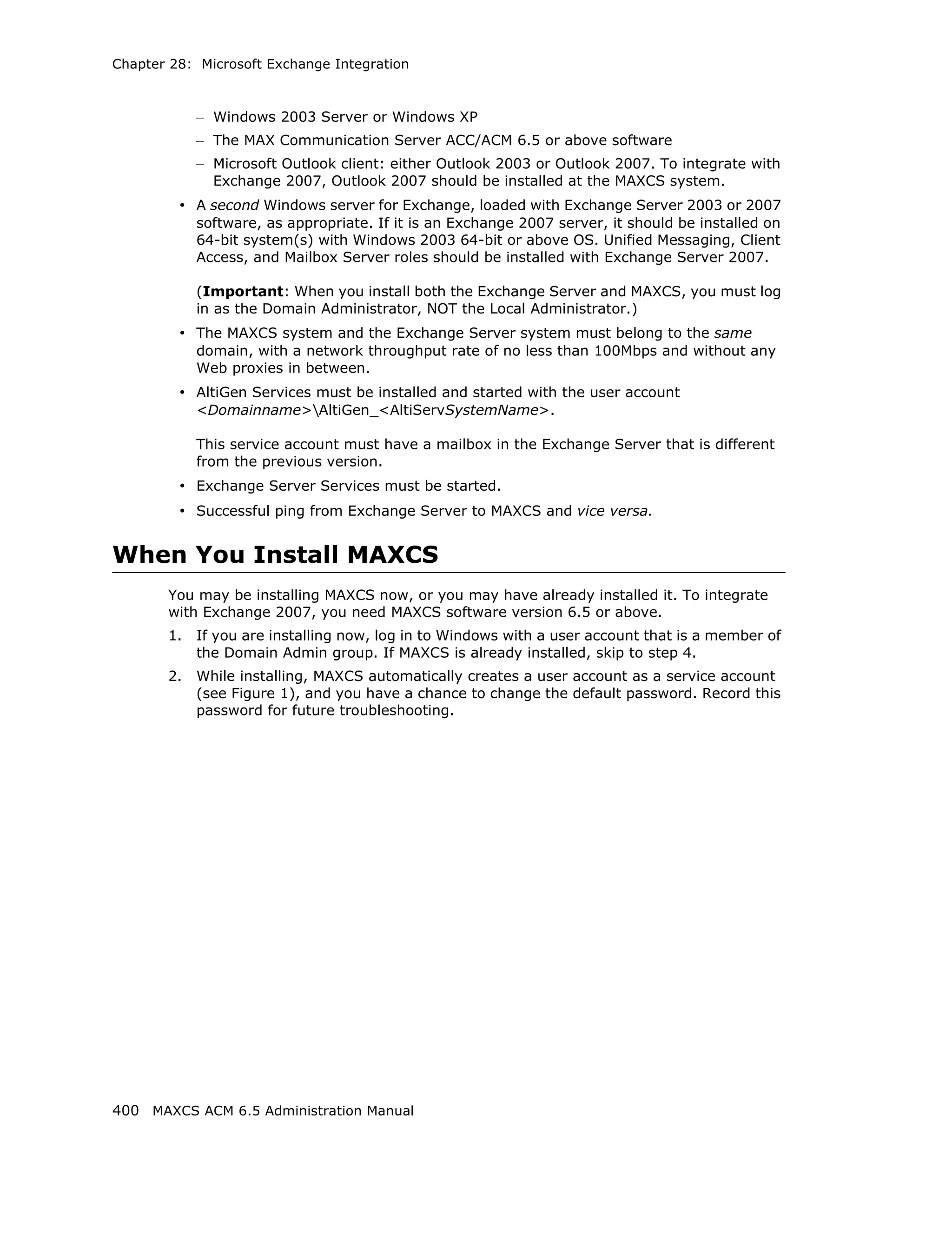
This document is the administration manual for Max Communication Server ACM 6.5 Update 1, detailing system features, installation requirements, and configuration guidance. It warns of toll fraud and emphasizes the importance of implementing security measures and practices by users. The document also lists trademarks and contains patent information related to Altigen Communications, Inc.


![Vibe Coding vs. Spec-Driven Development [Free Meetup]](https://cdn.slidesharecdn.com/ss_thumbnails/vibecodingvsspecdrivendevelopment-251209105622-43f455e7-thumbnail.jpg?width=640&height=640&fit=bounds)


