This document is a user manual for PowerFlex 20-HIM-A6 and 20-HIM-C6S Human Interface Modules (HIMs). It contains important safety information and guidelines for installing, operating, and maintaining the HIMs. The manual provides details on HIM components, screen displays, and instructions for common tasks like parameter editing, fault viewing, and firmware updating. It also includes specifications for the HIMs' communication and electrical characteristics.


![Rockwell Automation Publication 20HIM-UM001D-EN-P - February 2013 9
Preface
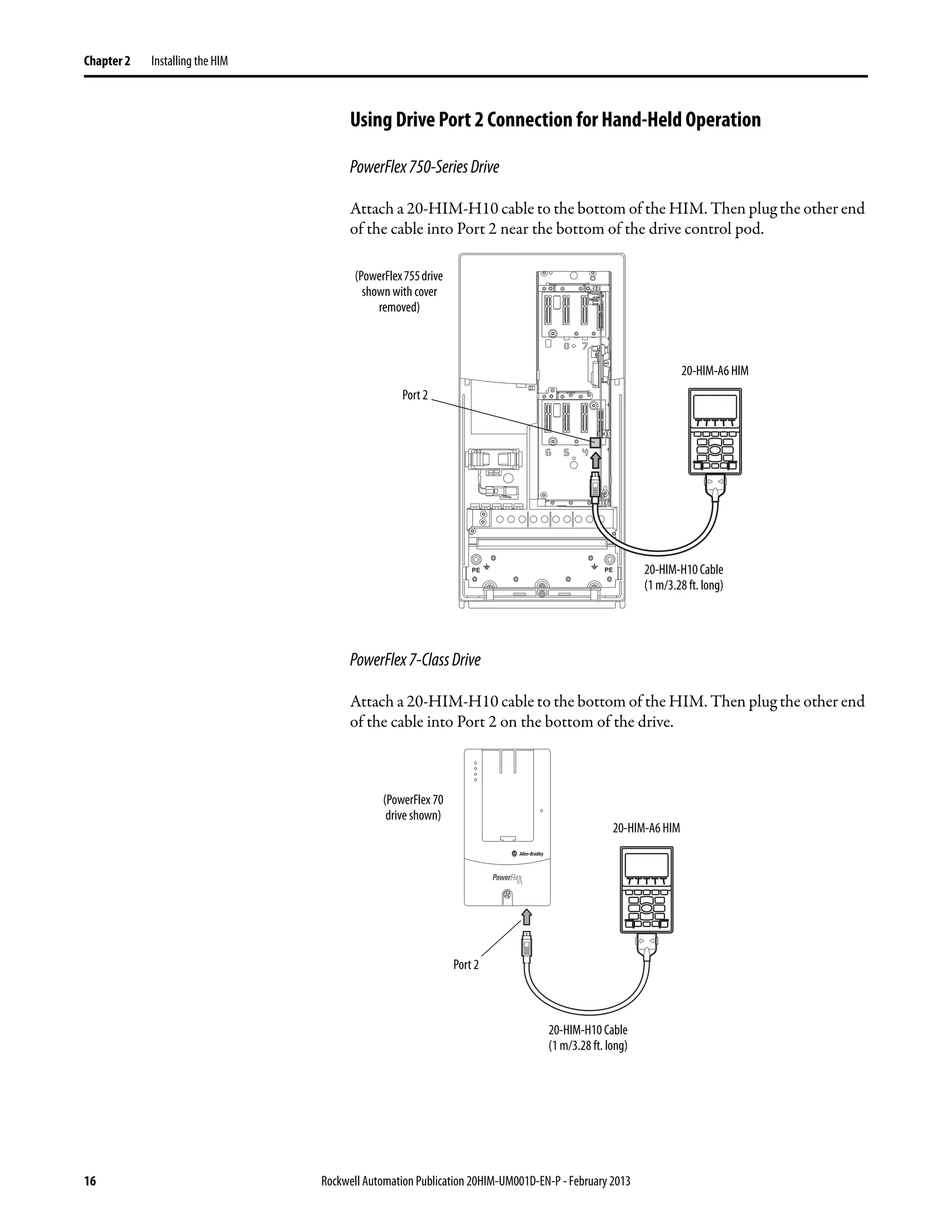
This manual provides information about the enhanced PowerFlex 20-HIM-A6
and 20-HIM-C6S Human Interface Modules, and using them with PowerFlex
750-Series drives and PowerFlex® 7-Class drives.
Conventions Used in This
Manual
The following conventions are used throughout this manual:
• Parameter names are shown in the format Parameter xx - [*]. The xx
represents the parameter number. The * represents the parameter name—
for example Parameter 01 - [Port Number].
• The HIM or drive firmware revision number (FRN) is displayed as FRN
X.xxx, where ‘X’ is the major revision number and ‘xxx’ is the minor
revision number.
Rockwell Automation
Support
Rockwell Automation offers support services worldwide, with over 75 sales and
support offices, over 500 authorized distributors, and over 250 authorized
systems integrators located through the United States alone. In addition,
Rockwell Automation representatives are in every major country in the world.
Local Product Support
Contact your local Rockwell Automation representative for the following:
• Sales and order support
• Product technical training
• Warranty support
• Support service agreements
Technical Product Assistance
For technical assistance, please review the information in Chapter 4, Using the
HIM, first. If you still have problems, then access the Allen-Bradley Technical
Support website at http://www.ab.com/support/abdrives or contact Rockwell
Automation.](https://image.slidesharecdn.com/20him-um001-en-p-190930090915/75/20him-um001-en-p-9-2048.jpg)


![Rockwell Automation Publication 20HIM-UM001D-EN-P - February 2013 23
HIM Components Chapter 3
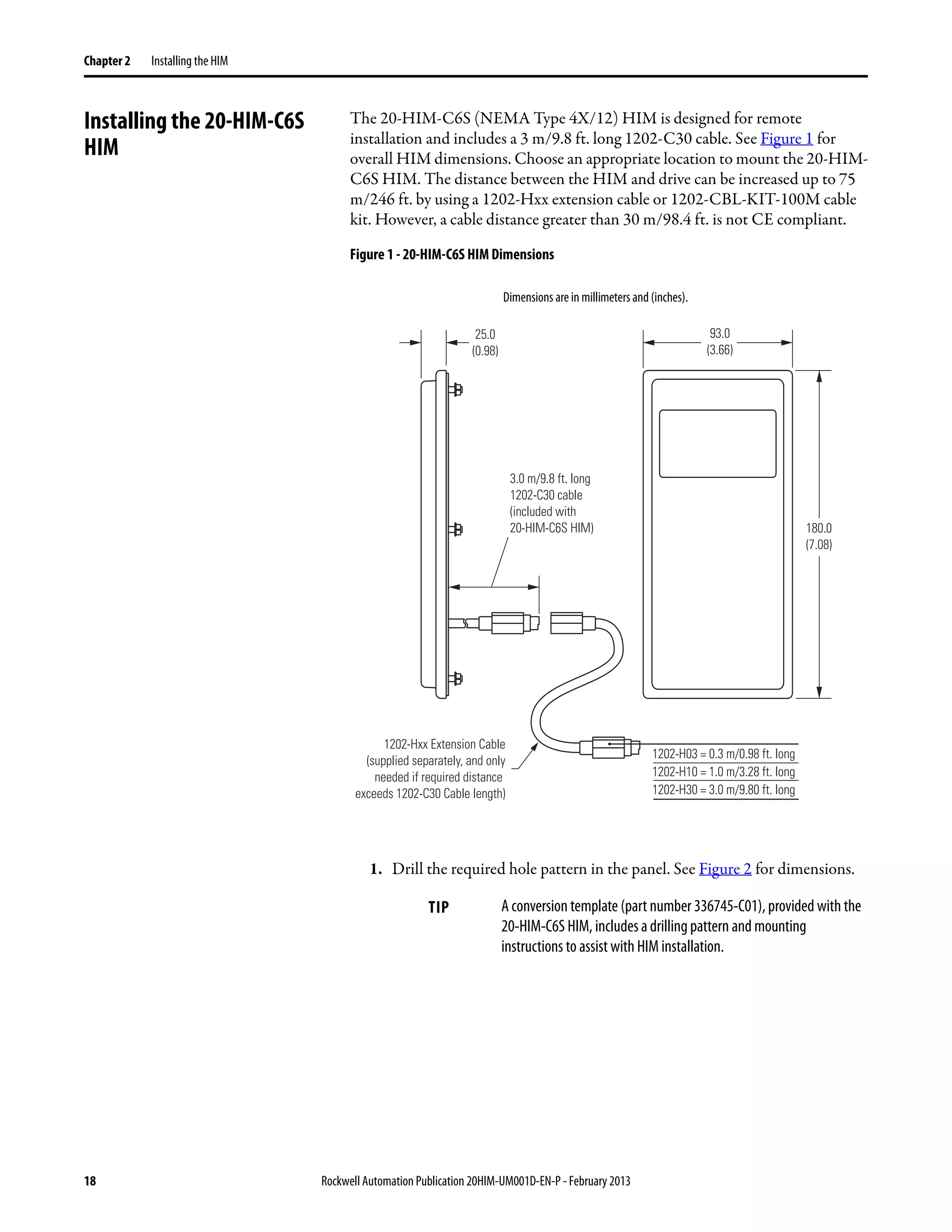
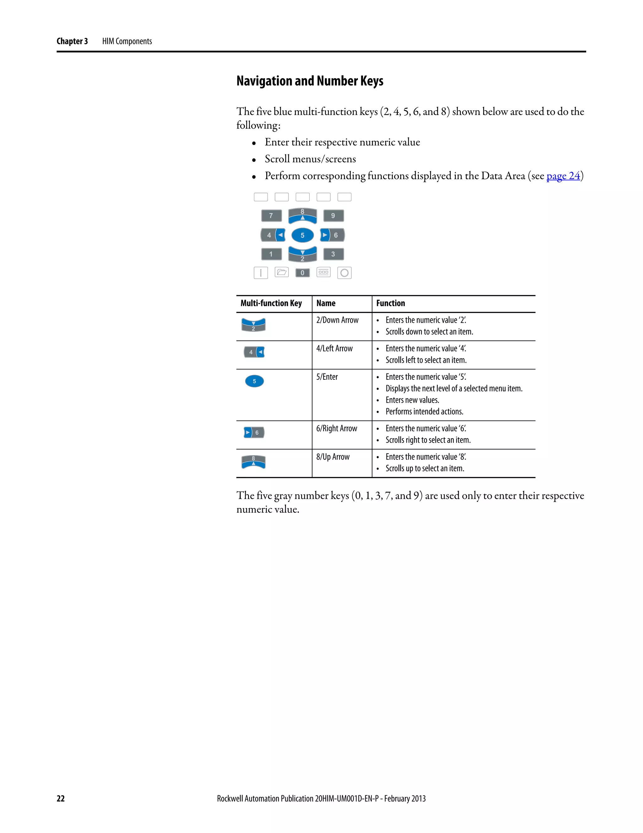
Single-function Keys
There are four single-function keys, which are highlighted below and listed in the
table below. Each single-function key always performs only its dedicated
function.
Single-function Key Name Function
Start Starts the drive.
(1)
(1) During drive Start Up these keys are temporarily inactive.
Folders Accesses folders for parameters, diagnostics, memory functions,
preferences, and other tasks.
(1) Controls Accesses jog, direction, auto/manual, andother control functions.
Stop • Stops the drive or clears a fault.
• This key is always active.
• This key is controlled by drive parameter 307 [Start Stop Mode].](https://image.slidesharecdn.com/20him-um001-en-p-190930090915/75/20him-um001-en-p-23-2048.jpg)


![Rockwell Automation Publication 20HIM-UM001D-EN-P - February 2013 27
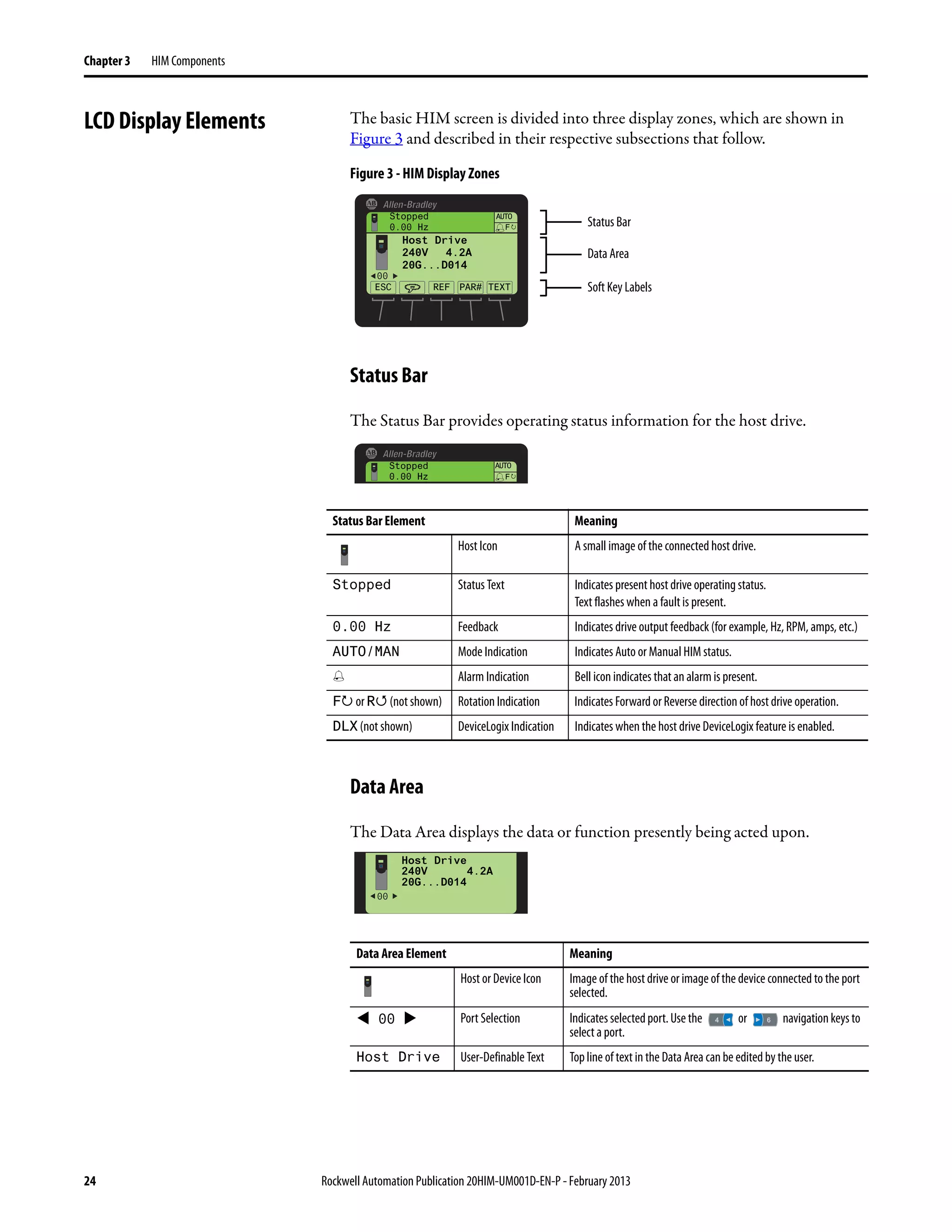
HIM Components Chapter 3
StatusScreenSoftKeys
StatusScreenNavigation/NumberKeys
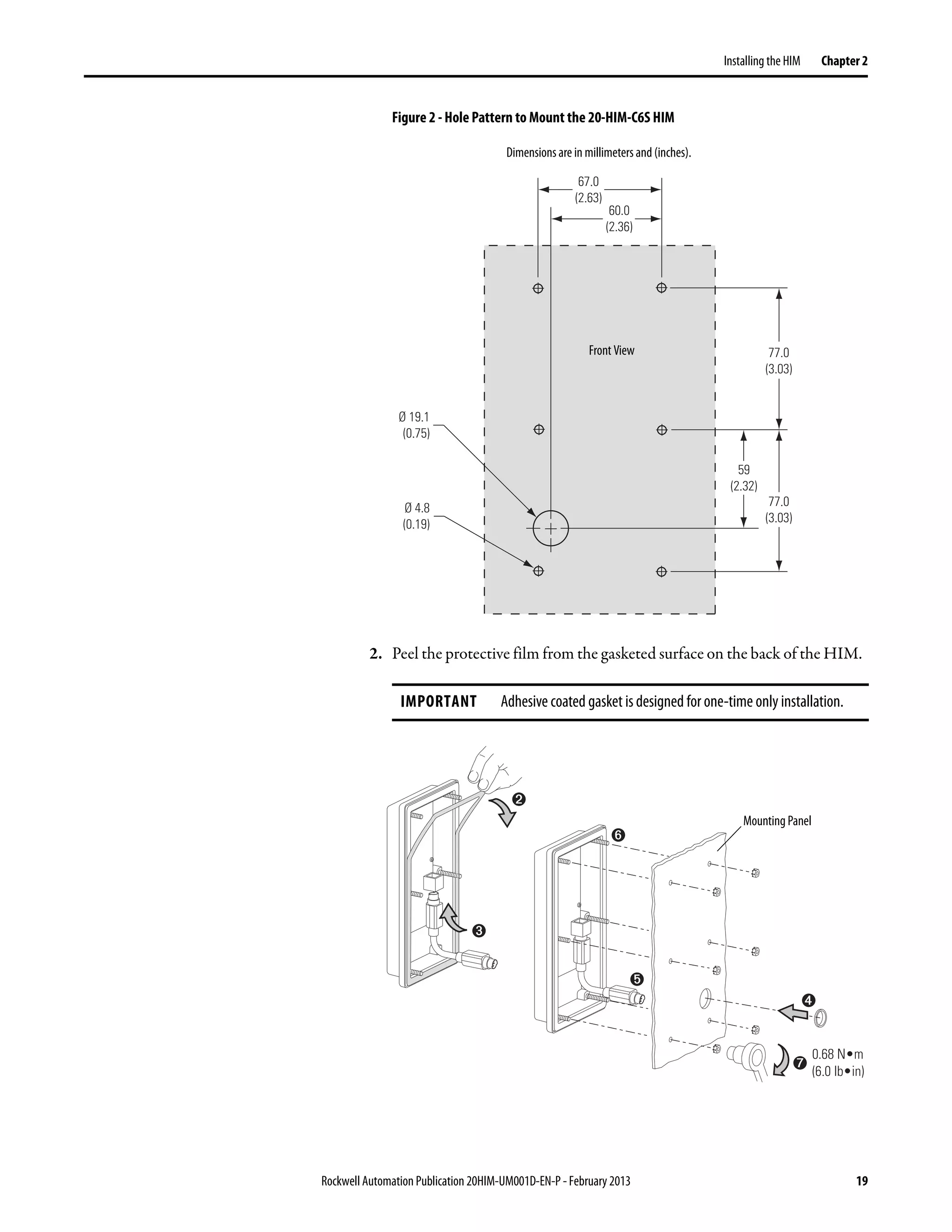
If you would rather see the Process screen (shown below) as the initial power-up
screen, change the HIM Parameter 03 - [Initial Screen] value to ‘1’ (Process
Scrn). By default, when the HIM keys are not used for the time period set in
Parameter 07 - [User Dspy Time], the screen being displayed at that time will
revert back to the initial screen. You can disable this feature by setting Parameter
06 - [User Dspy Enable] to ‘1’ (Disable).
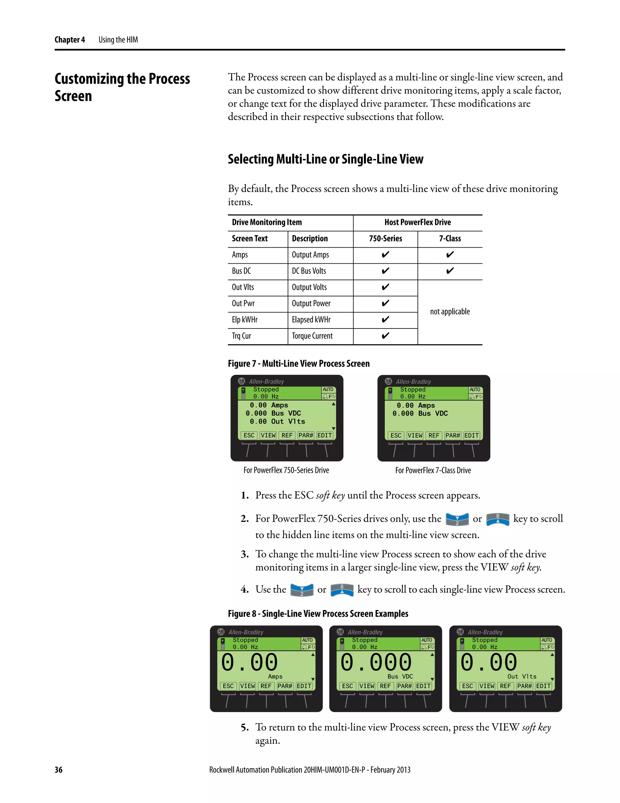
Process Screen
To display the Process screen, press the ESC soft key on the Status screen
(Figure 4). The Process screen shows various drive monitoring parameters. Multi-
line and Single-line views can be selected by pressing the VIEW soft key. The
displayed default monitoring parameters can be changed. See Customizing the
Process Screen on page 36 for details.
ProcessScreenSoftKeys
Label Name Function
ESC Escape Toggles between the Status and Process Display screens.
Language Icon Directly accesses the Select Language To Use screen.
REF Reference Enters the speed reference for the Host Drive.
PAR# Parameter Number Directly accesses a parameter for the device on selected port. (This soft key is
not available if the device has no parameters.)
TEXT Text Edits user-definable text for the device on selected port.
Key Name Function Screen Element
4/Left Arrow Selects the device on previous port.
6/Right Arrow Selects the device on next port.
Label Name Function
ESC Escape Toggles between the Process Display and Status screens.
VIEW View Toggles between the multi-line and single-line views.
REF Reference Enters the speed reference for the Host Drive.
PAR# Parameter Number Directly accesses a parameter for the selected port device.
EDIT Edit Directly accesses the Edit Process Display screen.
00
Stopped
0.00 Hz
AUTO
0.00
0.000
0.00
VIEW
F
REF PAR#
Amps
Bus VDC
Out Vlts
EDITESC](https://image.slidesharecdn.com/20him-um001-en-p-190930090915/75/20him-um001-en-p-27-2048.jpg)


![Rockwell Automation Publication 20HIM-UM001D-EN-P - February 2013 35
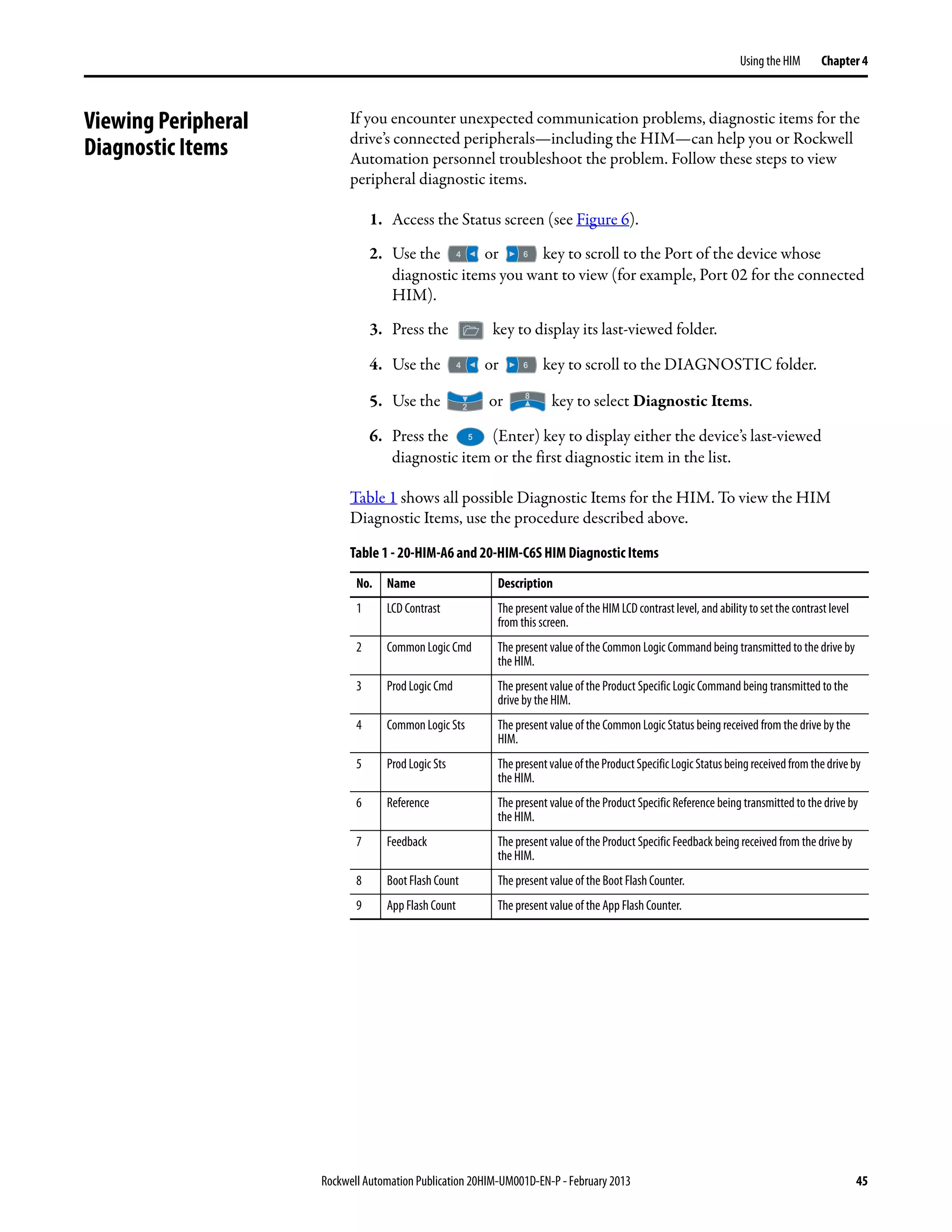
Using the HIM Chapter 4
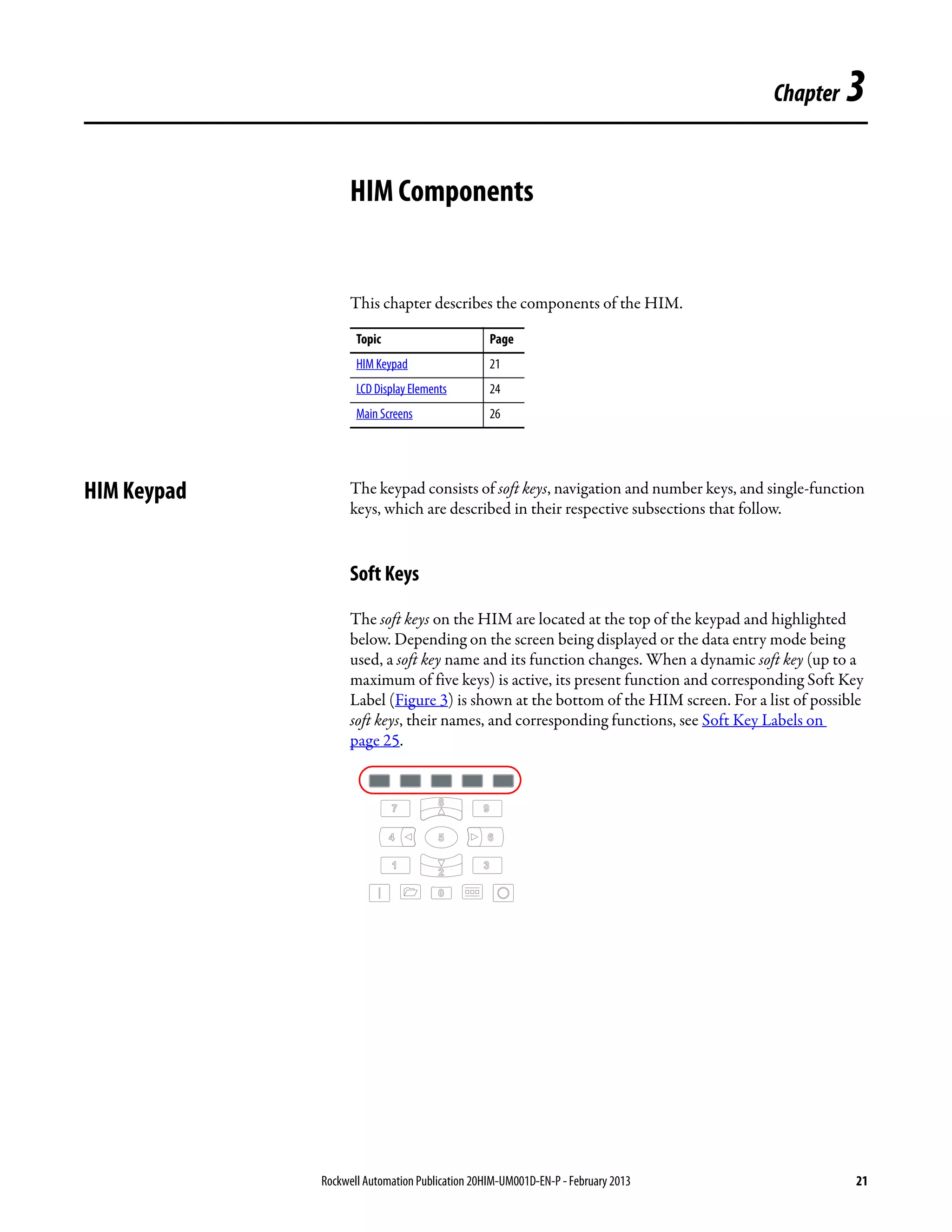
Creating a User-Defined
Drive/Peripheral Name
The host drive and each of its connected peripherals has a default name. You can
change any of these default names, but each new user-defined name cannot
exceed 16 characters in length. Follow these steps to change a default name.
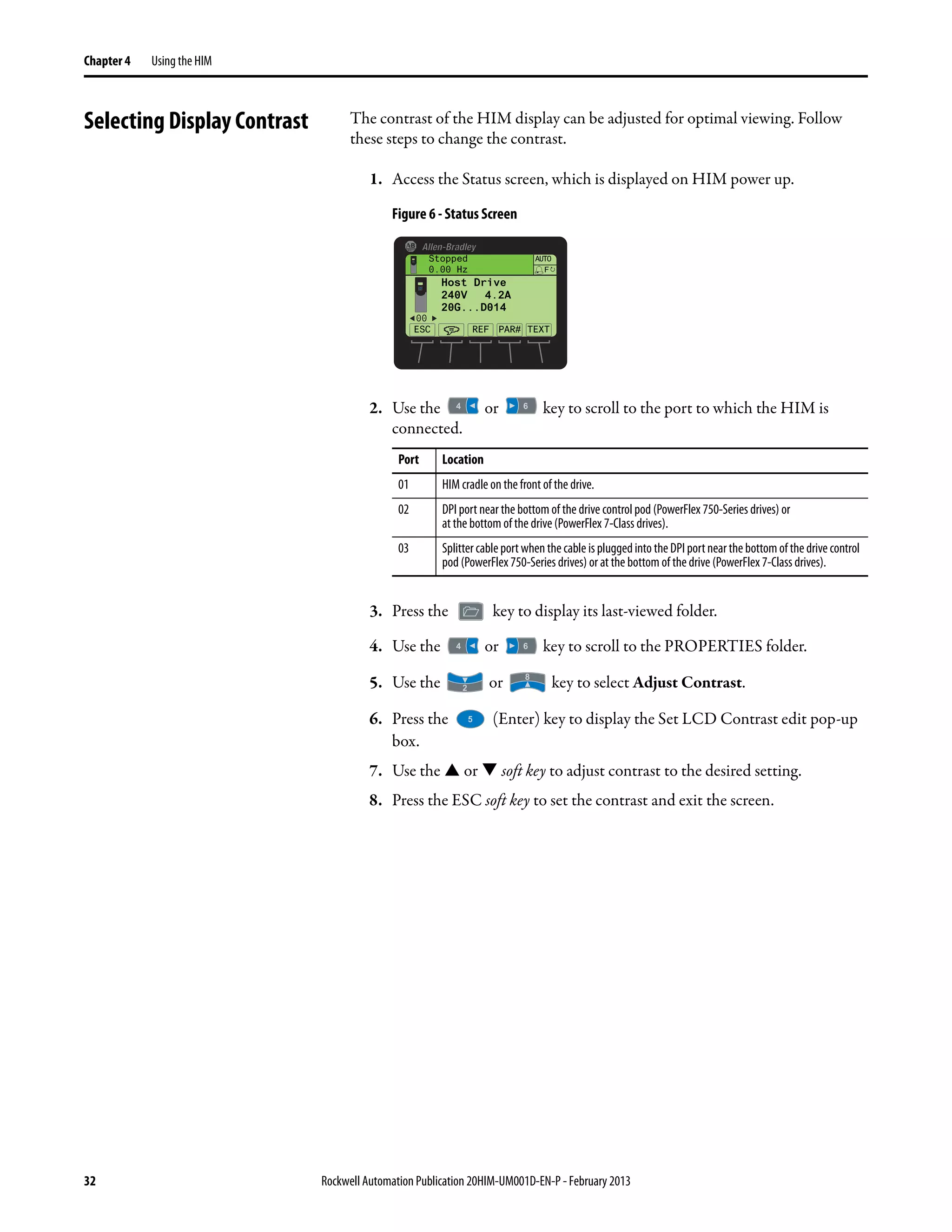
1. Access the Status screen (see Figure 6).
2. Use the or key to scroll to the Port of the device whose name
you want to change (for example, Port 00 for the host drive).
3. Press the TEXT soft key to display the Edit User Defined Text pop-up box.
4. Use the or key to move the cursor to the desired character
position in the displayed name.
5. Press the key to access the last-viewed character set.
6. Press the appropriate numeric key to access the desired character set.
Also, use the appropriate soft keys to help create the new name.
7. With the desired character selected in that character position, press the
key to select and enter the character.
8. Repeat steps 4 through 7 for each character position.
9. When the desired name is displayed on the edit pop-up box, press the
ENTER soft key to enter and save the new name.
IMPORTANT Text editing is not supported when using Asian language characters. Only
characters in the ISO 8859-1 Latin 1 Character Set, which is supported by U.S.
and European personal computers, are available. If a software tool is used for
text editing Asian characters, the HIM will replace all unsupported characters
with a [] (narrow rectangle) mark.
Numeric Key Function
Selects the numeric character set.
Selects the symbols character set.
Selects the upper case letter character set.
Selects the lower case letter character set.
Soft Key Function
DEL Deletes a highlighted character.
INS Inserts a space to the left of a highlightedcharacter.
CLR Deletes an entire text string.
ESC ENTER
Stopped
0.00 Hz
AUTO
F
INS DEL
, =Move Cursor =Char Set
CLR
Edit User Defined Text
PowerFlex 755](https://image.slidesharecdn.com/20him-um001-en-p-190930090915/75/20him-um001-en-p-35-2048.jpg)


![40 Rockwell Automation Publication 20HIM-UM001D-EN-P - February 2013
Chapter 4 Using the HIM
Setting Display Flashing for
Fault Indication
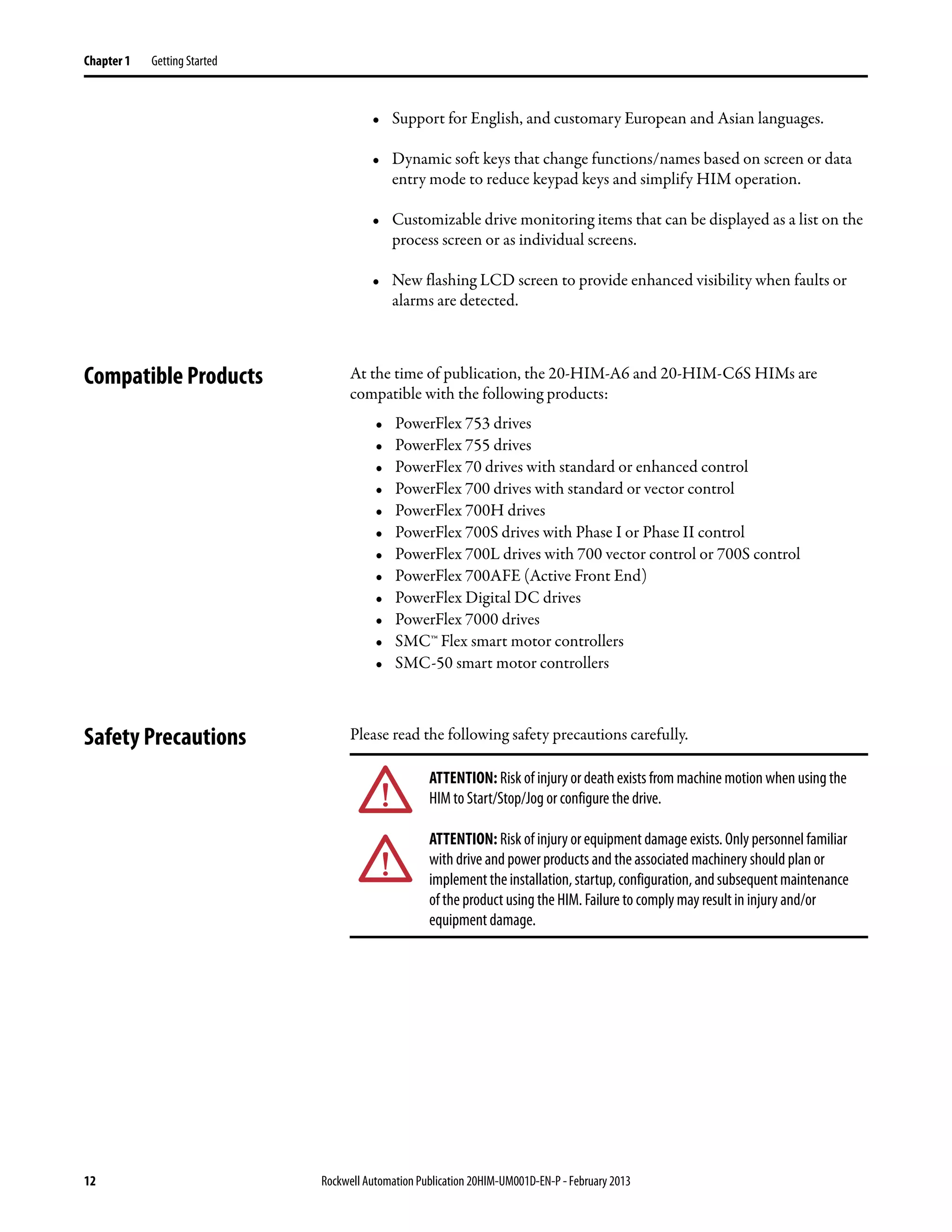
Whenever a fault for the host drive or any of its connected peripherals is
detected, a pop-up Fault Display screen (see page 30) appears. By default, only
the Status Bar flashes to alert the operator. However, you can change the flash
mode for the Fault Display screen to one of the following modes:
• Flash Bklite; selects the entire LCD screen to flash.
• Flash Status (default); selects only the Status Bar (item 1, Figure 3) to flash.
• Flash None; selects no flashing for the Fault Display screen.
Follow these steps to change the flash mode for the Fault Display screen.
1. Access HIM Parameter 04 - [Fault Dspy Type] using either the Direct
Parameter Access method (page 42) or Alternate Linear List method
(page 43).
2. Press the EDIT soft key to display the Edit Fault Dspy Type pop-up box.
3. Use the and soft keys to select the desired flash mode. To delete an
erroneous entry, use the soft key.
4. Press the ENTER soft key to enter your selection and return to the
parameter screen.
ESC ENTER
Stopped
0.00 Hz
AUTO
F
▲ ▼
Edit Fault Dspy Type
Flash Bklite 0
0 << 2](https://image.slidesharecdn.com/20him-um001-en-p-190930090915/75/20him-um001-en-p-40-2048.jpg)
![Rockwell Automation Publication 20HIM-UM001D-EN-P - February 2013 41
Using the HIM Chapter 4
Setting Display Flashing for
Alarm Indication
Whenever an alarm for the Host Drive is detected, an alarm bell icon appears in
the Status Bar. By default, only the Status Bar flashes to alert the operator.
However, you can change the flash mode for alarm indication to one of the
following modes:
• Flash Bklite; selects the entire LCD screen to flash.
• Flash Status (default); selects only the Status Bar (item 1, Figure 3) to flash.
• Flash None; selects no flashing for alarm indication.
Follow these steps to change the flash mode for alarm indication.
1. Access HIM Parameter 05 - [Alarm Dspy Type] using either the Direct
Parameter Access method (page 42) or Alternate Linear List method
(page 43).
2. Press the EDIT soft key to display the Edit Alarm Dspy Type pop-up box.
3. Use the and soft keys to select the desired flash mode.
To delete an incorrect entry, use the soft key.
4. Press the ENTER soft key to enter your selection and return to the
parameter screen.
ESC ENTER
Stopped
0.00 Hz
AUTO
F
▲ ▼
Edit Alarm Dspy Type
Flash Status 1
0 << 2](https://image.slidesharecdn.com/20him-um001-en-p-190930090915/75/20him-um001-en-p-41-2048.jpg)


![Rockwell Automation Publication 20HIM-UM001D-EN-P - February 2013 49
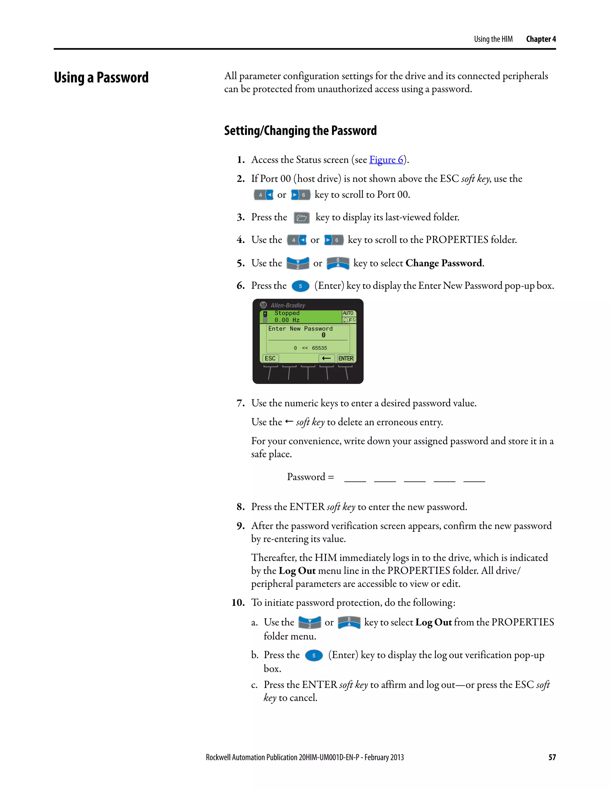
Using the HIM Chapter 4
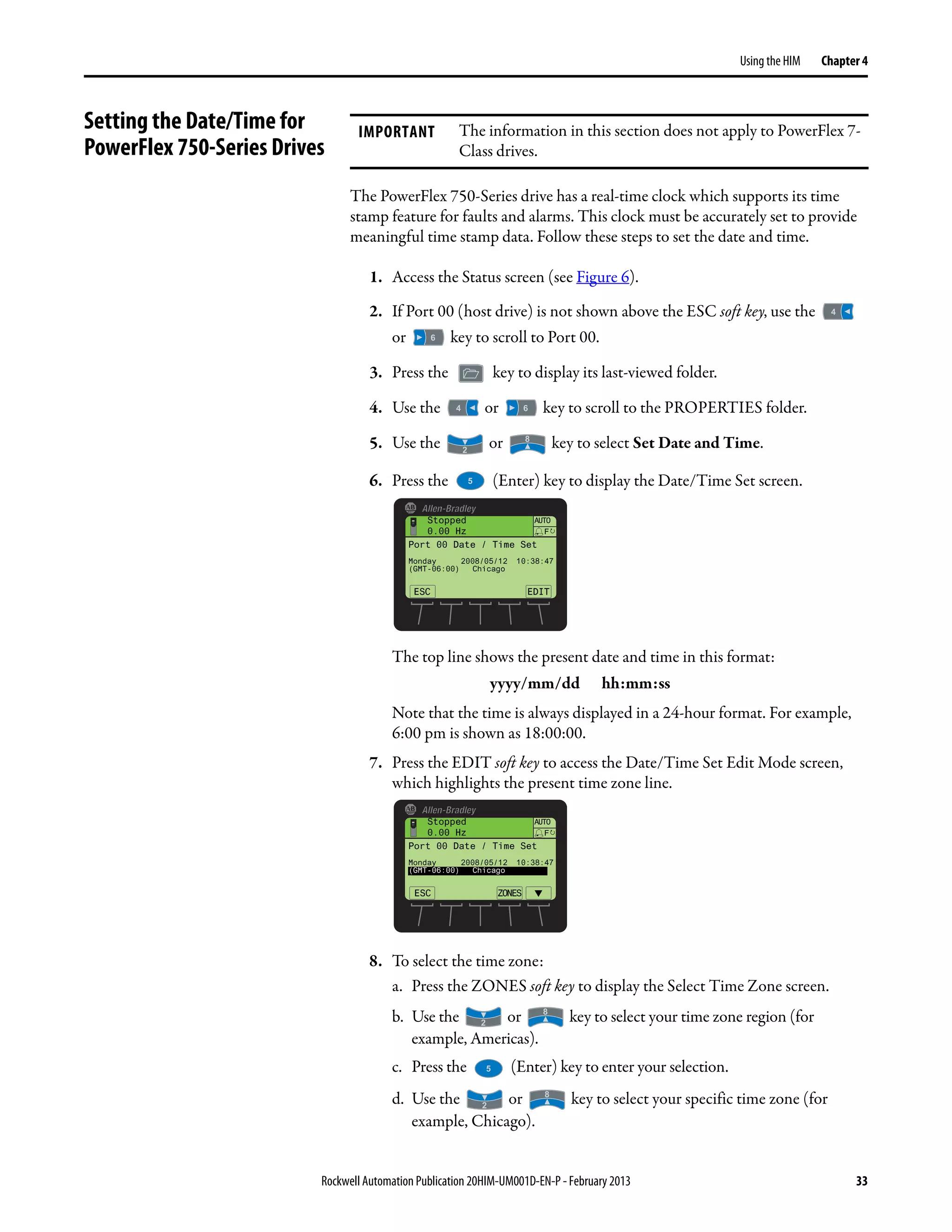
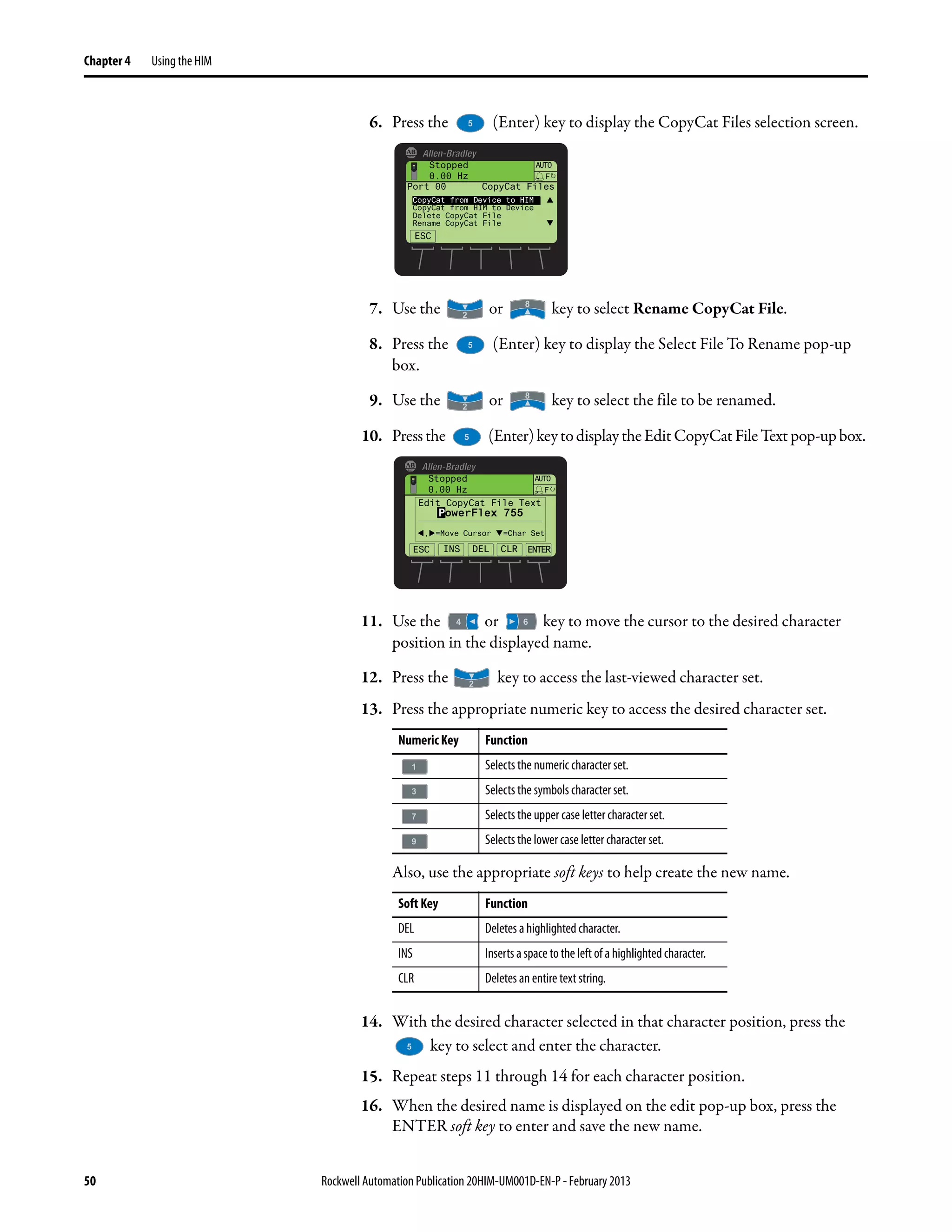
6. Press the (Enter) key to display the CopyCat Files selection screen.
7. Use the or key to select the appropriate action and press the
(Enter) key to initiate that action.
8. With New File selected on the Select Upload File screen, press the
(Enter) key to create the file. A pop-up box will appear to confirm that the
CopyCat file was successfully created. Press the ENTER soft key to
complete the procedure.
When selecting an item row that is an existing CopyCat file—not a ‘New
File’ row—to create a new CopyCat file, an Overwrite pop-up box will
appear. Press the ENTER soft key to affirm and overwrite the existing
CopyCat file—or press the ESC soft key to cancel.
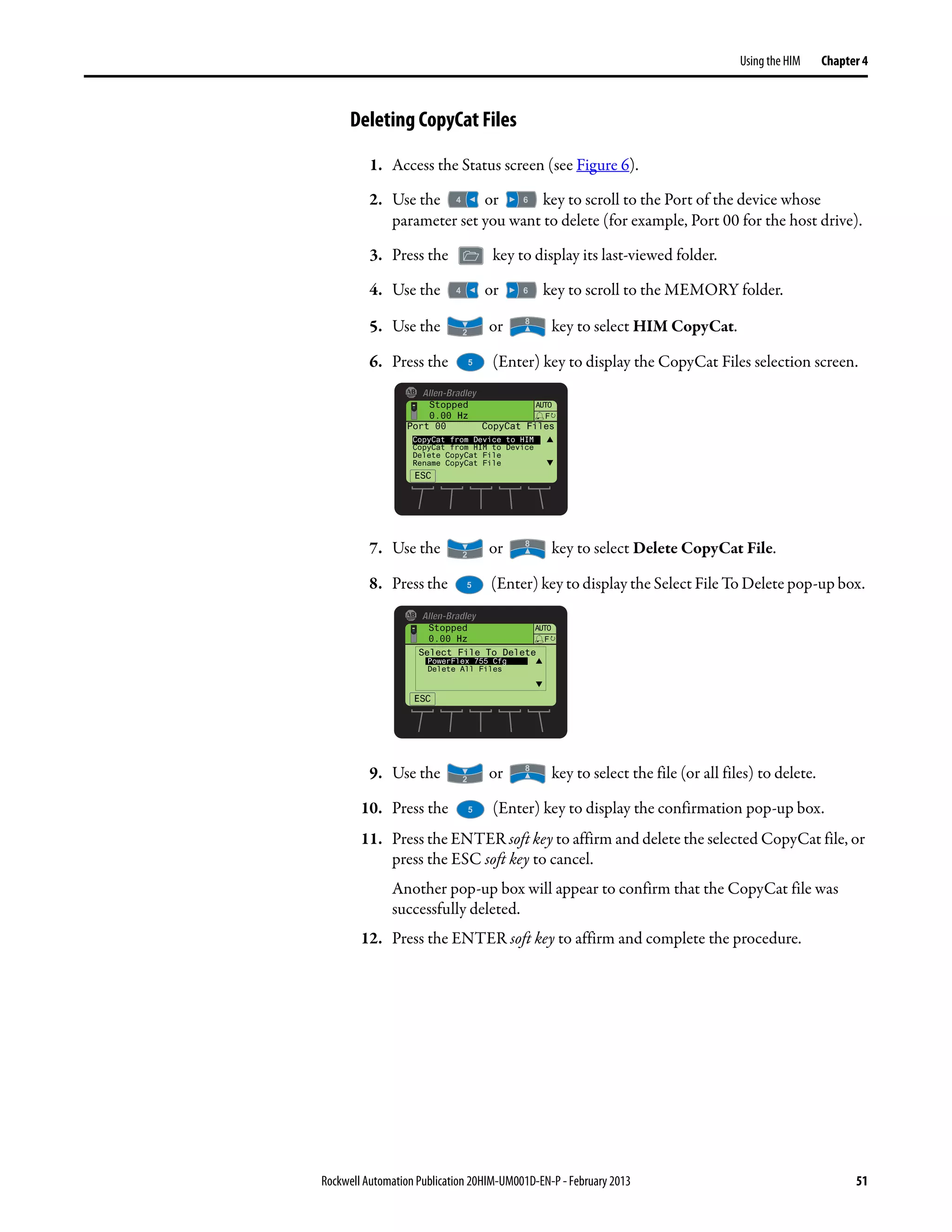
Renaming CopyCat Files
1. Access the Status screen (see Figure 6).
2. Use the or key to scroll to the Port of the device whose
CopyCat file you want to rename (for example, Port 00 for the host drive).
3. Press the key to display its last-viewed folder.
4. Use the or key to scroll to the MEMORY folder.
5. Use the or key to select HIM CopyCat.
TIP Before any CopyCat filesare created, only the ‘CopyCat From Device to
HIM’ menu item is shown. When Port 00 for the Host Drive is selected
in Step 2, the ‘Upload All Ports’ menu item also appears.
TIP When aCopyCatfile is created,itsdefaultfile namecorrespondsto the
device whose file is being copied. For example, a newly created
CopyCat file for a PowerFlex 755 drive has a default file name of
‘PowerFlex 755’.
IMPORTANT Text editing is not supported when using Asian language characters. Only
characters in the ISO 8859-1 Latin 1 Character Set, which is supported by U.S.
and European personal computers, are available. If a software tool is used for
text editing Asian characters, the HIM will replace all unsupported characters
with a [] (narrow rectangle) mark.
Stopped
0.00 Hz
AUTO
ESC
F
Port 00 CopyCat Files
CopyCat from Device to HIM
CopyCat from HIM to Device
Delete CopyCat File
Rename CopyCat File](https://image.slidesharecdn.com/20him-um001-en-p-190930090915/75/20him-um001-en-p-49-2048.jpg)
![52 Rockwell Automation Publication 20HIM-UM001D-EN-P - February 2013
Chapter 4 Using the HIM
Changing PowerFlex 750-
Series Drive Parameter
Associations
PowerFlex 750-Series drives have special parameters (indirect selector parameters
and reference parameters) which are always associated with other parameters.
The values for these special parameters are actually pointers to other parameters
in the drive or to Host parameters in connected peripherals. To change a
parameter association, first access the indirect selector or reference parameter.
Second, select the port number of the device whose parameter you want to target
for association. Then, select the target parameter of that device. If the target
parameter is a bit parameter, you must also select the appropriate bit you want to
associate with the indirect selector or reference parameter.
Parameter associations can be changed using one of these methods:
• Individual Screen Entry Method—where individual pop-up screens are
used to enter the required parameter association data.
• Direct Numeric Entry Method—where the required parameter association
data is entered as a number string on a single pop-up screen.
The following example illustrates how to use each method to change a parameter
association. Suppose you want the drive speed reference to come from the
network controller via the embedded EtherNet/IP adapter on the Main Control
Board in a PowerFlex 755 drive.
Using Individual Screen Entry Method
1. Access the indirect selector or reference parameter whose association you
want to change (for this example, drive Parameter 545 - [Spd Ref A Sel] as
shown below).
In this example, the Port field is shown selected. Use the or
key to select the Port, Parameter, or Bit (if applicable) fields.
TIP Depending on the indirect selector or reference parameter selected,
you may see more available ports in the list.
ESC EDIT
Stopped
0.00 Hz
AUTO
F
#
Port 00 Dev Param 545
Spd Ref A Sel
P00 P0871
Port PowerFlex 755
PAR#](https://image.slidesharecdn.com/20him-um001-en-p-190930090915/75/20him-um001-en-p-52-2048.jpg)
![Rockwell Automation Publication 20HIM-UM001D-EN-P - February 2013 53
Using the HIM Chapter 4
2. Press the EDIT soft key to display the edit pop-up box for the selected field
(in this case, the port number field).
3. Use the or key to scroll to the port number of the device
whose parameter you want to target for the association (for this example,
Port 00, where the speed Reference parameters for the available drive ports
are located).
4. Press the ENTER soft key to enter the selected port number.
The target parameter selection pop-up box appears (see example screen
below), showing a list of available target parameters that can be associated.
5. Use the or key to scroll to the target parameter you want to
associate.
For this example, we selected drive Parameter 877 - [Port 13 Reference]).
6. Press the ENTER soft key to enter the selected target parameter.
If the target parameter:
• Is not a bit parameter, the parameter association is now changed and
the indirect selector or reference parameter screen re-appears with the
associated parameter information shown.
• Is a bit parameter, a list of available bit numbers is displayed. Use the
or key to scroll to the bit number of the target parameter
you want to associate, and press the ENTER soft key. The parameter
TIP The ‘Zero Speed’ setting may be available to select for specific
applications that require a safe-state speed Reference.
Stopped
0.00 Hz
AUTO
F
Edit Spd Ref A Sel
Select Port To Use
Zero Speed
Port 00 PowerFlex755
ESC ENTER
Stopped
0.00 Hz
AUTO
F
Edit Spd Ref A Sel
Select Param To Use
Par 0546 Spd Ref A Stpt
Par 0571 Preset Speed 1
Par 0572 Preset Speed 2
ESC ENTER
ESC EDIT
Stopped
0.00 Hz
AUTO
F
#
Port 00 Dev Param 545
Spd Ref A Sel
P00 P0871
Port PowerFlex 755
PAR#](https://image.slidesharecdn.com/20him-um001-en-p-190930090915/75/20him-um001-en-p-53-2048.jpg)
![54 Rockwell Automation Publication 20HIM-UM001D-EN-P - February 2013
Chapter 4 Using the HIM
association is now changed and the indirect selector or reference
parameter screen re-appears with the associated parameter information
shown.
Using Direct Numeric Entry Method
1. Access the indirect selector or reference parameter whose association you
want to change (for this example, drive Parameter 545 - [Spd Ref A Sel] as
shown below).
2. With any field (port, parameter, or bit) selected, press the # soft key to
display the Direct Numeric Entry pop-up box.
3. Use the numeric keys to enter a number string that represents the target
parameter’s device port number, parameter number and, only when the
target parameter is a bit parameter, its bit number.
The number string format is PPpppp.bb, where:
PP = device port number
pppp = target parameter number
bb = bit number (only used when target parameter is a bit parameter)
4. Press the ENTER soft key to enter the number string and complete the
parameter association.
The indirect selector or reference parameter screen re-appears with the
associated parameter information.
ESC EDIT
Stopped
0.00 Hz
AUTO
F
#
Port 00 Dev Param 545
Spd Ref A Sel
P00 P0871
Port PowerFlex 755
PAR#
ESC EDIT
Stopped
0.00 Hz
AUTO
F
#
Port 00 Dev Param 545
Spd Ref A Sel
P00 P0871
Port PowerFlex 755
PAR#
Stopped
0.00 Hz
AUTO
F
Edit Spd Ref A Sel
871
0 << 159999
ESC ENTER](https://image.slidesharecdn.com/20him-um001-en-p-190930090915/75/20him-um001-en-p-54-2048.jpg)


![Rockwell Automation Publication 20HIM-UM001D-EN-P - February 2013 67
Appendix B
HIM Parameters
This appendix provides information about the HIM parameters.
Besides the HIM, the following configuration tools can also be used to monitor
or change parameter values of the HIM, drive, and other connected peripherals:
• Connected Components Workbench software, version 1.02 or later
• DriveExplorer software, version 6.01 or later
• DriveExecutive software, version 5.01 or later
Parameter List Parameter
No. Name and Description Details
01 [Port Number]
Displays the port on the drive to which the HIM is connected.
Minimum: 1
Maximum: 7
Type: Read Only
02 [DPI Data Rate]
DisplaystheDPIdatarateatwhichtheHIMiscommunicatingwith
the drive.
Values: 0 = 125 kbps
1 = 500 kbps
Type: Read Only
03 [Initial Screen]
Selects the initial HIM screen to be displayed on power up.
Default: 0 = Status Scrn
Value: 0 = Status Scrn
1 = Process Scrn
Type: Read/Write
Reset Required: Yes
04 [Fault Dspy Type]
Selects the type of display flash to be shown when a drive or
peripheral fault is detected.
Default: 1 = Flash Status
Values: 0 = Flash Bklite
1 = Flash Status
2 = Flash None
Type: Read/Write
Reset Required: No
05 [Alarm Dspy Type]
Selects the type of display flash to be shown when a drive alarm is
detected.
Default: 1 = Flash Status
Values: 0 = Flash Bklite
1 = Flash Status
2 = Flash None
Type: Read/Write
Reset Required: No
06 [User Dspy Enable]
Enables/disables the HIM’s automatic user display time function,
which is configured using Parameter 07 - [User Dspy Time].
Default: 1 = Enable
Values: 0 = Disable
1 = Enable
Type: Read/Write
Reset Required: Yes
07 [User Dspy Time]
Setstheamountoftimethatascreenwillremaindisplayedaslong
as the HIM keys are not used. After this time elapses, the screen is
automatically replaced by the initial screen, which is selected
using Parameter 03 - [Initial Screen].
Default: 60 sec
Minimum: 10 sec
Maximum: 300 sec
Type: Read/Write
Reset Required: Yes](https://image.slidesharecdn.com/20him-um001-en-p-190930090915/75/20him-um001-en-p-67-2048.jpg)

![Rockwell Automation Publication 20HIM-UM001D-EN-P - February 2013 69
Appendix C
History of Changes
This appendix summarizes the revisions to this manual. Reference this appendix
if you need information to determine what changes have been made across
multiple revisions. This may be especially useful if you are deciding to upgrade
your hardware or software based on information added with previous revisions of
this manual.
20HIM-UM001C-EN-P,
January 2012
This table contains the changes, which were the result of HIM firmware revision
2.001.
Topic Page
20HIM-UM001C-EN-P, January 2012 69
20HIM-UM001B-EN-P, October 2010 70
20HIM-UM001A-EN-P, January 2009 70
Topic
In Chapter 3:
• Added the Status Bar element ‘DLX’ to indicate that the Host Drive DeviceLogix feature is enabled.
• Added new softkeylabels ‘ACK’, ‘PGDN’, and ‘PGUP’ on the Device Version information screen to enhance navigation.
In Chapter 4:
• Changed the Fault Display screen flash mode default from ‘Flash Bklite’ to ‘Flash Status’.
• Added a TIP statement that holding the or soft key while using the Direct Parameter Access method to view/
edit a parameter provides continuous scrolling until the key is released.
• RevisedExample DeviceVersionInformationScreento showtheaddedsoft keylabels‘Top’,‘End’,‘PGUP’,and‘PGDN’.
In Appendix B, changed the default for Parameter 04 - [Fault Dspy Type] from ‘0’ (Flash Bklite) to ‘1’ (Flash Status).](https://image.slidesharecdn.com/20him-um001-en-p-190930090915/75/20him-um001-en-p-69-2048.jpg)


