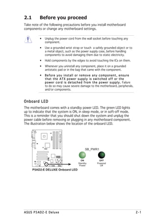
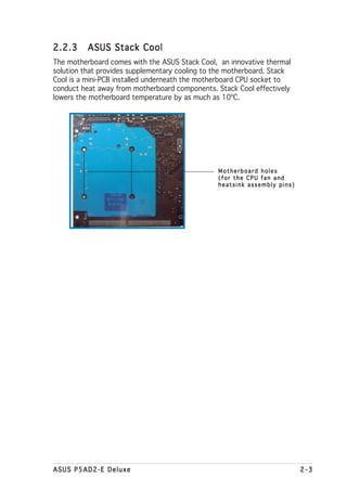
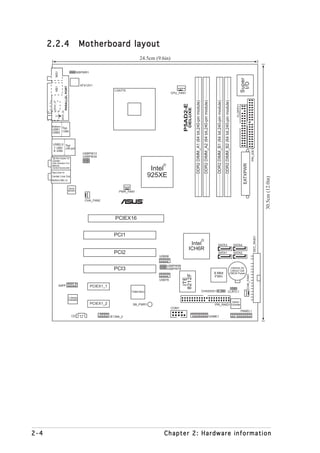
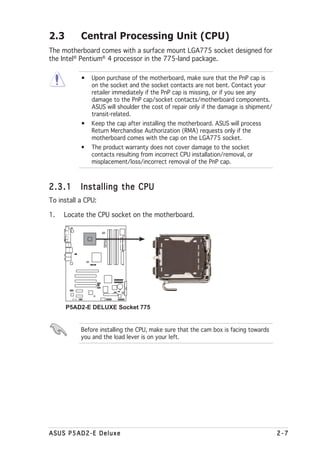
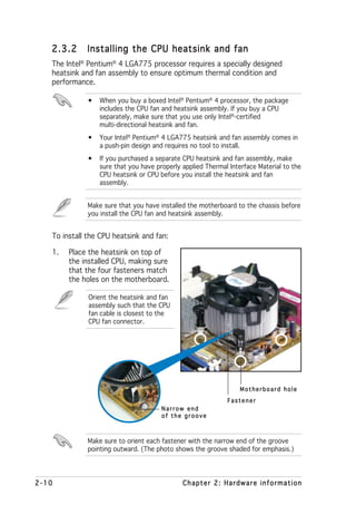
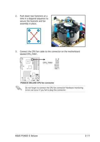
The document provides copyright information and safety notices for a motherboard manual. It lists the motherboard model as P5AD2-E Deluxe and includes revision information. The document contains chapters that provide information about the motherboard's features, hardware installation, BIOS setup, software support, and CPU features.

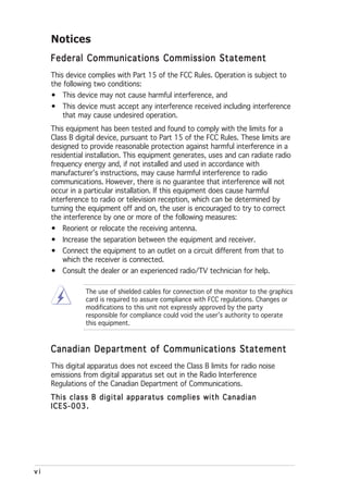

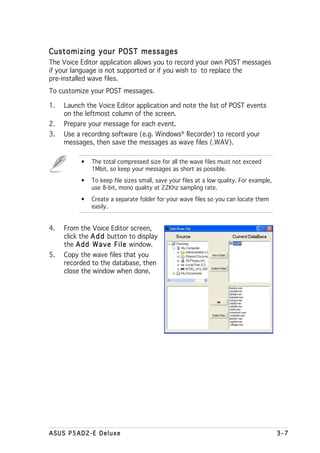
![Conventions used in this guide
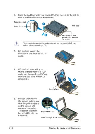
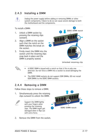
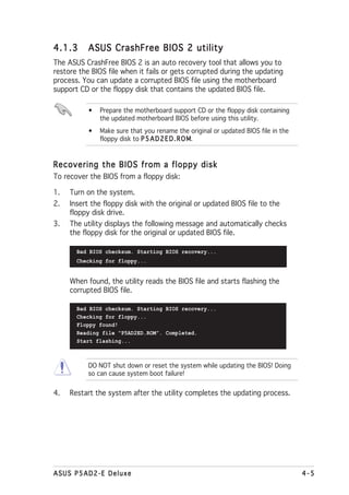
To make sure that you perform certain tasks properly, take note of the
following symbols used throughout this manual.
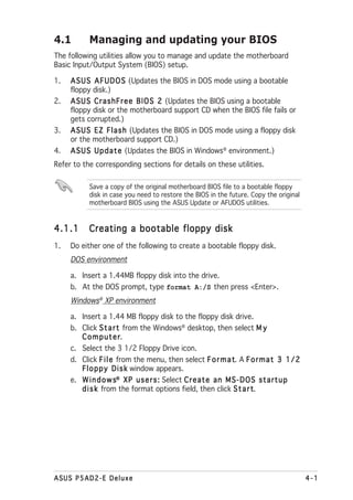
D A N G E R / W A R N I N G : Information to prevent injury to yourself
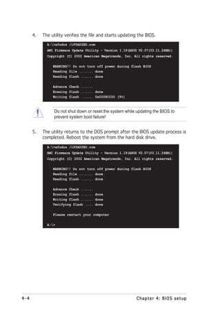
when trying to complete a task.
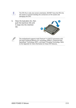
C A U T I O N : Information to prevent damage to the components
when trying to complete a task.
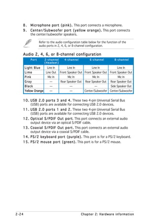
I M P O R T A N T : Instructions that you MUST follow to complete a
task.
N O T E : Tips and additional information to help you complete a
task.
Typography
Bold text Indicates a menu or an item to select.
Italics Used to emphasize a word or a phrase.
<Key> Keys enclosed in the less-than and greater-than sign means
that you must press the enclosed key.
Example: <Enter> means that you must press the Enter or
Return key.
<Key1+Key2+Key3> If you must press two or more keys simultaneously, the
key names are linked with a plus sign (+).
Example: <Ctrl+Alt+D>
Command Means that you must type the command exactly as shown,
then supply the required item or value enclosed in
brackets.
Example: At the DOS prompt, type the command line:
afudos /i[filename]
afudos /iP5GD2.ROM
ix](https://image.slidesharecdn.com/e1968p5ad2-edeluxe-110605220147-phpapp01/85/E1968-p5ad2-e-deluxe-9-320.jpg)

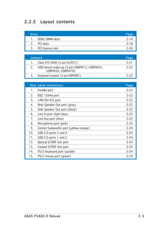
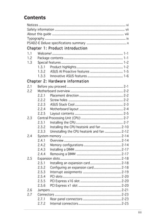
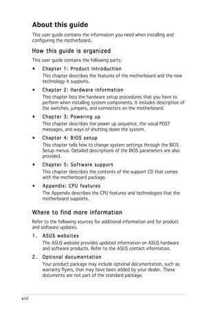
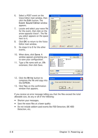
![Internal connectors Page
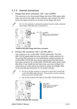
1. Floppy disk drive connector (34-1 pin FLOPPY) 2-25
2. Primary IDE connector (40-1 pin PRI_IDE1) 2-25
3. IDE RAID connectors (40-1 pin PRI_RAID1 [red], 2-26
SEC_RAID1 [red])
4. Serial ATA connectors (7-pin SATA1 [red], SATA2 [red], 2-26
SATA3 [black], SATA4 [black)
5. Optical drive audio connector (4-pin CD) 2-28
6. Front panel audio connector (10-1 pin AAFP) 2-28
7. USB connectors (10-1 pin USB56, USB78) 2-29
8. IEEE 1394a port connector (10-1 pin IE1394_2) 2-29
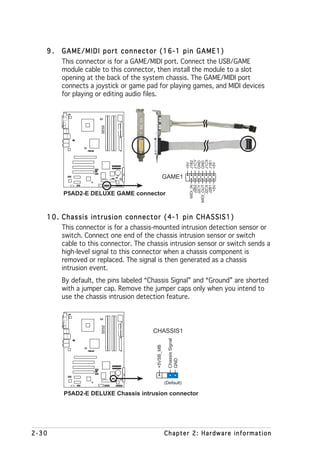
9. GAME/MIDI port connector (16-1 pin GAME1) 2-30
10. Chassis intrusion connector (4-1 pin CHASSIS1) 2-30
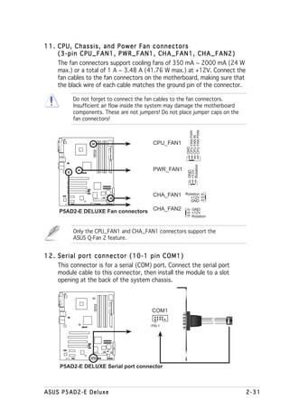
11. CPU, Chassis, and Power Fan connectors (3-pin CPU_FAN1,
PWR_FAN1, CHA_FAN1, CHA_FAN2) 2-31
12. Serial port connector (10-1 pin COM1) 2-31
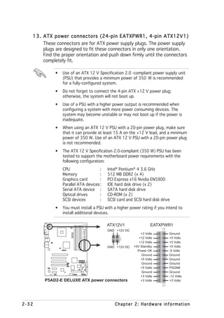
13. ATX power connectors (24-pin EATXPWR1, 4-pin ATX12V1) 2-32
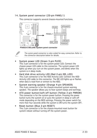
14. System panel connector (20-pin PANEL1) 2-33
System power LED (Green 3-pin PLED)
Hard disk drive activity LED (Red 2-pin IDE_LED)
System warnsing speaker (Orange 4-pin SPEAKER)
ATX power button/soft-off button (Yellow 2-pin PWRSW)
Reset button (Blue 2-pin RESET)
2-6 Chapter 2: Hardware information](https://image.slidesharecdn.com/e1968p5ad2-edeluxe-110605220147-phpapp01/85/E1968-p5ad2-e-deluxe-28-320.jpg)
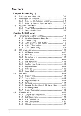
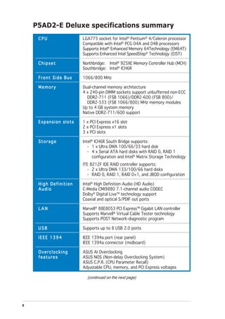
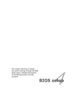
![3. IDE RAID connectors (40-1 pin PRI_RAID1 [red],
SEC_RAID1 [red])
These connectors are for Ultra ATA 133/100/66 signal cables. The
IDE RAID connectors support up to four IDE hard disk drives that you
can configure as a disk array through the onboard IDE RAID controller.
Refer to Chapter 5 for details on how to set up RAID configurations.
These connectors are set to I D E M o d e by default. In I D E M o d e you e,
can connect IDE devices to these connectors such as boot/data hard disk
drives or optical drives. If you intend to create an IDE RAID set using these
connectors, set the I T E 8 2 1 2 F C o n t r o l l e r item in the BIOS to [RAID
Mode]. See section “4.4.6 Onboard Devices Configuration” for details.
P5AD2-E
DELUXE
SEC_RAID1
NOTE: Orient the red markings
®
(usually zigzag) on the IDE
cable to PIN 1.
PRI_RAID1
PIN 1
P5AD2-E DELUXE RAID connectors
• Before creating a RAID set using Ultra ATA hard disks, make sure
that you have connected the Ultra ATA signal cable and installed Ultra
ATA 133/100/66 hard disk drives.
• The system automatically assigns the boot sequence of ATAPI
devices connected to the IDE RAID connectors.
• The ITE® 8212F controller supports a maximum of two Ultra ATA
hard disk drives in RAID 1 configuration.
• Before creating a RAID 1 set, make sure that you set the hard disk
drives as either Master or Slave device. Refer to the hard disk drive
documentation for details.
4. Serial ATA connectors (7-pin SATA1 [red], SATA2 [red],
SATA3 [black], SATA4 [black])
These connectors are for the Serial ATA signal cables for Serial ATA
hard disk drives.
If you installed Serial ATA hard disk drives, you can create a RAID 0 or
RAID 1 configuration with the Intel® Matrix Storage Technology
through the onboard Intel® ICH6R RAID controller. Refer to Chapter 5
for details on how to set up Serial ATA RAID configurations.
2-26 Chapter 2: Hardware information](https://image.slidesharecdn.com/e1968p5ad2-edeluxe-110605220147-phpapp01/85/E1968-p5ad2-e-deluxe-48-320.jpg)
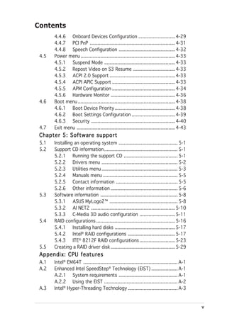
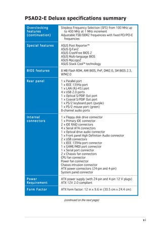
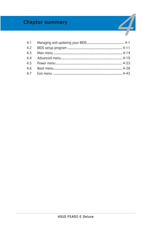
![These connectors are set to S t a n d a r d I D E mode by default. In
S t a n d a r d I D E mode, you can connect Serial ATA boot/data hard disk
drives to these connectors. If you intend to create a Serial ATA RAID set
using these connectors, set the C o n f i g u r e S A T A A s item in the BIOS
to [RAID]. See section “4.3.6 IDE Configuration” on page 4-16 for details.
P5AD2-E
DELUXE
SATA3 SATA4
RSATA_TXP4
RSATA_TXN4
RSATA_RXP4
RSATA_RXN4
RSATA_TXP3
RSATA_TXN3
RSATA_RXP3
RSATA_RXN3
GND
GND
GND
GND
GND
GND
®
SATA1 SATA2
RSATA_TXP2
RSATA_TXN2
RSATA_RXP2
RSATA_RXN2
GND
RSATA_TXP1
RSATA_TXN1
GND
RSATA_RXP1
RSATA_RXN1
GND
GND
GND
GND
P5AD2-E DELUXE SATA connectors
Important notes on Serial ATA
• You must install Windows® 2000 Service Pack 4 or the Windows® XP
Service Pack 1 before using Serial ATA hard disk drives. The Serial
ATA RAID feature (RAID 0/RAID 1) is available only if you are using
Windows® 2000/XP.
• Use only two Serial ATA RAID connectors for each RAID 0 or RAID 1
set.
• When using the connectors in S t a n d a r d I D E mode, connect the
primary (boot) hard disk drive to the SATA1 or SATA2 connector.
Refer to the table on the next page for the recommended SATA hard
disk drive connections.
• If your chassis supports only six hard disk drives or less, you can use
the Serial ATA extension module to install two additional external
SATA hard disk drives. The Serial ATA extension module is
purchased separately.
Serial ATA hard disk drive connection
Connector Color Setting Use
SATA1/SATA2 Red Master Boot disk
SATA3/SATA4 Black Slave Data disk
ASUS P5AD2-E Deluxe 2-27](https://image.slidesharecdn.com/e1968p5ad2-edeluxe-110605220147-phpapp01/85/E1968-p5ad2-e-deluxe-49-320.jpg)
![5. Optical drive audio connector (4-pin CD)
This connector is for the 4-pin audio cable that connects to the audio
connector at the back of the optical drive.
Right Audio Channel
Left Audio Channel
P5AD2-E
DELUXE
Ground
Ground
®
CD
P5AD2-E DELUXE CD audio connector
Enable the CD-IN function in the audio utility when using this
connector.
6. Front panel audio connector (10-1 pin AAFP)
This connector is for a chassis-mounted front panel audio I/O module
that supports either HD Audio or legacy AC’97 audio standard.
HD Audio front panel
audio pin definition
SENSE1_RETUR
SENSE2_RETUR
P5AD2-E
DELUXE
PRESENCE#
AGND
GND
NC
NC
NC
AAFP
®
MIC2
MICPWR
Line out_R
NC
Line out_L
PORT1 L
PORT1 R
PORT2 R
SENSE_SEND
PORT2 L
AC ‘97 audio
pin definition
P5AD2-E DELUXE Analog front panel connector
• It is recommended that you connect a high-definition front panel
audio module to this connector to avail the motherboard
high-definition audio capability.
• By default, this connector is set to legacy AC’97 audio. If you want
to connect a high-definition front panel audio module to this
connector, set the F r o n t P a n e l S u p p o r t T y p e item in the BIOS
Setup to [HD Audio]. See page 4-28 for details.
2-28 Chapter 2: Hardware information](https://image.slidesharecdn.com/e1968p5ad2-edeluxe-110605220147-phpapp01/85/E1968-p5ad2-e-deluxe-50-320.jpg)
![7. USB connectors (10-1 pin USB56, USB78)
These connectors are for USB 2.0 ports. Connect the USB/GAME
module cable to any of these connectors, then install the module to a
slot opening at the back of the system chassis. These USB connectors
comply with USB 2.0 specification that supports up to 480 Mbps
connection speed.
P5AD2-E
DELUXE
®
USB_P6+
USB_P8+
USB_P6-
USB_P8-
USB+5V
USB+5V
GND
GND
NC
NC
USB56 USB78
1 1
USB+5V
USB_P5-
USB_P5+
GND
USB+5V
USB_P7-
USB_P7+
GND
P5AD2-E DELUXE USB 2.0 connectors
Never connect a 1 3 9 4 c a b l e to the USB connectors. Doing so will
damage the motherboard!
8. 4a
I E E E 1 3 9 4a port connector (10-1 pin IE1394_2 [orange])
This connector is for an additional IEEE 1394 port. Connect the IEEE
1394 module cable (orange) to this connector, then install the
module to a slot opening at the back of the system chassis.
P5AD2-E
DELUXE
®
TPB2-
TPA2-
+12V
GND
GND
IE1394_2
1
TPA2+
GND
TPB2+
+12V
P5AD2-E DELUXE IEEE 1394 connector
Never connect a U S B p o r t m o d u l e c a b l e to the IEEE 1394
connector. Doing so will damage the motherboard!
ASUS P5AD2-E Deluxe 2-29](https://image.slidesharecdn.com/e1968p5ad2-edeluxe-110605220147-phpapp01/85/E1968-p5ad2-e-deluxe-51-320.jpg)


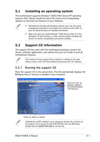
![Windows® 2000 environment
To create a set of boot disks for Windows® 2000:
a. Insert a formatted, high density 1.44 MB floppy disk into the drive.
b. Insert the Windows® 2000 CD to the optical drive.
c. Click S t a r t then select R u n
t, n.
d. In the O p e n field, type D:bootdiskmakeboot a:
assuming that D is your optical drive letter.
e. Press <Enter>, then follow screen instructions to continue.
2. Copy the original or the latest motherboard BIOS file to the bootable
floppy disk.
4.1.2 AFUDOS utility
The AFUDOS utility allows you to update the BIOS file in DOS environment
using a bootable floppy disk with the updated BIOS file. This utility also
allows you to copy the current BIOS file that you can use as backup when
the BIOS fails or gets corrupted during the updating process.
Copying the current BIOS
To copy the current BIOS file using the AFUDOS utility:
• Make sure that the floppy disk is not write-protected and has at
least 1.2 MB free space to save the file.
• The succeeding BIOS screens are for reference only. The actual BIOS
screen displays may not be same as shown.
1. Copy the AFUDOS utility (afudos.exe) from the motherboard support
CD to the bootable floppy disk you created earlier.
2. Boot the system in DOS mode, then at the prompt type:
afudos /o[filename]
where the [filename] is any user-assigned filename not more than
eight alphanumeric characters for the main filename and three
alphanumeric characters for the extension name.
A:>afudos /oOLDBIOS1.rom
Main filename Extension name
4-2 Chapter 4: BIOS setup](https://image.slidesharecdn.com/e1968p5ad2-edeluxe-110605220147-phpapp01/85/E1968-p5ad2-e-deluxe-70-320.jpg)
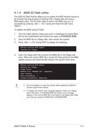
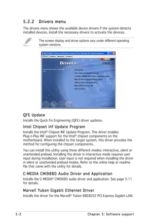
![3. Press <Enter>. The utility copies the current BIOS file to the floppy
disk.
A:>afudos /oOLDBIOS1.rom
AMI Firmware Update Utility - Version 1.19(ASUS V2.07(03.11.24BB))
Copyright (C) 2002 American Megatrends, Inc. All rights reserved.
Reading flash ..... done
Write to file...... ok
A:>
The utility returns to the DOS prompt after copying the current BIOS
file.
Updating the BIOS file
To update the BIOS file using the AFUDOS utility:
1. Visit the ASUS website (www.asus.com) and download the latest BIOS
file for the motherboard. Save the BIOS file to a bootable floppy disk.
Write the BIOS filename on a piece of paper. You need to type the exact
BIOS filename at the DOS prompt.
2. Copy the AFUDOS utility (afudos.exe) from the motherboard support
CD to the bootable floppy disk you created earlier.
3. Boot the system in DOS mode, then at the prompt type:
afudos /i[filename]
where [filename] is the latest or the original BIOS file on the bootable
floppy disk.
A:>afudos /iP5AD2ED.rom
ASUS P5AD2-E Deluxe 4-3](https://image.slidesharecdn.com/e1968p5ad2-edeluxe-110605220147-phpapp01/85/E1968-p5ad2-e-deluxe-71-320.jpg)
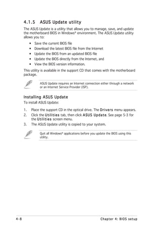
![4.2.1 BIOS menu screen
Menu items Menu bar Configuration fields General help
System Time [11:51:19] Use [ENTER], [TAB]
System Date [Thu 05/07/2004] or [SHIFT-TAB] to
Legacy Diskette A [1.44M, 3.5 in] select a field.
Language [English]
Use [+] or [-] to
Primary IDE Master : [ST320413A] configure system time.
Primary IDE Slave : [ASUS CD-S520/A]
Third IDE Master : [Not Detected]
Third IDE Slave : [Not Detected]
Fourth IDE Master : [Not Detected]
Fourth IDE Slave : [Not Detected]
IDE Configuration Select Screen
Select Item
+- Change Field
System Information Tab Select Field
F1 General Help
F10 Save and Exit
ESC Exit
Sub-menu items Navigation keys
4.2.2 Menu bar
The menu bar on top of the screen has the following main items:
Main For changing the basic system configuration
Advanced For changing the advanced system settings
Power For changing the advanced power management (APM)
configuration
Boot For changing the system boot configuration
Exit For selecting the exit options and loading default
settings
To select an item on the menu bar, press the right or left arrow key on the
keyboard until the desired item is highlighted.
4.2.3 Navigation keys
At the bottom right corner of a menu screen are the navigation keys for
that particular menu. Use the navigation keys to select items in the menu
and change the settings.
Some of the navigation keys differ from one screen to another.
4-12 Chapter 4: BIOS setup](https://image.slidesharecdn.com/e1968p5ad2-edeluxe-110605220147-phpapp01/85/E1968-p5ad2-e-deluxe-80-320.jpg)
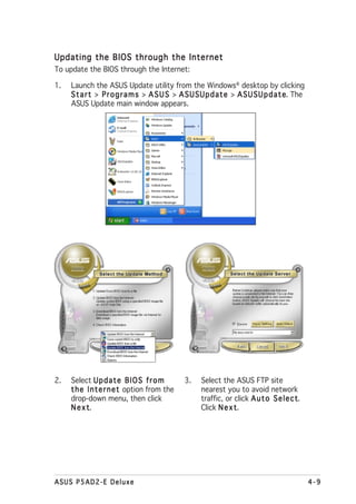
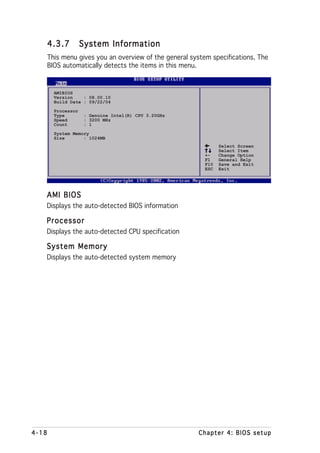
![4.2.4 Menu items
The highlighted item on the menu bar
System Time [11:10:19] Use [ENTER], [TAB]
displays the specific items for that System Date
Legacy Diskette A
Language
[Thu 03/27/2003]
[1.44M, 3.5 in]
[English]
or [SHIFT-TAB] to
select a field.
Use [+] or [-] to
menu. For example, selecting M a i n Primary IDE Master
Primary IDE Slave
Secondary IDE Master
:[ST320413A]
:[ASUS CD-S340]
:[Not Detected]
configure system time.
Secondary IDE Slave :[Not Detected]
shows the Main menu items. Third IDE Master
Fourth IDE Master
IDE Configuration
:[Not Detected]
:[Not Detected]
Select Screen
Select Item
System Information +- Change Field
Tab Select Field
The other items (Advanced, Power,
F1 General Help
F10 Save and Exit
ESC Exit
Boot, and Exit) on the menu bar have
their respective menu items.
Main menu items
4.2.5 Sub-menu items
A solid triangle before each item on any menu screen means that the iteam
has a sub-menu. To display the sub-menu, select the item and press
<Enter>.
4.2.6 Configuration fields
These fields show the values for the menu items. If an item is user-
configurable, you can change the value of the field opposite the item. You
cannot select an item that is not user-configurable.
A configurable field is enclosed in brackets, and is highlighted when
selected. To change the value of a field, select it then press <Enter> to
display a list of options. Refer to “4.2.7 Pop-up window.”
4.2.7 Pop-up window
Select a menu item then press <Enter> to display a pop-up window with
the configuration options for that item.
4.2.8 Scroll bar
Advanced Chipset settings
A scroll bar appears on the right side WARNING: Setting wrong values in the sections below
may cause system to malfunction.
of a menu screen when there are items
Configure DRAM Timing by SPD [Enabled]
Memory Acceleration Mode [Auto]
DRAM Idle Timer [Auto]
DRAm Refresh Rate [Auto]
that do not fit on the screen. Press the Graphic Adapter Priority
Graphics Aperture Size
Spread Spectrum
[AGP/PCI]
[ 64 MB]
[Enabled] Select Screen
Up/Down arrow keys or <Page Up> /
Select Item
ICH Delayed Transaction [Enabled] +- Change Option
F1 General Help
MPS Revision [1.4] F10 Save and Exit
<Page Down> keys to display the other
ESC Exit
items on the screen.
Pop-up window
4.2.9 General help
Scroll bar
At the top right corner of the menu
screen is a brief description of the
selected item.
ASUS P5AD2-E Deluxe 4-13](https://image.slidesharecdn.com/e1968p5ad2-edeluxe-110605220147-phpapp01/85/E1968-p5ad2-e-deluxe-81-320.jpg)
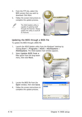
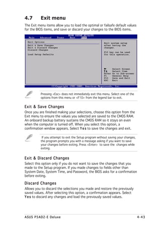
![4.3 Main menu
When you enter the BIOS Setup program, the M a i n menu screen appears,
giving you an overview of the basic system information.
Refer to section “4.2.1 BIOS menu screen” for information on the menu
screen items and how to navigate through them.
System Time [11:51:19] Use [ENTER], [TAB]
System Date [Thu 05/07/2004] or [SHIFT-TAB] to
Legacy Diskette A [1.44M, 3.5 in] select a field.
Language [English]
Use [+] or [-] to
Primary IDE Master : [ST320413A] configure system time.
Primary IDE Slave : [ASUS CD-S520/A]
Third IDE Master : [Not Detected]
Third IDE Slave : [Not Detected]
Fourth IDE Master : [Not Detected]
Fourth IDE Slave : [Not Detected]
IDE Configuration Select Screen
Select Item
+- Change Field
System Information Tab Select Field
F1 General Help
F10 Save and Exit
ESC Exit
4.3.1 System Time [xx:xx:xxxx]
Allows you to set the system time.
4.3.2 System Date [Day xx/xx/xxxx]
Allows you to set the system date.
4.3.3 Legacy Diskette A [1.44M, 3.5 in.]
Sets the type of floppy drive installed. Configuration options: [Disabled]
[360K, 5.25 in.] [1.2M , 5.25 in.] [720K , 3.5 in.] [1.44M, 3.5 in.]
[2.88M, 3.5 in.]
4.3.4 Language [English]
Allows you to choose the BIOS language version from the options.
Configuration options: [English] [Français] [Deutsch] [Japanese]
[Chinese (GB)] [Chinese BIG5]
4-14 Chapter 4: BIOS setup](https://image.slidesharecdn.com/e1968p5ad2-edeluxe-110605220147-phpapp01/85/E1968-p5ad2-e-deluxe-82-320.jpg)
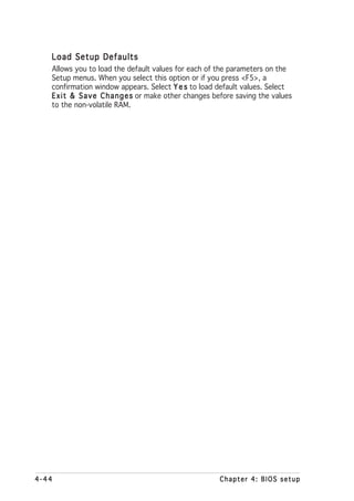
![4.3.5 Primary, Third and Fourth IDE Master/Slave
The BIOS automatically detects the connected IDE devices. There is a
separate sub-menu for each IDE device. Select a device item, then press
<Enter> to display the IDE device information.
Primary IDE Master
Select the type
Device : Hard Disk of device connected
Vendor : ST320413A to the system.
Size : 20.0GB
LBA Mode : Supported
Block Mode : 16 Sectors
PIO Mode : Supported
Async DMA : MultiWord DMA-2
Ultra DMA : Ultra DMA-5
SMART Monitoring: Supported
Type [Auto] Select Screen
LBA/Large Mode [Auto] Select Item
Block(Multi-sector Transfer) [Auto] +- Change Option
PIO Mode [Auto] F1 General Help
DMA Mode [Auto] F10 Save and Exit
SMART Monitoring [Auto] ESC Exit
32Bit Data Transfer [Disabled]
The BIOS automatically detects the values opposite the dimmed items
(Device, Vendor, Size, LBA Mode, Block Mode, PIO Mode, Async DMA, Ultra
DMA, and SMART monitoring). These values are not user-configurable.
These items show N/A if no IDE device is installed in the system.
Type [Auto]
Selects the type of IDE drive. Setting to [Auto] allows automatic selection
of the appropriate IDE device type. Select [CDROM] if you are specifically
configuring a CD-ROM drive. Select [ARMD] (ATAPI Removable Media
Device) if your device is either a ZIP, LS-120, or MO drive.
Configuration options: [Not Installed] [Auto] [CDROM] [ARMD]
LBA/Large Mode [Auto]
Enables or disables the LBA mode. Setting to [Auto] enables the LBA mode
if the device supports this mode, and if the device was not previously
formatted with LBA mode disabled. Configuration options: [Disabled]
[Auto]
Block (Multi-sector Transfer) [Auto]
Enables or disables data multi-sectors transfers. When set to [Auto], the
data transfer from and to the device occurs multiple sectors at a time if
the device supports multi-sector transfer feature. When set to [Disabled],
the data transfer from and to the device occurs one sector at a time.
Configuration options: [Disabled] [Auto]
ASUS P5AD2-E Deluxe 4-15](https://image.slidesharecdn.com/e1968p5ad2-edeluxe-110605220147-phpapp01/85/E1968-p5ad2-e-deluxe-83-320.jpg)
![PIO Mode [Auto]
Selects the PIO mode.
Configuration options: [Auto] [0] [1] [2] [3] [4]
SMART Monitoring [Auto]
Sets the Smart Monitoring, Analysis, and Reporting Technology.
Configuration options: [Auto] [Disabled] [Enabled]
32Bit Data Transfer [Disabled]
Enables or disables 32-bit data transfer.
Configuration options: [Disabled] [Enabled]
4.3.6 IDE Configuration
The items in this menu allow you to set or change the configurations for
the IDE devices installed in the system. Select an item then press <Enter>
if you want to configure the item.
IDE Configuration When in AHCI/RAID
Configure SATA As [Standard IDE] mode SATA
Onboard IDE Operate Mode [Enhanced Mode] controller is
Enhanced Mode Support On [S-ATA] forced to Native
mode.
IDE Detect Time Out (Sec) [35]
Configure SATA As [Standard IDE]
Sets the configuration for the Serial ATA connectors supported by the
Southbridge chip.
The AHCI allows the onboard storage driver to enable advanced Serial ATA
features that increases storage performance on random workloads by
allowing the drive to internally optimize the order of commands.
If you want to create a RAID 0, RAID 1, or the Intel® Matrix Storage
Technology configuration from the Serial ATA hard disk drives, set this
item to [RAID].
If you want to use the Serial ATA hard disk drives as Parallel ATA physical
storage devices, set this item to [Standard IDE].
If you want the Serial ATA hard disk drives to use the Advanced Host
Controller Interface (AHCI), set this item to [AHCI]. For details on AHCI, go to:
www.intel.com/support/chipsets/imst/sb/CS-012304.htm
www.intel.com/support/chipsets/imst/sb/CS-012305.htm
The SATA controller is set to Native mode when this item is set to [RAID]
or [AHCI]
4-16 Chapter 4: BIOS setup](https://image.slidesharecdn.com/e1968p5ad2-edeluxe-110605220147-phpapp01/85/E1968-p5ad2-e-deluxe-84-320.jpg)
![Onboard IDE Operate Mode [Enhanced Mode]
Allows selection of the IDE operation mode depending on the installed
operating system (OS). Set to [Enhanced Mode] if you are using native OS
including Windows® 2000/XP. Configuration options: [Disabled]
[Compatible Mode] [Enhanced Mode]
Enhanced Mode Support On [S-ATA]
Allows you to use native OS on Serial ATA and Parallel ATA ports. It is
recommend that you do not change the default setting for better OS
compatibility. In this setting, you may use legacy OS on the Parallel
ATA ports only if you do not install any Serial ATA device.
The P-ATA+S-ATA and P-ATA options are for advanced users only. If
you set to any of these options and encountered problems, revert to
the default setting S - A T A Configuration options: [P-ATA+S-ATA]
A.
[S-ATA] [P-ATA]
The O n b o a r d I D E O p e r a t e M o d e and its sub-menu items appear
only when the C o n f i g u r e S A T A A s item is set to [Standard IDE].
Onboard Serial-ATA BOOTROOM [Disabled]
Enables or disables the onboard Serial ATA boot ROM. This item
appears only when the Configure SATA As item is set as RAID.
Configuration options: [Disabled] [Enabled]
The O n b o a r d S e r i a l - A T A B O O T R O M appears only when the
C o n f i g u r e S A T A A s item is set to [RAID].
ALPE and ASP [Disabled]
Allows you to enable or disable the Agressive Link Power Management
(ALPE) and Aggressive Slumber/Partial (ASP) management features.
Configuration options: [Disabled] [Enabled]
AHCI Port 3 Interlock Switch [Disabled]
Enables or disables the Advanced Host Controller Interface (AHCI) Port
3 interlock switch. Configuration options: [Disabled] [Enabled]
The A L P E a n d A S P and its sub-menu item appear only when the
C o n f i g u r e S A T A A s item is set to [AHCI].
IDE Detect Time Out [35]
Selects the time out value for detecting ATA/ATAPI devices.
Configuration options: [0] [5] [10] [15] [20] [25] [30] [35]
ASUS P5AD2-E Deluxe 4-17](https://image.slidesharecdn.com/e1968p5ad2-edeluxe-110605220147-phpapp01/85/E1968-p5ad2-e-deluxe-85-320.jpg)
![4.4 Advanced menu
The Advanced menu items allow you to change the settings for the CPU
and other system devices.
Take caution when changing the settings of the Advanced menu items.
Incorrect field values can cause the system to malfunction.
JumperFree Configuration Adjust system
LAN Cable Status frequency/voltage.
USB Configuration
CPU Configuration
Chipset
Onboard Devices Configuration
PCIPnP
Speech Configuration
4.4.1 JumperFree Configuration
Configure System Frequency/Voltage Select the targe CPU
AI Overclocking [Auto] frequency, and the
relevant parameters
Performance Mode [Auto] will be auto-adjusted.
Frequencies higher
than CPU manufacturer
AiBooster Support [Auto] recommends are not
CPU Lock Free [Auto] guaranteed to be
stable. If the system
becomes unstable,
return to the default.
AI Overclocking [Auto]
Allows you to select the overclocking options to achieve the desired CPU
internal frequency. Select either one of the preset overclocking
configiuration options.
M a n u a l - allows you to individually set overclocking parameters.
A u t o - loads the optimal settings for the system.
A I N O S - the ASUS AI Non-delay Overclocking System feature
intelligently determines the system load and automatically boost
the performance for the most demanding tasks.
S t a n d a r d - loads the standard settings for the system.
O v e r c l o c k P r o f i l e - loads overclocking profiles with optimal
parameters for stability when overclocking.
ASUS P5AD2-E Deluxe 4-19](https://image.slidesharecdn.com/e1968p5ad2-edeluxe-110605220147-phpapp01/85/E1968-p5ad2-e-deluxe-87-320.jpg)
![Performance Mode [Auto]
Allows enhanced system performance. setting to [Turbo] may cause the
system to become unstable. If this happens, revert to the default setting
[Auto]. Configuration options: [Auto] [Standard] [Turbo]
AiBooster Support [Enabled]
Enables or disables the system support for the Ai Booster overclocking
application. Refer to the Ai Booster help file for details.
The following item appears only when you install a CPU that supports the
lock free feature. Only some latest CPUs support this feature.
CPU Lock Free [Auto]
Allows you to adjust the CPU multiplier to 14x. Setting this item to [Auto]
allows the motherboard to automatically reduce the CPU multiplier value for
more flexibility when increasing the external FSB.
Configuration options: [Auto] [Disabled] [Enabled]
The following item appears only when you set the A I O v e r c l o c k i n g
item to [Manual].
CPU Frequency [XXX]
Displays the frequency sent by the clock generator to the system bus and
PCI bus. The value of this item is auto-detected by the BIOS. Use the < + >
and < - > keys to adjust the CPU frequency. You can also type the desired
CPU frequency using the numeric keypad. The values range from 100 to
400. Refer to the table below for the correct Front Side Bus and CPU
External Frequency settings.
FSB/CPU External Frequency Synchronization
Front Side Bus CPU External Frequency
FSB 1066 266 MHz
FSB 800 200 MHz
FSB 533 133 MHz
DRAM Frequency [Auto]
Allows you to set the DDR operating frequency.
Configuration options: [Auto] [400MHz] [533MHz] [600MHz] [711MHz]
Selecting a very high DRAM frequency may cause the system to become
unstable! If this happens, revert to the default setting.
Set the DRAM frequency to 600 MHz if your system is running at FSB
800. Set the item to 711 MHz if your system is running at FSB 1066.
4-20 Chapter 4: BIOS setup](https://image.slidesharecdn.com/e1968p5ad2-edeluxe-110605220147-phpapp01/85/E1968-p5ad2-e-deluxe-88-320.jpg)
![PCI Express Frequency [Auto]
Allows you to set the PCI Express frequency. This item is set to [Auto] by
default. Configuration options: [Auto] [90]...[150]
PCI Clock Synchronization Mode [Auto]
Allows you to synchronize the PCI frequency with the PCI Express or CPU
frequency. Configuration options: [To CPU] [33.33MHz] [Auto]
Spread Spectrum [Auto]
Allows you to enable or disable the clock generator spread spectrum.
Configuration options: [Disabled] [Enabled] [Auto]
The following items also appear when the A I O v e r c l o c k i n g item is set
to [AI NOS].
Memory Voltage [Auto]
Allows you to select the DDR2 reference voltage.
Configuration options: [Auto] [1.80V] [1.85V] [1.90V] [1.95V] [2.00V]
[2.05V] [2.10V] [2.20V] [Auto]
Refer to the DDR2 documentation before adjusting the memory voltage.
Setting a very high memory voltage may damage the memory module(s)!
Chipset Core Voltage [Auto]
Allows you to select the chipset core voltage.
Configuration options: [Auto] [1.50V] [1.55V] [1.60V] [1.65V] [1.70V]
[1.75V] [1.80V]
Setting a high chipset core voltage may damage the chipset!
CPU VCore Voltage [Auto]
Allows you to select the CPU VCore voltage. Configuration options: [Auto]
[1.8000V] [1.7875V] [1.7750V] [1.7625V] [1.7500V] [1.7375V]
[1.7250V] [1.7125V] [1.7000V] [1.6875V] [1.6750V] [1.6625V]
[1.6500V] [1.6375V] [1.6250V] [1.6125V] [1.6000V] [1.5875V]
[1.5750V] [1.5625V] [1.5500V] [1.5375V] [1.5250V] [1.5125V]
[1.5000V] [1.4875V] [1.4750V] [1.4625V] [1.4500V] [1.4375V]
[1.4250V] [1.4125V] [1.4000V] [1.3875V] [1.3750V] [1.3625V]
[1.3500V] [1.3375V] [1.3250V] [1.3125V] [1.3000V] [1.2875V]
Refer to the CPU documentation before setting the CPU Vcore voltage.
Setting a high Vcore voltage may damage the CPU!
ASUS P5AD2-E Deluxe 4-21](https://image.slidesharecdn.com/e1968p5ad2-edeluxe-110605220147-phpapp01/85/E1968-p5ad2-e-deluxe-89-320.jpg)
![FSB Termination Voltage [Auto]
Allows you to select the front side bus termination voltage.
Configuration options: [Auto] [1.20V] [1.25V] [1.30V] [1.40V]
The following item appears only when the A I O v e r c l o c k i n g item is set
to [Overclock Profile].
Overclock Options [Overclock 5%]
Allows you to overclock the CPU speed through the available preset values.
Configuration options: [Overclock 5%] [FSB888/DDR2-667]
[Overclock 10%] [FSB1000/DDR2-667]
[Overclock 15%] [FSB1200/DDR2-600]
[Overclock 20%] [FSB1200/DDR2-800]
[Overclock 30%] [FSB1333/DDR2-667]
The following item appears only when the A I O v e r c l o c k i n g item is set
to [AI NOS].
NOS Mode [Auto]
Sets the Non-Delay Overclocking System mode. Select either of the
following configuration options:
A u t o - loads the optimum sensitivity and overclocking percentage
setting.
S t a n d a r d - activates overclocking on a threshold between light and
heavy CPU loading.
S e n s i t i v e - activates overclocking on a light CPU loading.
H e a v y L o a d - activates overclocking on a heavy CPU loading.
The following items appear only when the N O S M o d e item is set to
[Standard], [Sensitive], or [Heavy].
Turbo NOS [Overclock XX%]
Allows you to set the overclock percentage for the selected NOS Mode.
Configuration options: [Overclock 3%] [Overclock 5%] [Overclock 7%]
[Overclock 10%] [Overclock 15%] [Overclock 20%] [Disabled]
Twin Turbo NOS [Disabled]
Allows you to disable or set the overclock percentage for the selected
Turbo NOS. Configuration options: [Disabled] [Overclock 5%]
[Overclock 7%] [Overclock 10%] [Overclock 15%] [Overclock 20%]
[Overclock 30%]
4-22 Chapter 4: BIOS setup](https://image.slidesharecdn.com/e1968p5ad2-edeluxe-110605220147-phpapp01/85/E1968-p5ad2-e-deluxe-90-320.jpg)
![4.4.2 LAN Cable Status
This menu displays the status of the Local Area Network (LAN) cable
connected to the LAN (RJ-45) port.
POST Check LAN Cable [Disabled] Check LAN cable
during POST.
LAN Cable Status
Pair Status Length
1-2 Normal N/A
3-6 Normal N/A
4-5 Normal N/A
7-8 Normal N/A
1-2 Normal N/A
3-6 Normal N/A
4-5 Normal N/A
7-8 Normal N/A
POST Check LAN Cable [Disabled]
Allows you to enable or disable LAN cable check during POST. When
enabled, the menu reports the cable faults or shorts, and displays the point
(length) where the fault or short is detected.
Configuration options: [Disabled] [Enabled]
ASUS P5AD2-E Deluxe 4-23](https://image.slidesharecdn.com/e1968p5ad2-edeluxe-110605220147-phpapp01/85/E1968-p5ad2-e-deluxe-91-320.jpg)
![4.4.3 USB Configuration
The items in this menu allows you to change the USB-related features.
Select an item then press <Enter> to display the configuration options.
USB Configuration Enables USB host
Module Version - 2.23.2-9.4 controllers.
USB Devices Enabled: None
USB Function [8 USB Ports]
Legacy USB Support [Auto]
USB 2.0 Controller [Disabled]
USB 2.0 Controller Mode [HiSpeed]
BIOS EHCI Hand-Off [Enabled]
The M o d u l e V e r s i o n and U S B D e v i c e s E n a b l e d items show the
auto-detected values. If no USB device is detected, the item shows
None e.
USB Function [X USB Ports]
Allows the BIOS to auto-detect the number of USB ports in your system.
Setting this item to [Disable] disables the USB function.
Configuration options: [Disabled] [2 USB Ports] [4 USB Ports]
[6 USB Ports] [8 USB Ports]
Legacy USB Support [Auto]
Allows you to enable or disable support for legacy USB devices. Setting to
[Auto] allows the system to detect the presence of USB devices at
startup. If detected, the USB controller legacy mode is enabled. If no USB
device is detected, the legacy USB support is disabled.
Configuration options: [Disabled] [Enabled] [Auto]
USB 2.0 Controller [Disabled]
Allows you to enable or disable the USB 2.0 controller.
Configuration options: [Enabled] [Disabled]
USB 2.0 Controller Mode [HiSpeed]
Allows you to set the USB 2.0 controller mode to HiSpeed (480 Mbps) or
FullSpeed (12 Mbps). Configuration options: [FullSpeed] [HiSpeed]
BIOS EHCI Hand-Off [Enabled]
Allows you to enable support for operating systems without an EHCI
hand-off feature. Configuration options: [Enabled] [Disabled]
4-24 Chapter 4: BIOS setup](https://image.slidesharecdn.com/e1968p5ad2-edeluxe-110605220147-phpapp01/85/E1968-p5ad2-e-deluxe-92-320.jpg)
![4.4.4 CPU Configuration
The items in this menu show the CPU-related information that the BIOS
automatically detects.
Configure Advanced CPU settings Sets the ratio
Manufacturer: Intel between CPU Core
Brand String: Genuine Intel(R) CPU 3.20GHz Clock and the FSB
Frequency : 3200 MHz Frequency.
FSB Speed : 800 MHz NOTE: If an invalid
ratio is set in CMOS
Cache L1 : 16 KB then actual and
Cache L2 : 1024 KB setpoint values may
Cache L3 : 0 KB differ.
Ratio Status: Unlocked
Ratio Actual Value : 16
Ratio CMOS Setting: [ 18] Select Screen
VID CMOS Setting: [ 62] Select Item
CPU Lock Free [Auto] +- Change Option
Microcode Updation [Enabled] F1 General Help
Max CPUID Value Limit: [Disabled] F10 Save and Exit
Enhanced C1 Control [Auto] ESC Exit
CPU Internal Thermal Control [Auto]
Ratio CMOS Setting [ 8]
Sets the ratio between the CPU core clock and the Front Side Bus
frequency. The BIOS auto-detects the default value of this item. Use the
< + > or < - > keys to adjust the values. Configuration options: [ 8]...[28]
You can only adjust the R a t i o C M O S if you installed an unlocked CPU.
Refer to the CPU documentation for details.
VID CMOS Setting [ 45]
Allows you to set the VID CMOS setting at which the processor is to run.
The BIOS auto-detects the default value of this item. Use the < + > or < - >
keys to adjust the values.
The following item appears only when you install a CPU that supports the
lock free feature. Only some latest CPUs support this feature.
CPU Lock Free [Auto]
Allows you to adjust the CPU multiplier to 14x. Setting this item to [Auto]
allows the motherboard to automatically reduce the CPU multiplier value for
more flexibility when increasing the external FSB.
Configuration options: [Auto] [Disabled] [Enabled]
Microcode Updation [Enabled]
Allows you to enable or disable the microcode updation.
Configuration options: [Disabled] [Enabled]
ASUS P5AD2-E Deluxe 4-25](https://image.slidesharecdn.com/e1968p5ad2-edeluxe-110605220147-phpapp01/85/E1968-p5ad2-e-deluxe-93-320.jpg)
![Max CPUID Value Limit [Disabled]
Setting this item to [Enabled] allows legacy operating systems to boot
even without support for CPUs with extended CPUID functions.
Configuration options: [Disabled] [Enabled]
Enhanced C1 Control [Auto]
When set to [Auto], the BIOS automatically checks the CPU’s capability to
enable the C1E support. In C1E mode, the CPU power consumption is lower
when idle. Configuration options: [Auto] [Disabled]
CPU Internal Thermal Control [Auto]
Allows you to disable or set to auto the CPU Internal Thermal Control
function. Configuration options: [Auto] [Disabled]
Scroll down the screen to display the following items.
Hyper-Threading Technology [Enabled]
Allows you to enable or disable the processor Hyper-Threading Technology.
Refer to the Appendix for more information on the Hyper-Threading
Technology. Configuration options: [Disabled] [Enabled]
The following item appears only when you installed an Intel® Pentium® 4
CPU that supports the Enhanced Intel SpeedStep® Technology (EIST).
Intel(R) SpeedStep Technology [Automatic]
Allows you to use the Enhanced Intel SpeedStep® Technology. When set to
[Automatic], you can adjust the system power settings in the operating
system to use the EIST feature.
Set this item to [Maximum] or [Disabled] if you do not want to use the EIST.
The CPU constantly operates at a lower internal frequency when you set
this item to [Minimum].
Configuration options: [Maximum] [Minimum] [Automatic] [Disabled]
• Refer to the Appendix for details on how to use the EIST feature.
• The motherboard comes with a BIOS file that supports EIST.
4-26 Chapter 4: BIOS setup](https://image.slidesharecdn.com/e1968p5ad2-edeluxe-110605220147-phpapp01/85/E1968-p5ad2-e-deluxe-94-320.jpg)
![4.4.5 Chipset
The Chipset menu allows you to change the advanced chipset settings.
Select an item then press <Enter> to display the sub-menu.
Advanced Chipset Settings Enable or disable
Configure DRAM Timing by SPD [Enabled] DRAM timing.
Hyper Path 2 [Auto]
Booting Graphic Adapter Priori [PCI Express/PCI]
PEG Buffer Length [Auto]
Link Latency [Auto]
PEG Link Mode [Auto]
PEG Root Control [Auto]
Slot Power [Auto]
Advanced Chipset Settings
Configure DRAM Timing by SPD [Enabled]
When this item is enabled, the DRAM timing parameters are set according
to the DRAM SPD (Serial Presence Detect). When disabled, you can
manually set the DRAM timing parameters through the DRAM sub-items.
The following sub-items appear when this item is Disabled.
Configuration options: [Disabled] [Enabled]
DRAM CAS# Latency [5 Clocks]
Controls the latency between the SDRAM read command and the time
the data actually becomes available.
Configuration options: [5 Clocks] [4 Clocks] [3 Clocks]
DRAM RAS# Precharge [4 Clocks]
Controls the idle clocks after issuing a precharge command to the DDR
SDRAM. Configuration options: [2 Clocks] [3 Clocks] [4 Clocks] [5 Clocks]
DRAM RAS# to CAS# Delay [4 Clocks]
Controls the latency between the DDR SDRAM active command and
the read/write command. Configuration options: [2 Clocks] [3 Clocks]
[4 Clocks] [5 Clocks]
DRAM RAS# Activate to Precharge Delay [15 Clocks]
Configuration options: [1 Clock]...[15 Clocks]
DRAM Write Recovery Time [4 Clocks]
Configuration options: [2 Clocks] [3 Clocks] [4 Clocks] [5 Clocks]
Hyper Path 2 [Auto]
Allows you to enable or disable the ASUS Hyper Path 2 feature.
Configuration options: [Disabled] [Enabled] [Auto]
ASUS P5AD2-E Deluxe 4-27](https://image.slidesharecdn.com/e1968p5ad2-edeluxe-110605220147-phpapp01/85/E1968-p5ad2-e-deluxe-95-320.jpg)
![Booting Graphic Adapter Priority [PCI Express/PCI]
Allows selection of the graphics controller to use as primary boot device.
Configuration options: [PCI Express/PCI] [PCI/PCI Express]
PEG Buffer Length [Auto]
Sets the length of the PCI Express graphics card buffer.
Configuration options: [Auto] [Long] [Short]
Link Latency [Auto]
Sets the PCI Express graphics card link latency.
Configuration options: [Auto] [Slow] [Normal]
PEG Link Mode [Auto]
Sets the PCI Express graphics link mode. Setting this item to [Auto] allows
the motherboard to automatically adjust the PCI Express graphics link mode
to the correct frequency based on the system configuration. Four
additional settings are available for overclocking the PEG Link Mode.
Configuration options: [Auto] [Slow] [Normal] [Fast] [Faster]
PEG Root Control [Auto]
Allows you to enable, disable, or set to automatic the PCI Express graphics
card root control. Configuration options: [Auto] [Disabled] [Enabled]
Slot Power [Auto]
Sets the PCI Express graphics card slot power.
Configuration options: [Auto] [Light] [Normal] [Heavy] [Heavier]
4-28 Chapter 4: BIOS setup](https://image.slidesharecdn.com/e1968p5ad2-edeluxe-110605220147-phpapp01/85/E1968-p5ad2-e-deluxe-96-320.jpg)
![4.4.6 Onboard Devices Configuration
Configure Win627EHF Super IO Chipset Enable or disable
High Definition Audio
HD Audio Controller [Enabled] Controller.
Front Panel Support Type [AC97]
Onboard 1394 Controller [Enabled]
Onboard PCIEX GbE LAN [Enabled]
LAN Option ROM [Disabled]
ITE8212F Controller [IDE Mode]
Detecting Device Time [Quick Mode]
Serial Port1 Address [3F8/IRQ4]
Parallel Port Address [378]
Parallel Port Mode [ECP]
ECP Mode DMA Channel [DMA3]
Parallel Port IRQ [IRQ7]
Onboard Game/MIDI Port [Disabled]
HD Audio Controller [Enabled]
Allows you to enable or disable the high-definition audio CODEC.
Configuration options: [Enabled] [Disabled]
Front Panel Support Type [AC97]
Allows you to set the front panel audio connector (AAAF) mode to legacy
AC‘97 or high–definition audio depending on the audio standard that the front
panel audio module supports. Configuration options: [AC97] [HD Audio]
OnBoard 1394 Controller [Enabled]
Allows you to enable or disable the onboard IEEE 1394 controller.
Configuration options: [Disabled] [Enabled]
OnBoard PCIEX GbE LAN [Enabled]
Allows you to enable or disable the onboard PCI Express Gigabit LAN
controller. Configuration options: [Disabled] [Enabled]
The Gigabit LAN controller does not support S5 Wake-On-LAN function
under DOS mode or Windows® Me.
LAN Option ROM [Disabled]
This item allows you to enable or disable the option ROM in the
onboard LAN controller. This item appears only when the O n b o a r d
P C I E X G b e L A N items are set to Enabled.
Configuration options: [Disabled] [Enabled]
ASUS P5AD2-E Deluxe 4-29](https://image.slidesharecdn.com/e1968p5ad2-edeluxe-110605220147-phpapp01/85/E1968-p5ad2-e-deluxe-97-320.jpg)
![ITE8212F Controller [IDE Mode]
Allows you to set the onboard ITE® 8212F IDE RAID controller operating
mode. Configuration options: [RAID Mode] [IDE Mode] [Disabled]
Detecting Device Time [Quick Mode]
Sets the time the ITE8212F IDE RAID controller detects devices
connected to the IDE RAID connectors. This item appears only when
the I T E 8 2 1 2 F C o n t r o l l e r is set to IDE Mode.
Configuration options: [Standard Mode] [Quick Mode]
Serial Port1 Address [3F8/IRQ4]
Allows you to select the Serial Port1 base address.
Configuration options: [Disabled] [3F8/IRQ4] [2F8/IRQ3] [3E8/IRQ4]
[2E8/IRQ3]
Parallel Port Address [378]
Allows you to select the Parallel Port base addresses.
Configuration options: [Disabled] [378] [278] [3BC]
Parallel Port Mode [ECP]
Allows you to select the Parallel Port mode.
Configuration options: [Normal] [Bi-directional] [EPP] [ECP]
ECP Mode DMA Channel [DMA3]
Appears only when the Parallel Port Mode is set to [ECP]. This item
allows you to set the Parallel Port ECP DMA.
Configuration options: [DMA0] [DMA1] [DMA3]
Parallel Port IRQ [IRQ7]
Configuration options: [IRQ5] [IRQ7]
Onboard Game/MIDI Port [Disabled]
Allows you to select the Game Port address or to disable the port.
Configuration options: [Disabled] [200/300] [200/330] [208/300]
[208/330]
4-30 Chapter 4: BIOS setup](https://image.slidesharecdn.com/e1968p5ad2-edeluxe-110605220147-phpapp01/85/E1968-p5ad2-e-deluxe-98-320.jpg)
![4.4.7 PCI PnP
The PCI PnP menu items allow you to change the advanced settings for
PCI/PnP devices. The menu includes setting IRQ and DMA channel resources
for either PCI/PnP or legacy ISA devices, and setting the memory size block
for legacy ISA devices.
Take caution when changing the settings of the PCI PnP menu items.
Incorrect field values can cause the system to malfunction.
Advanced PCI/PnP Settings NO: Lets the BIOS
WARNING: Setting wrong values in below sections configue all the
may cause system to malfunction. devices in the system.
YES: Lets the
Plug And Play O/S [No] operating system
PCI Latency Timer [64] configure Plug and
Allocate IRQ to PCI VGA [Yes] Play (PnP) devices not
Palette Snooping [Disabled] required for boot if
PCI IDE BusMaster [Enabled] your system has a Plug
and Play operating
IRQ-3 assigned to [PCI Device] system.
IRQ-4 assigned to [PCI Device]
IRQ-5 assigned to [PCI Device] Select Screen
IRQ-7 assigned to [PCI Device] Select Item
IRQ-9 assigned to [PCI Device] +- Change Option
IRQ-10 assigned to [PCI Device] F1 General Help
IRQ-11 assigned to [PCI Device] F10 Save and Exit
IRQ-14 assigned to [PCI Device] ESC Exit
IRQ-15 assigned to [PCI Device]
Plug And Play O/S [No]
When set to [No], BIOS configures all the devices in the system. When set
to [Yes] and if you install a Plug and Play operating system, the operating
system configures the Plug and Play devices not required for boot.
Configuration options: [No] [Yes]
PCI Latency Timer [64]
Allows you to select the value in units of PCI clocks for the PCI device
latency timer register. Configuration options: [32] [64] [96] [128] [160]
[192] [224] [248]
Allocate IRQ to PCI VGA [Yes]
When set to [Yes], BIOS assigns an IRQ to PCI VGA card if the card
requests for an IRQ. When set to [No], BIOS does not assign an IRQ to the
PCI VGA card even if requested. Configuration options: [No] [Yes]
Palette Snooping [Disabled]
When set to [Enabled], the pallete snooping feature informs the PCI
devices that an ISA graphics device is installed in the system so that the
latter can function correctly. Configuration options: [Disabled] [Enabled]
ASUS P5AD2-E Deluxe 4-31](https://image.slidesharecdn.com/e1968p5ad2-edeluxe-110605220147-phpapp01/85/E1968-p5ad2-e-deluxe-99-320.jpg)
![PCI IDE BusMaster [Enabled]
Allows BIOS to use PCI bus mastering when reading/writing to IDE devices.
Configuration options: [Disabled] [Enabled]
IRQ-xx assigned to [PCI Device]
When set to [PCI Device], the specific IRQ is free for use of PCI/PnP
devices. When set to [Reserved], the IRQ is reserved for legacy ISA
devices. Configuration options: [PCI Device] [Reserved]
4.4.8 Speech Configuration
Speech Option
Speech POST Reporter [Enabled]
Report IDE Error [Disabled]
Report System Booting [Disabled]
Speech POST Reporter [Enabled]
Allows you to enable or disable the ASUS Speech POST Reporter™ feature.
Configuration options: [Disabled] [Enabled]
The following items appear only when Speech POST Reporter is set to
[Enabled].
Report IDE Error [Disabled]
Enables or disables the report feature in the event of an IDE error.
Configuration options: [Disabled] [Enabled]
Report System Booting [Disabled]
Enables or disables the report after booting the system.
Configuration options: [Disabled] [Enabled]
4-32 Chapter 4: BIOS setup](https://image.slidesharecdn.com/e1968p5ad2-edeluxe-110605220147-phpapp01/85/E1968-p5ad2-e-deluxe-100-320.jpg)
![4.5 Power menu
The Power menu items allow you to change the settings for the ACPI and
Advanced Power Management (APM) features. Select an item then press
<Enter> to display the configuration options.
Suspend Mode [Auto] Select the ACPI state
Repost Video on S3 Resume [No] used for System
ACPI 2.0 Support [No] Suspend.
ACPI APIC Support [Enabled]
APM Configuration
Hardware Monitor
4.5.1 Suspend Mode [Auto]
Allows you to select the Advanced Configuration and Power Interface
(ACPI) state to be used for system suspend. Setting this item to [Auto]
allows the OS to select the ACPI state.
Configuration options: [S1 (POS) Only] [S3 Only] [Auto]
4.5.2 Repost Video on S3 Resume [No]
Determines whether to invoke VGA BIOS POST on S3/STR resume.
Configuration options: [No] [Yes]
4.5.3 ACPI 2.0 Support [No]
Allows you to add more tables for Advanced Configuration and Power
Interface (ACPI) 2.0 specifications. Configuration options: [No] [Yes]
4.5.4 ACPI APIC Support [Enabled]
Allows you to enable or disable the Advanced Configuration and Power
Interface (ACPI) support in the Application-Specific Integrated Circuit
(ASIC). When set to Enabled, the ACPI APIC table pointer is included in the
RSDT pointer list. Configuration options: [Disabled] [Enabled]
ASUS P5AD2-E Deluxe 4-33](https://image.slidesharecdn.com/e1968p5ad2-edeluxe-110605220147-phpapp01/85/E1968-p5ad2-e-deluxe-101-320.jpg)
![4.5.5 APM Configuration
APM Configuration Go into On/Off or
Power Button Mode [On/Off] Suspend when Power
button is pressed.
Restore on AC Power Loss [Power Off]
Power On By RTC Alarm [Disabled]
Power On By External Modems [Disabled]
Power On By PCI Devices [Disabled]
Power On By PS/2 Keyboard [Disabled]
Keyboard Wakeup Password : Not Installed
Power On By PS/2 Mouse [Disabled]
Power Button Mode [On/Off]
Allows the system to go into On/Off mode or suspend mode when the
power button is pressed. Configuration options: [On/Off] [Suspend]
Restore on AC Power Loss [Power Off]
When set to Power Off, the system goes into off state after an AC power
loss. When set to Power On, the system goes on after an AC power loss.
When set to Last State, the system goes into either off or on state,
whatever the system state was before the AC power loss.
Configuration options: [Power Off] [Power On] [Last State]
Power On By RTC Alarm [Disabled]
Allows you to enable or disable RTC to generate a wake event. When this
item is set to Enabled, the items RTC Alarm Date, RTC Alarm Hour, RTC
Alarm Minute, and RTC Alarm Second appear with set values. Configuration
options: [Disabled] [Enabled]
Power On By External Modems [Disabled]
Allows either settings of [Enabled] or [Disabled] for powering up the
computer when the external modem receives a call while the computer is in
Soft-off mode. Configuration options: [Disabled] [Enabled]
The computer cannot receive or transmit data until the computer and
applications are fully running. Thus, connection cannot be made on the
first try. Turning an external modem off and then back on while the
computer is off causes an initialization string that turns the system
power on.
Power On By PCI Devices [Disabled]
When set to [Enabled], this parameter allows you to turn on the system
through a PCI LAN or modem card. This feature requires an ATX power
supply that provides at least 1A on the +5VSB lead.
Configuration options: [Disabled] [Enabled]
4-34 Chapter 4: BIOS setup](https://image.slidesharecdn.com/e1968p5ad2-edeluxe-110605220147-phpapp01/85/E1968-p5ad2-e-deluxe-102-320.jpg)
![Power On By PS/2 Keyboard [Disabled]
Allows you to use specific keys on the keyboard to turn on the system.
This feature requires an ATX power supply that provides at least 1A on the
+5VSB lead. Configuration options: [Disabled] [Enabled]
Wakeup Password
This item appears only when the P o w e r O n B y P S / 2 K e y b o a r d is set
to [Enabled]. Select this item, then press <Enter> to set or change the
keyboard wakeup password.
Keyboard Wakeup Password
Shows [ N o t I n s t a l l e d ] if the W a k e u p P a s s w o r d is disabled. After
you have set a keyboard password, this item shows [ I n s t a l l e d ] ].
Power On By PS/2 Mouse [Disabled]
When set to [Enabled], this parameter allows you to use the PS/2 mouse
to turn on the system. This feature requires an ATX power supply that
provides at least 1A on the +5VSB lead. Configuration options: [Disabled]
[Enabled]
ASUS P5AD2-E Deluxe 4-35](https://image.slidesharecdn.com/e1968p5ad2-edeluxe-110605220147-phpapp01/85/E1968-p5ad2-e-deluxe-103-320.jpg)
![4.5.6 Hardware Monitor
Hardware Monitor
CPU Temperature [32.5ºC/90.5ºF]
MB Temperature [36.0ºC/96.5ºF]
CPU Fan Speed [3813 RPM]
CPU Q-Fan Control [Disabled]
CPU Target Temperature [53ºC]
Chassis Fan1 Speed [N/A]
Chassis Fan2 Speed [N/A]
Power Fan Speed [N/A]
VCORE Voltage [ 1.320V]
3.3V Voltage [ 3.345V]
5V Voltage [ 5.094V]
12V Voltage [11.880V]
CPU Temperature [xxxºC/xxxºF]
MB Temperature [xxxºC/xxxºF]
The onboard hardware monitor automatically detects and displays the
motherboard and CPU temperatures. Select [Disabled] if you do not wish to
display the detected temperatures.
CPU Fan Speed [xxxxRPM] or [N/A] or [Ignored]
The onboard hardware monitor automatically detects and displays the CPU
fan speed in rotations per minute (RPM). If the fan is not connected to the
motherboard, the field shows N/A. Select [Ignore] from the item options to
disable CPU fan speed monitoring.
CPU Q-Fan Control [Disabled]
Allows you to enable or disable the ASUS Q-Fan feature that smartly
adjusts the fan speeds for more efficient system operation. Configuration
options: [Disabled] [Enabled]
The C P U Q - F a n M o d e C P U F a n R a t i o C P U T a r g e t
e, o,
T e m p e r a t u r e and C h a s s i s Q - F a n C o n t r o l items appear when you
e,
enable the C P U Q - F a n C o n t r o l feature.
CPU Q-Fan Mode [PWM]
Allows you to select the type of CPU fan cable connected to the CPU fan
connector. Set to [PWM] when using a 4-pin CPU fan cable. Set to [DC]
when using a 3-pin CPU fan cable. Configuration options: [PWM] [DC]
Some CPU fans with a 4-pin cable do not comply with Intel®’s PWM fan
specification. When using this type of CPU fan, you can not reduce the
CPU fan speed even if you set the CPU Q-Fan Mode to [PWM].
4-36 Chapter 4: BIOS setup](https://image.slidesharecdn.com/e1968p5ad2-edeluxe-110605220147-phpapp01/85/E1968-p5ad2-e-deluxe-104-320.jpg)
![CPU Fan Ratio [Auto]
Allows you to select the appropriate CPU fan speed ratio for the system.
The default [Auto] automatically selects the fan speed ratio when
operating a low CPU temperature. Select a higher ratio if you installed
additional devices and the system requires more ventilation.
Configuration options: [Auto] [90%] [80%] [70%] [60%]
CPU Target Temperature [xxxºC]
Allows you to set the CPU temperature threshold when the CPU fan speed
is increased to lower the CPU temperature. The configuration options for
this item depend on the recommended Intel® Fan Speed Control (FSC)
temperature settings. The Intel® FSC provides target temperature options
at ±15 ºC with 3 ºC interval.
Chassis Fan1 Speed [xxxxRPM] or [N/A] or [Ignored]
The onboard hardware monitor automatically detects and displays the
chassis fan speed in rotations per minute (RPM). If the fan is not connected
to the chassis, the specific field shows N/A. Select [Ignore] from the item
options to disable chassis fan speed monitoring.
Chassis Q-Fan Control [Disabled]
Allows you to enable or disable the ASUS Q-Fan feature that smartly
adjusts the chassis fan speeds for more efficient system operation. When
enabled, the chassis fan ratio is the same with the selected CPU fan ratio.
Configuration options: [Disabled] [Enabled]
Chassis Fan2 Speed [xxxxRPM] or [N/A] or [Ignored]
The onboard hardware monitor automatically detects and displays the
chassis fan speed in rotations per minute (RPM). If the fan is not connected
to the chassis, the specific field shows N/A. Select [Ignore] from the item
options to disable chassis fan speed monitoring.
Power Fan Speed [xxxxRPM] or [N/A]
The onboard hardware monitor automatically detects and displays the
power fan speed in rotations per minute (RPM). If the fan is not connected
to the power fan connector, the specific field shows N/A.
VCORE Voltage, 3.3V Voltage, 5V Voltage, 12V Voltage
The onboard hardware monitor automatically detects the voltage output
through the onboard voltage regulators.
ASUS P5AD2-E Deluxe 4-37](https://image.slidesharecdn.com/e1968p5ad2-edeluxe-110605220147-phpapp01/85/E1968-p5ad2-e-deluxe-105-320.jpg)
![4.6 Boot menu
The Boot menu items allow you to change the system boot options. Select
an item then press <Enter> to display the sub-menu.
APM Configuration
Boot Device Priority
Boot Settings Configuration
Security
Select Screen
Select Item
Enter Go to Sub-screen
F1 General Help
F10 Save and Exit
ESC Exit
4.6.1 Boot Device Priority
Boot Device Priority
1st Boot Device [1st FLOPPY DRIVE]
2nd Boot Device [PM-ST330620A]
3rd Boot Device [PS-ASUS CD-S360]
Select Screen
Select Item
Enter Go to Sub-screen
F1 General Help
F10 Save and Exit
ESC Exit
1st ~ xxth Boot Device [1st Floppy Drive]
These items specify the boot device priority sequence from the available
devices. The number of device items that appears on the screen depends
on the number of devices installed in the system.
Configuration options: [xxxxx Drive] [Disabled]
4-38 Chapter 4: BIOS setup](https://image.slidesharecdn.com/e1968p5ad2-edeluxe-110605220147-phpapp01/85/E1968-p5ad2-e-deluxe-106-320.jpg)
![4.6.2 Boot Settings Configuration
Boot Settings Configuration Allows BIOS to skip
Quick Boot [Enabled] certain tests while
Full Screen Logo [Enabled] booting. This will
decrease the time
AddOn ROM Display Mode [Force BIOS] needed to boot the
Bootup Num-Lock [On] system.
PS/2 Mouse Support [Auto]
Wait For ‘F1’ If Error [Enabled]
Hit ‘DEL’ Message Display [Enabled]
Interrupt 19 Capture [Disabled]
Quick Boot [Enabled]
Enabling this item allows the BIOS to skip some power on self tests (POST)
while booting to decrease the time needed to boot the system. When set
to [Disabled], BIOS performs all the POST items.
Configuration options: [Disabled] [Enabled]
Full Screen Logo [Enabled]
Allows you to enable or disable the full screen logo display feature.
Configuration options: [Disabled] [Enabled]
Set this item to [Enabled] to use the ASUS MyLogo2™ feature.
Add On ROM Display Mode [Force BIOS]
Sets the display mode for option ROM.
Configuration options: [Force BIOS] [Keep Current]
Bootup Num-Lock [On]
Allows you to select the power-on state for the NumLock.
Configuration options: [Off] [On]
PS/2 Mouse Support [Auto]
Allows you to enable or disable support for PS/2 mouse.
Configuration options: [Disabled] [Enabled] [Auto]
Wait for ‘F1’ If Error [Enabled]
When set to Enabled, the system waits for the F1 key to be pressed when
error occurs. Configuration options: [Disabled] [Enabled]
Hit ‘DEL’ Message Display [Enabled]
When set to Enabled, the system displays the message “Press DEL to run
Setup” during POST. Configuration options: [Disabled] [Enabled]
ASUS P5AD2-E Deluxe 4-39](https://image.slidesharecdn.com/e1968p5ad2-edeluxe-110605220147-phpapp01/85/E1968-p5ad2-e-deluxe-107-320.jpg)
![Interrupt 19 Capture [Disabled]
When set to [Enabled], this function allows the option ROMs to trap
Interrupt 19. Configuration options: [Disabled] [Enabled]
4.6.3 Security
The Security menu items allow you to change the system security settings.
Select an item then press <Enter> to display the configuration options.
Security Settings <Enter> to change
Supervisor Password : Not Installed password.
User Password : Not Installed <Enter> again to
disabled password.
Change Supervisor Password
Boot Sector Virus Protection [Disabled]
Select Screen
Select Item
+- Change Option
F1 General Help
F10 Save and Exit
ESC Exit
Change Supervisor Password
Select this item to set or change the supervisor password. The Supervisor
Password item on top of the screen shows the default N o t I n s t a l l e d
d.
After you set a password, this item shows I n s t a l l e d
d.
To set a Supervisor Password:
1. Select the Change Supervisor Password item, then press <Enter>.
2. From the password box, type a password composed of at least six
letters and/or numbers, then press <Enter>.
3. Confirm the password when prompted.
The message “Password Installed” appears after you successfully set your
password.
To change the supervisor password, follow the same steps as in setting a
user password.
To clear the supervisor password, select the Change Supervisor
Password then press <Enter>. The message “Password Uninstalled” appears.
If you forget your BIOS password, you can clear clear it by erasing the
CMOS Real Time Clock (RTC) RAM. See section “2.6 Jumpers” for
information on how to erase the RTC RAM.
4-40 Chapter 4: BIOS setup](https://image.slidesharecdn.com/e1968p5ad2-edeluxe-110605220147-phpapp01/85/E1968-p5ad2-e-deluxe-108-320.jpg)
![After you have set a supervisor password, the other items appear to allow
you to change other security settings.
Security Settings
Supervisor Password : Not Installed
User Password : Not Installed
Change Supervisor Password
User Access Level [Full Access]
Change User Password
Clear User Password
Password Check [Setup]
Boot Sector Virus Protection [Disabled]
Select Screen
Select Item
+- Change Option
F1 General Help
F10 Save and Exit
ESC Exit
User Access Level [Full Access]
This item allows you to select the access restriction to the Setup items.
Configuration options: [No Access] [View Only] [Limited] [Full Access]
N o A c c e s s prevents user access to the Setup utility.
V i e w O n l y allows access but does not allow change to any field.
L i m i t e d allows changes only to selected fields, such as Date and
Time.
F u l l A c c e s s allows viewing and changing all the fields in the Setup
utility.
Change User Password
Select this item to set or change the user password. The U s e r P a s s w o r d
item on top of the screen shows the default N o t I n s t a l l e d After you set
d.
a password, this item shows I n s t a l l e d
d.
To set a User Password:
1. Select the Change User Password item and press <Enter>.
2. On the password box that appears, type a password composed of at
least six letters and/or numbers, then press <Enter>.
3. Confirm the password when prompted.
The message “Password Installed” appears after you set your password
successfully.
To change the user password, follow the same steps as in setting a user
password.
ASUS P5AD2-E Deluxe 4-41](https://image.slidesharecdn.com/e1968p5ad2-edeluxe-110605220147-phpapp01/85/E1968-p5ad2-e-deluxe-109-320.jpg)
![Clear User Password
Select this item to clear the user password.
Password Check [Setup]
When set to [Setup], BIOS checks for user password when accessing the
Setup utility. When set to [Always], BIOS checks for user password both
when accessing Setup and booting the system.
Configuration options: [Setup] [Always]
Boot Sector Virus Protection [Disabled]
Allows you to enable or disable the boot sector virus protection.
Configuration options: [Disabled] [Enabled]
4-42 Chapter 4: BIOS setup](https://image.slidesharecdn.com/e1968p5ad2-edeluxe-110605220147-phpapp01/85/E1968-p5ad2-e-deluxe-110-320.jpg)
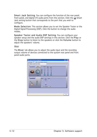
![5.3 Software information
Most of the applications in the support CD have wizards that will
conveniently guide you through the installation. View the online help or
readme file that came with the software application for more information.
5.3.1 ASUS MyLogo2™
The ASUS MyLogo2™ utility lets you customize the boot logo. The boot
logo is the image that appears on screen during the Power-On-Self-Tests
(POST). The ASUS MyLogo2™ is automatically installed when you install the
A S U S U p d a t e utility from the support CD. See section “5.2.3 Utilities
menu” for details.
• Before using the ASUS MyLogo2™, use the AFUDOS utility to make a
copy of your original BIOS file, or obtain the latest BIOS version from
the ASUS website. See section “4.1.2 AFUDOS utility”.
• Make sure that the BIOS item F u l l S c r e e n L o g o is set to
[Enabled] if you wish to use ASUS MyLogo2. See section “4.6.2
Boot Settings Configuration”.
• You can create your own boot logo image in GIF, JPG, or BMP file
formats.
To launch the ASUS MyLogo2™:
1. Launch the ASUS Update utility. Refer to section “4.1.4 ASUS Update
utility” for details.
2. Select O p t i o n s from the drop down menu, then click N e x t
t.
3. Check the option L a u n c h M y L o g o t o r e p l a c e s y s t e m b o o t
l o g o b e f o r e f l a s h i n g B I O S then click N e x t
S, t.
4. Select U p d a t e B I O S f r o m a f i l e from the drop down menu, then
click N e x tt.
5. When prompted, locate the new
BIOS file, then click N e x t The t.
ASUS MyLogo2 window appears.
6. From the left window pane, select
the folder that contains the image
you intend to use as your boot
logo.
5-8 Chapter 5: Software support](https://image.slidesharecdn.com/e1968p5ad2-edeluxe-110605220147-phpapp01/85/E1968-p5ad2-e-deluxe-122-320.jpg)
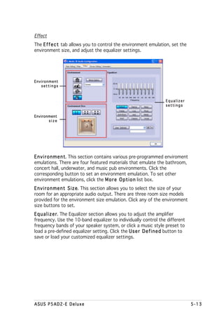
![Intel® Application Accelerator RAID Option ROM Utility
The Intel® Application Accelerator RAID Option ROM utility allows you to
create RAID 0 and RAID 1 set(s) from SATA hard disk drives that are
connected to the SATA connectors supported by the motherboard
Southbridge chip.
To enter the Intel® Application Accelerator RAID Option ROM utility:
1. Turn on the system after installing all the SATA hard disk drives.
2. During POST, press <Ctrl+I> to display the utility main menu.
Intel(R) Application Accelerator RAID Option ROM v4.0.0.6211
Copyright(C) 2003-04 Intel Corporation. All Rights Reserved.
[ MAIN MENU ]
1. Create RAID Volume
2. Delete RAID Volume
3. Reset Disks to Non-RAID
4. Exit
[ DISK/VOLUME INFORMATION ]
RAID Volumes:
None defined.
Non-RAID Disks:
Port Drive Model Serial # Size Type/Status (Vol ID)
0 ST380013AS xxxxxxxx 74.5GB Non-RAID Disk
1 ST380013AS xxxxxxxx 74.5GB Non-RAID Disk
[ ]-Select [ESC] Exit [Enter]-Select Menu
The RAID BIOS setup screens shown in this section are for reference
only, and may not exactly match the items on your screen.
At the bottom of the screen are the navigation keys. These keys allow
you to move through the menus and select the menu options.
[ ]-Change [TAB]-Next [ESC] Previous Menu [Enter]-Select
5-18 Chapter 5: Software support](https://image.slidesharecdn.com/e1968p5ad2-edeluxe-110605220147-phpapp01/85/E1968-p5ad2-e-deluxe-132-320.jpg)
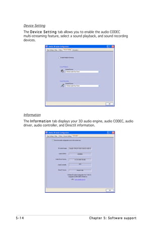
![Creating a RAID 0 set (striped)
To create a RAID 0 set:
1. From the utility main menu, select [ 1 . C r e a t e R A I D V o l u m e ]
],
then press <Enter>. The following screen appears.
Intel(R) Application Accelerator RAID Option ROM v4.0.0.6211
Copyright(C) 2003-04 Intel Corporation. All Rights Reserved.
[ CREATE ARRAY MENU ]
Name: RAID_Volume1
RAID Level: RAID0(Stripe)
Disks: Select Disk
Strip Size: 128KB
Capacity: 149.0GB
[ HELP ]
Enter a string between 1 and 16 characters in length taht can be used
to uniquely identify the RAID volume. This name is case sensitive and
can not contain special characters.
[ ]-Change [TAB]-Next [ESC] Previous Menu [Enter]-Select
2. Enter a name for the RAID 0 set, then press <Enter>.
3. Use the up or down arrow keys to move to the R A I D L e v e l item.
4. When the R A I D L e v e l item is highlighted, press the up or down
arrow key to select R A I D 0 then press <Enter>.
0,
5. Use the up or down arrow keys to move to the S t r i p e S i z e option.
6. When the S t r i p e S i z e item is highlighted, press the up or down
arrow keys to select the stripe size for the RAID 0 array, then press
<Enter>.
The available stripe size values range from 8KB to 128KB. The default
stripe size is 128 KB. You must choose the stripe size value based on
the projected drive usage. For low disk usage, select 8 KB/16 KB. For
typical disk usage, select 64 KB. select 128KB for performance disk
usage.
T I P . For server systems, use of a lower array block size is
recommended. For multimedia computer systems used mainly for audio
and video editing, a higher array block size is recommended for optimum
performance.
ASUS P5AD2-E Deluxe 5-19](https://image.slidesharecdn.com/e1968p5ad2-edeluxe-110605220147-phpapp01/85/E1968-p5ad2-e-deluxe-133-320.jpg)
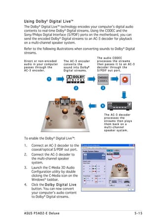
![Creating a RAID 1 set (mirrored)
To create a RAID 1 set:
1. From the utility main menu, select [ 1 . C r e a t e R A I D V o l u m e ]
],
then press <Enter>. The following screen appears.
Intel(R) Application Accelerator RAID Option ROM v4.0.0.6211
Copyright(C) 2003-04 Intel Corporation. All Rights Reserved.
[ CREATE ARRAY MENU ]
Name: RAID_Volume1
RAID Level: RAID1(Mirror)
Disks: Select Disk
Strip Size: 128KB
Capacity: 149.0GB
[ HELP ]
Enter a string between 1 and 16 characters in length taht can be used
to uniquely identify the RAID volume. This name is case sensitive and
can not contain special characters.
[ ]-Change [TAB]-Next [ESC] Previous Menu [Enter]-Select
2. Enter a name for the RAID 1 set, then press <Enter>.
3. Use the up or down arrow keys to move to the R A I D L e v e l item.
4. When the R A I D L e v e l item is highlighted, press the up or down
arrow key to select R A I D 1 then press <Enter>. The C r e a t e
1,
V o l u m e prompt appears.
5. On the C r e a t e V o l u m e prompt, press <Enter> to create the array.
6. Press <Y> when this query window appears.
WARNING: ALL DATA ON SELECTED DISK WILL BE LOST.
Are you sure you want to create this volume (Y/N)
7. Select [4 . E x i t then press <Enter> to exit the RAID configuration
4 t],
utility. Press <Y> when the utility displays a confirmation window.
5-20 Chapter 5: Software support](https://image.slidesharecdn.com/e1968p5ad2-edeluxe-110605220147-phpapp01/85/E1968-p5ad2-e-deluxe-134-320.jpg)
![Deleting a RAID set
Take caution when deleting a RAID set. You will lose all data on the hard
disk drives when you delete a RAID set.
To delete a RAID set:
1. From the utility main menu, select [ 2 . D e l e t e R A I D V o l u m e ] then
],
press <Enter> to display the following screen.
Intel(R) Application Accelerator RAID Option ROM v4.0.0.6211
Copyright(C) 2003-04 Intel Corporation. All Rights Reserved.
[ DELETE ARRAY MENU ]
Name Level Drives Capacity Status Bootable
RAID_Volume1 RAID0(Stripe) 2 149.0GB Normal Yes
[ HELP ]
Deleting a volume will destroy the volume data on the drive(s) and
cause any member disks to become available as non-RAID disks.
WARNING: EXISTING DATA WITHIN THIS VOLUME WILL BE LOST AND NON-RECOVERABLE
[ ]-Select [<ESC>]-Previous Menu [<DEL>]-Delete Volume
2. Use the up or down arrow keys to select the RAID set you want to
delete, then press <Del>.
3. Press <Del> to delete the RAID volume. A confirmation window
appears.
[ VOLUME DELETE VERIFICATION ]
ALL DATA IN THE VOLUME WILL BE LOST!!
Are you sure you want to delete volume "RAID_Volume0"? (Y/N)
4. Press <Y> to delete the RAID set; otherwise, press <N> to return to
the utility main menu.
ASUS P5AD2-E Deluxe 5-21](https://image.slidesharecdn.com/e1968p5ad2-edeluxe-110605220147-phpapp01/85/E1968-p5ad2-e-deluxe-135-320.jpg)
![Resetting a RAID set hard disks drive
Take caution before you reset a RAID volume HDD to non-RAID. Resetting
a RAID volume HDD deletes all internal RAID structure on the drive.
To reset a RAID set hard disk drive:
1. From the utility main menu, select [ 3 . R e s e t D i s k s t o N o n - R A I D ]
],
then press <Enter> to display the following screen.
[ RESET RAID DATA ]
Resetting RAID data will remove the internal RAID structures
from the selected RAID disks. By removing these structures
the drive will revert back to a Non-RAID disk.
WARNING: Resetting a disk causes all data on the disk to be lost.
Port Drive Model Serial # Size Status
0 STXXXXXXXXX XXXXXXXX XX.0GB Member Disk
1 STXXXXXXXXX XXXXXXXX XX.0GB Member Disk
Select the disk that should be reset
[ ]-Previous/Next [Space]-Selects [Enter]-Selection Complete
2. Use the up or down arrow keys to highlight the RAID set drive you
want to reset, then press <Space> to select.
3. Press <Enter> to reset the RAID set drive. A confirmation window
appears.
4. Press <Y> to reset the drive; otherwise, press <N> to return to the
utility main menu.
5. Follow steps 2 to 4 to select and reset other RAID set drives.
5-22 Chapter 5: Software support](https://image.slidesharecdn.com/e1968p5ad2-edeluxe-110605220147-phpapp01/85/E1968-p5ad2-e-deluxe-136-320.jpg)
![5.4.3 ITE® 8212F RAID configurations
The ITE® 8212F IDE RAID controller supports RAID 0, RAID 1, RAID 0+1 and
JBOD configurations. Use the IT8212 Setup Utility to create a disk array.
Setting the IDE RAID item in BIOS
You must set the IDE RAID item in the BIOS Setup before you can create an
IDE RAID set(s). To do this:
1. Enter the BIOS Setup during POST.
2. Go to the A d v a n c e M e n u select O n b o a r d D e v i c e s
u,
C o n f i g u r a t i o n then press <Enter>.
n,
3. Select the item I T E 8 2 1 2 F C o n t r o l l e r press <Enter>, then select
r,
R A I D M o d e from the configuration options.
You can not enter the ITE® 8212F Setup Utility when you set the
I T E 8 2 1 2 F C o n t r o l l e r option to [IDE Mode] or [Disabled].
5. Save your changes, then exit the BIOS Setup.
I T E® 8212F Setup Utility
To enter the ITE® 8212F Setup Utility:
1. Restart the computer. During POST, the ITE8212F controller
automatically scans for IDE devices attached to the IDE RAID
connectors.
2. When prompted, press <Ctrl+F> or <Ctrl+E> to display the utility main
menu.
IT8212 Setup Utility (C)Copyright 2002-2004 ITE, Inc.
[MAIN MENU]
Auto Configuration...........[ 1 ]
Define RAID..................[ 2 ]
Delete RAID..................[ 3 ]
Rebuild RAID.................[ 4 ]
RAID Card Configuration......[ 5 ]
[1]..[5] Select [ESC] Exit
The navigation keys on the bottom of the screen allow you to move
through the menus, select from the menu options, or exit the utility.
ASUS P5AD2-E Deluxe 5-23](https://image.slidesharecdn.com/e1968p5ad2-edeluxe-110605220147-phpapp01/85/E1968-p5ad2-e-deluxe-137-320.jpg)
![Auto-configuring a RAID array
The auto-configuration feature allows the utility to auto-configure the IDE
RAID hard disk drives depending on the selected RAID type.
To auto-configure a RAID set:
1. Press <1> from the utility main menu to display the following screen.
IT8212 Setup Utility (C)Copyright 2002-2004 ITE, Inc.
[ Auto Configuration Menu ]
Setup Array Type as: RAID 0
[ Array Configuration ]
RAID Mode................................ Stripe
Un-used Drive(s)......................... 4
Drive(s) in Array........................ 0
Array Capacity (size in MB).............. 8056
→ ←
[→,←,Space] Change Option [CTRL-Y] Save [ESC] Exit
2. Press the left/right arrow keys or the space bar to select a RAID type
from the S e t u p A r r a y T y p e a s field.
When you select a RAID type, the utility auto-configures the hard disk
drives and displays the RAID settings on screen.
3. Press <Ctrl+Y> to save the RAID configuration.
4. Press <Esc> to exit the utility.
5-24 Chapter 5: Software support](https://image.slidesharecdn.com/e1968p5ad2-edeluxe-110605220147-phpapp01/85/E1968-p5ad2-e-deluxe-138-320.jpg)
![Defining a RAID array
This option allows you to define the RAID set(s).
To define a RAID set(s):
1. Press <2> from utility main menu. The following screen appears.
2. Press the up/down arrow keys or the space bar to select a RAID set
you want to define, then press <Enter>.
IT8212 Setup Utility (C)Copyright 2002-2004 ITE, Inc.
[ Define RAID Menu ]
Array No Array Mode Drive No Size(MB) Status
Array 0 ---- ---- ----- -----
Array 1 ---- ---- ----- -----
Array 2 ---- ---- ----- -----
Array 3 ---- ---- ----- -----
∗ : Capacity (GB) ♦ : Bootable Array
↑
[↑] Up ↓
[↓] Down [Space] Boot Array [Enter] Select [ESC] Exit
3. Press the up/down arrow keys to move through the RAID set values.
4. Press the Space bar to adjust the RAID set values.
IT8212 Setup Utility (C)Copyright 2002-2004 ITE, Inc.
[ Define RAID Sub-Menu ]
Array No Array Mode Drive No Status
Array 0 Stripe 4 Functional
Block Size: 64KB
[ Drive Assignments]
Channel
ID Drive Name Size(MB) Assignment
Pri/D0 XXXXXXXXXXXXXX XXXXXX Y
Pri/D1 XXXXXXXXXXXXXX XXXXXX Y
Sec/D0 XXXXXXXXXXXXXX XXXXXX Y
Sec/D1 XXXXXXXXXXXXXX XXXXXX Y
∗ : Capacity (GB)
↑
[↑] Up ↓
[↓] Down [Space] Change Option [Ctrl-Y] Save [ESC] Exit
ASUS P5AD2-E Deluxe 5-25](https://image.slidesharecdn.com/e1968p5ad2-edeluxe-110605220147-phpapp01/85/E1968-p5ad2-e-deluxe-139-320.jpg)
![5. When finished, press <Ctrl+Y> to save RAID set configuration.
6. Press <Esc> to exit.
Deleting a RAID array
This option allows you to delete an existing RAID set(s).
Take caution when deleting a RAID set. You will lose all data on the hard
disk drives when you delete a RAID set.
To delete a RAID set(s):
1. Press <3> from utility main menu. The following screen appears.
IT8212 Setup Utility (C)Copyright 2002-2004 ITE, Inc.
[ Delete RAID Menu ]
Array No Array Mode Drive No Size(MB) Status
Array 0 Stripe 2 XXXXXX Functional
Array 1 Mirror 2 XXXX Functional
Array 2 ---- ---- ----- -----
Array 3 ---- ---- ----- -----
∗ : Capacity (GB) ♦ : Bootable Array
↑
[↑] Up ↓
[↓] Down [D] Delete [ESC] Exit
2. Press the up/down arrow keys to select the RAID set you want to
delete, then press <D>.
3. Press <Esc> to exit.
5-26 Chapter 5: Software support](https://image.slidesharecdn.com/e1968p5ad2-edeluxe-110605220147-phpapp01/85/E1968-p5ad2-e-deluxe-140-320.jpg)
![Rebuilding a RAID array
This option allows you to rebuild an existing RAID set. This option only
applies to RAID 1 (Mirrored) or RAID 0+1(Striped+Mirrored) sets.
To rebuild a RAID 1 or 0+1 set:
1. Press <4> from utility main menu. The following screen appears.
IT8212 Setup Utility (C)Copyright 2002-2004 ITE, Inc.
[ Rebuild RAID Menu ]
Array No Array Mode Drive No Size(MB) Status
Array 0 Stripe 4 XXXXXX Functional
Array 1 Mirror 2 XXXX Functional
Array 2 ---- ---- ----- -----
Array 3 ---- ---- ----- -----
∗ : Capacity (GB) ♦ : Bootable Array
↑
[↑] Up ↓
[↓] Down [Enter] Select [ESC] Exit
2. Use the up or down arrow keys to select a RAID array, then press
<Enter> to rebuild. The following screen appears.
IT8212 Setup Utility (C)Copyright 2002-2004 ITE, Inc.
[ Source Drive ]
Channel ID Drive Name Size (MB)
Pri/D1 XXXXXXXXXX XXXXX
[ Target Drive ]
Channel ID Drive Name Size (MB)
Sec/D1 XXXXXXXXXX XXXXX
[ Drive List]
Channel ID Drive Name Size (MB)
Pri/D1 XXXXXXXXXX XXXXX
Sec/D1 XXXXXXXXXX XXXXXX
∗ : Capacity (GB)
↑
[↑] Up ↓
[↓] Down [Enter] Select [ESC] Exit
3. Press the up/down arrow keys to select the drive you want to rebuild,
then press <Enter>.
4. Follow succeeding screen instructions to continue.
ASUS P5AD2-E Deluxe 5-27](https://image.slidesharecdn.com/e1968p5ad2-edeluxe-110605220147-phpapp01/85/E1968-p5ad2-e-deluxe-141-320.jpg)
![Viewing your RAID configuration
This option allows you to view the system RAID configuration and RAID
resources. You can also enable or disable the Auto-Rebuild function from
this menu.
To view your RAID configuration:
1. Press <5> from utility main menu. The following screen appears.
IT8212 Setup Utility (C)Copyright 2002-2004 ITE, Inc.
[ RAID Card Configuration ]
Auto-Rebuild: Enable
[ RAID Card Resource ]
Channel 0 Interrupt: B I/P Port: 0000AC00
Channel 1 Interrupt: B I/P Port: 0000A800
[ Drive Status ]
Channel Size Drive
ID Drive Name (MB) Array No Mode
Pri/D0 XXXXXXXXXXXXXX XXXXXX Array 0 U5
Pri/D1 XXXXXXXXXXXXXX XXXXXX Array 0 U2
Sec/D0 XXXXXXXXXXXXXX XXXXXX Array 0 U4
Sec/D1 XXXXXXXXXXXXXX XXXXXX Array 0 U6
∗ : Capacity (GB) Drive Mode: P = PIO, D = DMA, U = UDMA
→ ←
[→,←,Space] Change Option [ESC] Exit
2. View your RAID configuration from this menu, then press <Esc> to
exit the utility.
To enable/disable the Auto-Rebuild feature:
1. Use the left/right arrow keys or the space bar to enable or disable
the A u t o - R e b u i l d item.
2. Press <Esc> to exit the utility.
5-28 Chapter 5: Software support](https://image.slidesharecdn.com/e1968p5ad2-edeluxe-110605220147-phpapp01/85/E1968-p5ad2-e-deluxe-142-320.jpg)
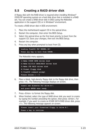
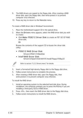

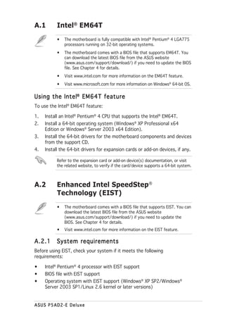
![A.2.2 Using the EIST
To use the EIST feature:
1. Turn on the computer, then enter the BIOS Setup.
2. Go to the Advanced Menu highlight CPU Configuration
Menu, Configuration,
then press <Enter>.
3. Set the Intel(R) SpeedStep Technology item to [Automatic],
then press <Enter>. See page 4-26 for details.
4. Press <F10> to save your changes and exit the BIOS setup.
5. After the computer restarts, right click on a blank space on the desktop,
then select Properties from the pop-up menu.
6. When the Display Properties
window appears, click the
Screen Saver tab.
7. Click the Power button on the
Monitor power section to open
the Power Options
Properties window.
8. On the Power schemes section,
click , then select any option
except Home/Office Desktop
or Always On On.
9. Click A p p l y then click O K
y, K.
10. Close the Display Properties
window.
After you adjust the power
scheme, the CPU internal
frequency slightly decreases
when the CPU loading is low.
The screen displays and procedures may vary depending on the
operating system.
A-2 Appendix: CPU features](https://image.slidesharecdn.com/e1968p5ad2-edeluxe-110605220147-phpapp01/85/E1968-p5ad2-e-deluxe-148-320.jpg)
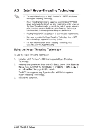


![Rutina diaria[2] cludia](https://cdn.slidesharecdn.com/ss_thumbnails/rutinadiaria2cludia-110712210014-phpapp02-thumbnail.jpg?width=640&height=640&fit=bounds)


