This document provides an overview and instructions for installing and using Hitachi Storage Navigator Modular 2 (Navigator 2). It includes information on:
- Key features of Navigator 2 and how it integrates with Hitachi storage systems
- System requirements and pre-installation steps
- Installing Navigator 2 on Windows, Solaris, and Linux operating systems
- Performing initial configuration steps like adding arrays, creating volumes, and mapping volumes to hosts
- Using basic Navigator 2 interface elements and functions
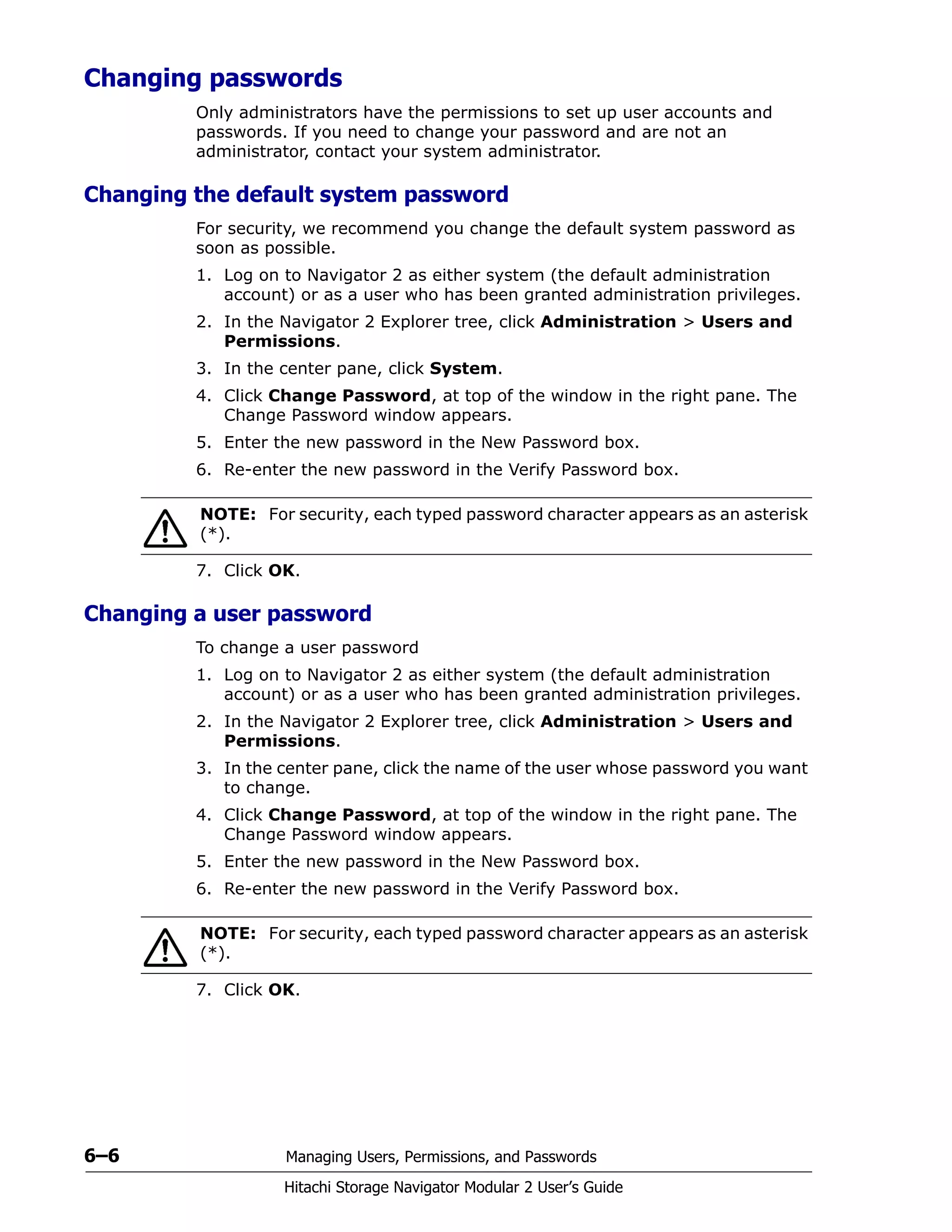
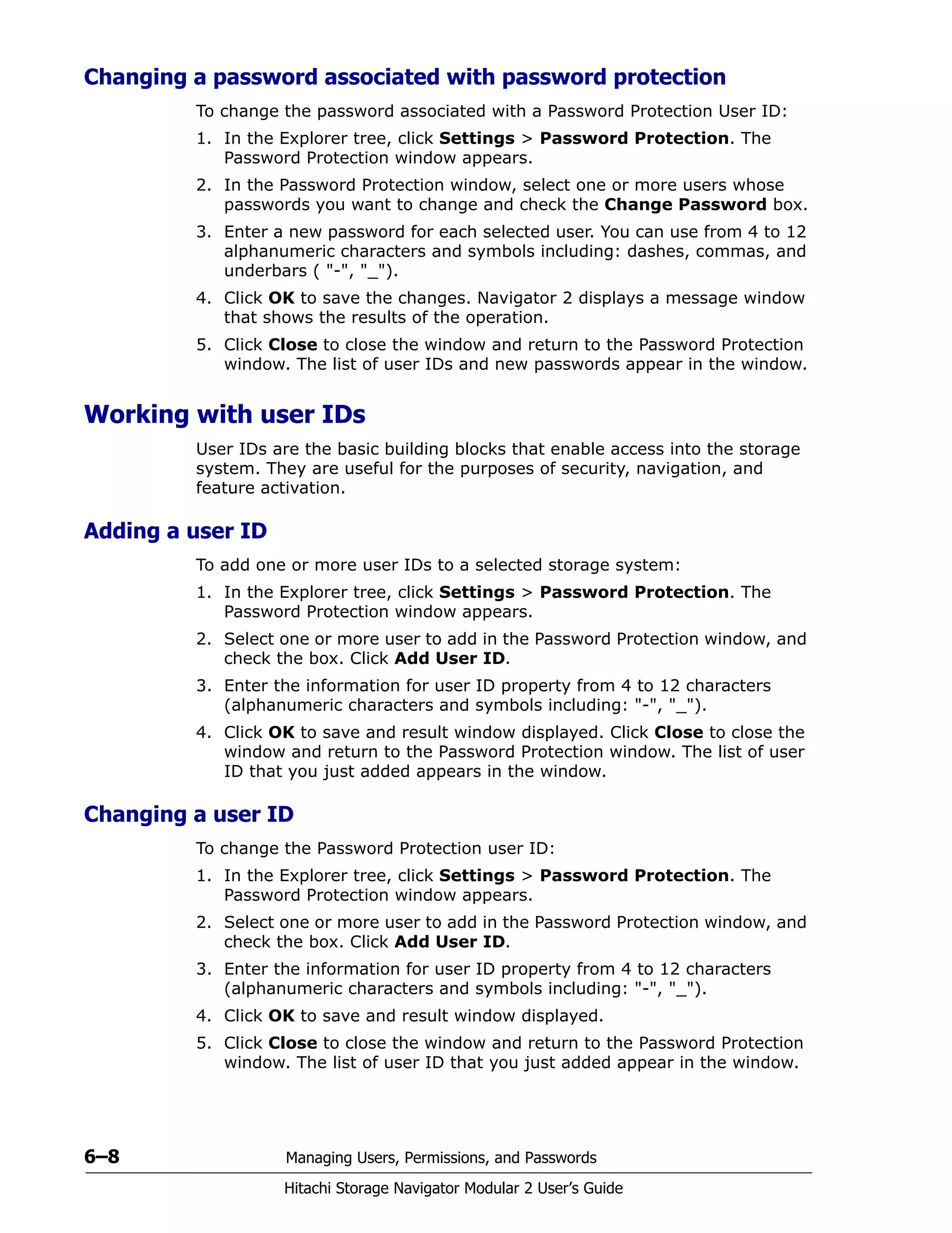
- Managing users, permissions, and passwords
- Providing a quick tour of common Navigator 2 activities


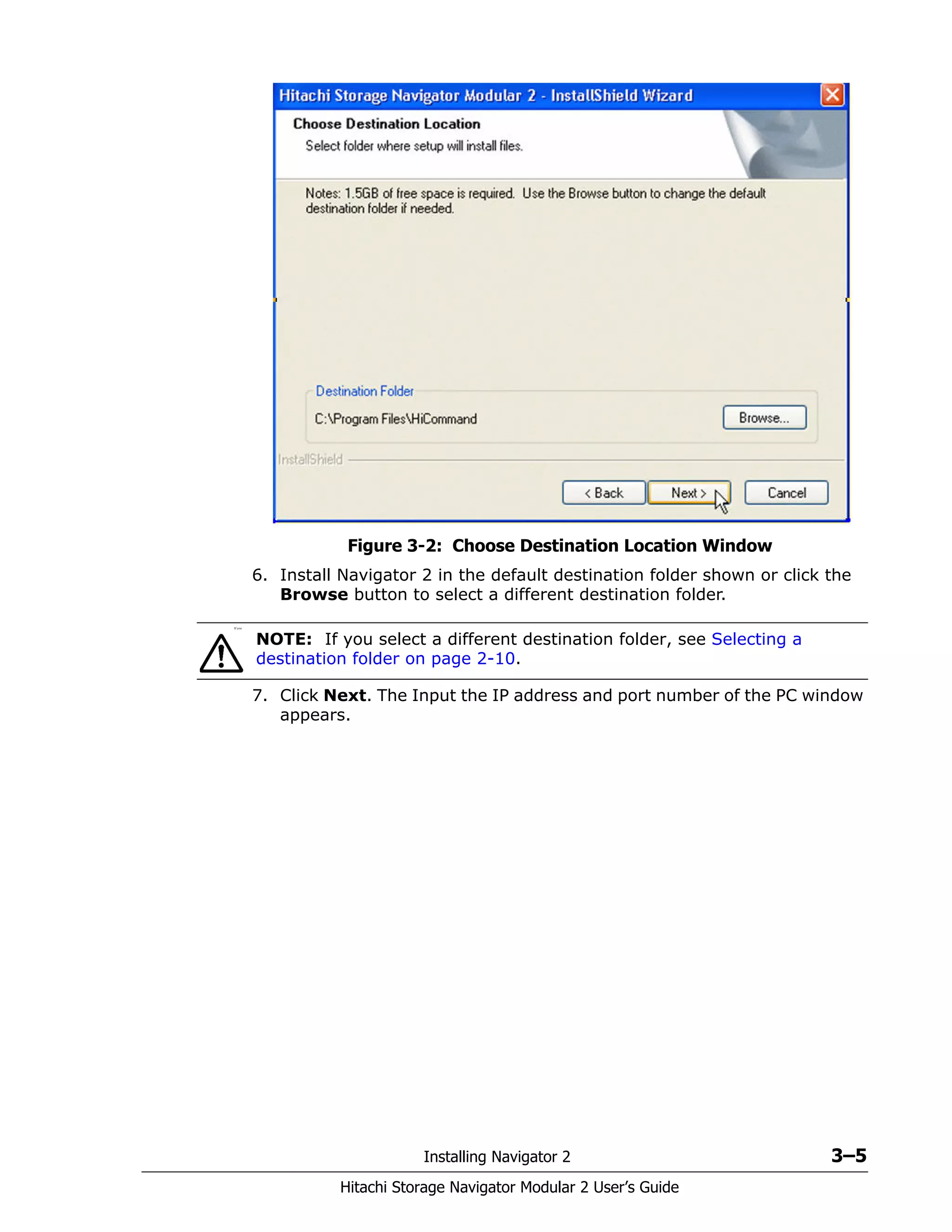
![Preface xiii
Hitachi Storage Navigator Modular 2 User’s Guide
The following typographic conventions are used in this document.
Accessing product documentation
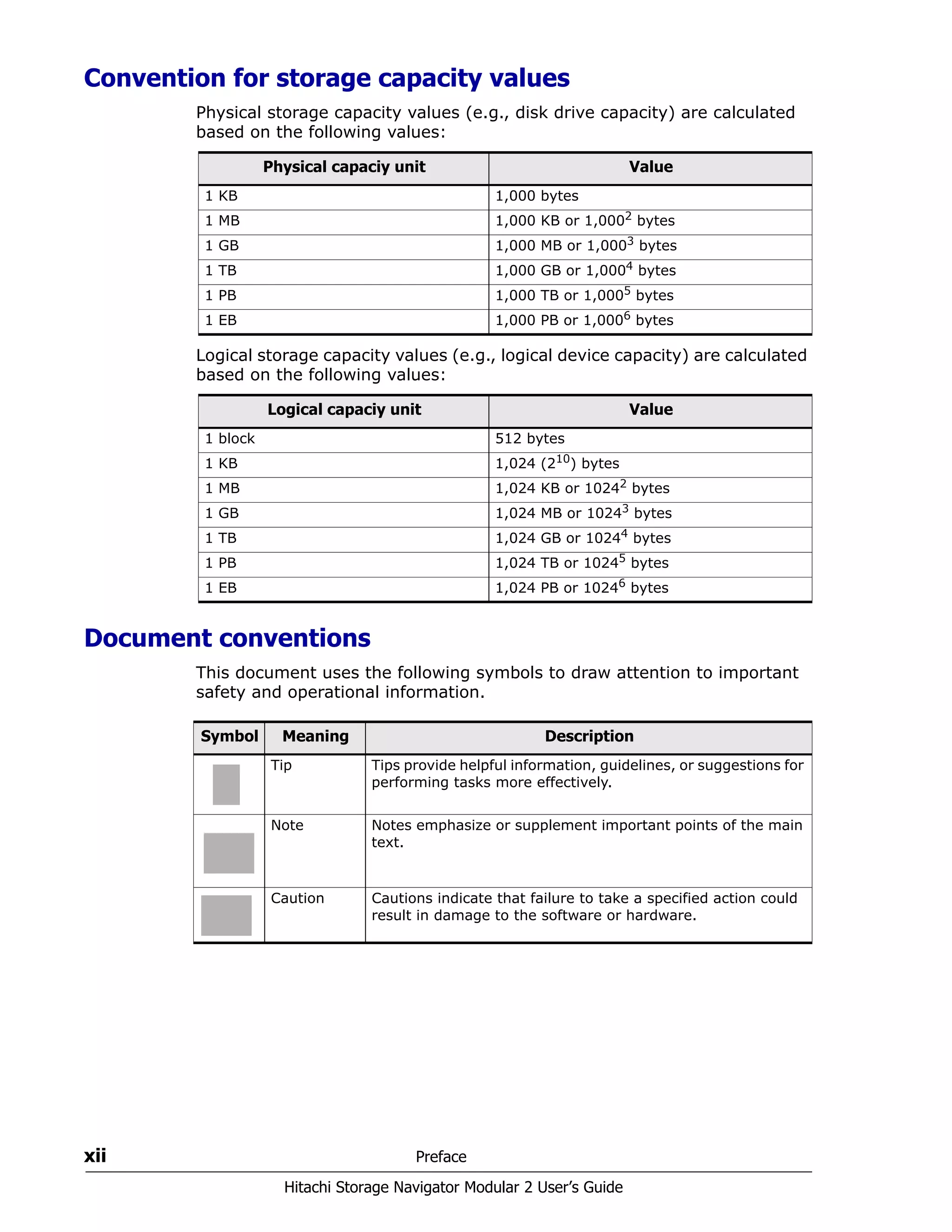
The AMS 2000 Family user documentation is available on the Hitachi Data
Systems Portal: https://portal.hds.com. Please check this site for the most
current documentation, including important updates that may have been
made after the release of the product.
This documentation set consists of the following documents.
Release notes
• Adaptable Modular Storage System Release Notes
• Storage Navigator Modular 2 Release Notes
Convention Description
Bold Indicates text on a window, other than the window title, including
menus, menu options, buttons, fields, and labels. Example: Click OK.
Italic Indicates a variable, which is a placeholder for actual text provided by
the user or system. Example: copy source-file target-file
Angled brackets (< >) are also used to indicate variables.
screen/code Indicates text that is displayed on screen or entered by the user.
Example: # pairdisplay -g oradb
< > angled
brackets
Indicates a variable, which is a placeholder for actual text provided by
the user or system. Example: # pairdisplay -g <group>
Italic font is also used to indicate variables.
[ ] square
brackets
Indicates optional values.
Example: [ a | b ] indicates that you can choose a, b, or nothing.
{ } braces Indicates required or expected values. Example: { a | b } indicates that
you must choose either a or b.
| vertical bar Indicates that you have a choice between two or more options or
arguments. Examples:
[ a | b ] indicates that you can choose a, b, or nothing.
{ a | b } indicates that you must choose either a or b.
underline Indicates the default value. Example: [ a | b ]
Please read the release notes before installing and/or using this product.
They may contain requirements and/or restrictions not fully described in
this document, along with updates and/or corrections to this document.](https://image.slidesharecdn.com/bb72093e-f266-4301-a68b-3cbe334cba97-160202020606/75/MK-99DF8208-03-13-2048.jpg)


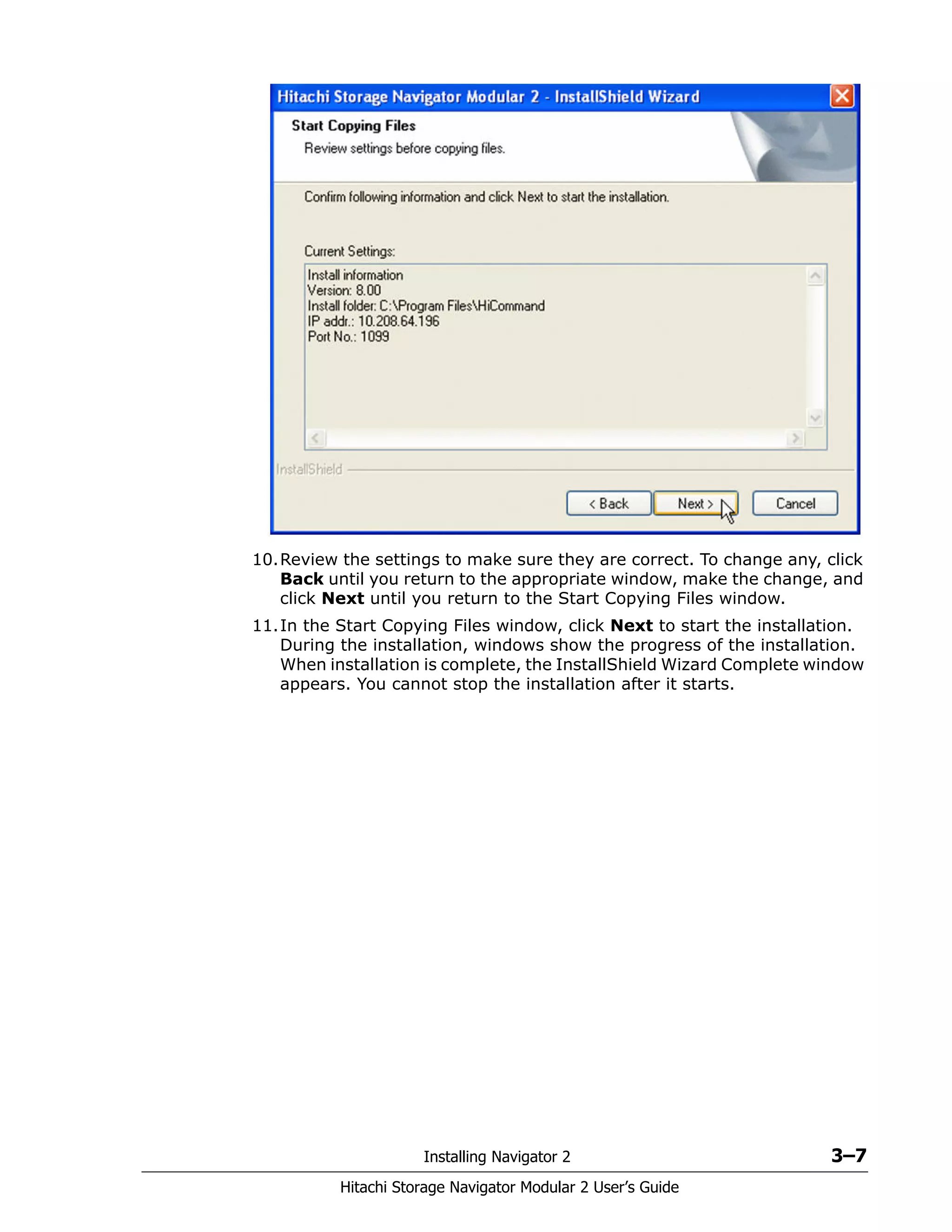
![Preinstallation Information 2–11
Hitachi Storage Navigator Modular 2 User’s Guide
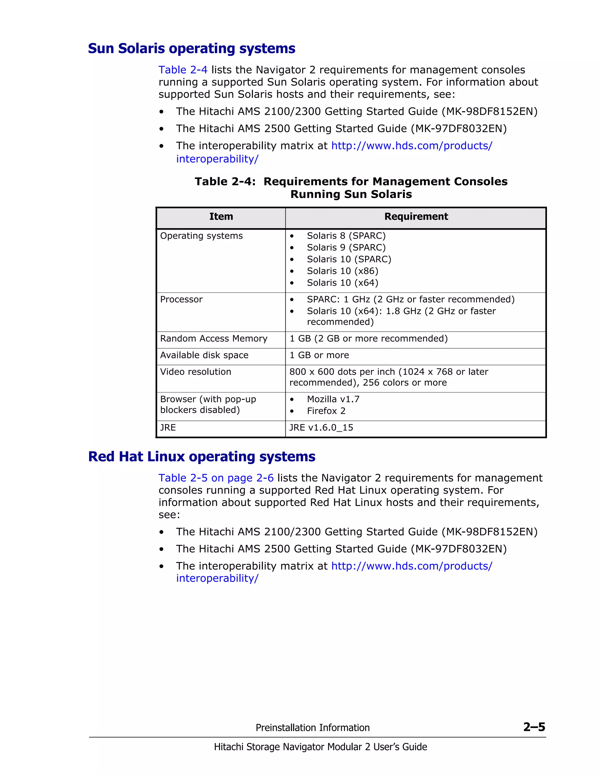
Solaris and Linux operating systems
Installation prerequisites
Before installing Navigator 2 on a management console running one of the
supported Solaris and Linux operating systems in Table 2-3 on page 2-4:
• Log on as a root user.
• If /opt exists, the normal directory is required, not the symbolic link.
However, the file system can be mounted as a mount point.
• For Solaris v10 (SPARC), apply the appropriate patch.
• Apply patch 120664-xx (where xx is 01 or later).
• Apply patch 127127-xx (where xx is 11 or later).
• Do not apply patches 127111-02 and 127111-03.
• For Solaris v10 (x64), apply patch 120665-xx (where xx is 01 or later)
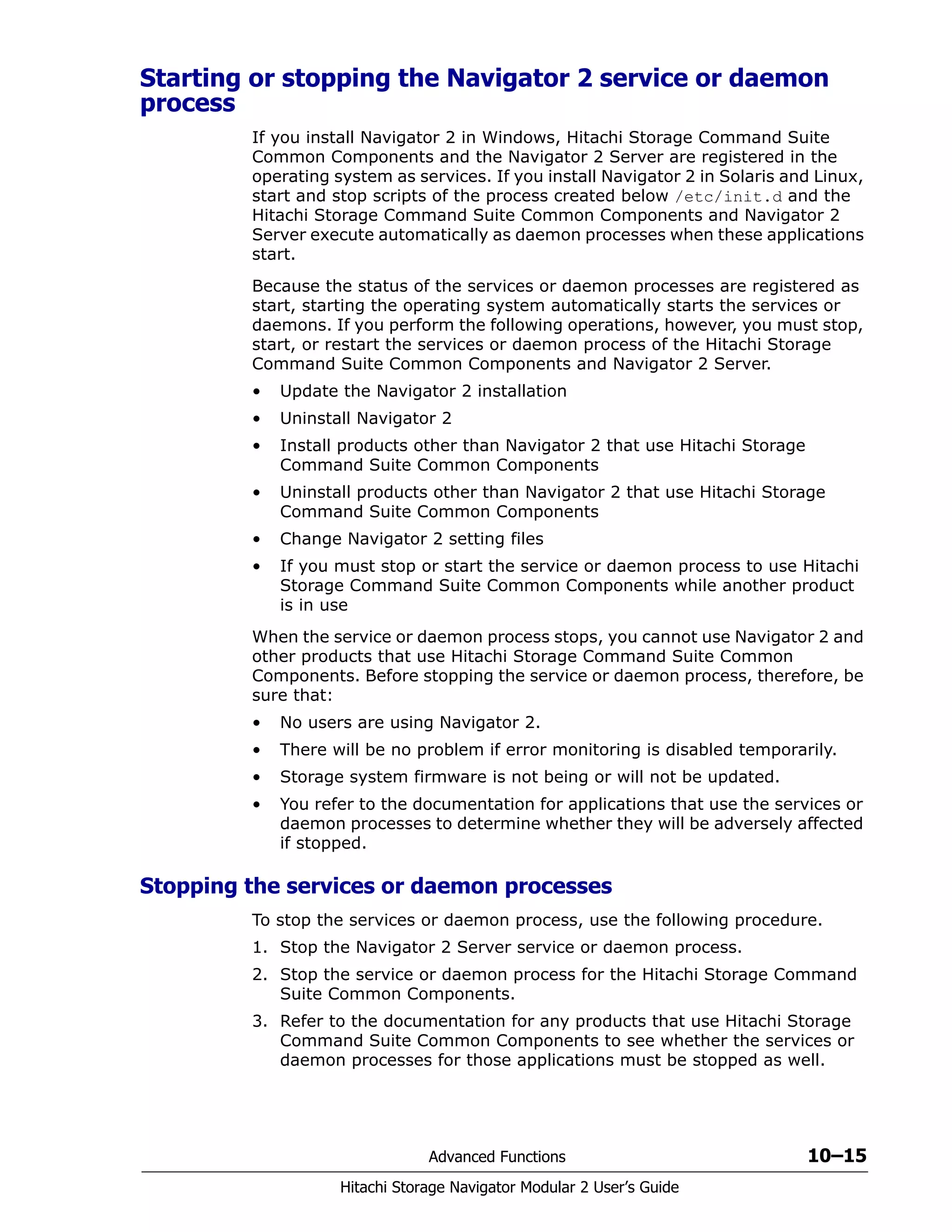
• For Linux, set the kernel parameters described in the following
sections.
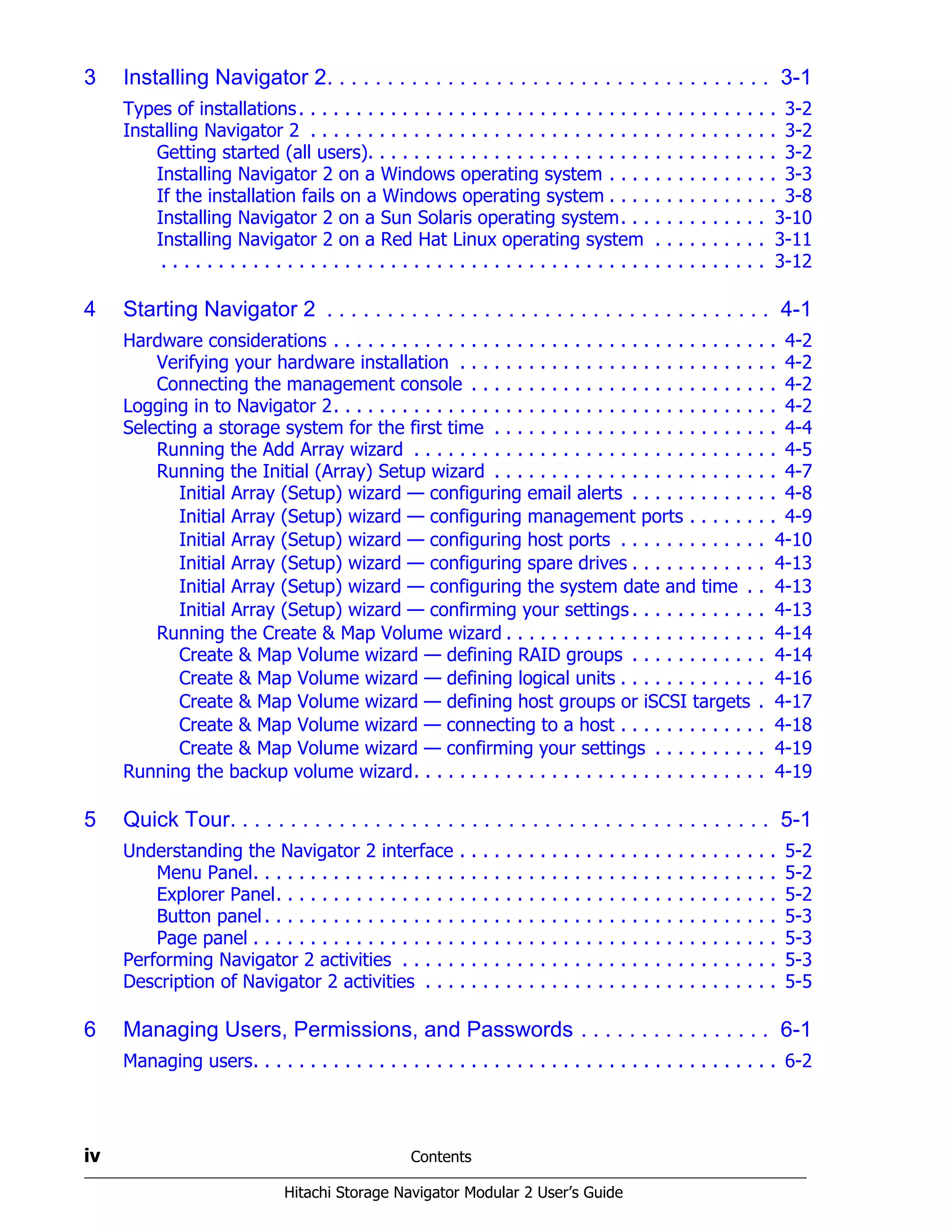
Setting Linux kernel parameters
To set the Linux kernel parameters:
1. Back up the kernel parameters setting files /etc/sysctl.conf and
/etc/security/limits.conf.
2. Open the kernel parameters setting file /etc/sysctl.conf with a text
editor and change the following settings. The parameters are specified
using the syntax [name of parameter]=[value]. Four values separated
by space are specified in kernel.sem. Your parameter settings must not
exceed the maximum value for the operating system.
The following example shows how to check whether the value is valid for
kernel.shmmax:
cat /proc/sys/kernel/shmmax
Table 2-7 provides recommended values and calculation methods for
each kernel type.
Table 2-7: Kernel Type Recommended Values
Parameter Name
Recommended Value
Calculation Method
Navigator 2 Database
kernel.shmmax 11542528 200000000 Maximum value in current and
two recommended values.
kernel.shmall 22418432 22418432 Total value of current and
recommended values.](https://image.slidesharecdn.com/bb72093e-f266-4301-a68b-3cbe334cba97-160202020606/75/MK-99DF8208-03-37-2048.jpg)
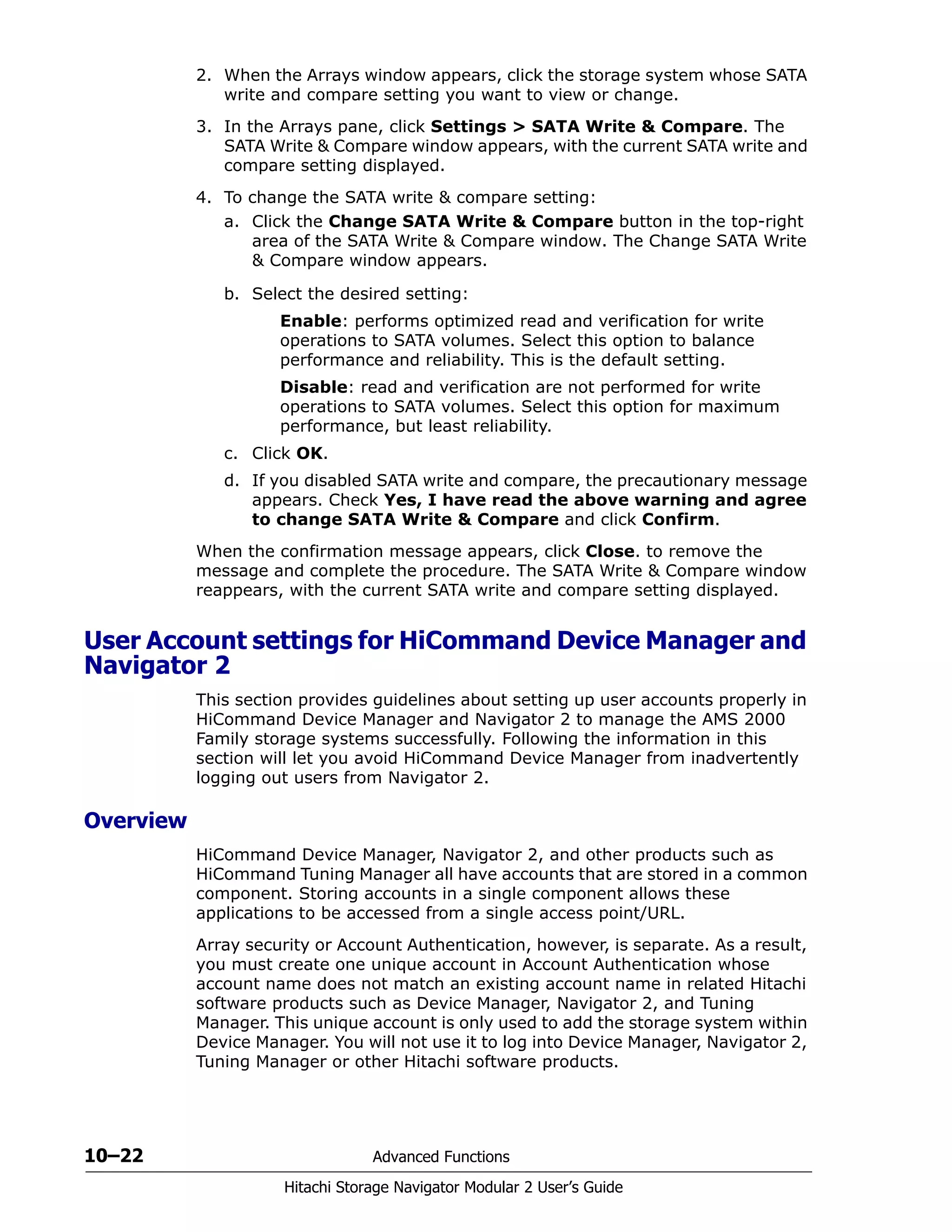
![2–12 Preinstallation Information
Hitachi Storage Navigator Modular 2 User’s Guide
Open the kernel parameters setting file /etc/security/limits.conf
with a text editor and change the following settings. The parameters are
specified using the syntax [domain] [type] [name of parameter]
[value]. Domains are specified for “*”. The types are specified for both
“soft” and “hard.” The soft value must not exceed the hard value. Then,
the parameter must not exceed the maximum value that the operating
system specifies. Table 2-8 shows the recommended values and calculation
methods for the kernel parameter types.
3. Reboot the host.
Setting Solaris v8 or Solaris v9 kernel parameters
When installing Navigator 2 on a management console running Solaris v8
or Solaris v9, set the Solaris kernel parameters.
1. Back up the kernel parameters setting file /etc/system.
kernel.shmmni 0 2000 The larger value of:
• The total value of current
and Navigator 2
recommended value.
• The database
recommended value.
kernel.threads-max 184 574
kernel.msgmni 32 32
kernel.sem
(Second parameters)
80 7200
kernel.sem
(Forth parameters)
9 1024
fs.file-max 53898 53898
Table 2-7: Kernel Type Recommended Values (Continued)
Parameter Name
Recommended Value
Calculation Method
Navigator 2 Database
Table 2-8: Kernel Parameter Recommended Values
Parameter Name
Recommended Value
Calculation Method
Navigator 2 Database
nofile 572 1344 The larger value of:
• The total value of current
and Navigator 2
recommended value.
• The database
recommended value.
nproc 165 512](https://image.slidesharecdn.com/bb72093e-f266-4301-a68b-3cbe334cba97-160202020606/75/MK-99DF8208-03-38-2048.jpg)


![3–10 Installing Navigator 2
Hitachi Storage Navigator Modular 2 User’s Guide
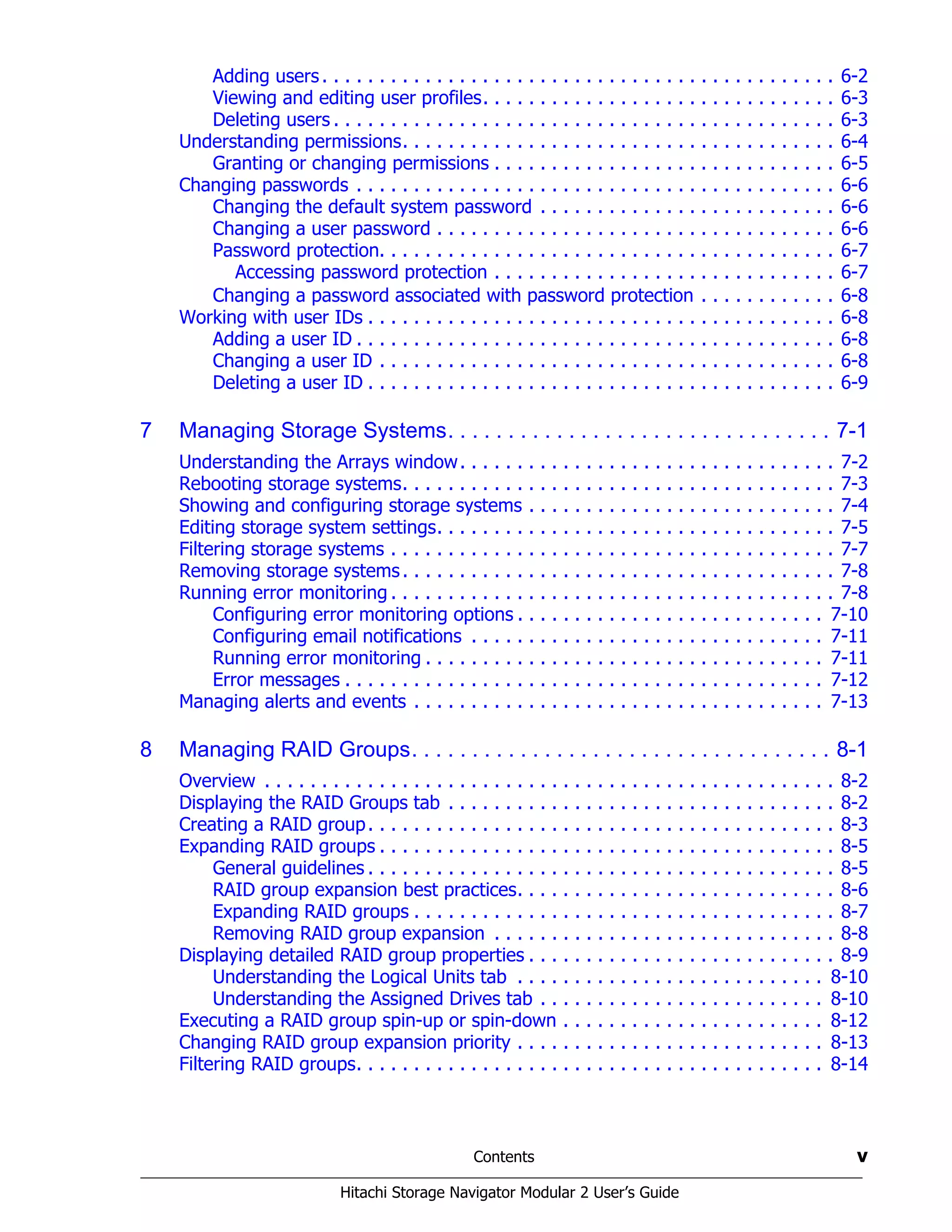
Installing Navigator 2 on a Sun Solaris operating system
The following procedure describes how to install Navigator 2 on a Navigator
2-supported version of Sun Solaris. Before you perform the following
procedure, be sure that the following directories have at least the minimum
of amount of available disk space shown in Table 3-1.
To perform a new installation for Sun Solaris:
1. Insert the Hitachi Storage Navigator Modular 2 installation CD-ROM into
the management console’s CD/DVD-ROM drive.
2. Mount the CD-ROM on the file system. The mount destination is /cdrom.
3. Create a temporary directory with sufficient free space (more than 600
MB) on the file system and expand the compressed files. The temporary
directory is /temporary here.
4. In the console, issue the following command lines. In the last command,
XXXX varies with the version of Navigator 2.
5. In the console, issue the following command line:
Table 3-1: Solaris Directories and Disk Space
Directory Minimum Available Disk Space Required
/opt/HiCommand 1.5 GB
/var/opt/HiCommand 1.0 GB
/var/tmp 1.0 GB
NOTE: If the CD-ROM cannot be read, copy the files install-hsnm2.sh
and HSNM2-XXXX-S-GUI.tar.gz to a file system that the host can
recognize.
mkdir /temporary
cd /temporary
gunzip < /cdrom/HSNM2-XXXX-S-GUI.tar.gz | tar xf -
/temporary/install-hsnm2.sh -a [IP address] -p [port number]](https://image.slidesharecdn.com/bb72093e-f266-4301-a68b-3cbe334cba97-160202020606/75/MK-99DF8208-03-50-2048.jpg)
![Installing Navigator 2 3–11
Hitachi Storage Navigator Modular 2 User’s Guide
In this command line:
• [IP address] is the IP address used to access Navigator 2 from
your browser. When entering an IP address, do not specify
127.0.0.1 and localhost. For DHCP environments, specify the host
name (computer name).
• [port number] is the port number used to access Navigator 2
from your browser. The default, port number is 1099. If you use it,
you can omit the –p option from the command line.
6. Proceed to Chapter 4, Starting Navigator 2 for instructions about logging
in to Navigator 2.
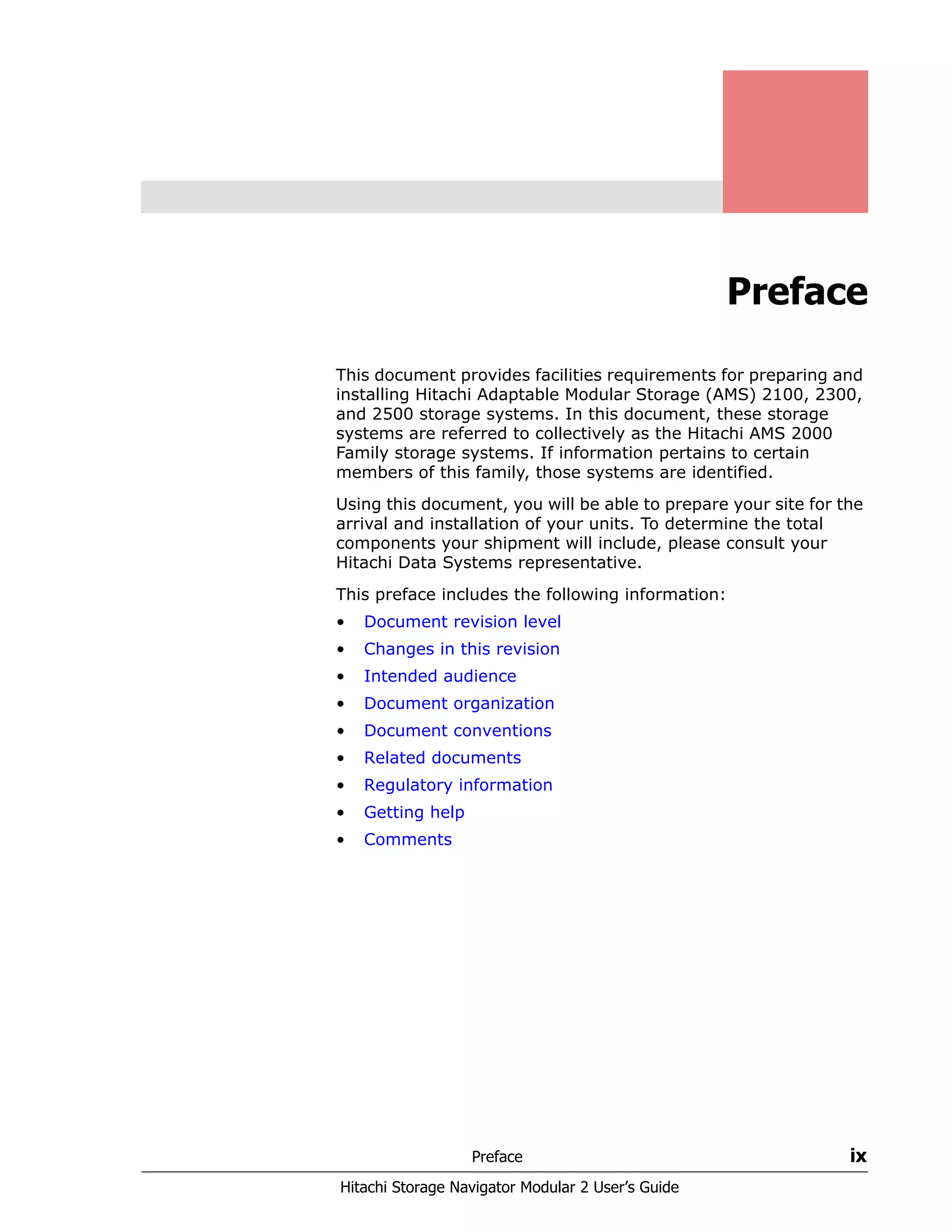
Installing Navigator 2 on a Red Hat Linux operating system
To install Navigator 2 on a Navigator 2-supported version of Red Hat Linux,
perform the following procedure.
1. Insert the Hitachi Storage Navigator Modular 2 installation CD-ROM into
the management console’s CD/DVD-ROM drive.
2. Mount the CD-ROM on the file system. The mount destination is /cdrom.
3. In the console, issue the following command line:
In this command line:
• [IP address] is the IP address used to access Navigator 2 from
your browser. When entering an IP address, do not specify
127.0.0.1 and localhost. For DHCP environments, specify the host
name (computer name).
TIP: For environments using DHCP, enter the host name (computer name)
for the IP address.
NOTE: If the CD-ROM cannot be read, copy the files install-hsnm2.sh
and HSNM2-XXXX-L-GUI.rpm to a file system that the host can recognize.
sh /cdrom/install-hsnm2.sh -a [IP address] -p [port number]](https://image.slidesharecdn.com/bb72093e-f266-4301-a68b-3cbe334cba97-160202020606/75/MK-99DF8208-03-51-2048.jpg)
![3–12 Installing Navigator 2
Hitachi Storage Navigator Modular 2 User’s Guide
• [port number] is the port number used to access Navigator 2
from your browser. The default port number is 1099. If you use it,
you can omit the –p option from the command line.
4. Proceed to Chapter 4, Starting Navigator 2 for instructions about logging
in to Navigator 2.](https://image.slidesharecdn.com/bb72093e-f266-4301-a68b-3cbe334cba97-160202020606/75/MK-99DF8208-03-52-2048.jpg)
![4–2 Starting Navigator 2
Hitachi Storage Navigator Modular 2 User’s Guide
Hardware considerations
Before you log in to Navigator 2, observe the following considerations.
Verifying your hardware installation
Install your Hitachi Data Systems storage system according to the
instructions in the system’s hardware guide. Then verify that your Hitachi
Data Systems storage system is operating properly.
Connecting the management console
After verifying that your Hitachi Data Systems storage system is
operational, connect the management console on which you installed
Navigator 2 to the storage system’s management port(s).
Every controller on a Hitachi storage system has a 10/100BaseT Ethernet
management port labeled LAN. Hitachi storage systems equipped with two
controllers have two management ports, one for each controller. The
management ports let you configure the controllers using an attached
management console and the Navigator 2 software.
Your management console can connect to the management ports directly
using an Ethernet cable or through an Ethernet switch or hub. The
management ports support Auto-Medium Depedent Interface/Medium
Dependent Interface Crossover (Auto-MDI/MDIX) technology, allowing you
to use either standard (straight-through) or crossover Ethernet cables.
Use one of these methods to connect the management console to controller,
then power up the storage system.
Logging in to Navigator 2
The following procedure describes how to log in to Navigator 2. When
logging in, you can specify an IPv4 address or IPv6 address using a
nonsecure (http) or secure (https) connection to the Hitachi storage
system.
1. Launch a Web browser on the management console.
2. In the browser’s address bar, enter the IP address of the storage
system’s management port using IPv4 or IPv6 notation. You recorded
this IP address in Table C-1 on page C-1:
• IPv4 http example:
http://IP address:23015/StorageNavigatorModular/Login
• IPv4 https example:
https://IP address:23016/StorageNavigatorModular/Login
• IPv6 https example (IP address must be entered in brackets):
https://[IP address]:23015/StorageNavigatorModular/Login
TIP: You can attach a portable (“pocket”) hub between the management
console and storage system to configure both controllers in one procedure,
similar to using a switch.](https://image.slidesharecdn.com/bb72093e-f266-4301-a68b-3cbe334cba97-160202020606/75/MK-99DF8208-03-54-2048.jpg)


![Managing Users, Permissions, and Passwords 6–3
Hitachi Storage Navigator Modular 2 User’s Guide
Viewing and editing user profiles
In the Edit Profile window, you can modify the user’s full name, email
address, or description.
To edit a user profile:
1. Log on to Navigator 2 as either system (the default administration
account) or as a user who has been granted administration privileges.
2. In the Navigator 2 Explorer tree, click Administration > Users and
Permissions > Users. The Users window appears.
3. Click a user name, then click Edit Profile and make the desired
changes.
4. Click OK.
Deleting users
If you no longer need a user, you can delete the user from Navigator 2.
To delete a user:
1. Log on to Navigator 2 as either system (the default administration
account) or as a user who has been granted administration privileges.
2. In the Navigator 2 Explorer tree, click Administration > Users and
Permissions > Users. The Users window appears.
3. Click a user name, then click Delete User.
4. When a message asks whether you are sure you want to delete the
selected user, click OK to delete the user (or click Cancel to retain the
user).
Full Name Entering the user’s full name is optional. If you include it, enter
no more than 80 Basic Latin characters. Basic Latin characters
are the following characters (Unicode 0020 to 007E):
A-Z a-z 0-9 ! " # $ % & ' ( ) * + , - . / : ; < = > ? @ [ ] ^ _
` { | } ~ (space)
Note: You cannot use two or more dollar signs consecutively
(for example, $$ or $$$). The full name appears in the global
task bar area after a user logs in. If this item is omitted, the
user ID will be displayed in the global task bar area.
E-mail Address Type the user’s email address.
Description Type any optional description you want to include (for
example, the user’s job title). Entering a description for the
user is optional. If you enter a description, enter no more than
80 characters, using the character set allowed for the full
name.
Table 6-1: Adding Users (Continued)
Field Description](https://image.slidesharecdn.com/bb72093e-f266-4301-a68b-3cbe334cba97-160202020606/75/MK-99DF8208-03-85-2048.jpg)


![Advanced Functions 10–9
Hitachi Storage Navigator Modular 2 User’s Guide
The following shows an example of issuing this command line:
4. Type the following command line to create a certificate signing request
(CSR):
hcmdssslc req -config C:Program
FilesHiCommandBasehttpsdsslcbindemoCAsslc.cnf
-new -key c:cahttpsdkey.pem -out c:cahttpsd.csr
5. Submit the created CSR file (httpsd.csr in the above example) to the
The following shows an example of issuing this command line:
6. Submit the created CSR file (httpsd.csr in the above example) to the
CA and obtain the signed certificate.
hcmdssslc genrsa -out c:cahttpsdkey.pem 2048
Loading 'entropy' into random state - unable to load 'random state'
warning, not much extra random data, consider using the -rand option
Generating 2 prime RSA private key, 2048 bit long modulus
..................................................................++
+++
...........+++++
e is 65537 (0x10001)
Using configuration from C:Program
FilesHiCommandBasehttpsdsslcbindemoCA
sslc.cnf
You will be prompted to enter information to incorporate
into the certificate request.
This information is called a Distinguished Name or a DN.
There are many fields however some can remain blank.
Some fields have default values.
Enter '.', to leave the field blank.
-----
Country Name (2 letter code) []:us
State or Province Name (full name) []:California
Locality Name (eg, city) []:San Jose
Organization Name (eg, company) []:Hitachi
Organizational Unit Name (eg, section) []:Hitachi
Common Name (eg, YOUR name) []:Hitachi
Email Address []:
Please enter the following 'extra' attributes
to be sent with your certificate request
A challenge password []:
An optional company name []:
NOTE: If you do not submit the CSR file to or obtain the signed certificate
file from the CA, you can still create the certificate file with your signature
using the hcmdssslc command. However, a warning window appears when
the initial Navigator 2 window and subsequent window appear.](https://image.slidesharecdn.com/bb72093e-f266-4301-a68b-3cbe334cba97-160202020606/75/MK-99DF8208-03-145-2048.jpg)
![10–10 Advanced Functions
Hitachi Storage Navigator Modular 2 User’s Guide
7. To create a self-signed certificate file, type the following command line:
hcmdssslc x509 -in c:cahttpsd.csr -out c:canewcert.pem -reg -signkey
c:cahttpsdkey.pem -days 365
c:cahttpsd.csr: CSR to CA
c:canewcert.pem: self-signed certificate
c:cahttpsdkey.pem: key file
8. Using a text editor, open the file httpsd.conf in
<installation directory>Basehttpsdconf.
9. Delete the hash sign (#) from the following slanted lines, which are
commented out by default. Change the values of SSLCertificateFile
and SSLCertificateKeyFile:
a. For SSLCertificateFile, specify the signed certificate file obtained
from the CA.
b. For SSLCertificateKeyFile, specify the full path of the private key
file created earlier in this procedure.
The contents of the file are shown below:
10.Start the service for Navigator 2 (see Starting the Navigator 2 server
service or daemon process on page 10-20).
11.Start the service for Hitachi Storage Command Suite Common
Components (see Starting the Hitachi Storage Command Suite common
components on page 10-19).
12.If there are other products that use the Hitachi Storage Command Suite
Common Components, start the daemon process for those applications
(refer to the documentation for those applications).
SSLSessionCacheSize 0
#Listen 23016
#Listen [::]:23016
#<VirtualHost s1j-orca2xp:23016>
# ServerName s1j-orca2xp
# SSLEnable
# SSLProtocol SSLv3 TLSv1
# SSLRequireSSL
# SSLCertificateFile "C:/ca/httpsd.pem"
# SSLCertificateKeyFile "C:/ca/httpsdkey.pem"
# SSLCACertificateFile "C:/Program #Files/HiCommand/Base/httpsd/
conf/ssl/cacert/anycert.pem"
# SSLSessionCacheTimeout 3600
#</VirtualHost>](https://image.slidesharecdn.com/bb72093e-f266-4301-a68b-3cbe334cba97-160202020606/75/MK-99DF8208-03-146-2048.jpg)
![Advanced Functions 10–11
Hitachi Storage Navigator Modular 2 User’s Guide
Creating a private key on Solaris or Linux
To create a private key on a Solaris or Linux operating system:
1. Create the directory where the private key will be output.
2. Open a command prompt and go to the following directory:
<Navigator 2 installation directory>/Base/httpsd/sslc/bin
3. Type the following command line. The slanted text indicates a bit length
for the key of 512, 1024, or 2048.
sslc genrsa -out /ca/httpsdkey.pem <bit length of key>
The following shows an example of issuing this command line:
4. Type the following command line to create a certificate signing request
(CSR):
./sslc req -config /opt/HiCommand/Base/httpsd/sslc/bin/
demoCA/sslc.cnf
-new -key ca/httpsdkey.pem -out /ca/httpsd.csr
The following shows an example of the result from executing this
command line:
hcmdssslc genrsa -out c:cahttpsdkey.pem 2048
Loading 'entropy' into random state - unable to load 'random state'
warning, not much extra random data, consider using the -rand option
Generating 2 prime RSA private key, 2048 bit long modulus
..................................................................++
+++
...........+++++
e is 65537 (0x10001)
Using configuration from C:Program
FilesHiCommandBasehttpsdsslcbindemoCA
sslc.cnf
You will be prompted to enter information to incorporate
into the certificate request.
This information is called a Distinguished Name or a DN.
There are many fields however some can remain blank.
Some fields have default values.
Enter '.', to leave the field blank.
-----
Country Name (2 letter code) []:us
State or Province Name (full name) []:California
Locality Name (eg, city) []:San Jose
Organization Name (eg, company) []:Hitachi
Organizational Unit Name (eg, section) []:Hitachi
Common Name (eg, YOUR name) []:Hitachi
Email Address []:
Please enter the following 'extra' attributes
to be sent with your certificate request
A challenge password []:
An optional company name []:](https://image.slidesharecdn.com/bb72093e-f266-4301-a68b-3cbe334cba97-160202020606/75/MK-99DF8208-03-147-2048.jpg)
![10–12 Advanced Functions
Hitachi Storage Navigator Modular 2 User’s Guide
5. Submit the created CSR file (httpsd.csr in the above example) to the
CA and obtain the signed certificate.
6. To create a self-signed certificate file, type the following command line:
7. Using a text editor, open the file httpsd.conf in
<installation directory>Basehttpsdconf.
8. Delete the hash sign (#) from the following slanted lines, which are
commented out by default. Change the values of SSLCertificateFile
and SSLCertificateKeyFile:
a. For SSLCertificateFile, specify the signed certificate file obtained
from the CA.
b. For SSLCertificateKeyFile, specify the full path of the private key
file created earlier in this procedure.
The contents of the file are shown below:
9. Start the daemon process for Navigator 2 (see Starting the services or
daemon process on page 10-18).
10.Start the daemon process for Hitachi Storage Command Suite Common
Components (see Starting the Hitachi Storage Command Suite common
components on page 10-19).
11.If there are other products that use the Hitachi Storage Command Suite
Common Components, start the daemon process for those applications
(refer to the documentation for those applications).
NOTE: If you do not submit the CSR file to or obtain the signed certificate
file from the CA, you can still create the certificate file with your signature
using the hcmdssslc command. However, a warning window appears when
the initial Navigator 2 window and subsequent window appear.
./sslc x509 -in /ca/httpsd.csr -out /ca/newcert.pem -reg -signkey
/ca/httpsdkey.pem -days 365
SSLSessionCacheSize 0
#Listen 23016
#Listen [::]:23016
#<VirtualHost s1j-orca2xp:23016>
# ServerName s1j-orca2xp
# SSLEnable
# SSLProtocol SSLv3 TLSv1
# SSLRequireSSL
# SSLCertificateFile "C:/ca/httpsd.pem"
# SSLCertificateKeyFile "C:/ca/httpsdkey.pem"
# SSLCACertificateFile "C:/Program #Files/HiCommand/Base/httpsd/
conf/ssl/cacert/anycert.pem"
# SSLSessionCacheTimeout 3600
#</VirtualHost>](https://image.slidesharecdn.com/bb72093e-f266-4301-a68b-3cbe334cba97-160202020606/75/MK-99DF8208-03-148-2048.jpg)


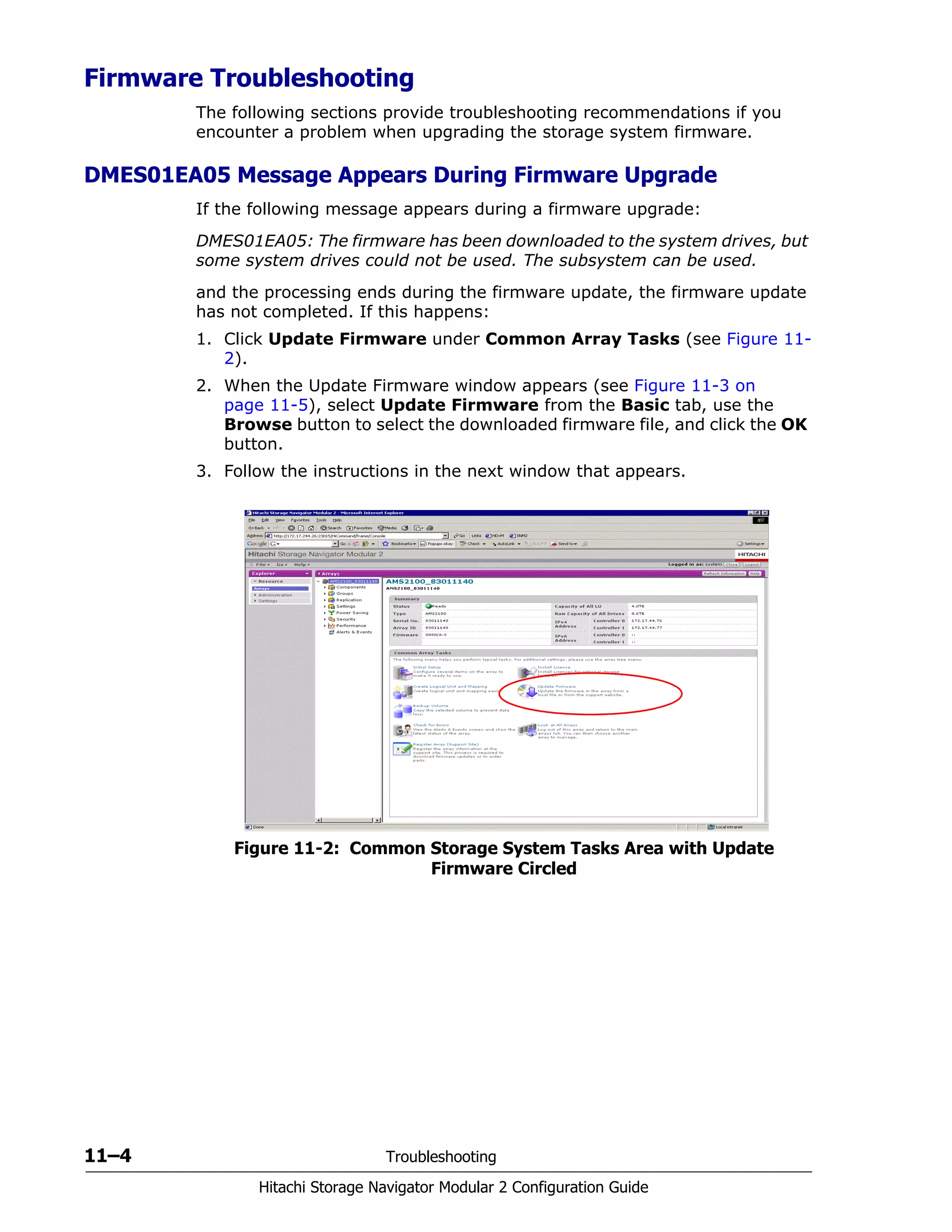
![Troubleshooting 11–3
Hitachi Storage Navigator Modular 2 Configuration Guide
Collecting Trace Information
When you contact Hitachi Technical Support for help with a problem you are
having with the Hitachi AMS 2000 Family storage system, Technical Support
might request that you collect trace and debug information using Navigator
2. To perform this task:
1. Log in to Navigator 2:
http://<IP address of management console PC>:23015/
StorageNavigatorModular/
OR
https://<IP address>:23016/StorageNavigatorModular/
2. Go to the Explorer pane and click Arrays.
3. In the Arrays area, check the status and serial number of the storage
system where the failure occurred (see Figure 5-1 on page 5-3).
4. Click the Collect Trace button at the top-right area of the Failure List
window.
Figure 11-1: Collect Trace Button
NOTE: If entering an IPv6 address in your Web browser, enter the URL in
brackets. Example: http://[xxxx]:23015/StorageNavigatorModular](https://image.slidesharecdn.com/bb72093e-f266-4301-a68b-3cbe334cba97-160202020606/75/MK-99DF8208-03-165-2048.jpg)


![Upgrading Navigator 2 A–3
Hitachi Storage Navigator Modular 2 User’s Guide
4. Create a Certificate Signing Request (CSR) by issuing the following
command line:
For Windows:
For Unix:
The following shows an execution example:
c. Submit the created csr file (httpsd.csr, in the above example) to
the CA (Certificate Authority) and obtain the signed certificate.
Even if you do not submit the csr file or obtain the signed certificate
file from the CA, you can correspond to SSL by creating the
certificate file with your signature using the hcmdssslc (sslc for
Unix) command. In this case, however, the warning window appears
at the time of the initial window display of Navigator 2, and when the
applet launches.
To create a self-signed certificate file, include the hcmdssslc
command (sslc command for Unix) in the following command line:
hcmdssslc req -config C:Program FilesHiCommandBasehttpsd
sslcbindemoCAsslc.cnf
-new -key c:cahttpsdkey.pem -out c:cahttpsd.csr
/sslc req -config /opt/HiCommand/Base/httpsd/sslc/bin/demoCA/sslc.cnf
-new -key ca/httpsdkey.pem -out /ca/httpsd.csr
Using configuration from C:Program
FilesHiCommandBasehttpsdsslcbindemoCA
sslc.cnf
You will be prompted to enter information to incorporate
into the certificate request.
This information is called a Distinguished Name or a DN.
There are many fields however some can remain blank.
Some fields have default values.
Enter '.', to leave the field blank.
-----
Country Name (2 letter code) []:us
State or Province Name (full name) []:California
Locality Name (eg, city) []:San Jose
Organization Name (eg, company) []:Hitachi
Organizational Unit Name (eg, section) []:Hitachi
Common Name (eg, YOUR name) []:Hitachi
Email Address []:
Please enter the following 'extra' attributes
to be sent with your certificate request
A challenge password []:
An optional company name []:](https://image.slidesharecdn.com/bb72093e-f266-4301-a68b-3cbe334cba97-160202020606/75/MK-99DF8208-03-173-2048.jpg)
![A–4 Upgrading Navigator 2
Hitachi Storage Navigator Modular 2 User’s Guide
For Windows:
For Unix:
5. Using a text editor, open the httpsd.conf file in <installation
directory>Basehttpsdconf and edit it as follows:
a. Remove # from the following underlined lines, which are commented
out by default, and change the values of SSLCertificateFile and
SSLCertificateKeyFile.
b. Specify the signed certificate file obtained from the CA for
SSLCertificateFile and the full path of the private key file created
in step 3 for SSLCertificateKeyFile.
The contents of the file are shown below:
6. Start the Navigator 2 service and then start the service for the Hitachi
Storage Command Suite Common Components (see Stopping Hitachi
Storage Command Suite common components on page 10-17).
For instances where Navigator 2 shows the storage system has a warning
status, see Upgrading Firmware When the Storage System Has a Warning
Status on page 11-5.
hcmdssslc x509 -in c:cahttpsd.csr -out c:canewcert.pem -reg -signkey
c:cahttpsdkey.pem -days 365
c:cahttpsd.csr: CSR to CA
c:canewcert.pem: self-signed certificate
c:cahttpsdkey.pem: key file
./sslc x509 -in /ca/httpsd.csr -out /ca/newcert.pem -reg -signkey
/ca/httpsdkey.pem -days 365
SSLSessionCacheSize 0
#Listen 23016
#Listen [::]:23016
#<VirtualHost s1j-orca2xp:23016>
# ServerName s1j-orca2xp
# SSLEnable
# SSLProtocol SSLv3 TLSv1
# SSLRequireSSL
# SSLCertificateFile "C:/ca/httpsd.pem"
# SSLCertificateKeyFile "C:/ca/httpsdkey.pem"
# SSLCACertificateFile "C:/Program #Files/HiCommand/Base/httpsd/conf/
ssl/cacert/anycert.pem"
# SSLSessionCacheTimeout 3600
#</VirtualHost>](https://image.slidesharecdn.com/bb72093e-f266-4301-a68b-3cbe334cba97-160202020606/75/MK-99DF8208-03-174-2048.jpg)

![A–8 Upgrading Navigator 2
Hitachi Storage Navigator Modular 2 User’s Guide
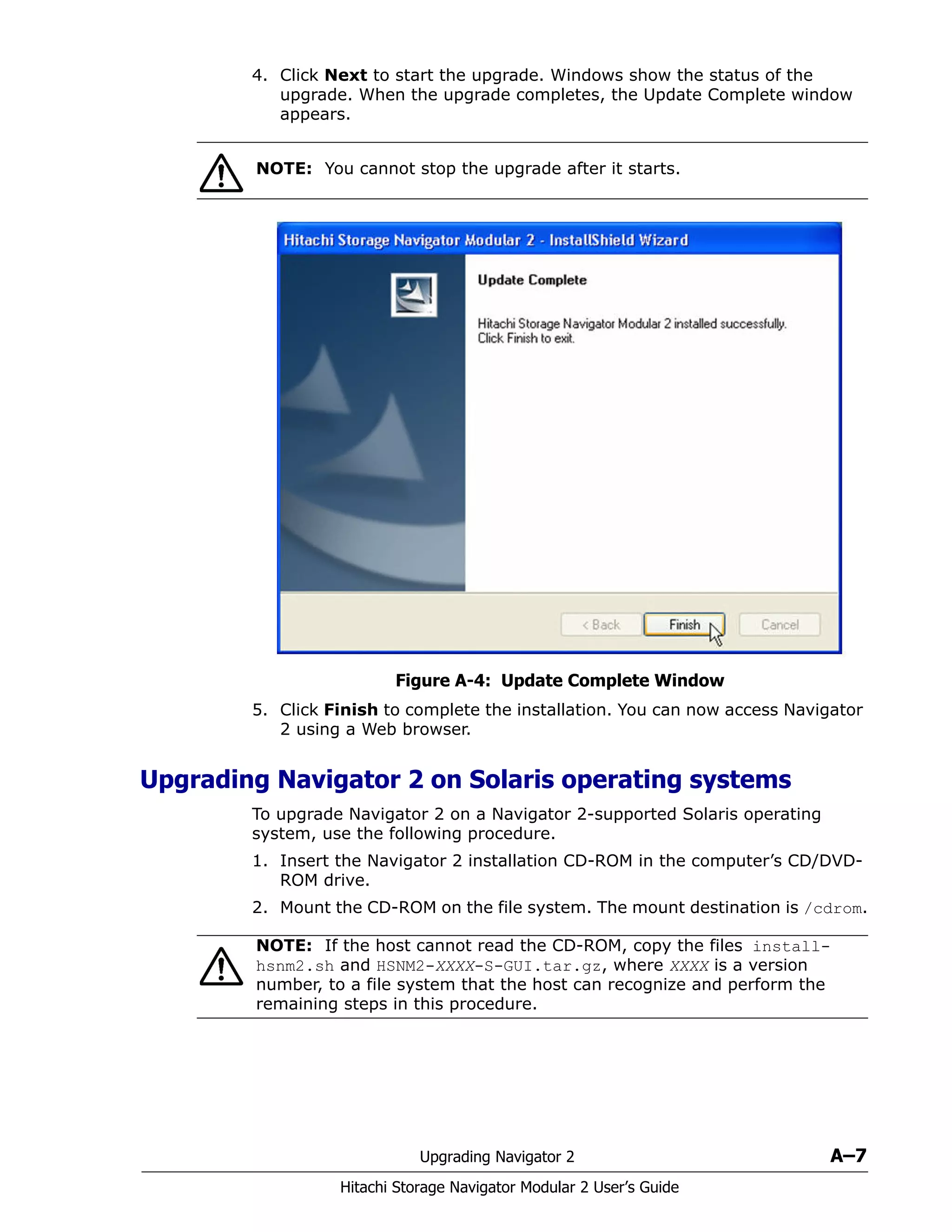
3. Create the temporary directory called/temporary that has more than
600 MB of available disk space on the file system and expand the
compressed files. In the example below, XXXX denotes a version number.
4. In the console, issue the following command.
Specify the IP address (or host name) and port number used to access
Navigator 2. If you use 1099 for the port number, you can omit the -p
option. Do not specify 127.0.0.1 and localhost. Otherwise, the Navigator
2 Applet window is not displayed. In DHCP environments, specify host
name (computer name) in the [IP address] field.
5. Delete the temporary directory
Upgrading Navigator 2 on Linux operating systems
To upgrade Navigator 2 on a Navigator 2-supported Linux operating system,
use the following procedure.
1. If the host is running applications other than Navigator 2 that use Hitachi
Storage Command Suite Common Components on the host, stop the
daemon process of the Hitachi Storage Command Suite Common
Components.
2. Insert the Navigator 2 installation CD-ROM in the computer’s CD/DVD-
ROM drive.
3. Mount the CD-ROM on the file system. The mount destination is /cdrom.
4. In the console, issue the following command:
Do not specify 127.0.0.1 and localhost. Otherwise, the Navigator 2
Applet window will not appear. In DHCP environments, specify the host
name (computer name) to the IP Addr. field.
mkdir /temporary
cd /temporary
gunzip < /cdrom/HSNM2-XXXX-S-GUI.tar.gz | tar xf -
/temporary/install-hsnm2.sh -a [IP address] -p [port number]
NOTE: If the host cannot read the CD-ROM, copy the files install-
hsnm2.sh and HSNM2-XXXX-L-GUI.rpm, where XXXX is a version number, to
a file system that the host can recognize and perform the remaining steps
in this procedure.
sh /cdrom/install-hsnm2.sh](https://image.slidesharecdn.com/bb72093e-f266-4301-a68b-3cbe334cba97-160202020606/75/MK-99DF8208-03-178-2048.jpg)