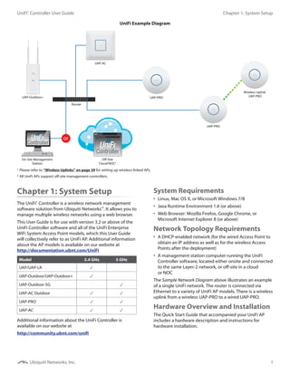
This document is the user guide for version 3.2 of the UniFi Controller software. It provides instructions on setting up an enterprise WiFi system using Ubiquiti Networks' UniFi access points and the UniFi Controller management software. The guide covers system requirements, network topology, hardware installation, software installation and use of the UniFi Controller interface. It provides details on configuring and monitoring the access points, users and guests as well as other features like maps, statistics and insights.
![6
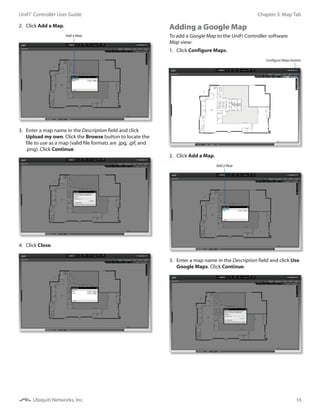
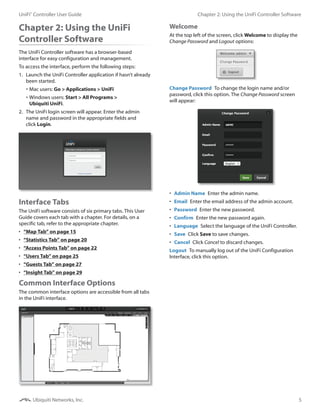
Chapter 2: Using the UniFi Controller SoftwareUniFi®
Controller User Guide
Ubiquiti Networks, Inc.
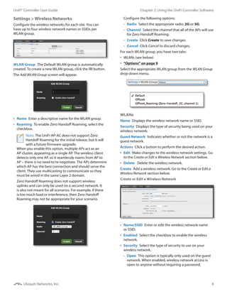
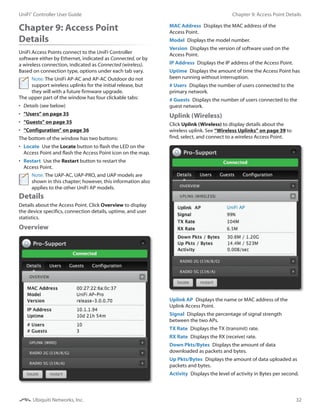
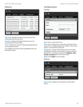
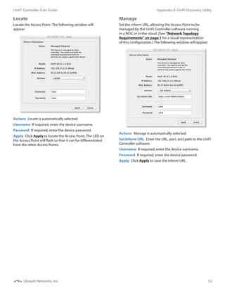
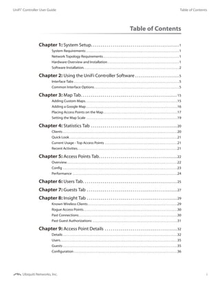
Site
The UniFi Controller can manage multiple UniFi networks,
which are called sites. Each site has its own configurations,
maps, statistics, guest portals, and site administrator
accounts. The multiple sites are logically separated, and
the initial site is named default.
Site To create a new site, click the arrow to display the
drop-down menu.
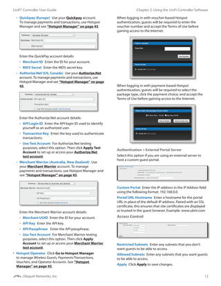
Click Add Site, and the Add Site screen will appear:
• ID Enter a unique name to permanently identify the
site. It will be used in the URL, and if you customize the
portal, it will be used to identify the site folder.
• Name Enter a name that describes the site. It will be
used in the Site drop-down menu.
• Save Click Save to save changes.
• Cancel Click Cancel to discard changes.
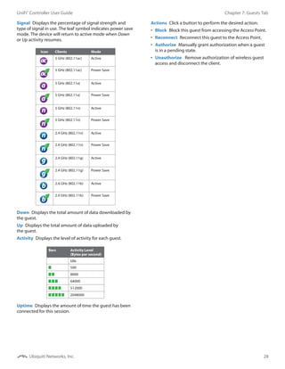
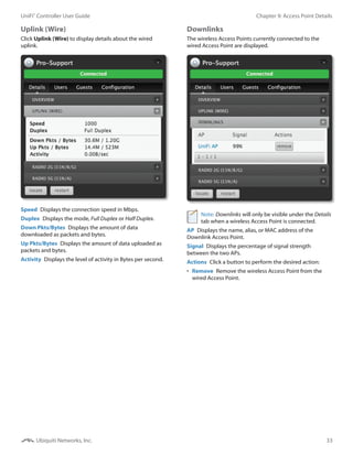
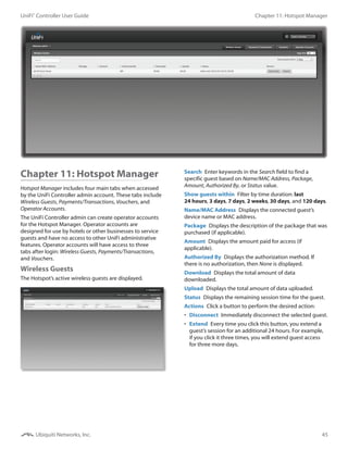
APs
• active Click the arrow to display a list of Access
Points that are online.
• inactive Click the arrow to display a list of Access
Points that were previously online but are no longer
accessible.
• pending Click the arrow to display a list of Access
Points that are not yet managed but are available.
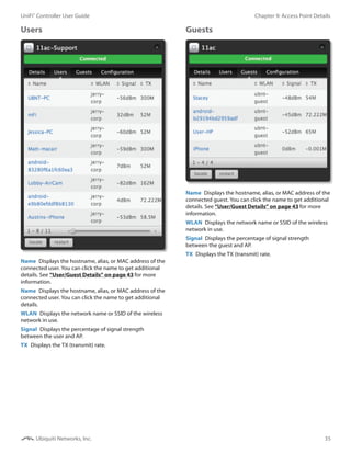
Stations
• users Displays the total number of users.
• guests Displays the total number of guests.
Refresh
Click the Refresh icon to update the on-screen
information. Select the refresh interval: Manually, Every
5 seconds, Every 15 seconds, Every 30 seconds, Every
minute, Every 2 minutes (default), or Every 5 minutes.
At the bottom of the screen, there are four tabs:
• Recent Events (see the next column)
• Alerts (see the next column)
• “Settings” on page 7
• “Admin” on page 14
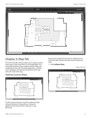
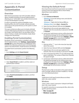
Recent Events
The Recent Events tab displays a list of recent events, along
with the corresponding date, time, and message.
Event Slider Move the slider right and left to navigate
between pages of events.
Search You can enter text that you want to search for.
Simply begin typing; there is no need to press Enter.
You can apply one of the following filters:
• Admin Only display recent events for the administrator.
• AP Only display recent events for the AP.
• All Display all of the recent events.
within Filter recent events based on the time period you
specify. Select 1 hour, 8 hours, 24 hours, 2 days, 7 days,
2 weeks, or 1 month.
Clicking an Event Device Link
The messages have clickable links [blue text in gray
brackets] for AP (see “Access Point Details” on page
32), User, and Guest (see “User/Guest Details” on page
43). Details vary based on the selection.
Alerts
When there is an alert, a red circle will flash on the Alerts
tab. The Alerts tab displays a list of important events, along
with the corresponding date, time, and message.
Alert Slider Move the slider right and left to navigate
between pages of alerts.
Search You can enter text that you want to search for.
Simply begin typing; there is no need to press Enter.
You can apply one of the following filters:
• Unarchived Only display alert messages that have not
been archived.
• All Display all of the alert messages.
Archive All Archive all of the alert messages.
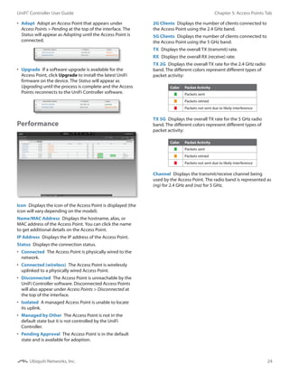
Adopt Adopt an Access Point that is waiting for adoption.
Archive Archive the selected alert message.](https://image.slidesharecdn.com/unificontrollerug-150804081443-lva1-app6891/85/Uni-fi-controller_ug-9-320.jpg)
![7
Chapter 2: Using the UniFi Controller SoftwareUniFi®
Controller User Guide
Ubiquiti Networks, Inc.
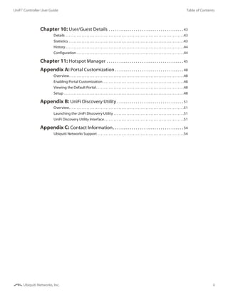
Clicking an Alert Device Link
The messages have clickable links [blue text in gray
brackets] for AP (see “Access Point Details” on page
32), User, and Guest (see “User/Guest Details” on page
43). Details vary based on the selection.
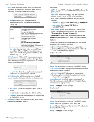
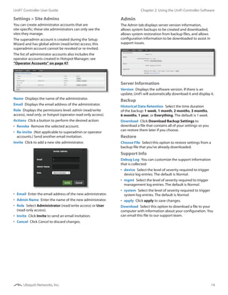
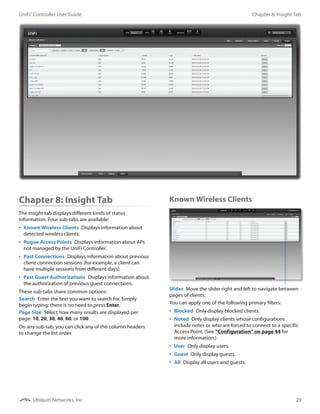
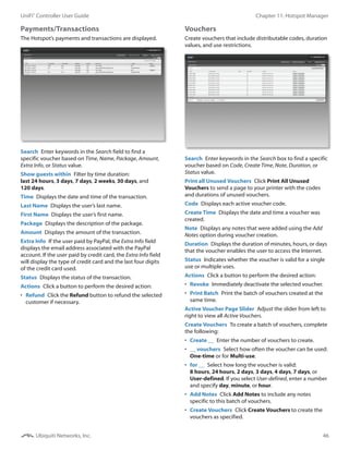
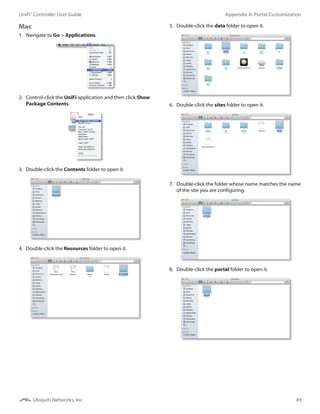
Settings
The Settings tab displays a list of available sub-tabs:
Site Site-related settings.
Wireless Networks Wireless networks and
group setup, including Zero Handoff Roaming.
Guest Control Guest portal and policies.
User Groups User group settings.
Controller Identity, discovery, and email server
settings.
>_ Site Admins Admin accounts and privileges.
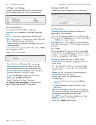
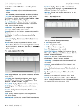
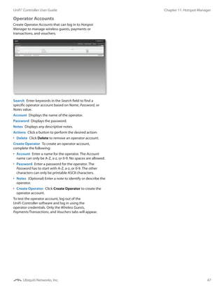
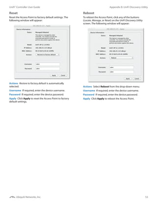
Settings > Site
Configure the site-specific settings. To switch sites, select a
different site from the Site drop-down menu at the top of
any screen.
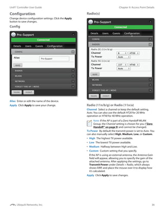
Site Configurations
Site Name Change the name of the site.
Country Select your country from the drop-down menu.
Automatic Upgrade When enabled, this option will
automatically upgrade your firmware when an update is
available.
LED When enabled, the LED on the Access Point will light
up. When disabled, the LED will turn off.
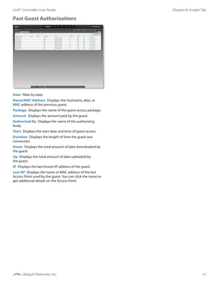
Uplink Connectivity Monitor It monitors the uplinks of
the managed Access Points, either wired or wireless, by
checking to see if the gateway/custom IP can be reached.
The monitor and wireless uplink capability are enabled by
default.
• Use default gateway Enabled by default. All managed
Access Points will use the gateway of the Access Point
that is providing IP information, either by DHCP or Static
designation.
• Use custom IP Select Use custom IP to specify an
IP address; all managed Access Points will use the IP
address you enter in the Uplink IP address field.
SNMP Select this option to activate the SNMP
(Simple Network Monitor Protocol) agent. SNMP
is an application layer protocol that facilitates the
exchange of management information between
network devices. Network administrators use SNMP
to monitor network‑attached devices for issues that
warrant attention.
• Community String Specify the SNMP community
string. It is required to authenticate access to MIB
(Management Information Base) objects and functions
as an embedded password. The device supports a
read-only community string; authorized management
stations have read access to all the objects in the MIB
except the community strings, but do not have write
access. The device supports SNMP v1. The default
is public.
Remote Logging Enable to define a remote syslog server.
Enter the IP address and port of the syslog server.
Device Password The Device Password protects SSH
access to the UniFi APs. It is randomly generated when you
create a site. All devices in the same site share the same
SSH username and password. You can also make changes:
• Username Enter the new username.
• Password Enter the new password.
Apply Click Apply to save changes.](https://image.slidesharecdn.com/unificontrollerug-150804081443-lva1-app6891/85/Uni-fi-controller_ug-10-320.jpg)