Downloaded 23 times


![Getting Started 3-19
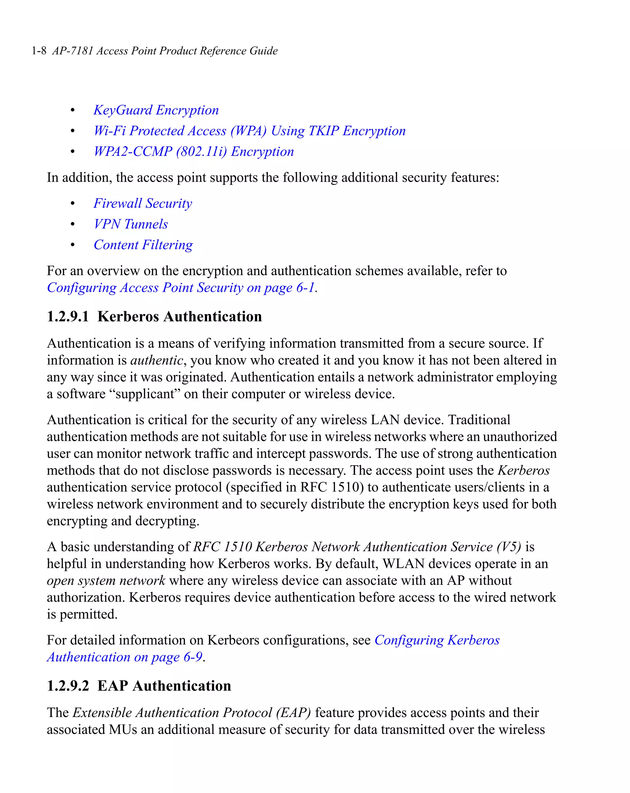
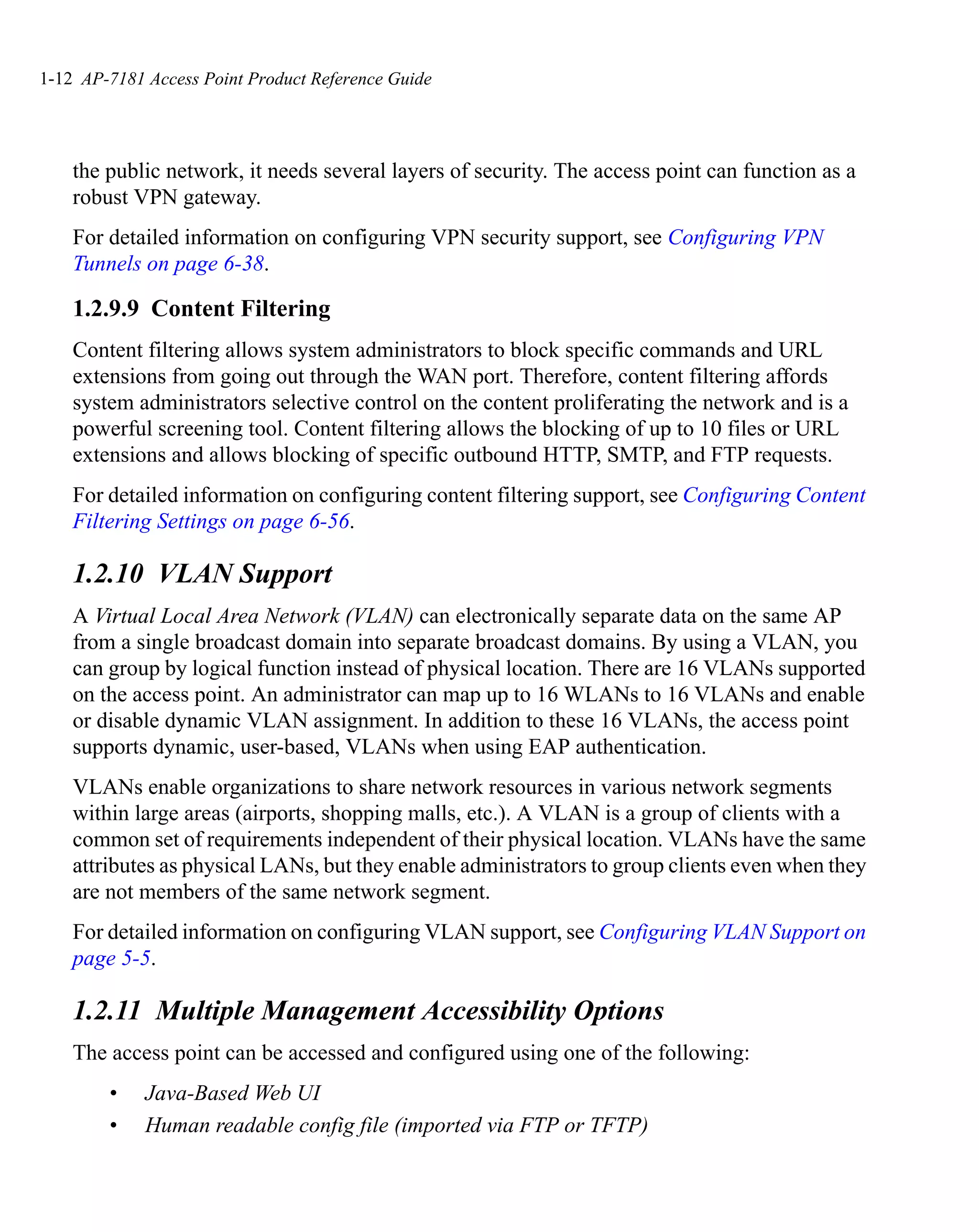
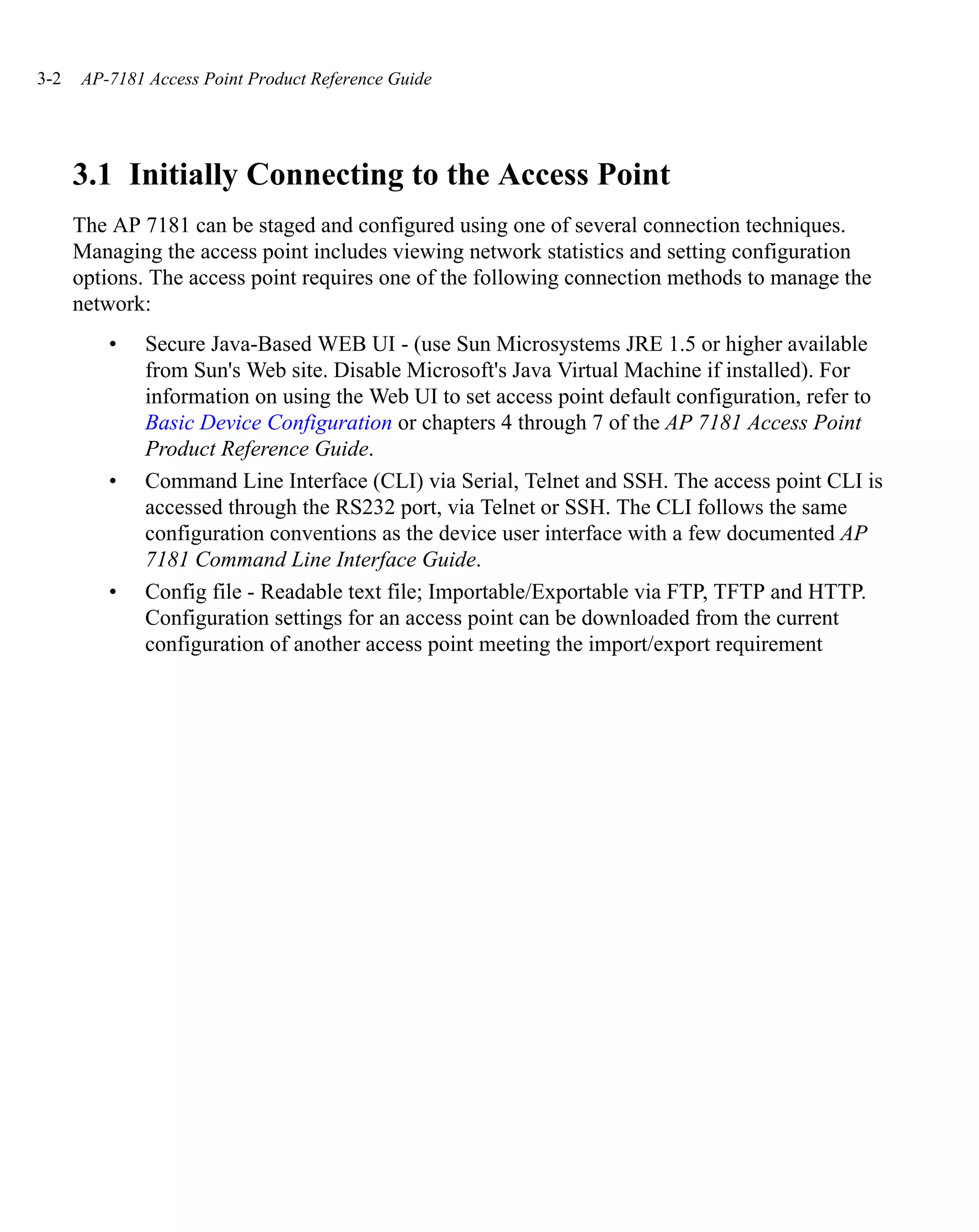
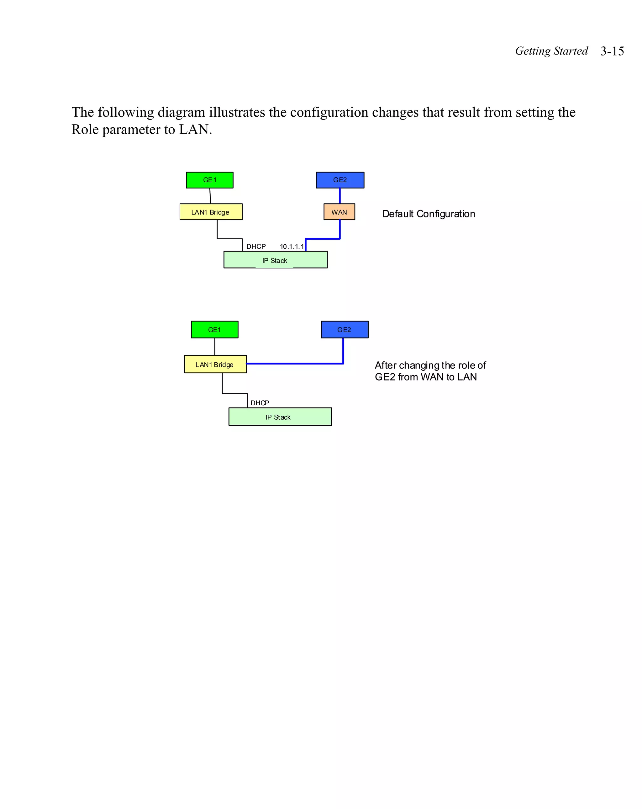
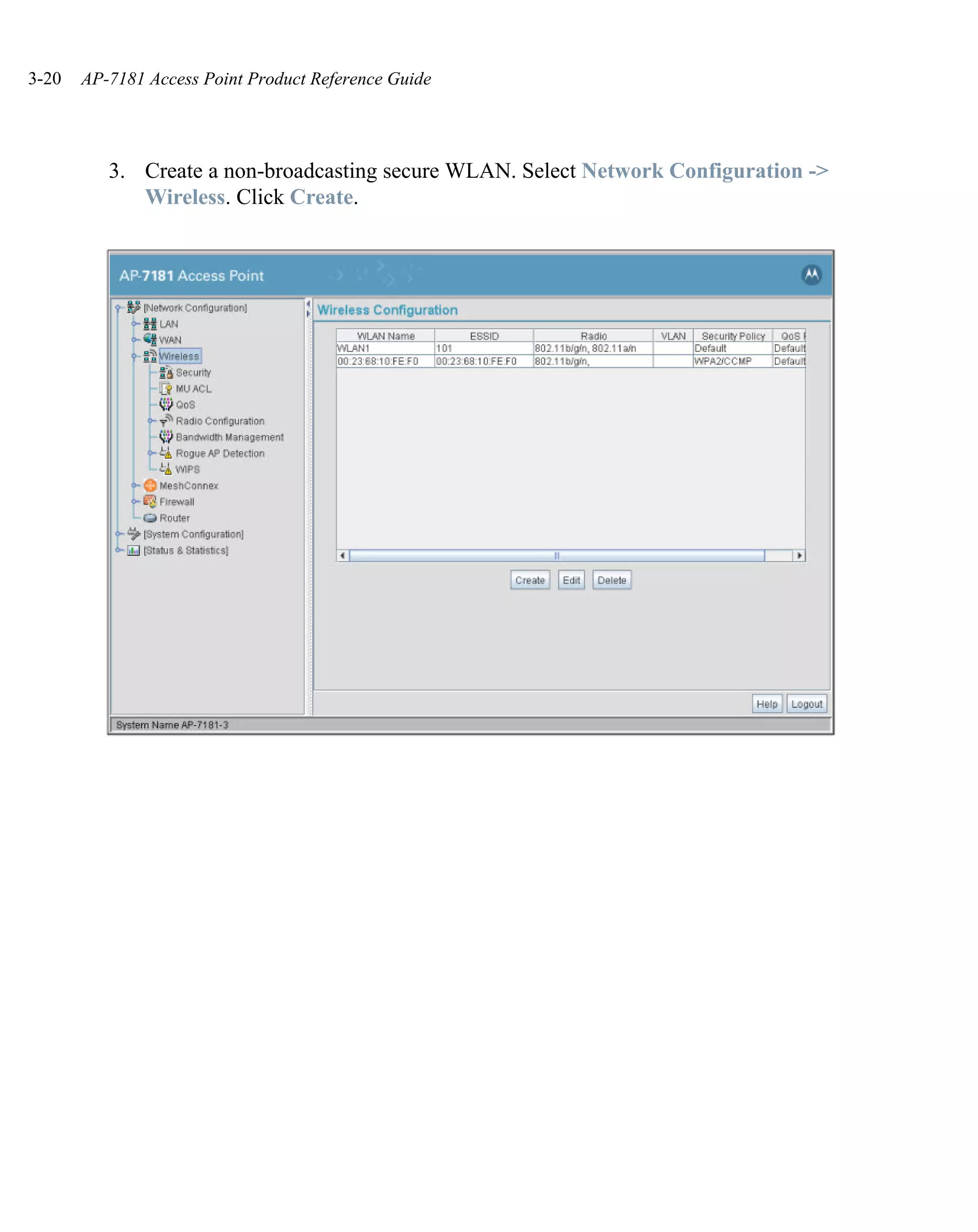
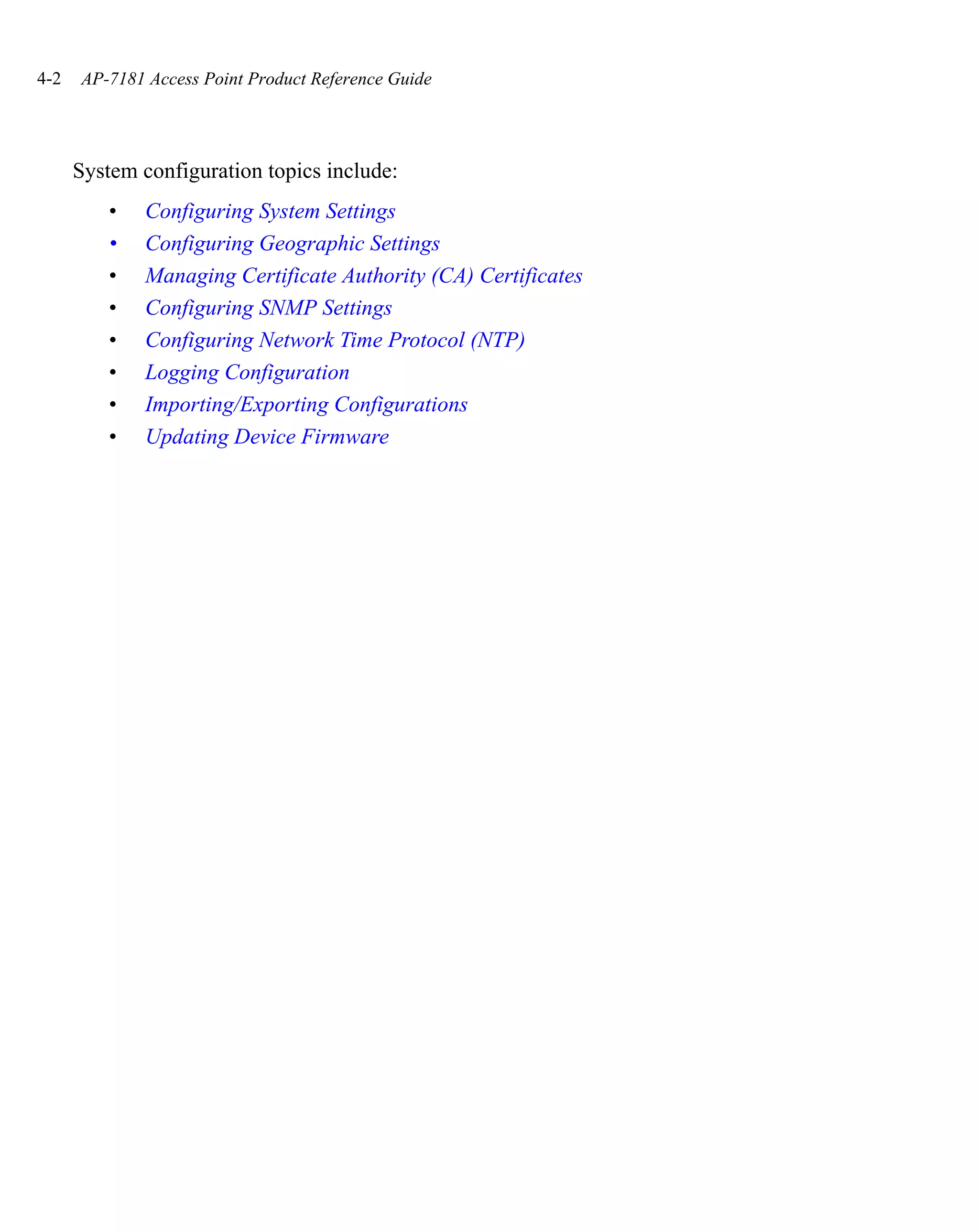
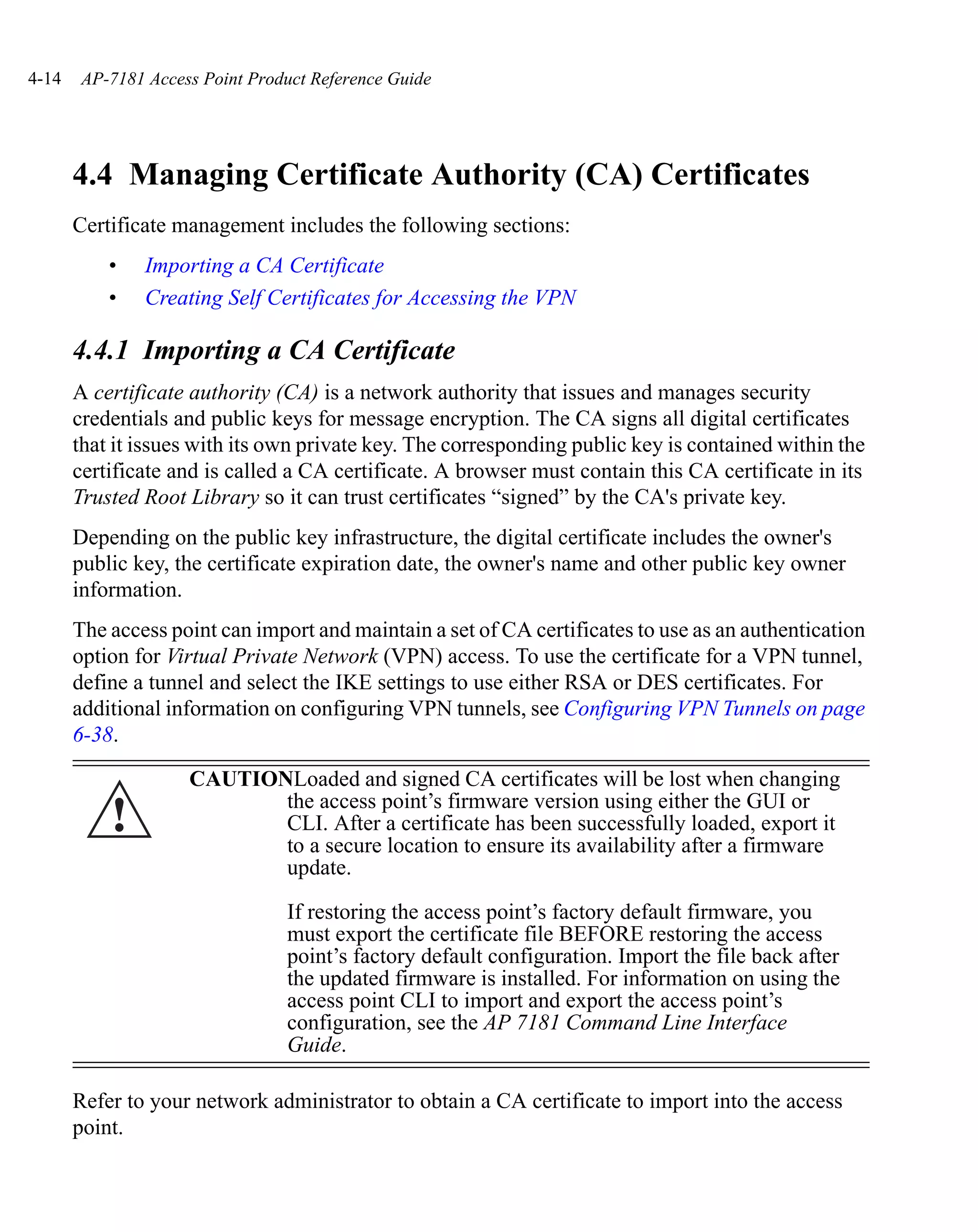
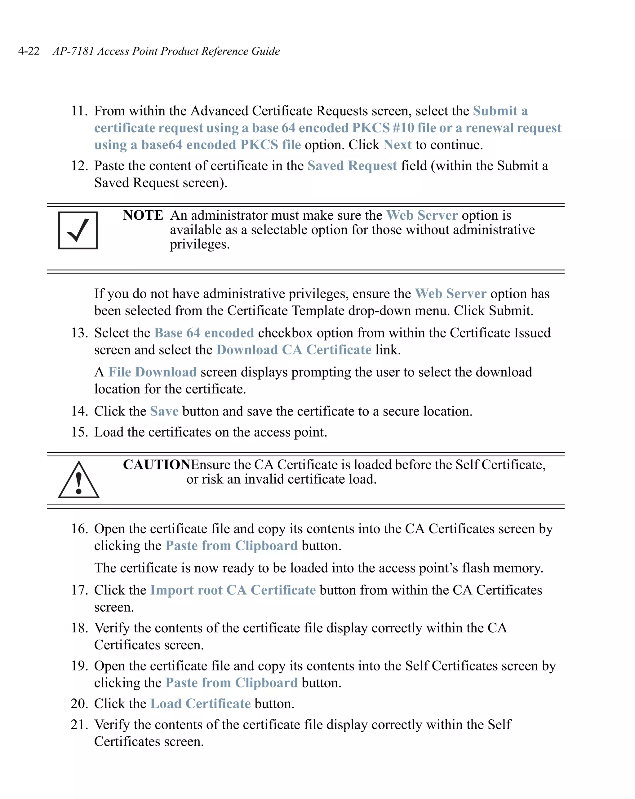
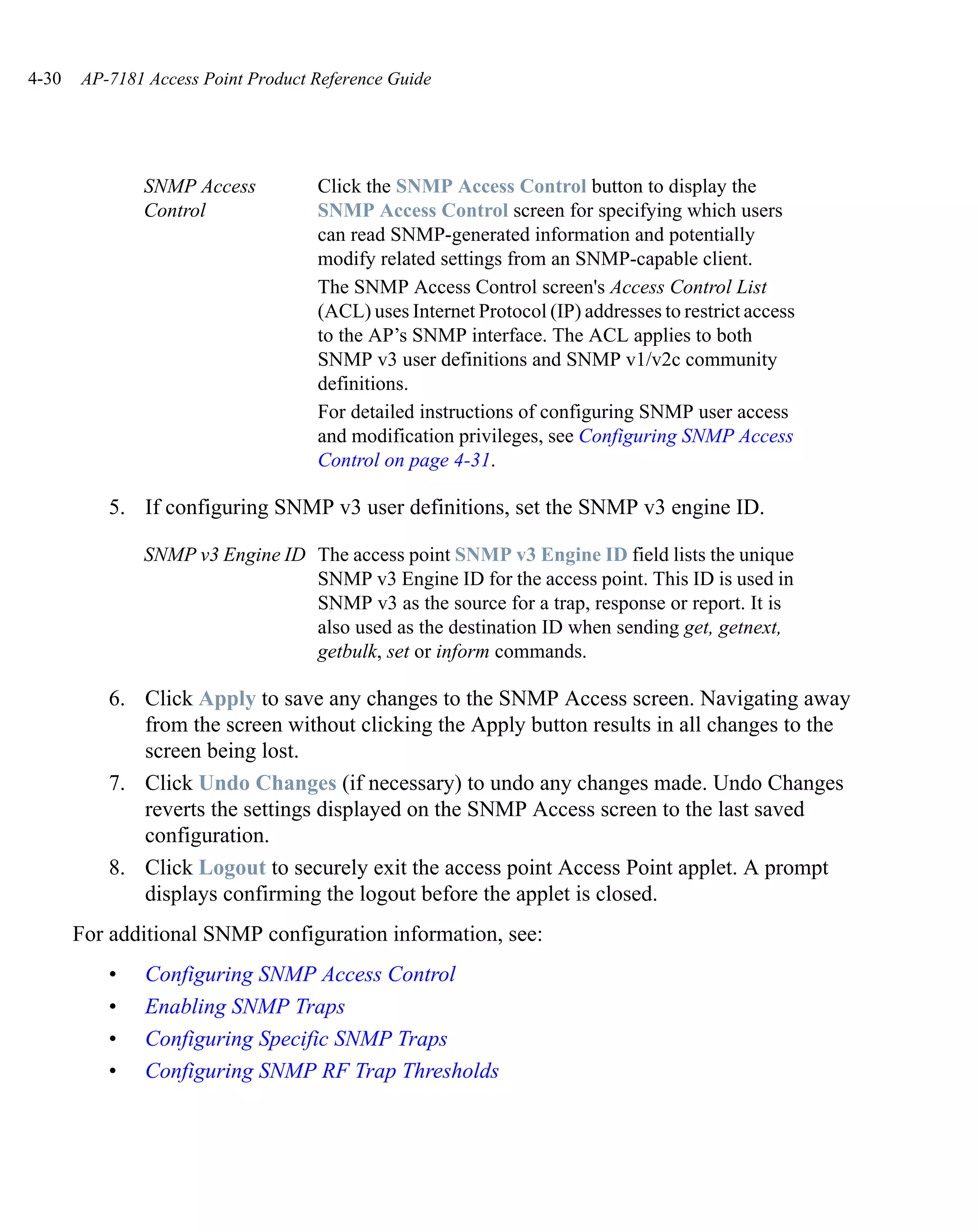
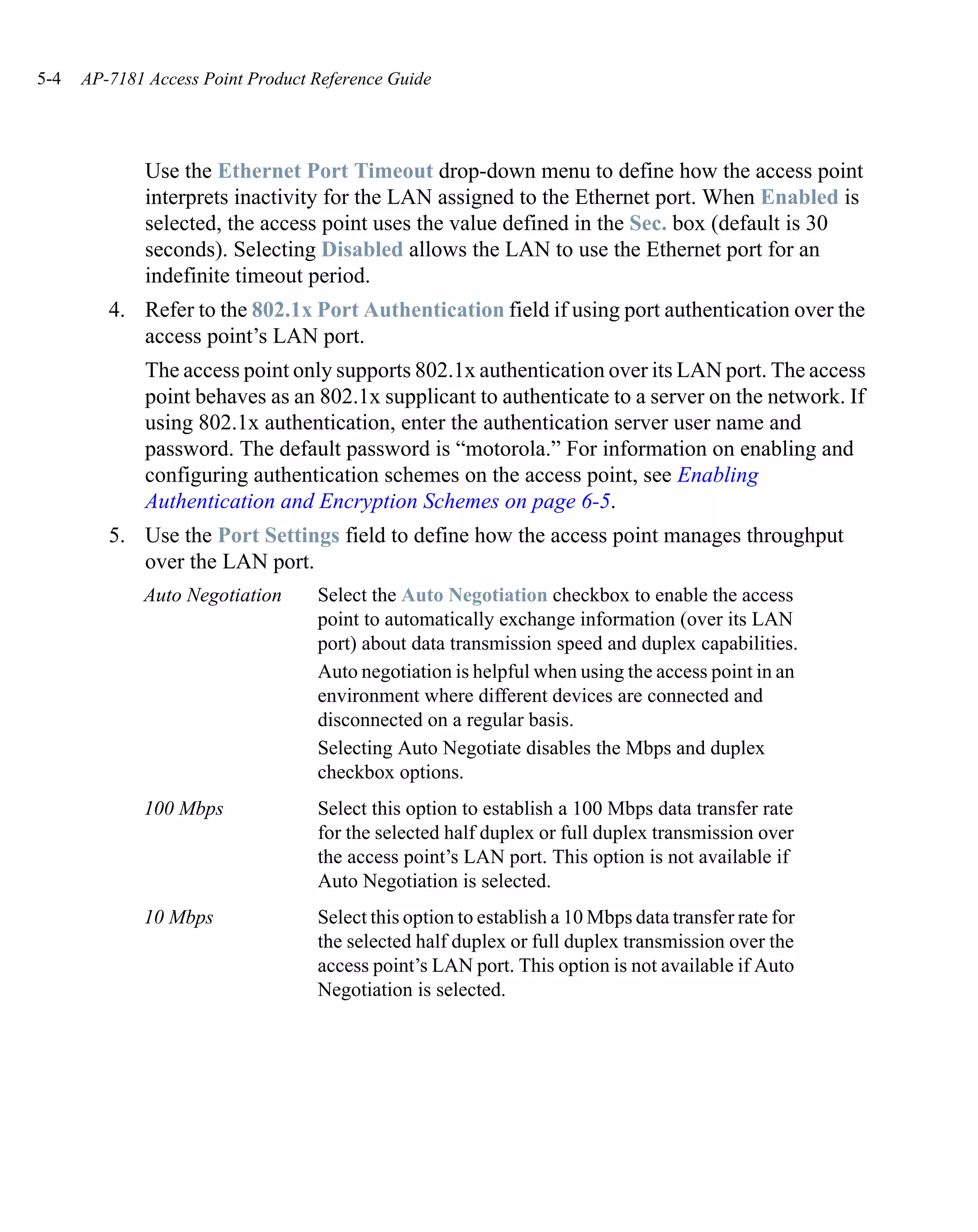
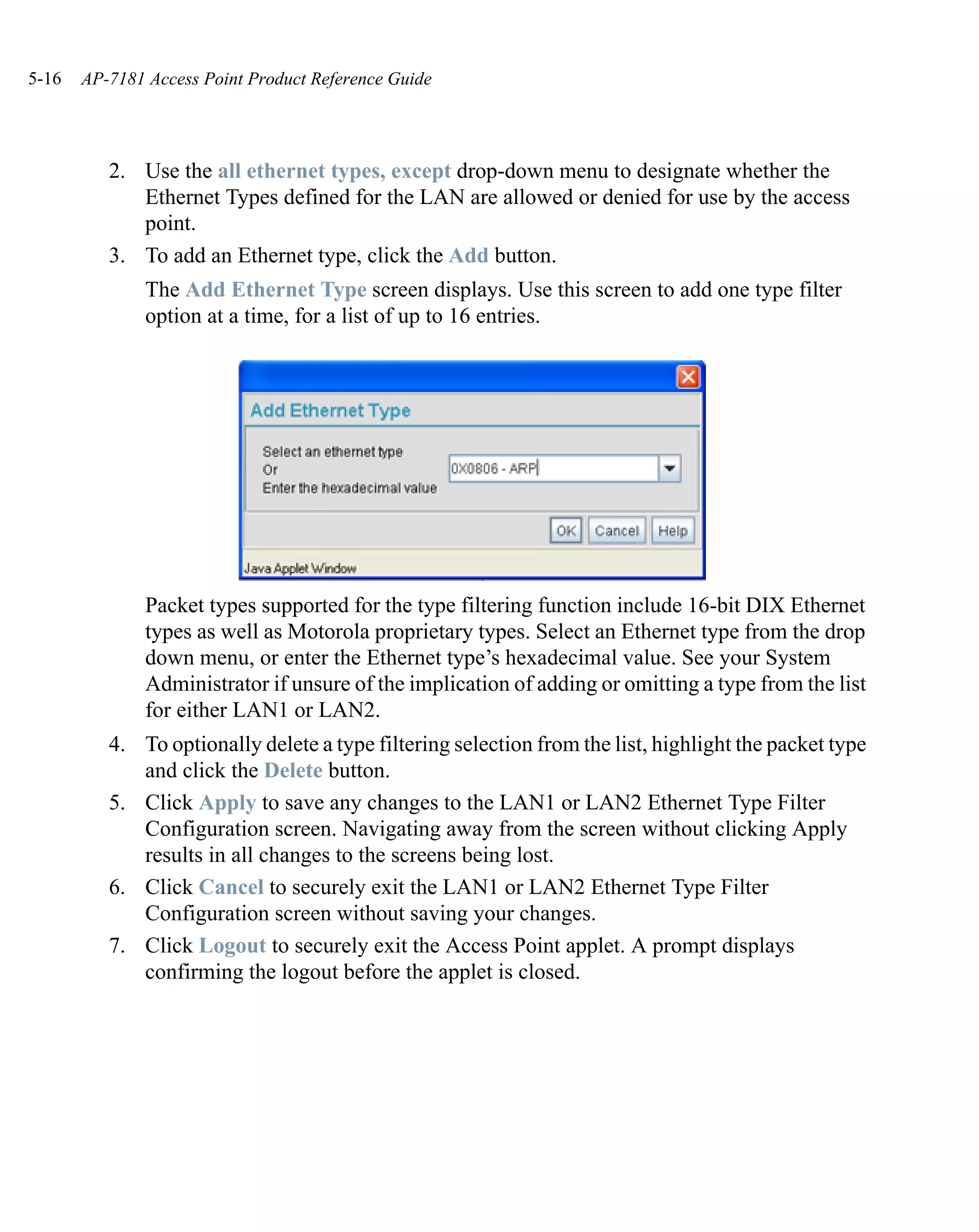
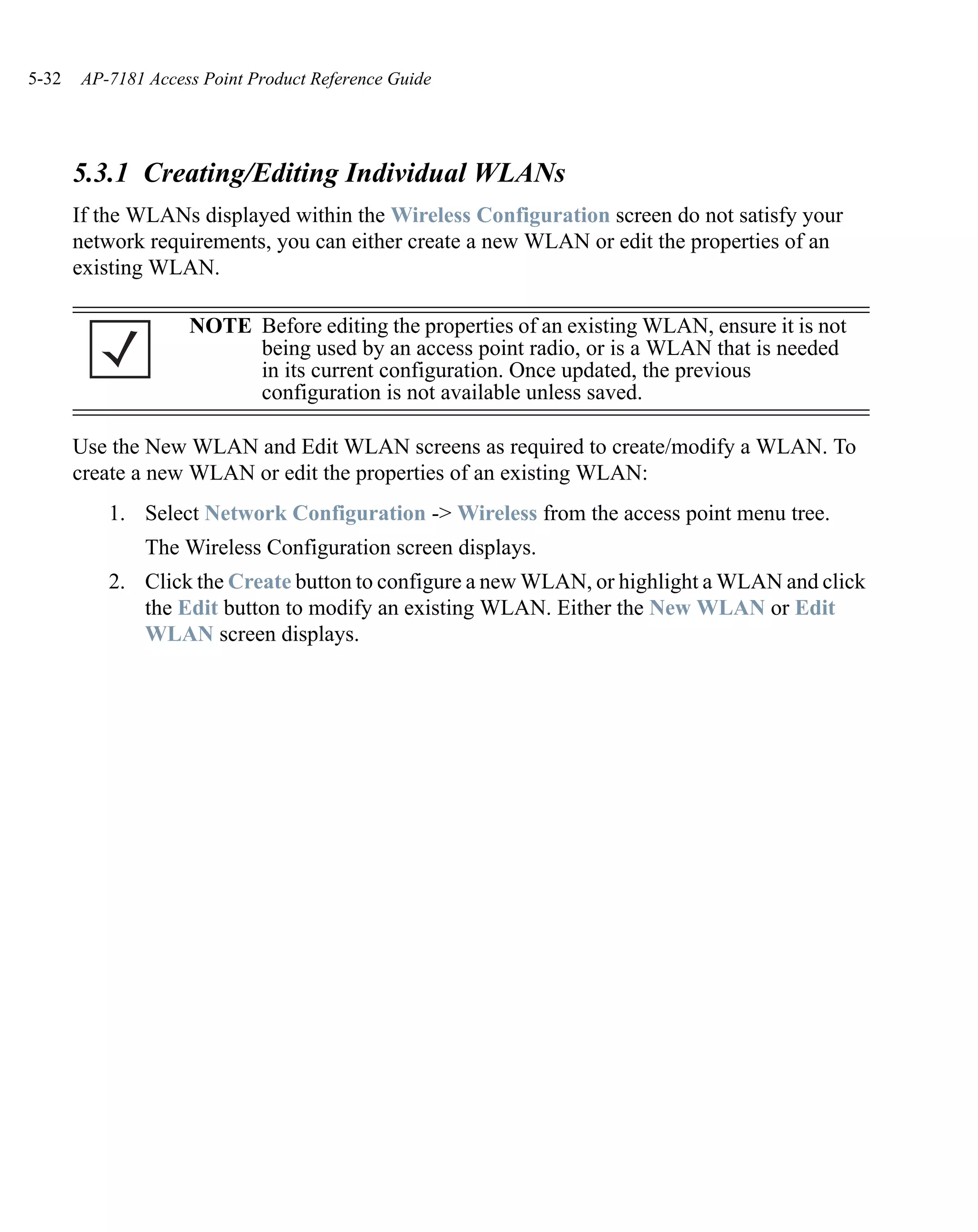
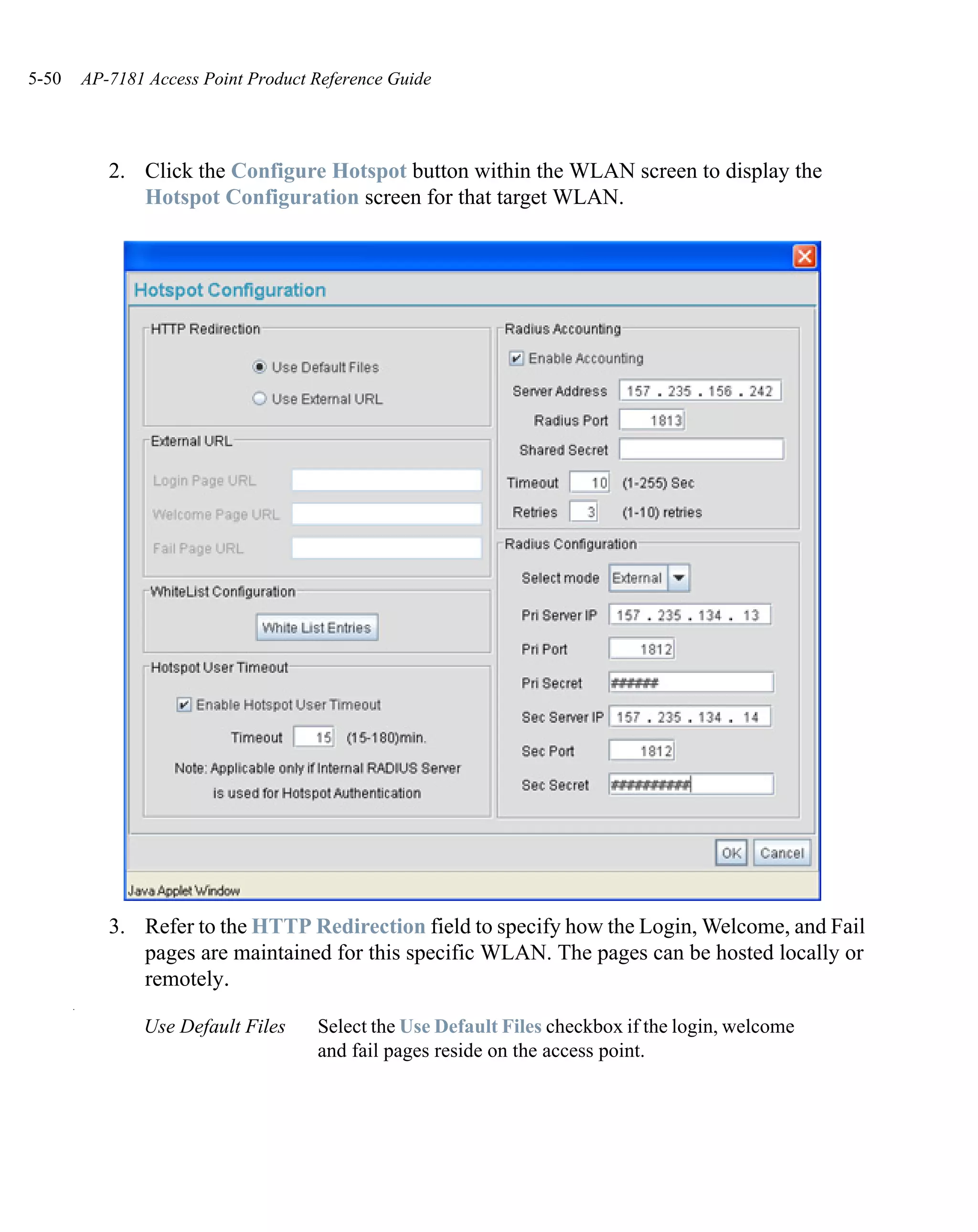
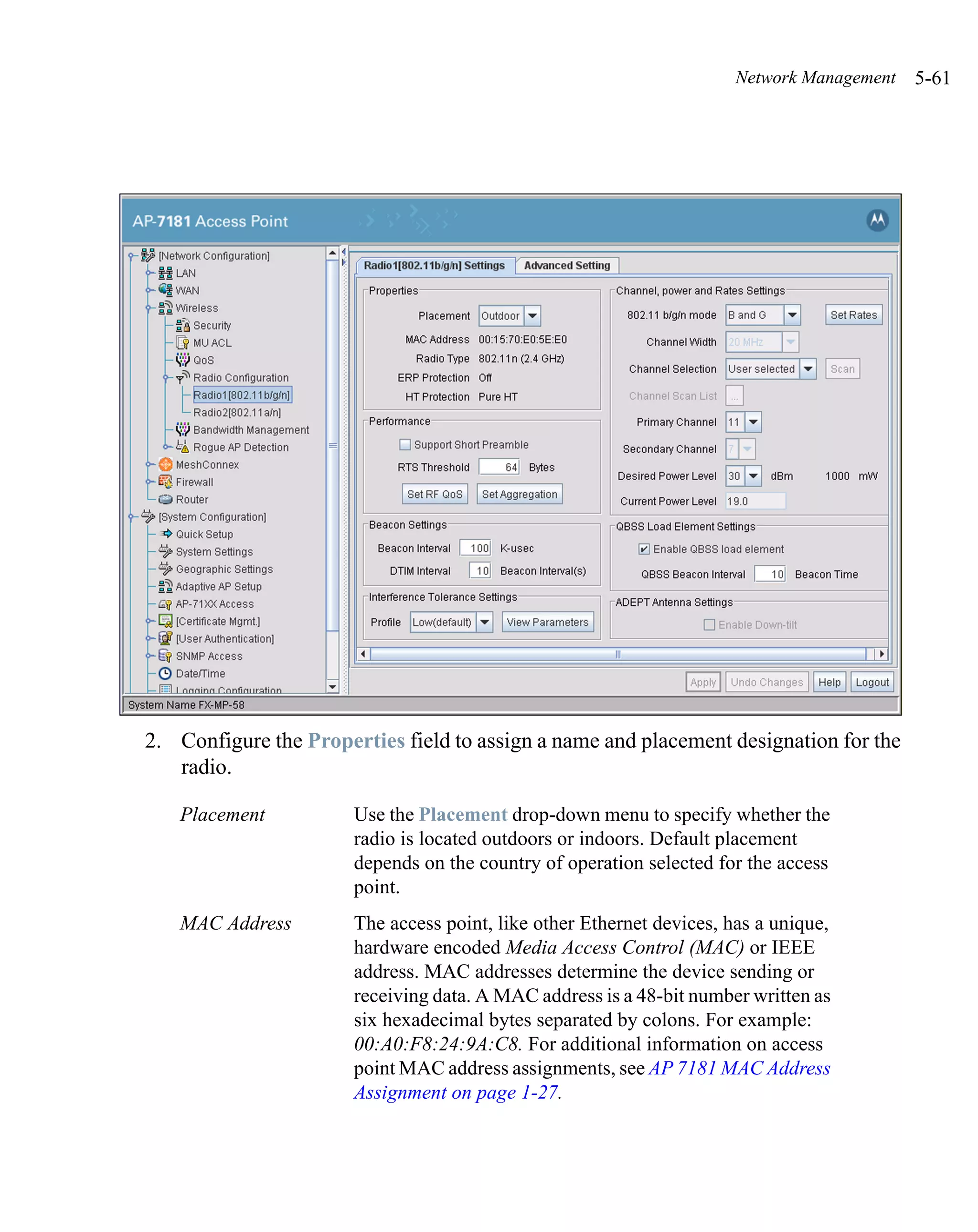
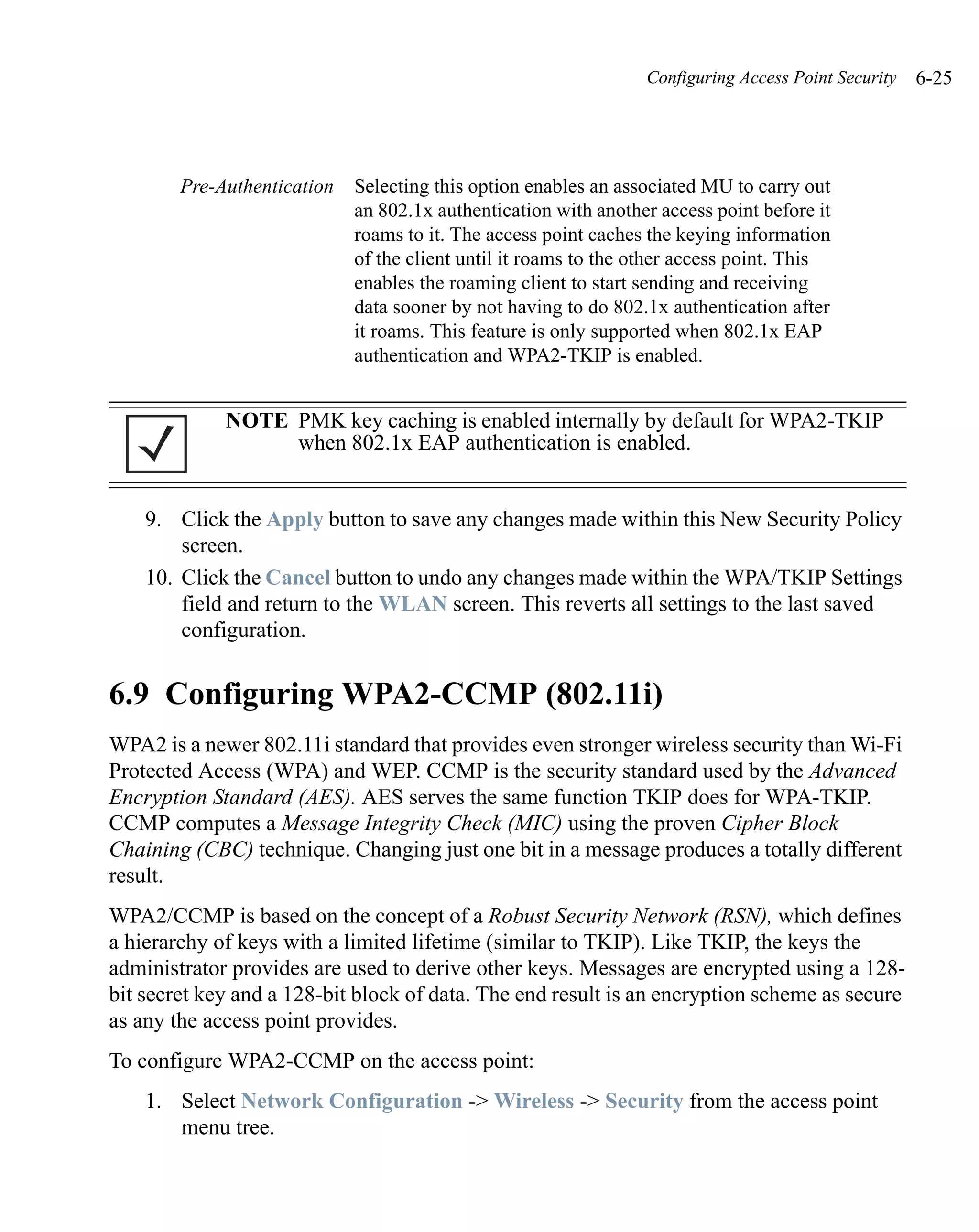
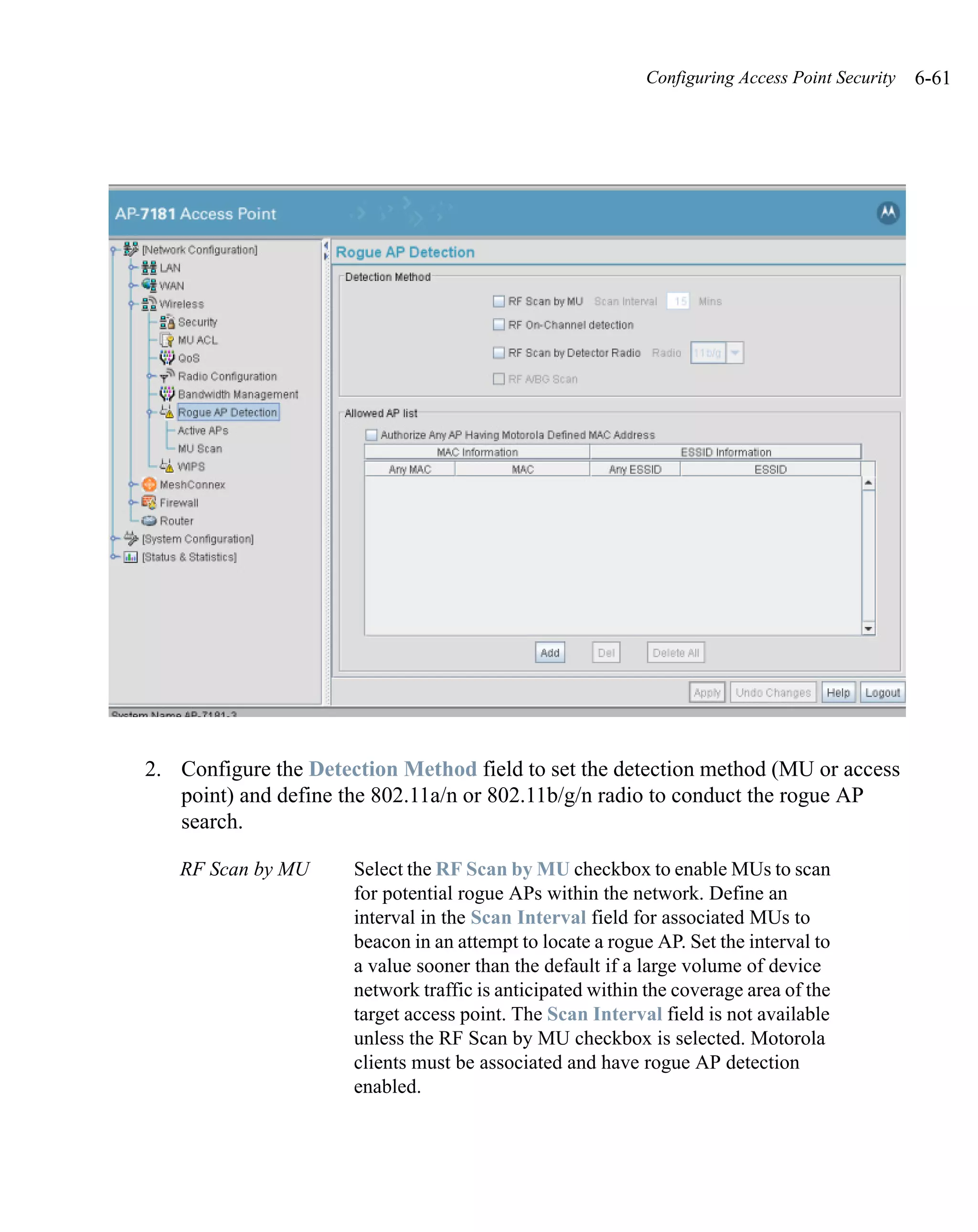
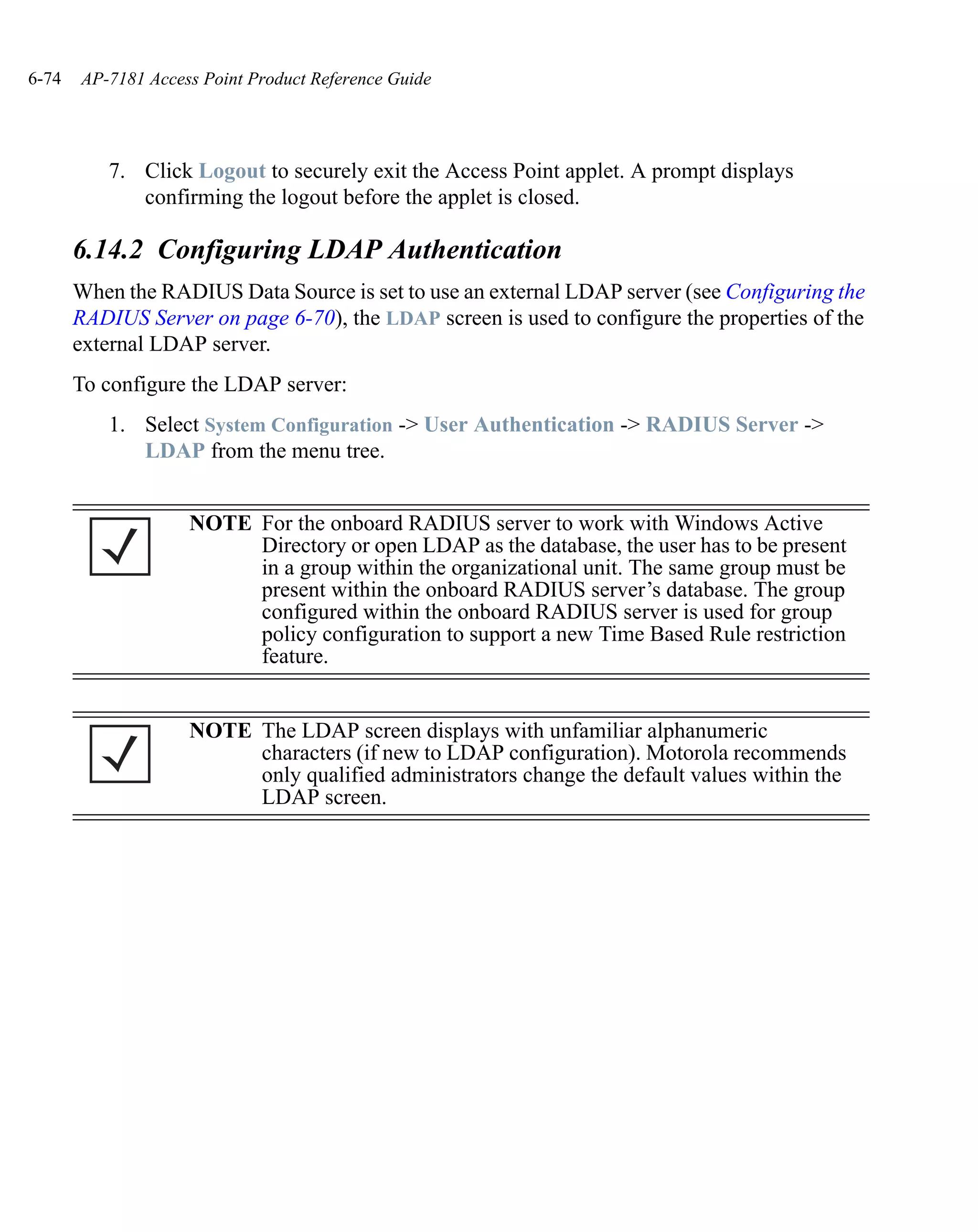
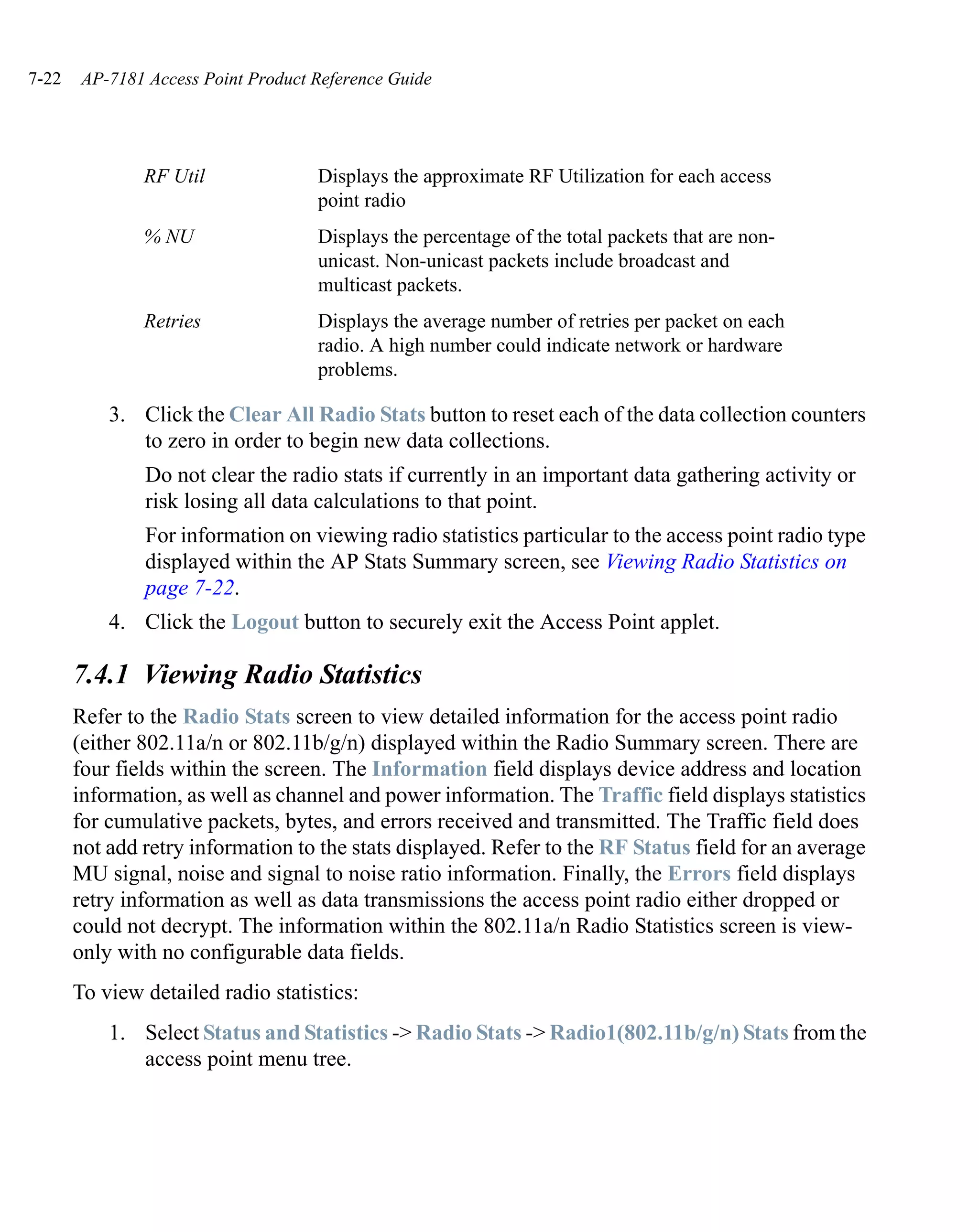
2. Determine what ESSID (or network name) to use. It is recommended that a unique
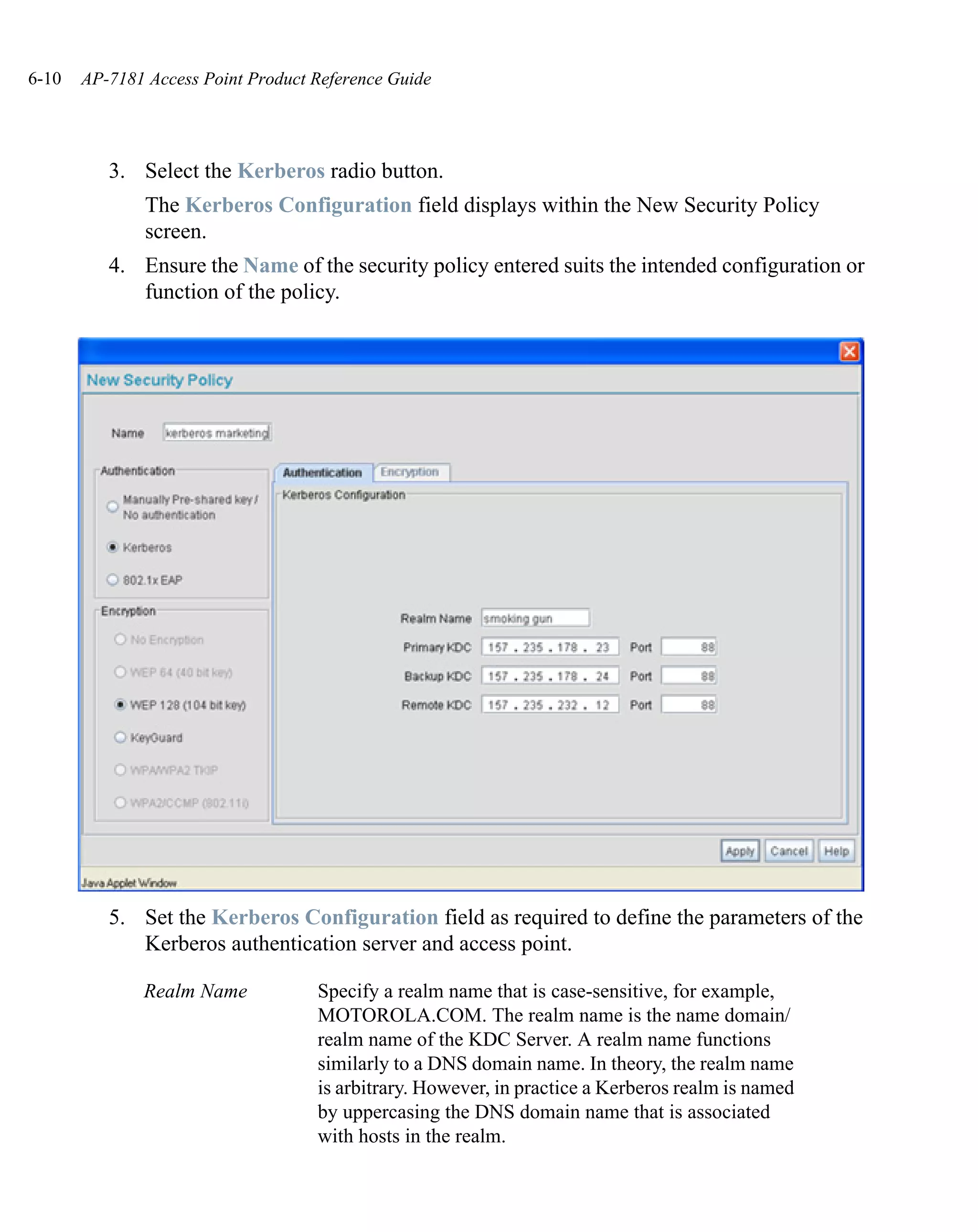
ESSID be used for each AP 7181. Since the recovery WLAN is going to be on the
2.4 GHz radio, we chose to use the MAC address of the 2.4 GHz radio. This can be
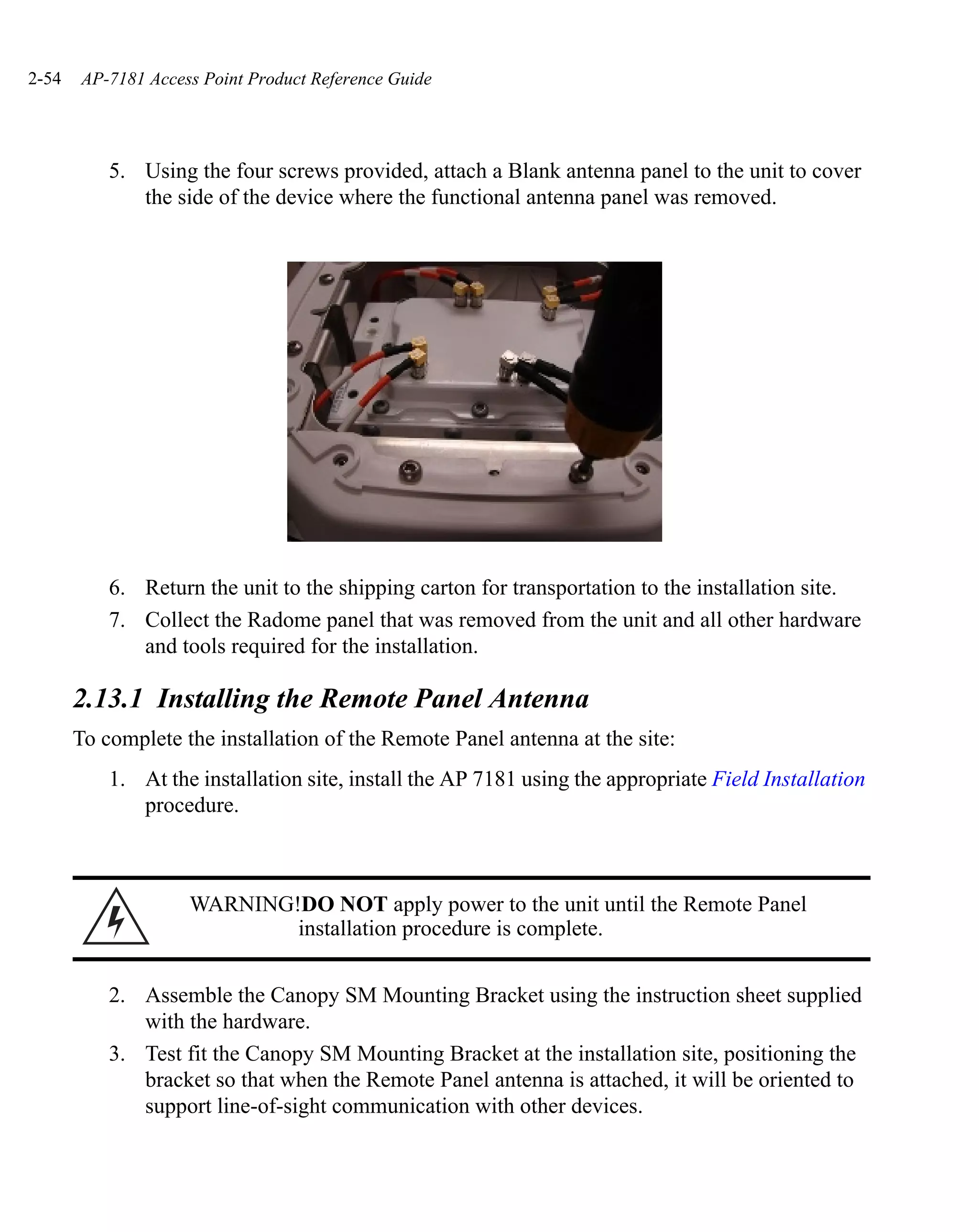
found by selecting Radio1 [802.11b/g/n] located under Network Configuration -
Wireless - Radio Configuration. The radio MAC address is located in the
properties window. Record this MAC address.](https://image.slidesharecdn.com/ap7181productreferenceguide-120807015046-phpapp02/75/Ap7181-product-referenceguide-121-2048.jpg)


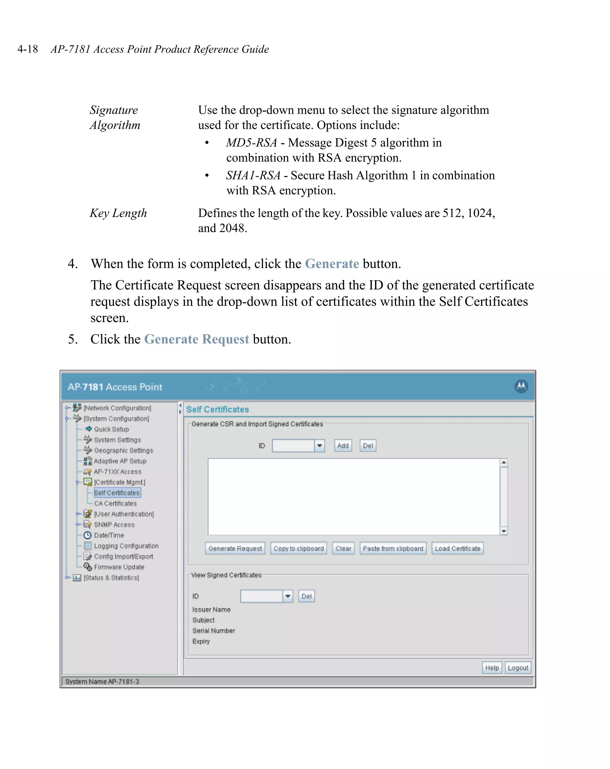
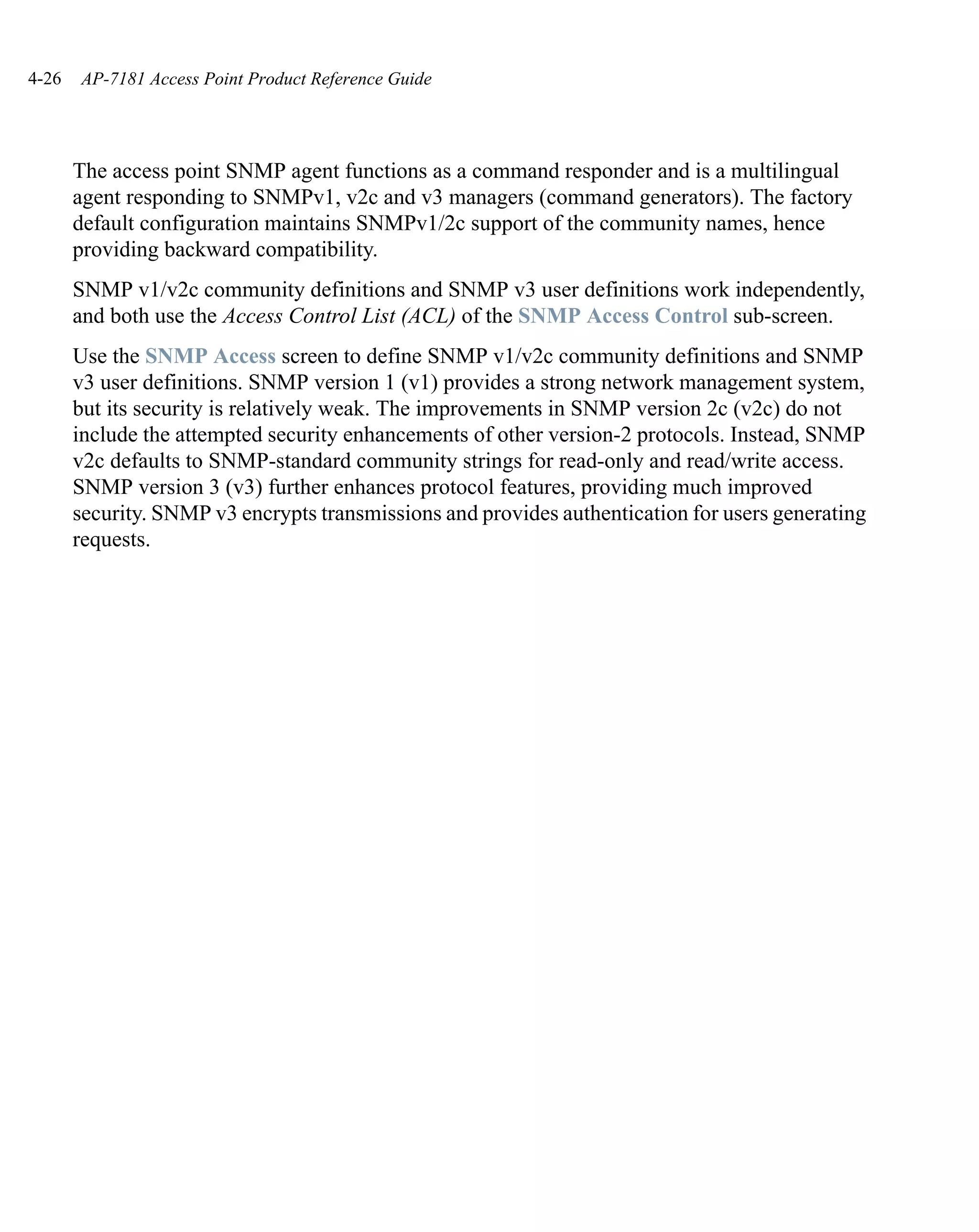
![System Configuration 4-51
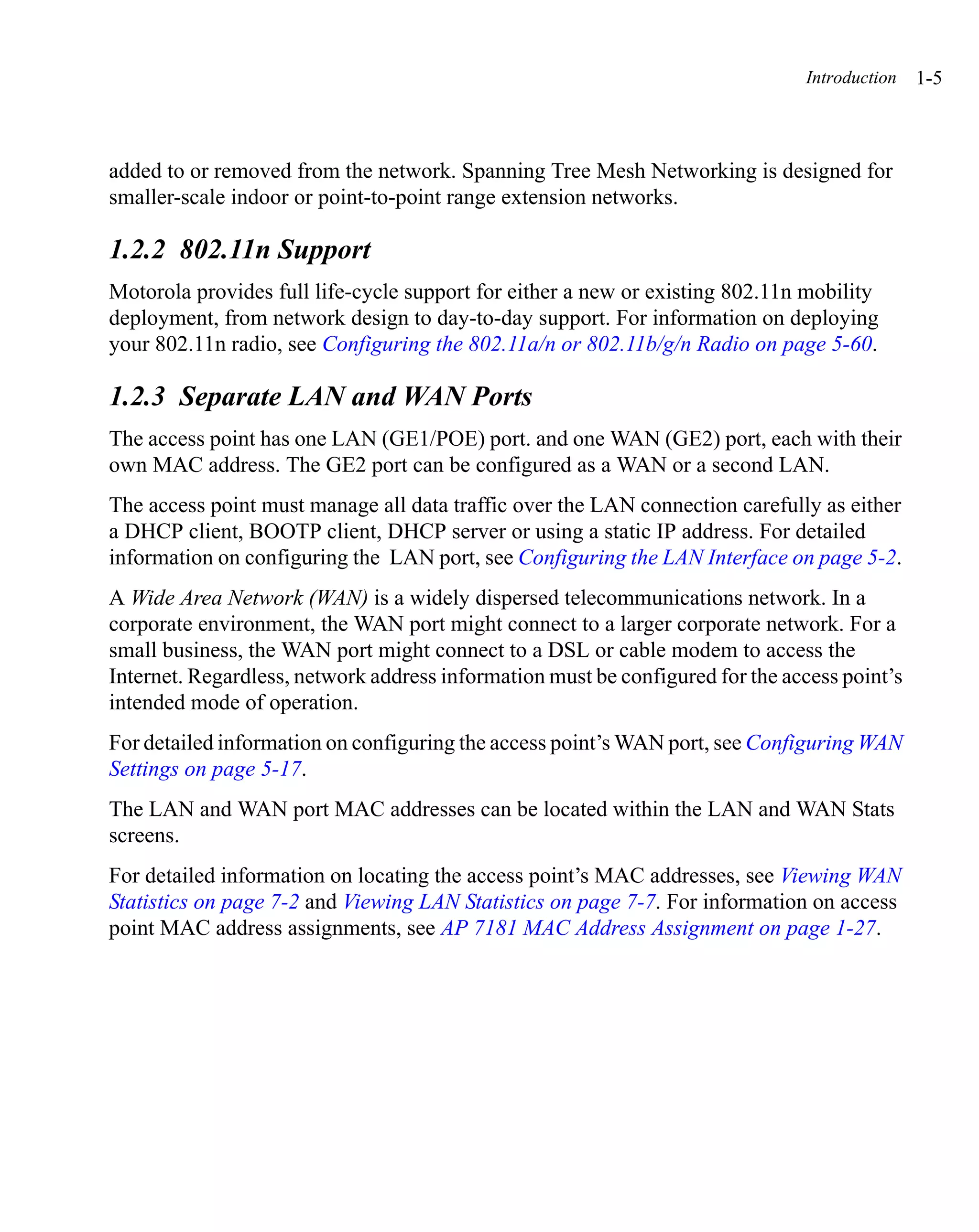
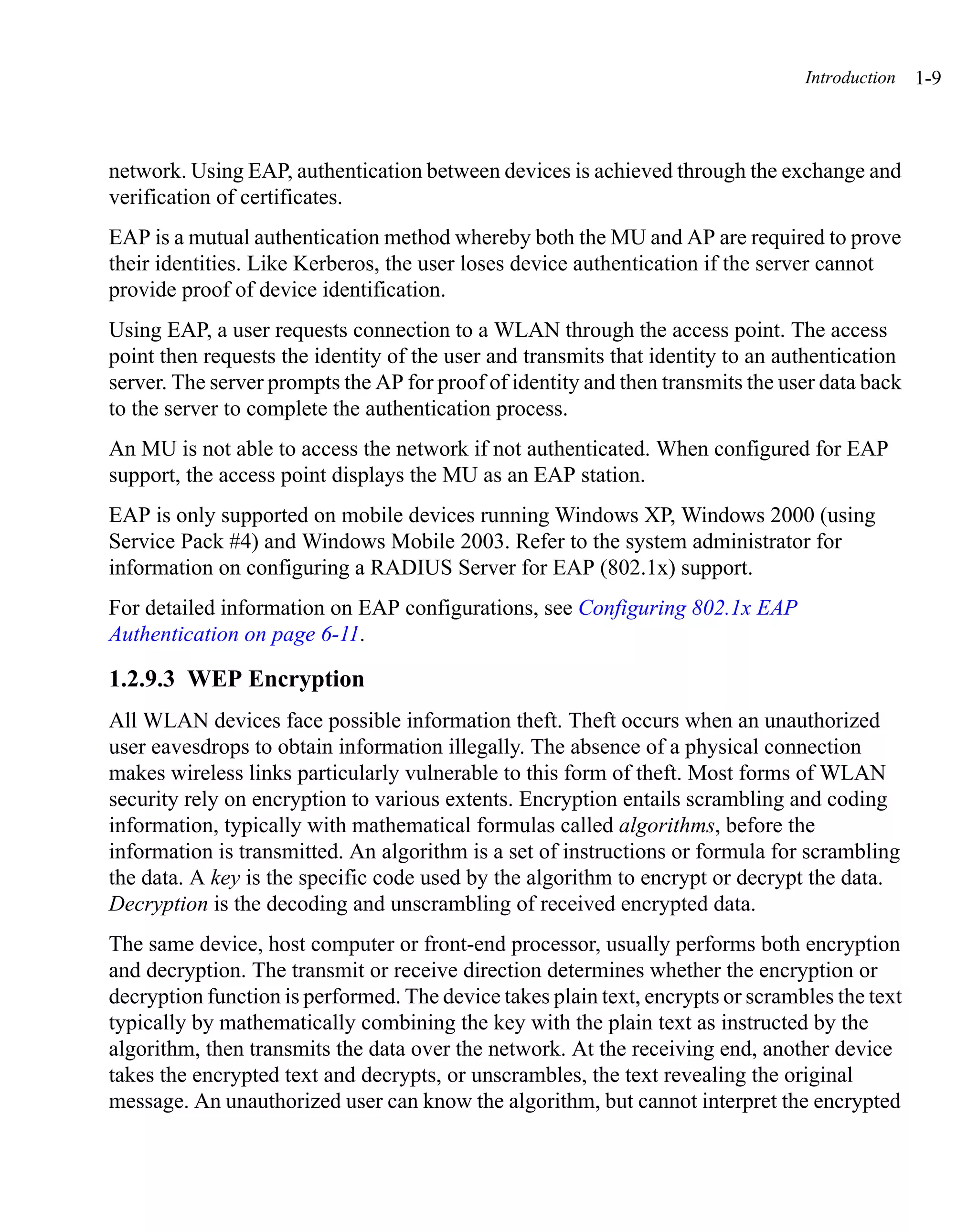
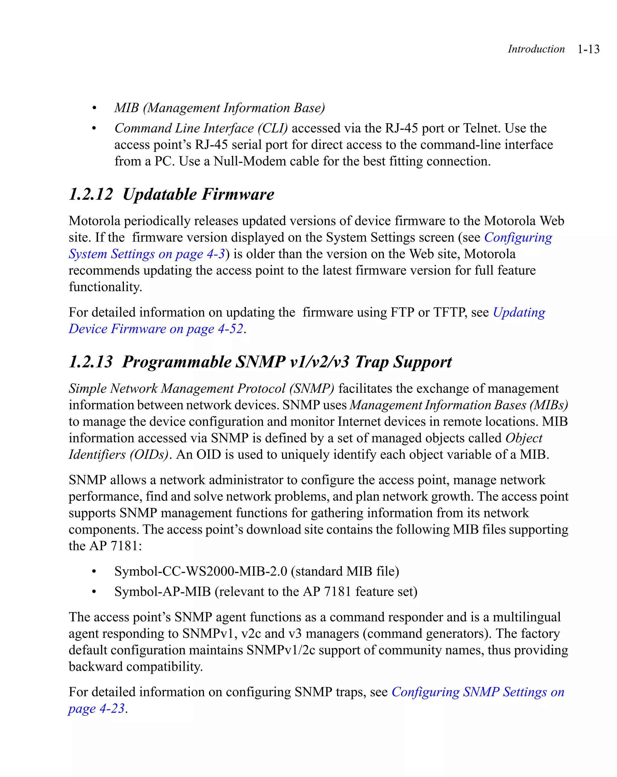
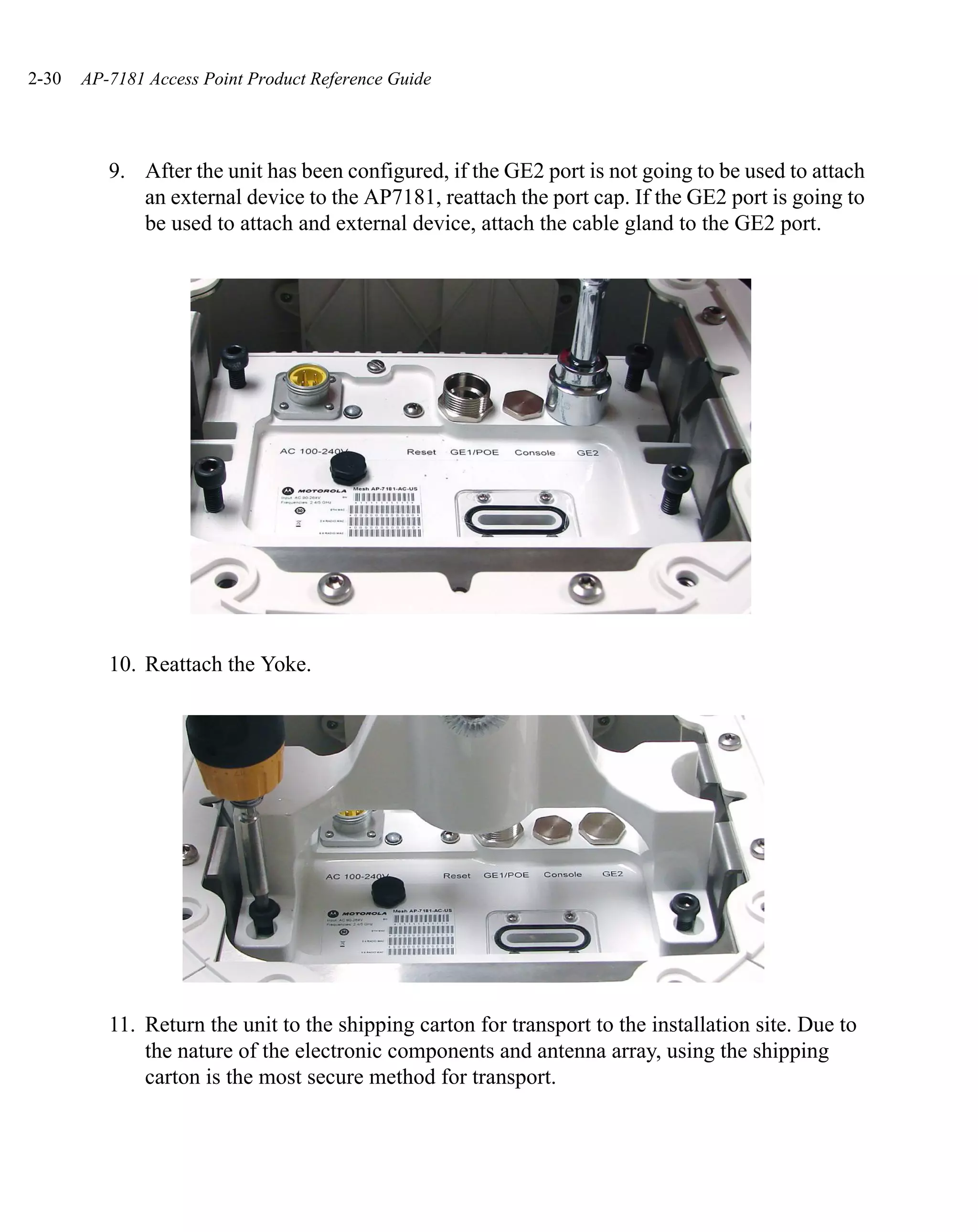
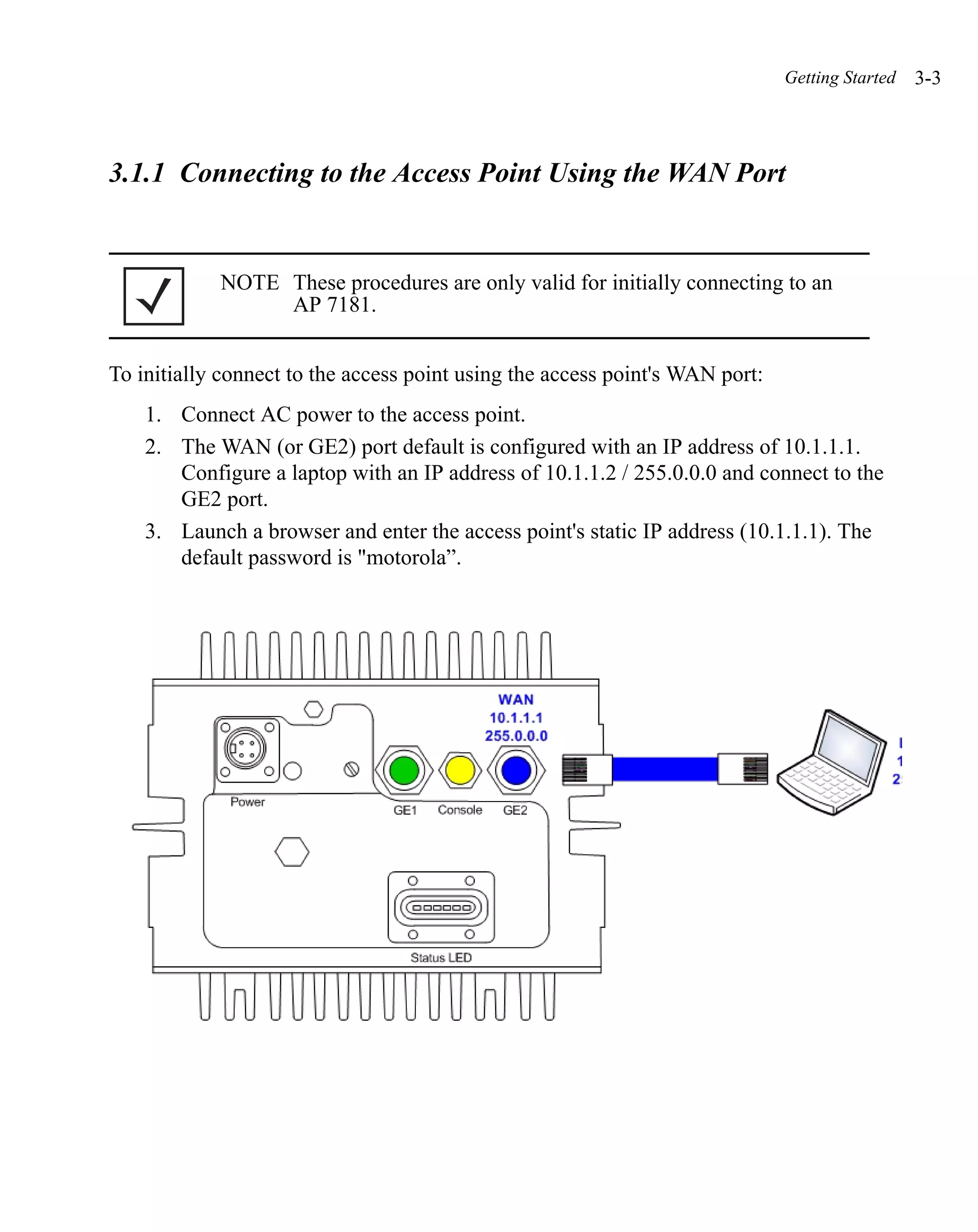
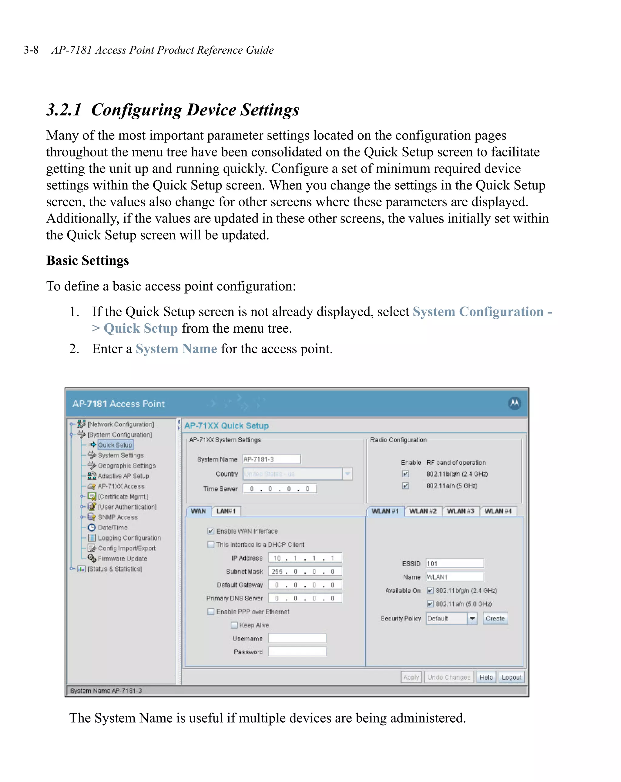
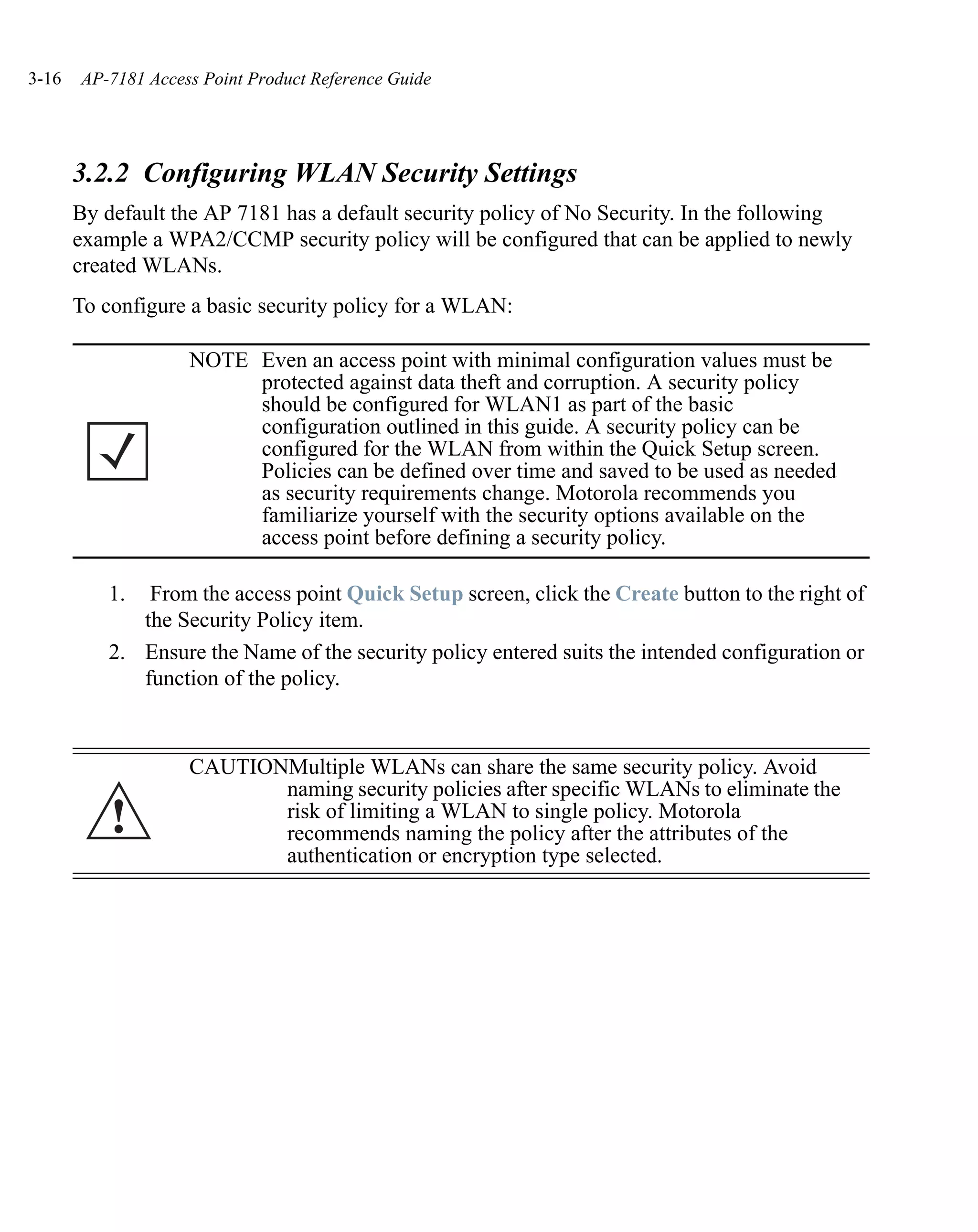
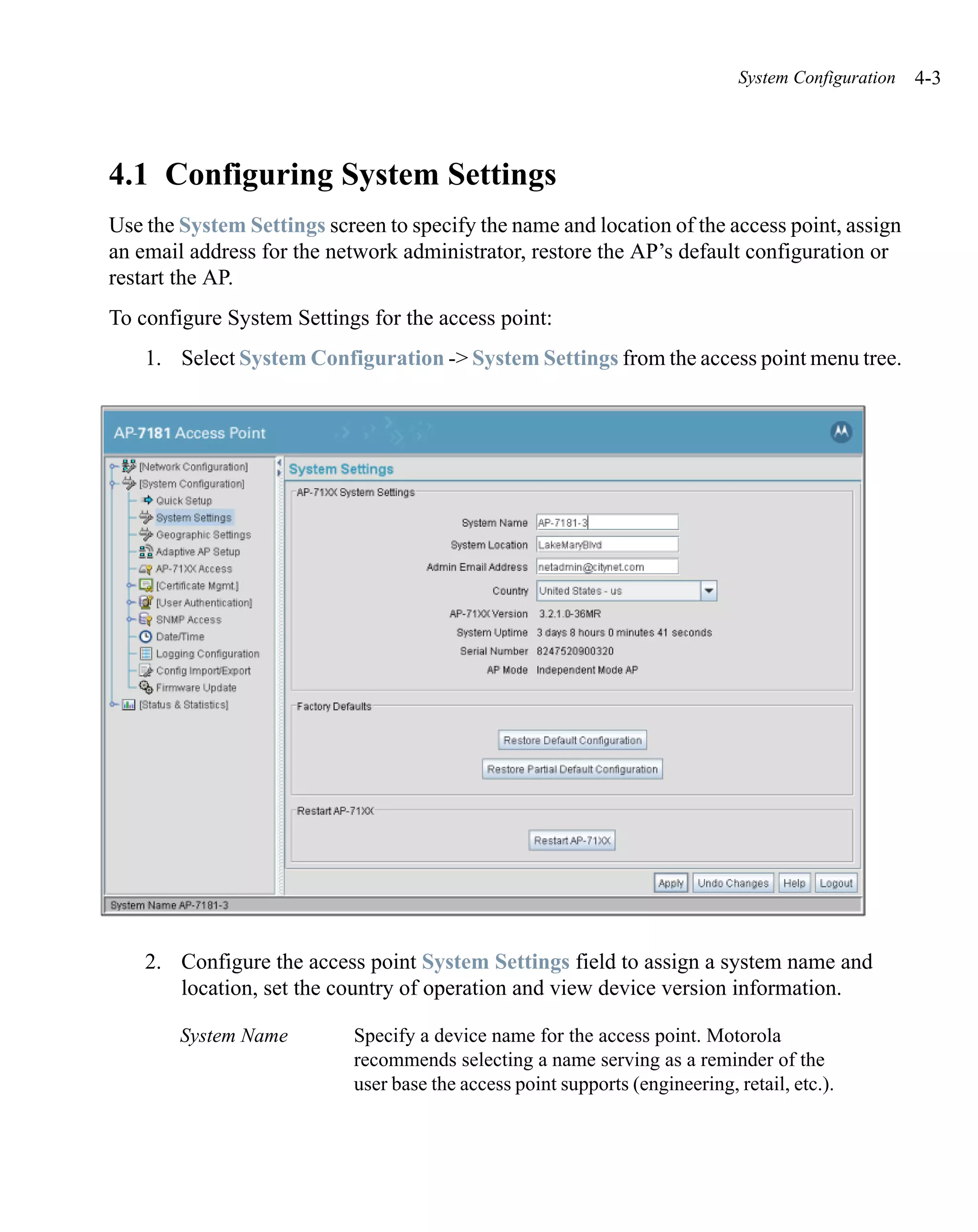
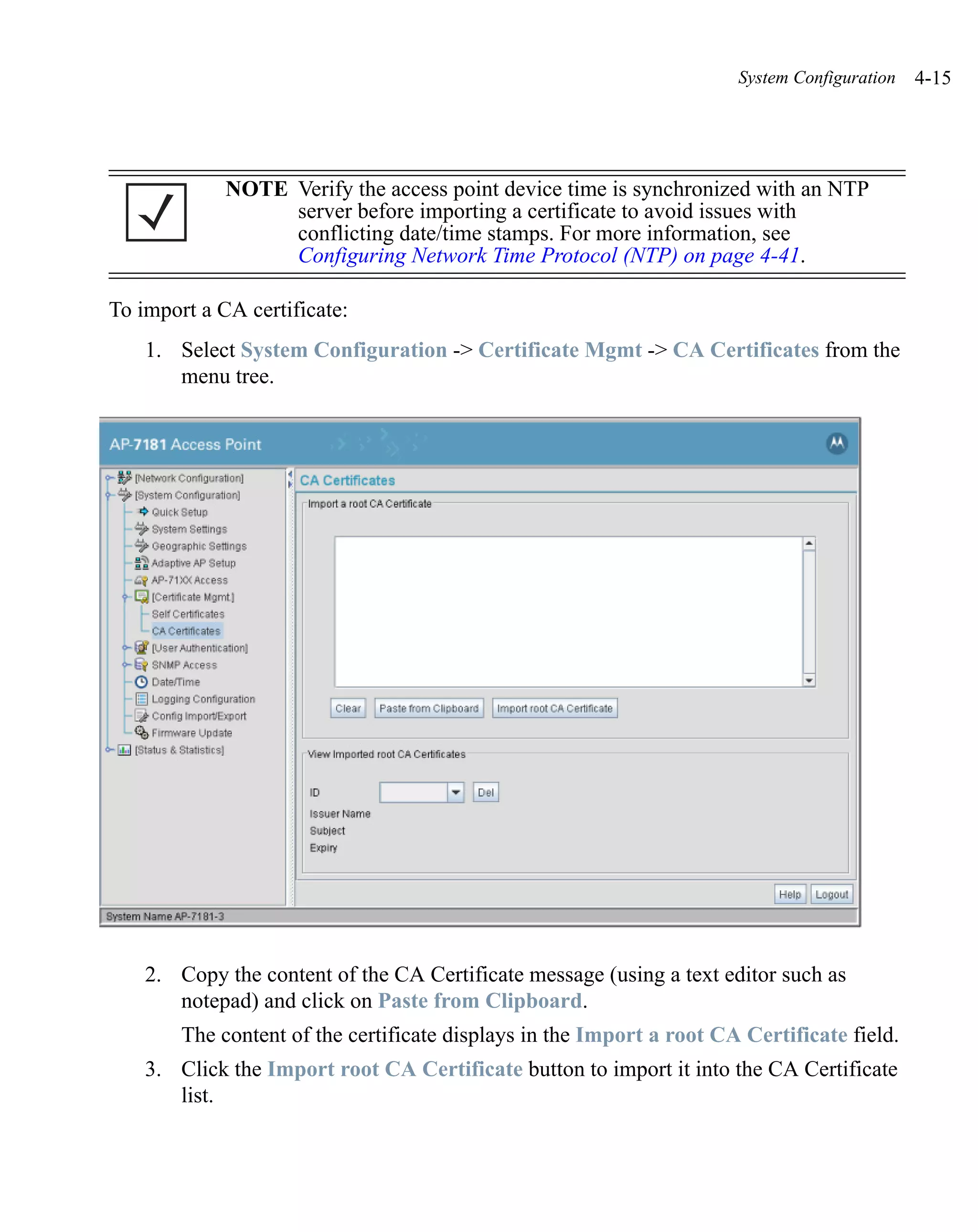
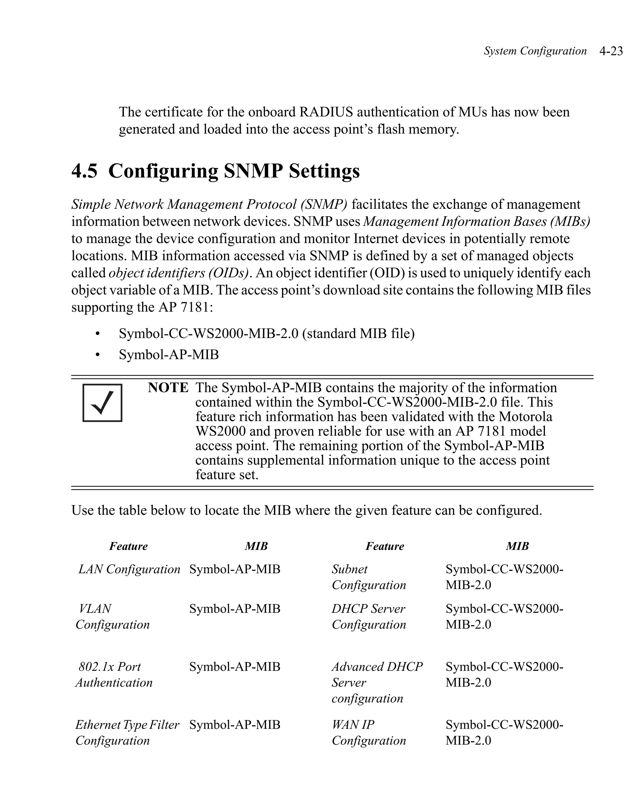
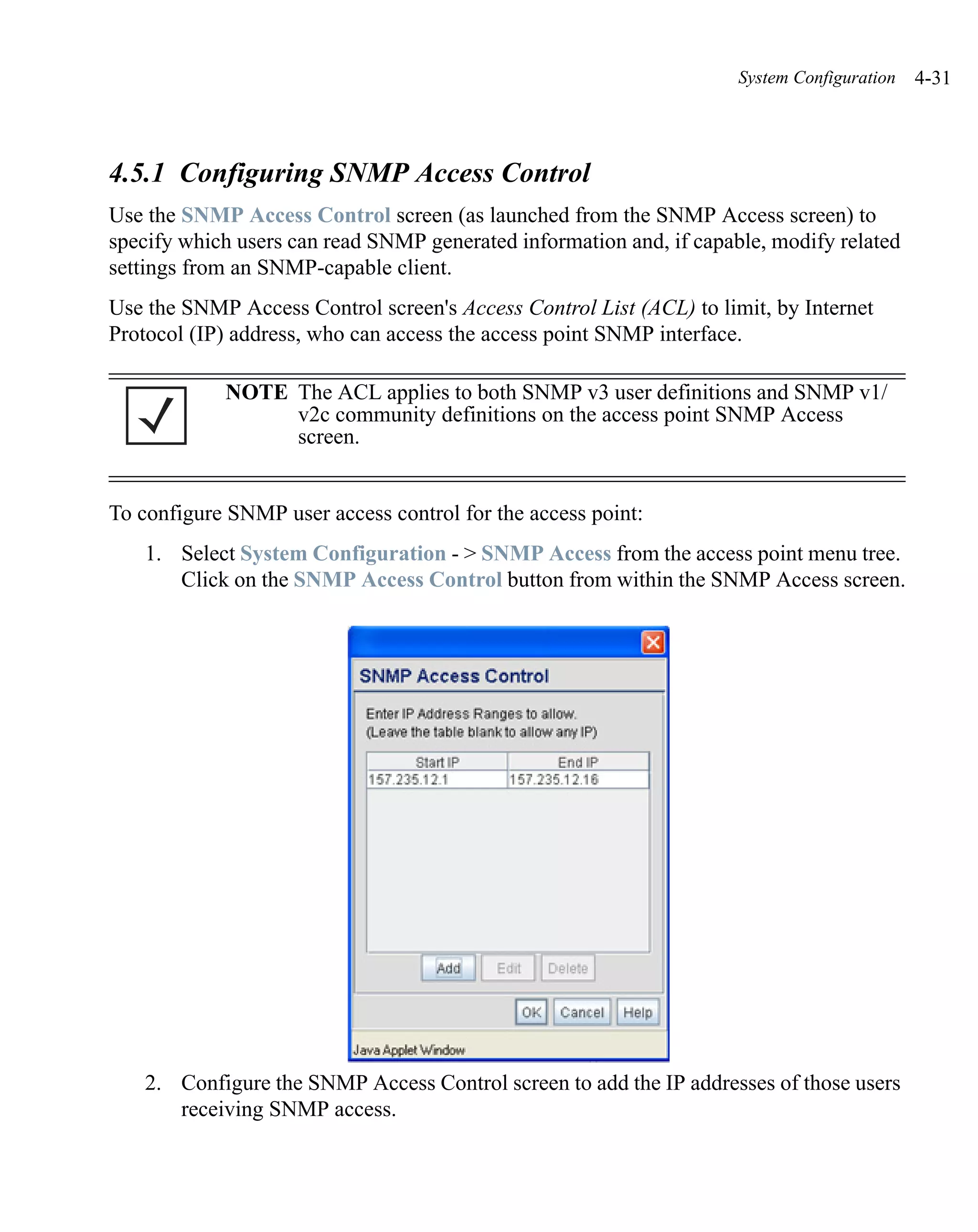
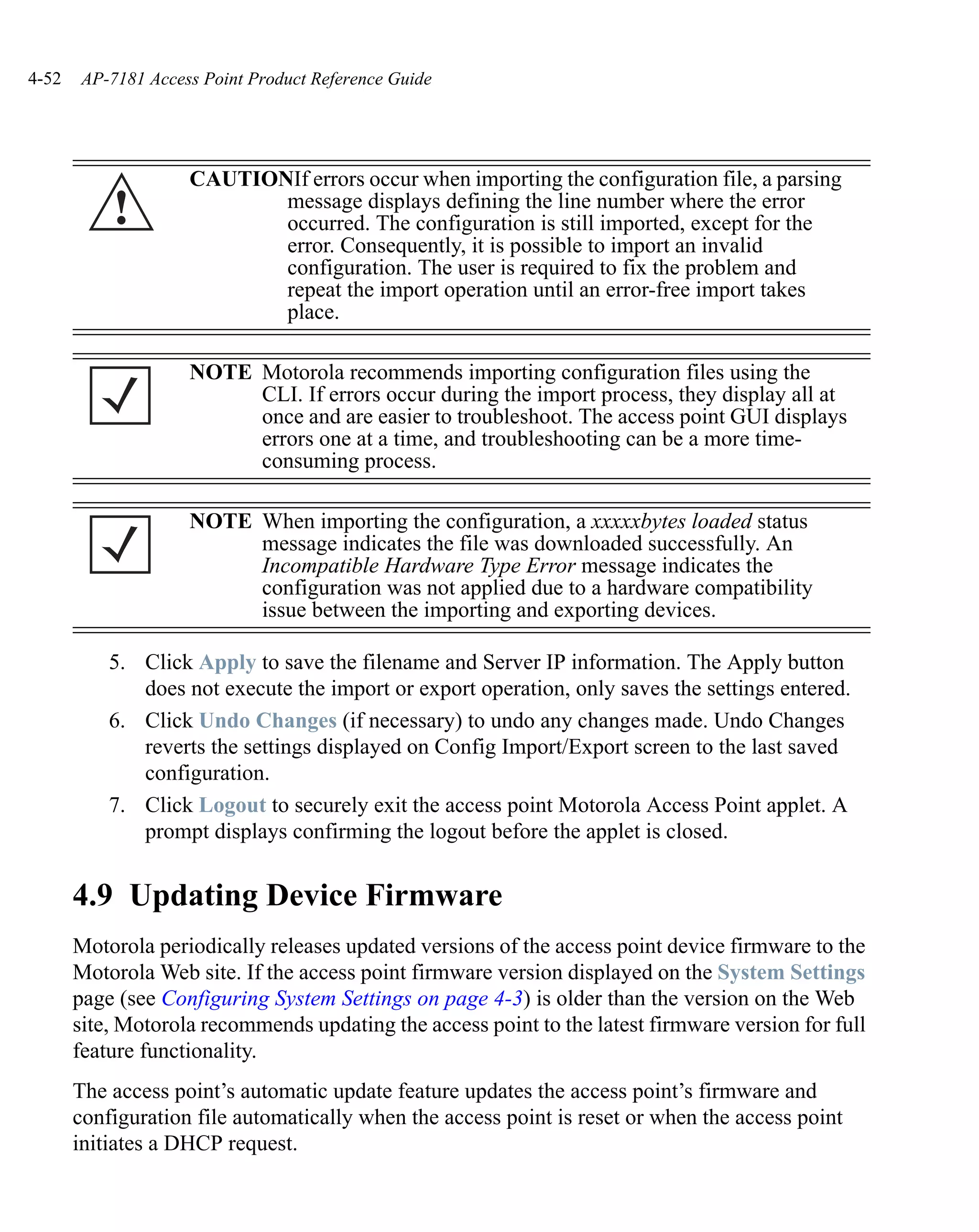
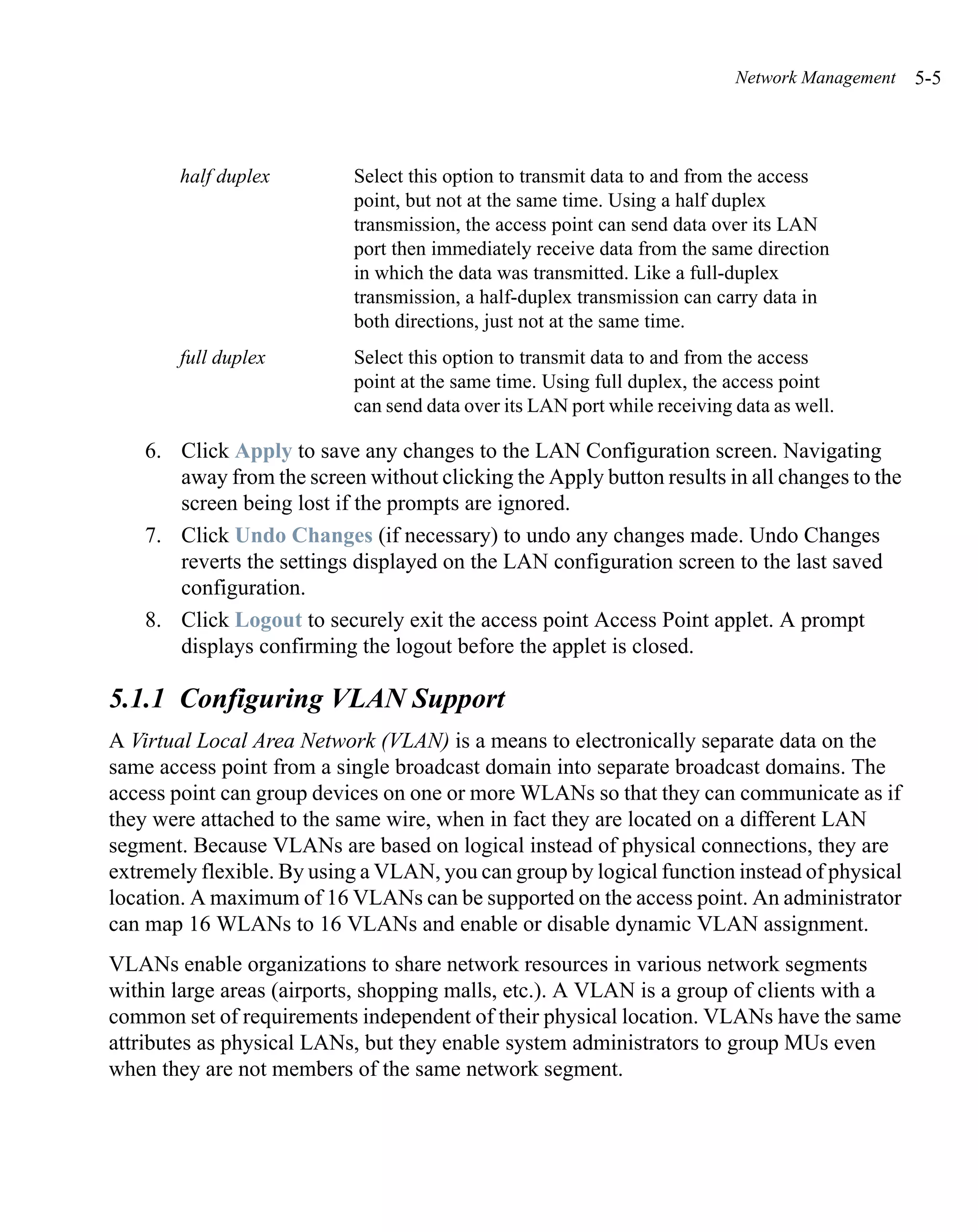
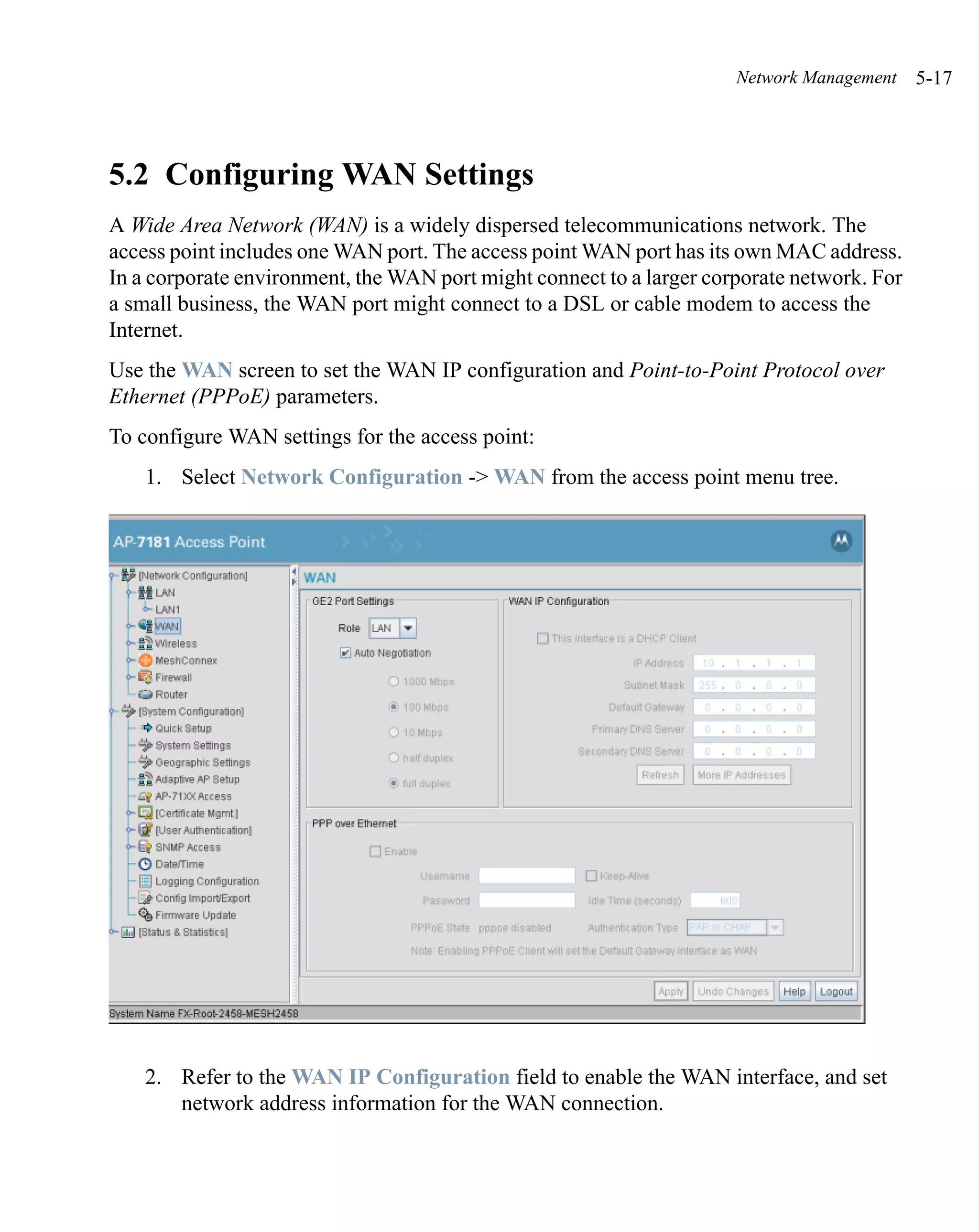
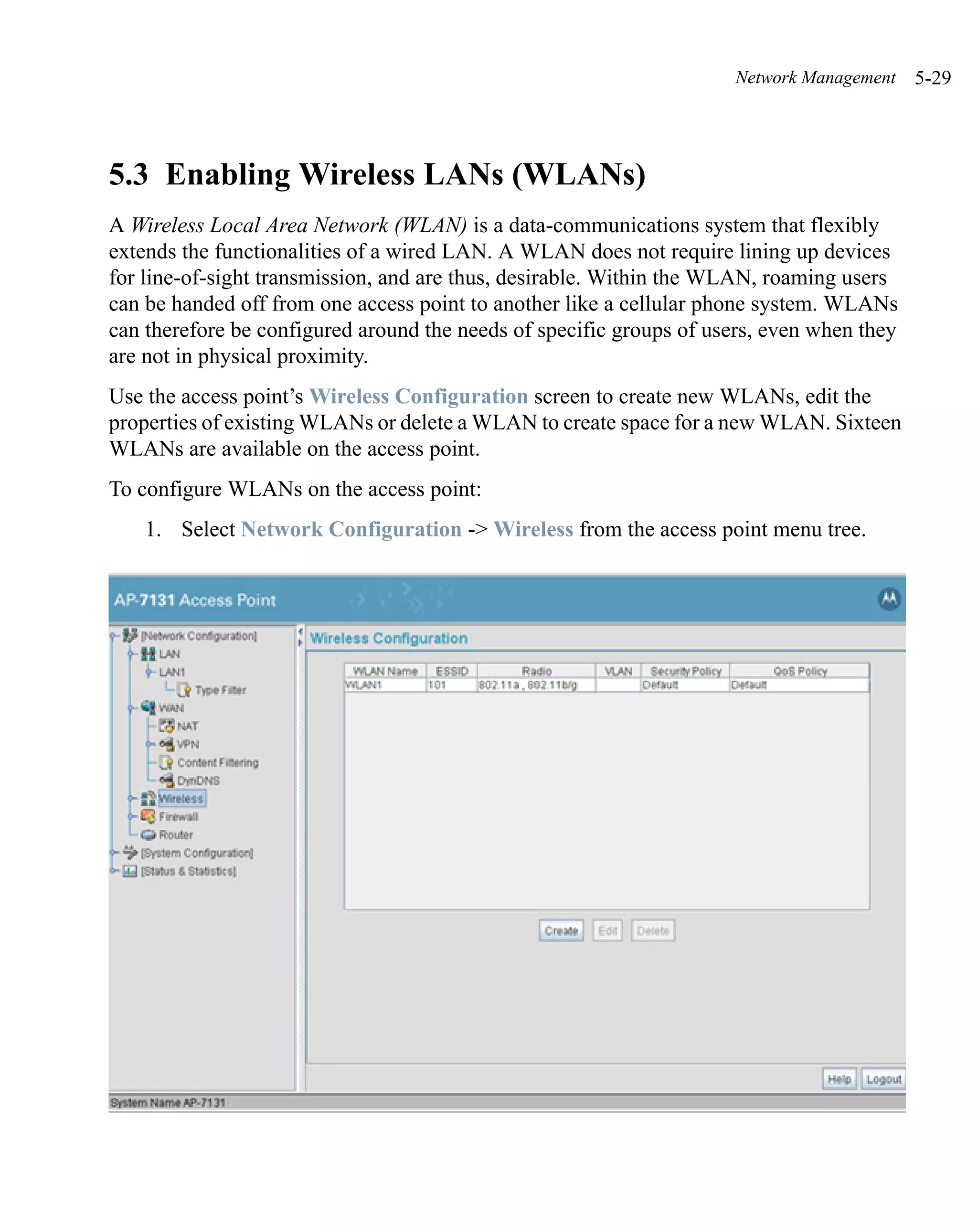
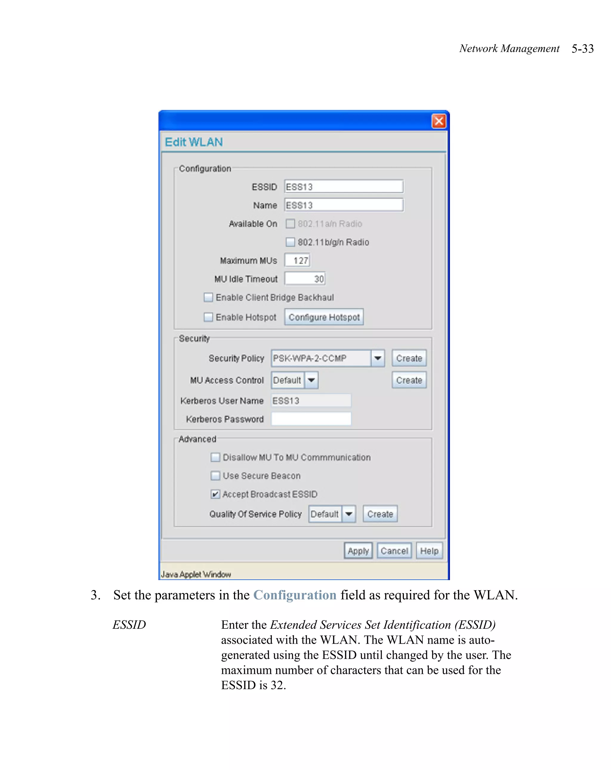
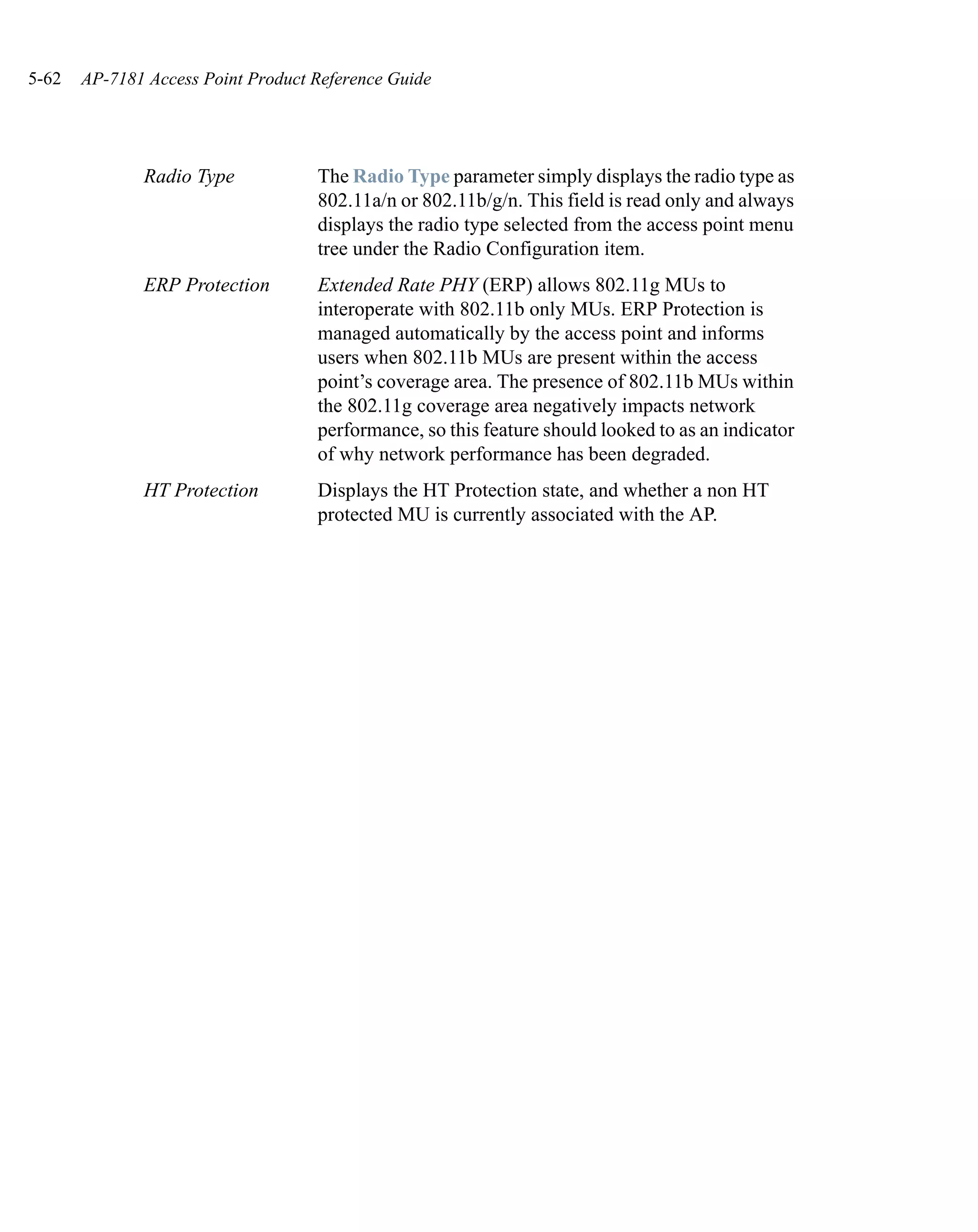
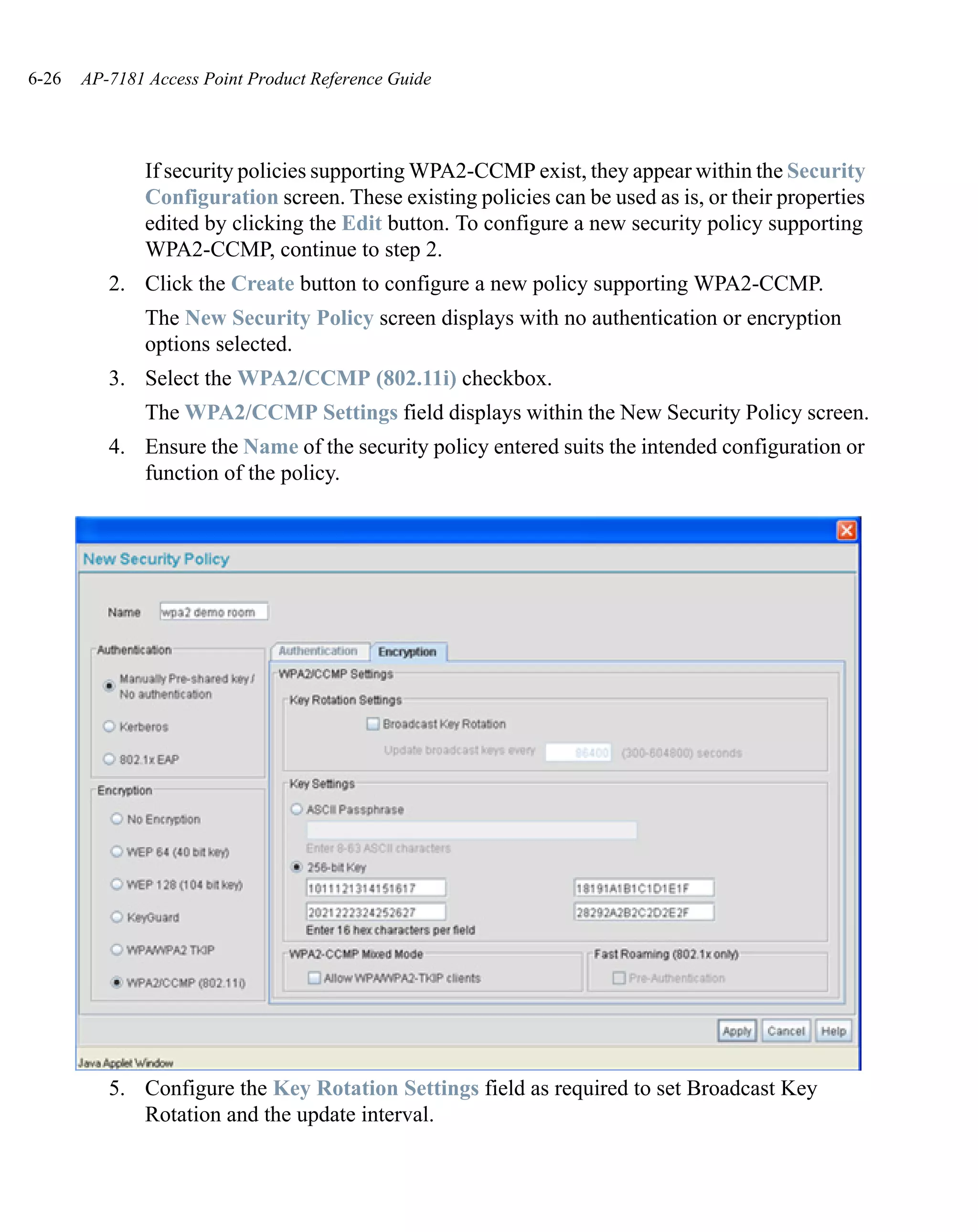
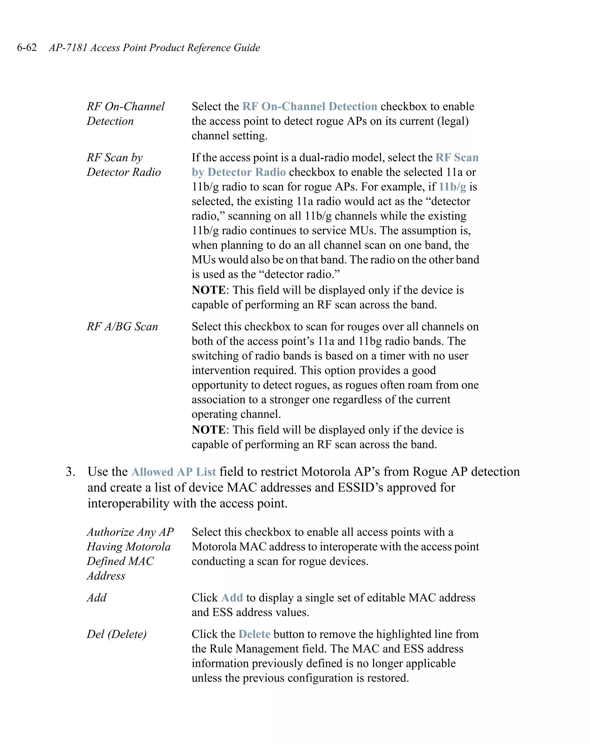
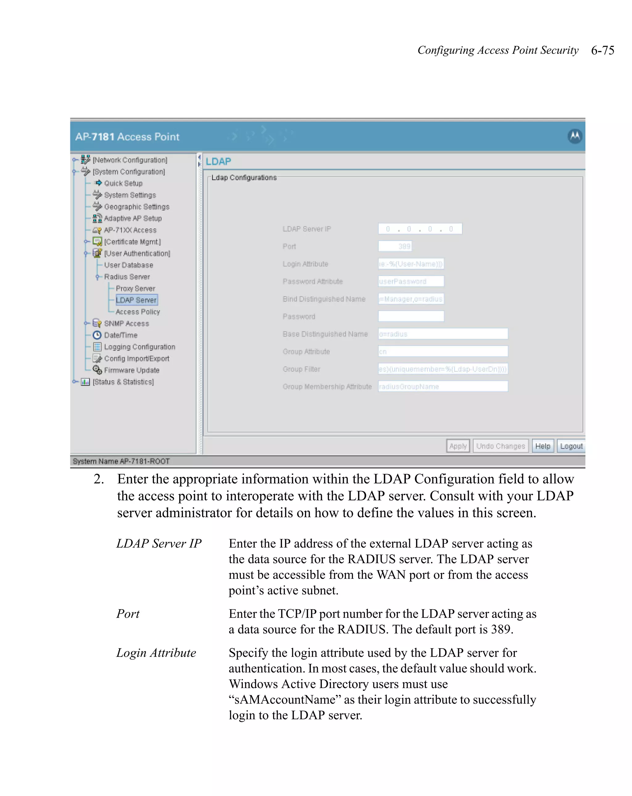
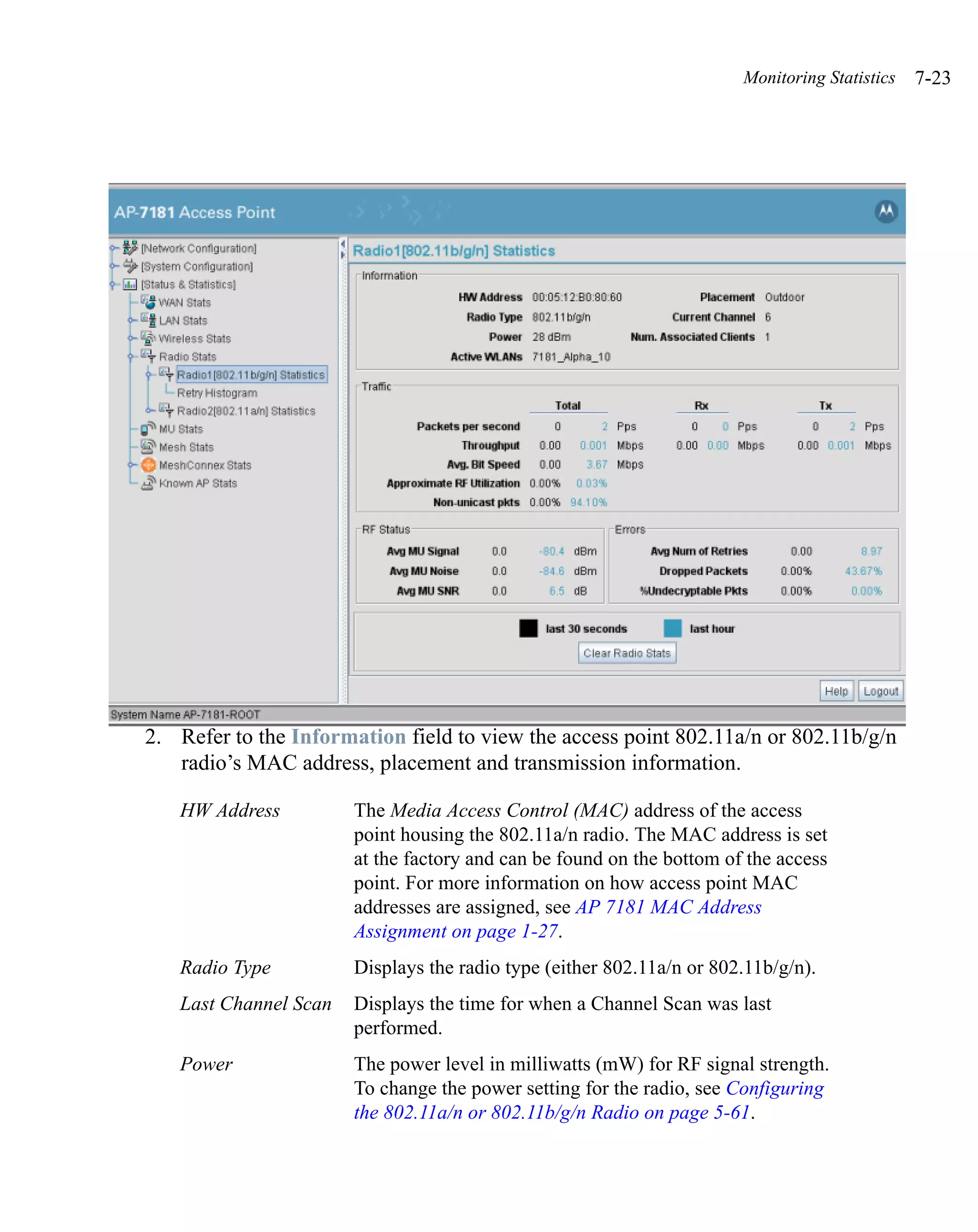
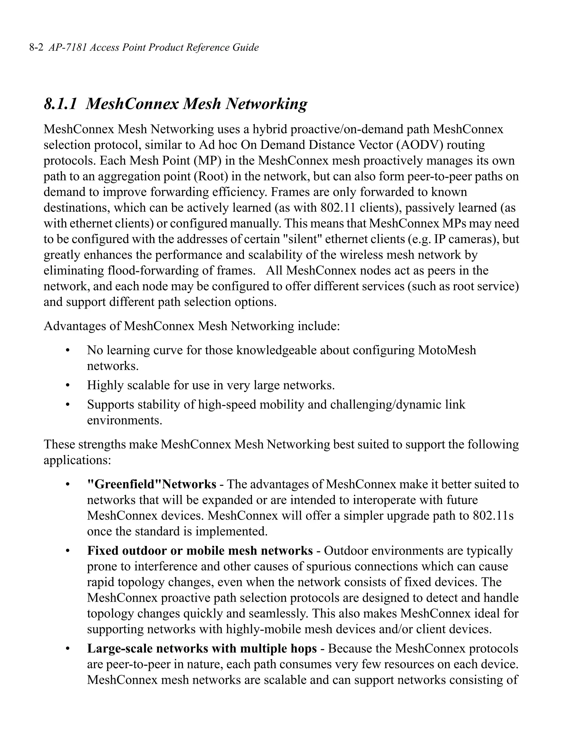
Upload and Apply A Click the Upload and Apply A Configuration File button
Configuration File to upload a configuration file to this access point using
HTTP.
Download Click the Download Configuration File button to
Configuration File download this access point’s configuration file using HTTP.
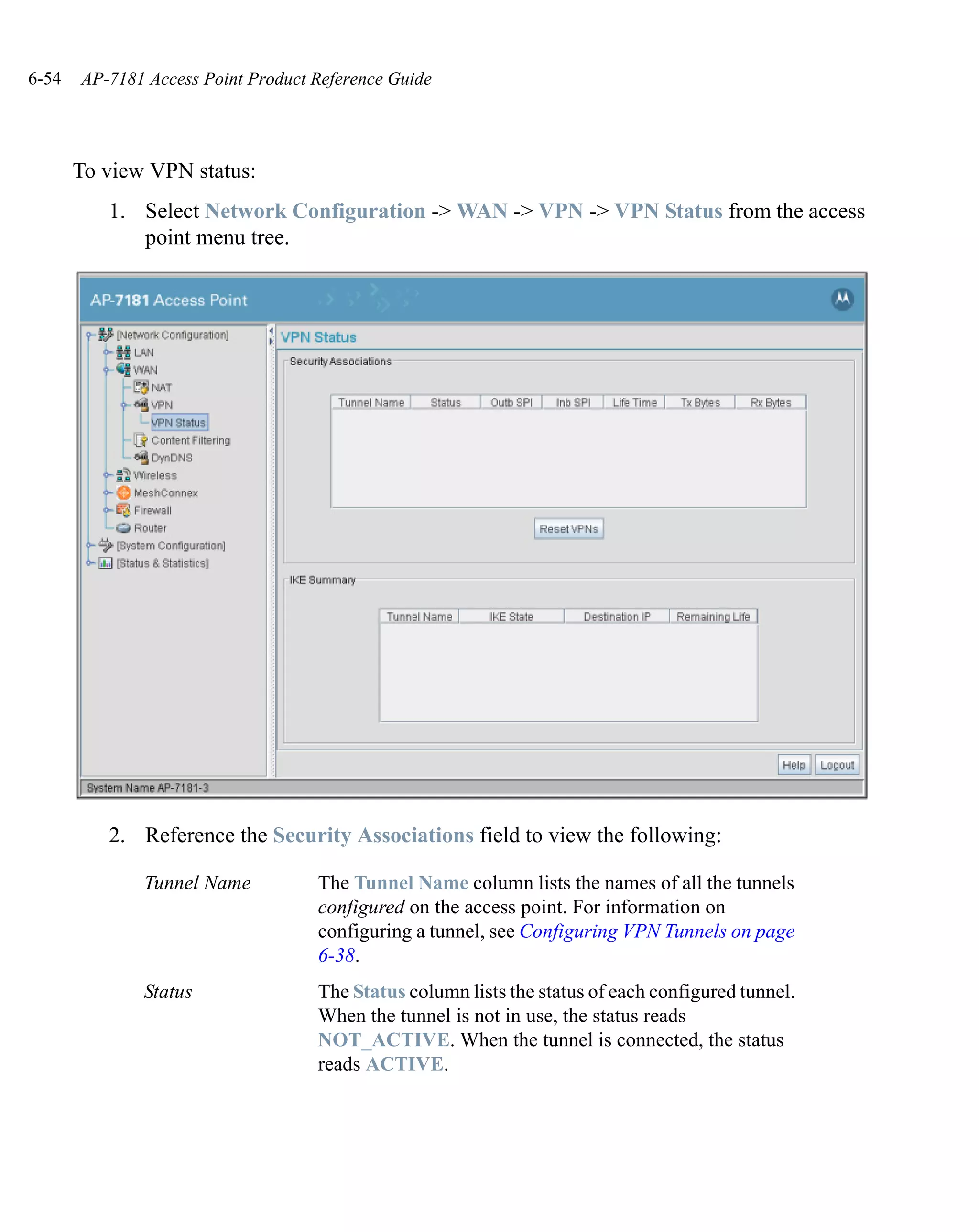
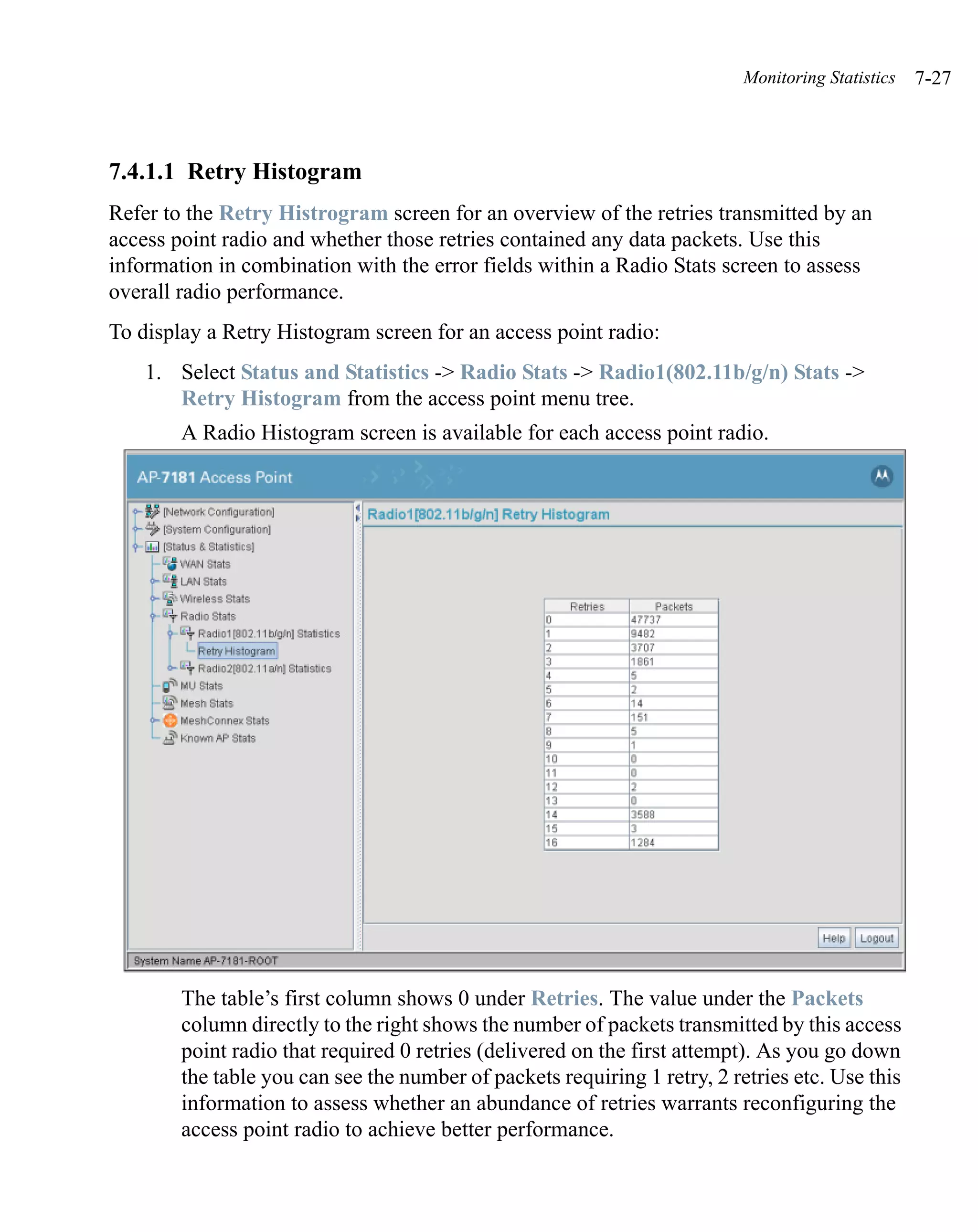
4. Refer to the Status field to assess the completion of the import/export operation.
Status After executing an operation (by clicking any of the buttons
in the window), check the Status field for a progress
indicator and messages about the success or errors in
executing the Import/Export operation. Possible status
messages include:
ambiguous input before marker: line <number >
unknown input before marker: line <number>
ignored input after marker: line <number>
additional input required after marker: line <number>
invalid input length: line <number>
error reading input: line <number>
import file from incompatible hardware type: line
<number>
[0] Import operation done
[1] Export operation done
[2] Import operation failed
[3] Export operation failed
[4] File transfer in progress
[5] File transfer failed
[6] File transfer done
Auto cfg update: Error in applying config
Auto cfg update: Error in getting config file
Auto cfg update: Aborting due to fw update failure
The <number> value appearing at the end of some messages
relates to the line of the configuration file where an error or
ambiguous input was detected.](https://image.slidesharecdn.com/ap7181productreferenceguide-120807015046-phpapp02/75/Ap7181-product-referenceguide-185-2048.jpg)


![Third Party Licensing B-9
negligent acts) or agreed to in writing, shall any Contributor be liable to You for damages, including
any direct, indirect, special, incidental, or consequential damages of any character arising as a result
of this License or out of the use or inability to use the Work (including but not limited to damages
for loss of goodwill, work stoppage, computer failure or malfunction, or any and all other
commercial damages or losses), even if such Contributor has been advised of the possibility of such
damages.
9. Accepting Warranty or Additional Liability. While redistributing the Work or Derivative Works
thereof, You may choose to offer, and charge a fee for, acceptance of support, warranty, indemnity,
or other liability obligations and/or rights consistent with this License. However, in accepting such
obligations, You may act only on Your own behalf and on Your sole responsibi ity, not on behalf of
any other Contributor, and only if You agree to indemnify, defend, and hold each Contributor
harmless for any liability incurred by, or claims asserted against, such Contributor by reason of your
accepting any such warranty or additional liability.
END OF TERMS AND CONDITIONS
APPENDIX: How to apply the Apache License to your work.
To apply the Apache License to your work, attach the following boilerplate notice, with the fields
enclosed by brackets "[]" replaced with your own identifying information. (Don't include the
brackets!) The text should be enclosed in the appropriate omment syntax for the file format. We also
recommend that a file or class name and description of purpose be included on the same "printed
page" as the copyright notice for easier identification within third-party archives.
Copyright [yyyy] [name of copyright owner]
Licensed under the Apache License, Version 2.0 (the "License"); you may not use this file except in
compliance with the License. You may obtain a copy of the License at
http://www.apache.org/licenses/LICENSE-2.0
Unless required by applicable law or agreed to in writing, software distributed under the License is
distributed on an "AS IS" BASIS, WITHOUT WARRANTIES OR CONDITIONS OF ANY KIND,
either express or implied. See the License for the specific language governing permissions and
limitations under the License.
Internet Systems Consortiums, Inc.
Copyright (C) 1996-2003 Internet Software Consortium.
Permission to use, copy, modify, and distribute this software for any purpose with or without fee is
hereby granted, provided that the above copyright notice and this permission notice appear in all
copies.
THE SOFTWARE IS PROVIDED "AS IS" AND ISC DISCLAIMS ALL WARRANTIES
REGARD TO THIS SOFTWARE INCLUDING ALL IMPLIED WARRANTIES OF
MERCHANTABILITY AND FITNESS. IN NO EVENT SHALL ISC BE LIABLE FOR ANY](https://image.slidesharecdn.com/ap7181productreferenceguide-120807015046-phpapp02/75/Ap7181-product-referenceguide-455-2048.jpg)
![B-30 AP-7181 Access Point Product Reference Guide
Redistribution and use in source and binary forms, with or without modification, are
permitted provided that the following conditions are met:
1. Redistributions of source code must retain the copyright notice, this list of conditions and
the following disclaimer.
2. Redistributions in binary form must reproduce the above copyright notice, this list of
conditions and the following disclaimer in the documentation and/or other materials
provided with the distribution.
3. All advertising materials mentioning features or use of this software must display the
following acknowledgement: "This product includes cryptographic software written by
Eric Young (eay@cryptsoft.com)". The word 'cryptographic' can be left out if the rouines
from the library being used are not cryptographic related :-).
4. If you include any Windows specific code (or a derivative thereof) from the apps
directory (application code) you must include an acknowledgement: "This product includes
software written by Tim Hudson (tjh@cryptsoft.com)"
THIS SOFTWARE IS PROVIDED BY ERIC YOUNG ``AS IS'' AND ANY EXPRESS
OR IMPLIED WARRANTIES, INCLUDING, BUT NOT LIMITED TO, THE IMPLIED
WARRANTIES OF MERCHANTABILITY AND FITNESS FOR A PARTICULAR
PURPOSE ARE DISCLAIMED. IN NO EVENT SHALL THE AUTHOR OR
CONTRIBUTORS BE LIABLE FOR ANY DIRECT, INDIRECT, INCIDENTAL,
SPECIAL, EXEMPLARY, OR CONSEQUENTIAL DAMAGES (INCLUDING, BUT
NOT LIMITED TO, PROCUREMENT OF SUBSTITUTE GOODS OR SERVICES;
LOSS OF USE, DATA, OR PROFITS; OR BUSINESS INTERRUPTION) HOWEVER
CAUSED AND ON ANY THEORY OF LIABILITY, WHETHER IN CONTRACT,
STRICT LIABILITY, OR TORT (INCLUDING NEGLIGENCE OR OTHERWISE)
ARISING IN ANY WAY OUT OF THE USE OF THIS SOFTWARE, EVEN IF ADVISED
OF THE POSSIBILITY OF SUCH DAMAGE.
The licence and distribution terms for any publically available version or derivative of this
code cannot be changed. i.e. this code cannot simply be copied and put under another
distribution licence s[including the GNU Public Licence.]](https://image.slidesharecdn.com/ap7181productreferenceguide-120807015046-phpapp02/75/Ap7181-product-referenceguide-476-2048.jpg)


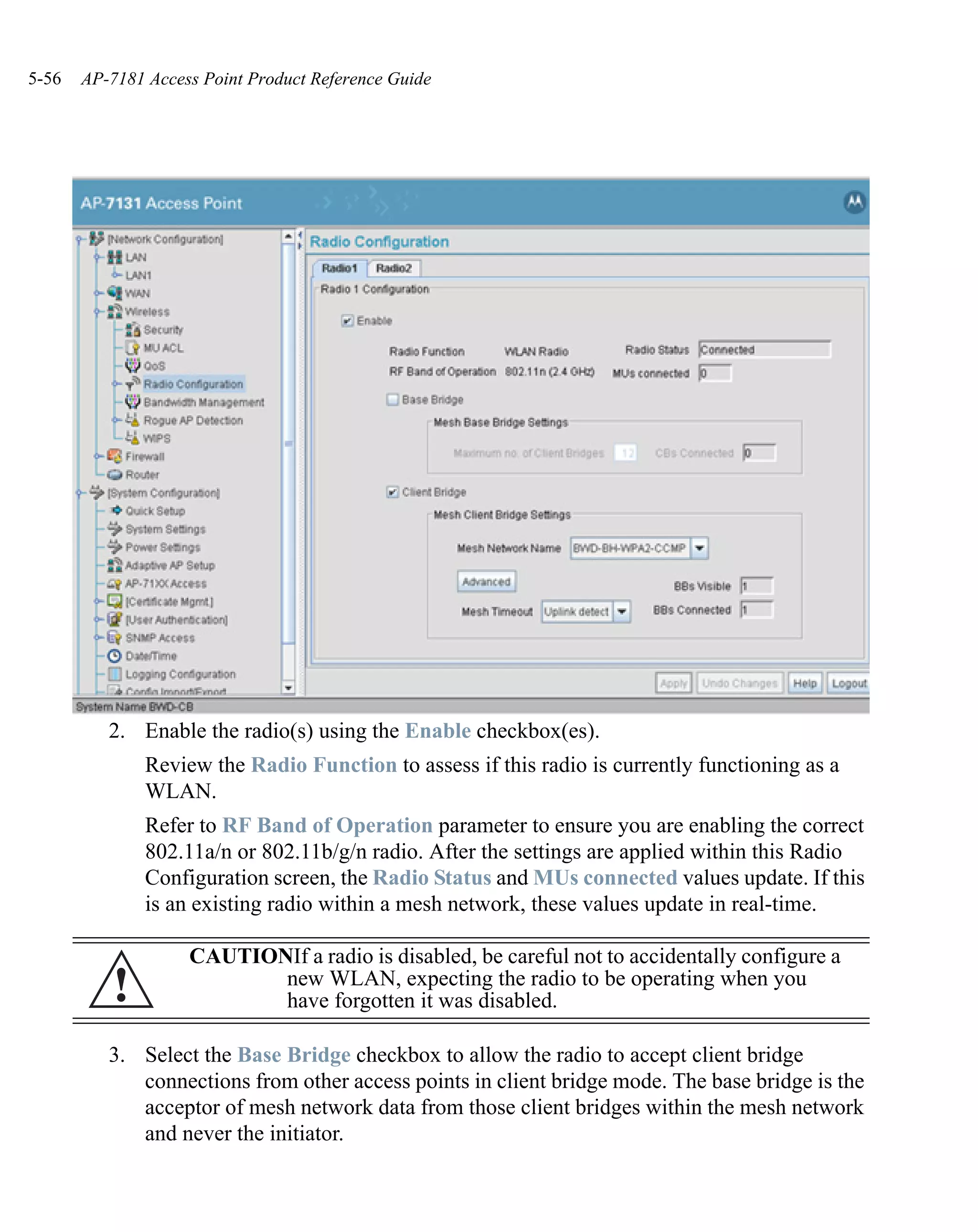
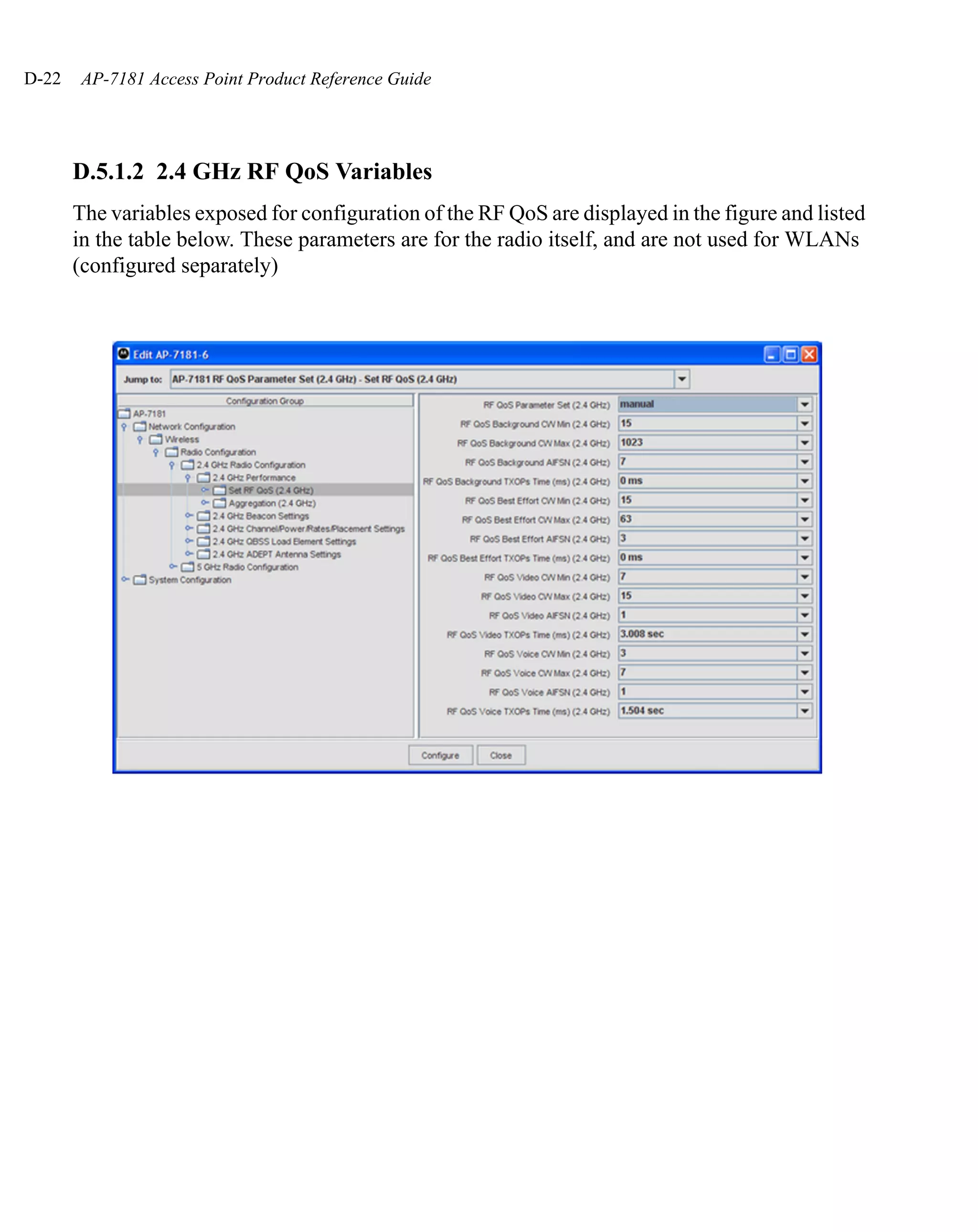
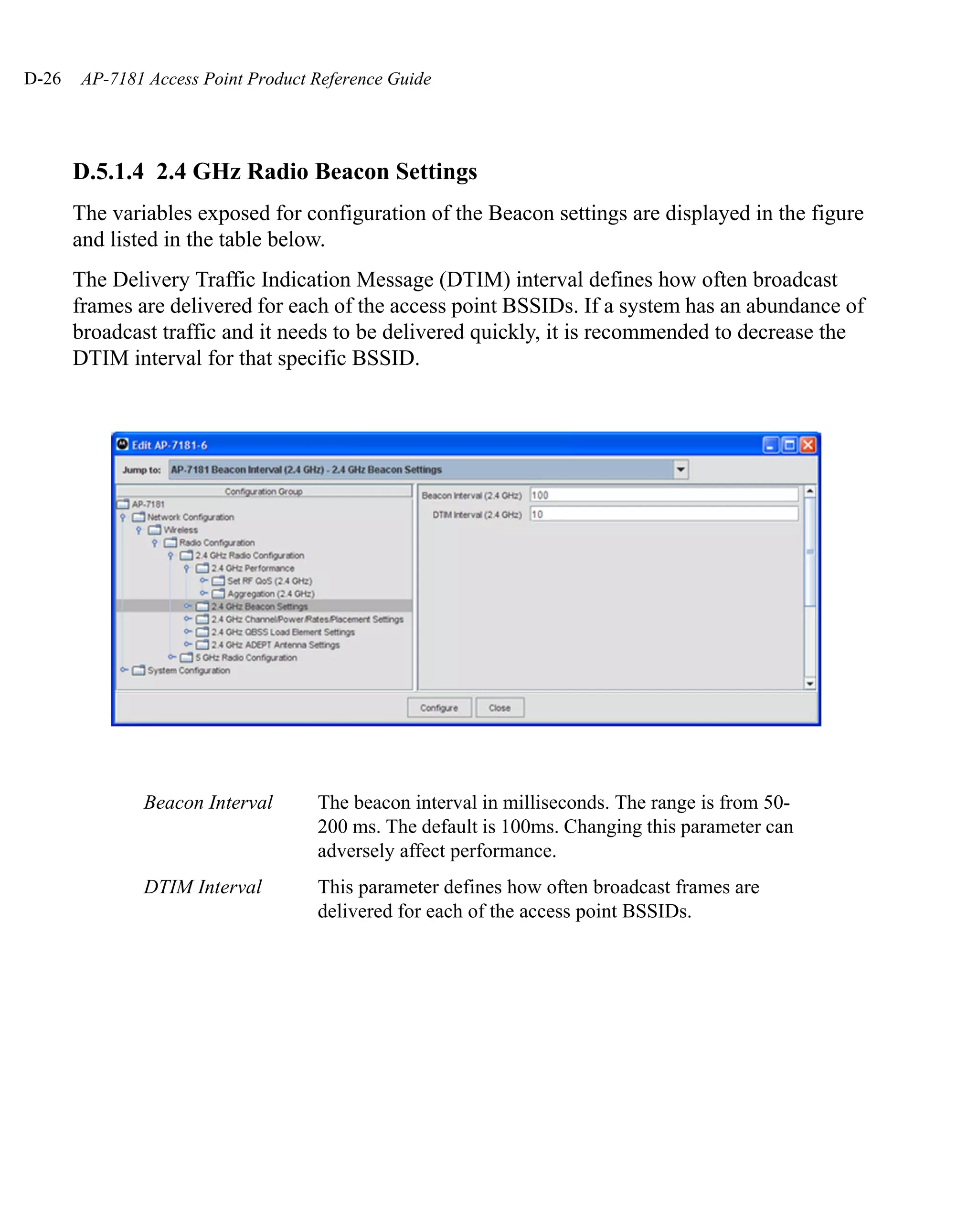
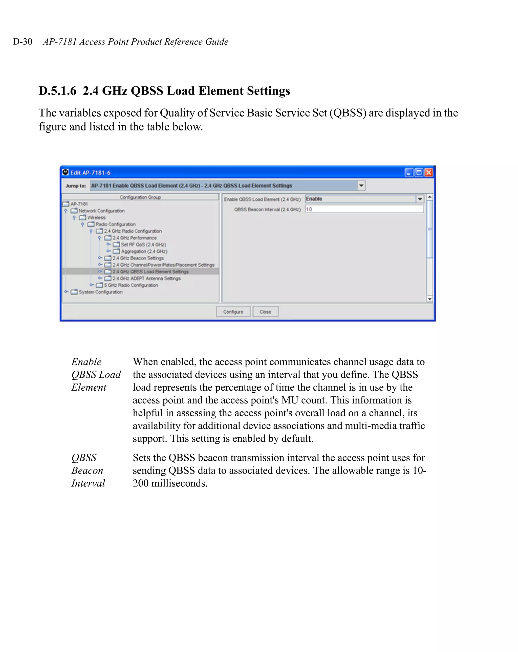
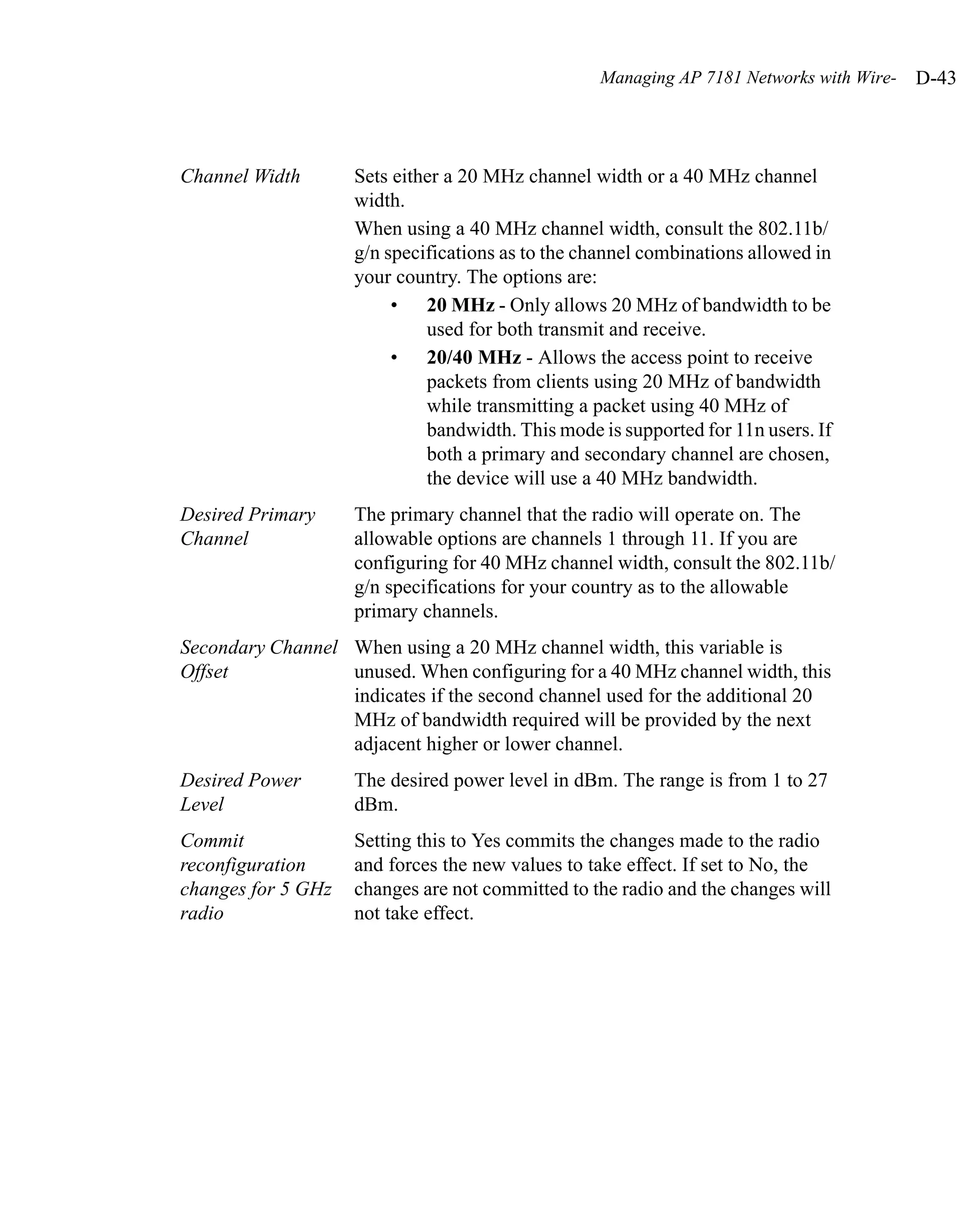
![D-20 AP-7181 Access Point Product Reference Guide
D.5 2.4 GHz Radio Configuration
The settings for the 2.4 GHz Radio Configuration are shown in the Network Configuration
/ Radio Configuration / Radio1[802.11b/g/n] tree item in the AP 7181 web page
configuration. The enable/disable configuration and some of the reporting items from the
Network Configuration / Radio Configuration tree item in the AP 7181 web page
configuration are also supported.
D.5.1 2.4 GHz Configurable Variables
Only one variable is exposed to enable the 2.4 GHz radio
:
Radio Enable This setting enables or disables the 2.4 GHz radio. When
disabled, the radio will not transmit or receive.](https://image.slidesharecdn.com/ap7181productreferenceguide-120807015046-phpapp02/75/Ap7181-product-referenceguide-506-2048.jpg)
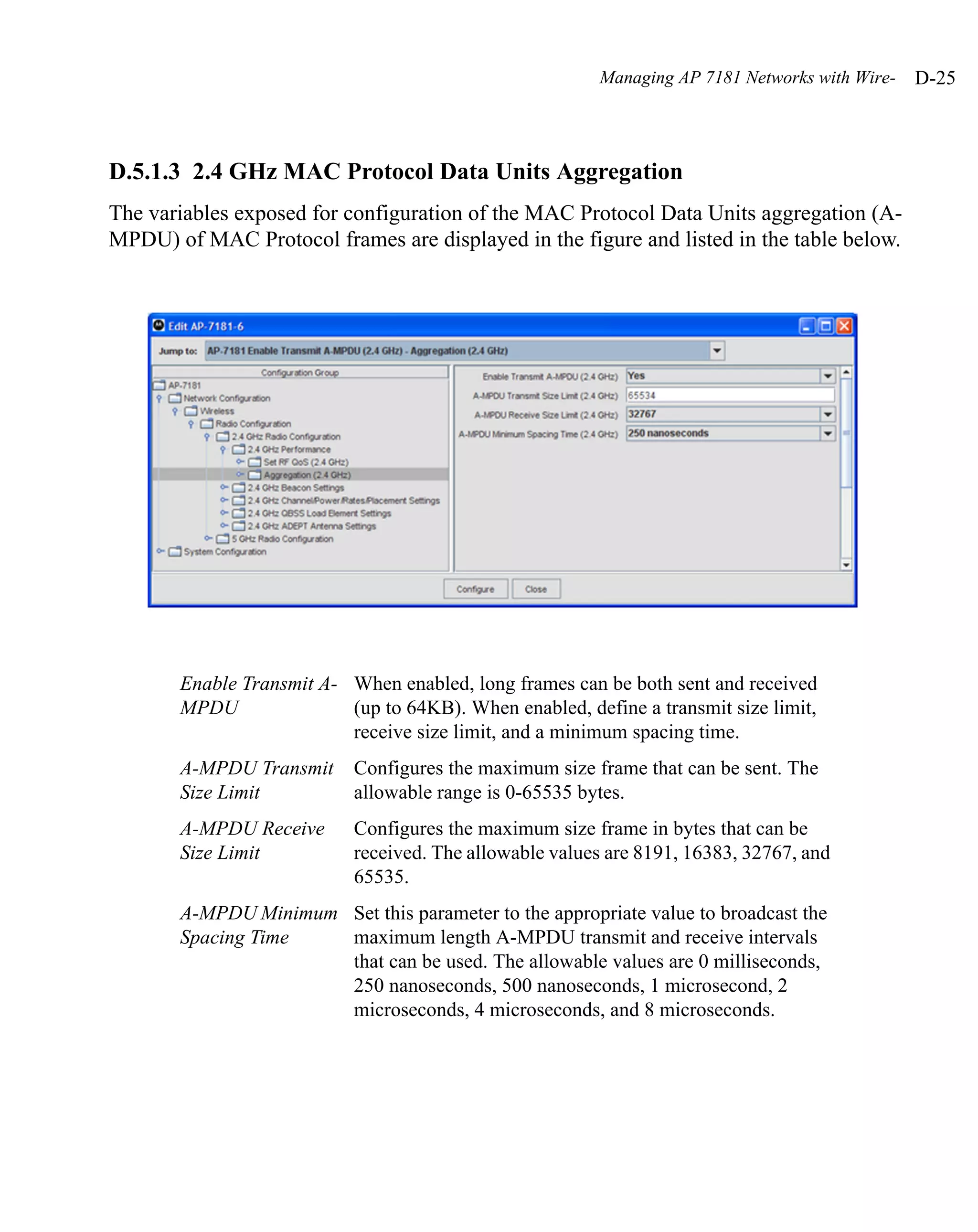
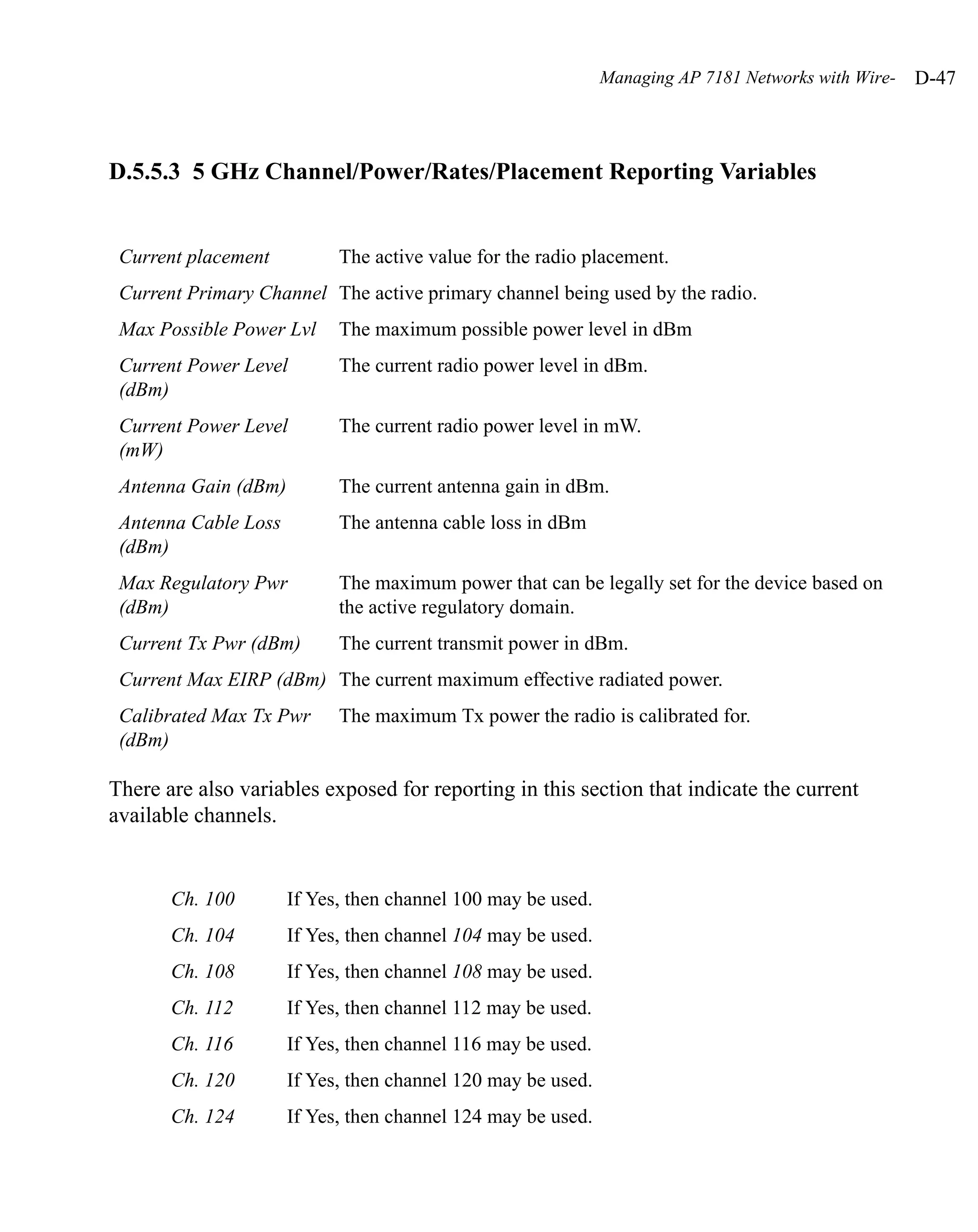
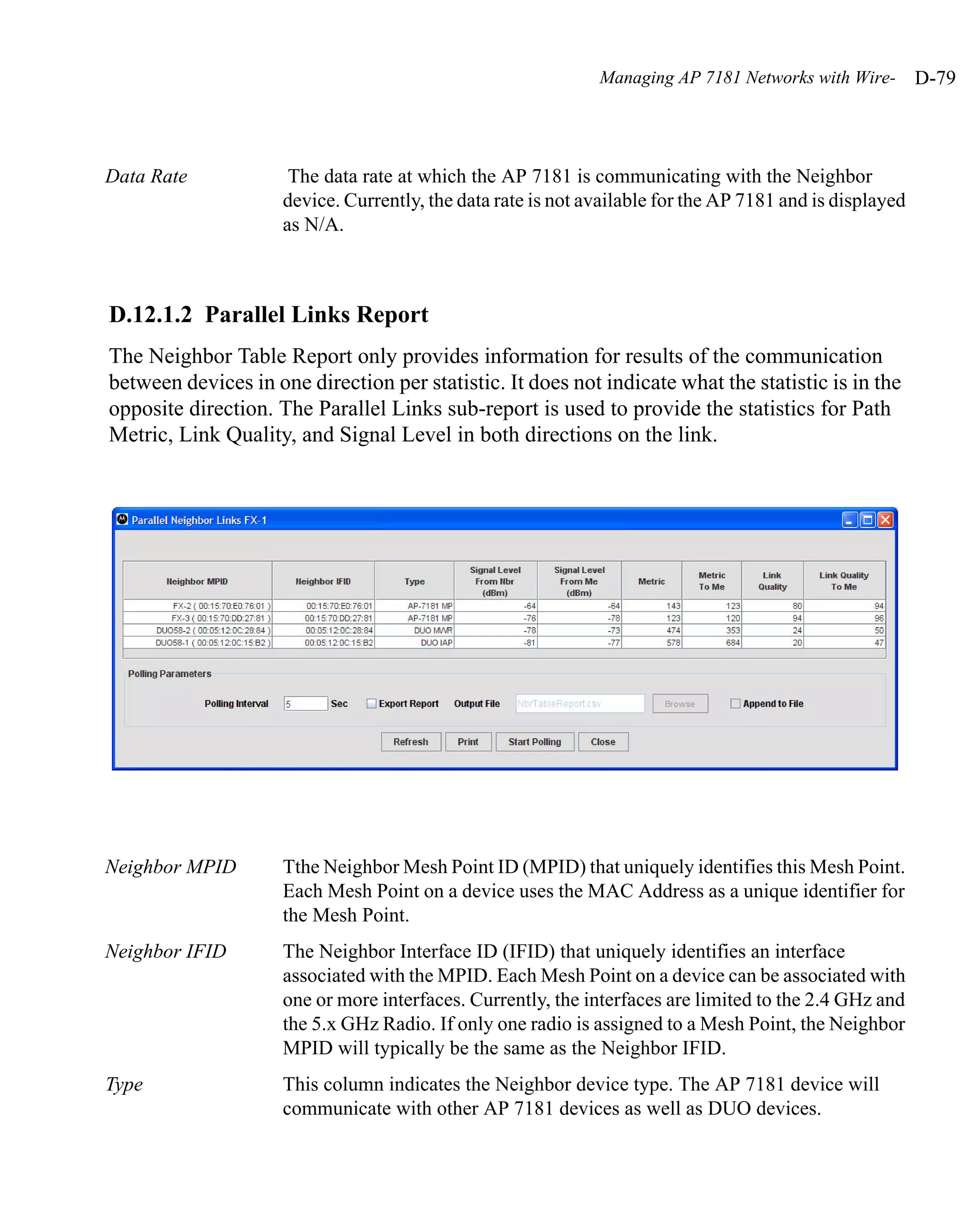
![Managing AP 7181 Networks with Wire- D-35
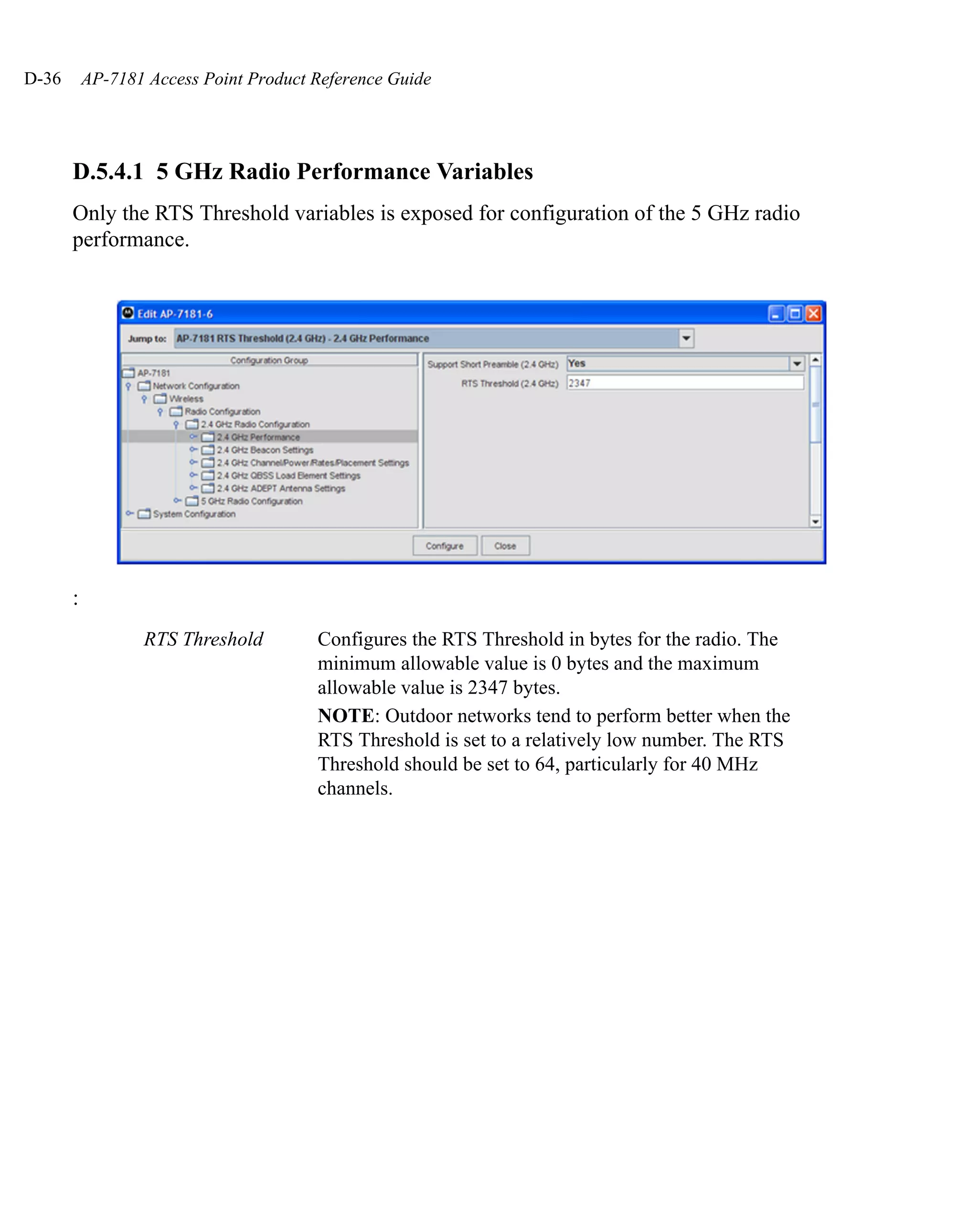
D.5.3 5 GHz Radio Configuration
The settings for the 5.x GHz Radio Configuration are shown in the Network Configuration
/ Radio Configuration / Radio2[802.11a/n] tree item in the AP 7181 web page
configuration. The enable/disable configuration and some of the reporting items from the
Network Configuration / Radio Configuration tree item in the AP 7181 web page
configuration are also supported.
D.5.4 5 GHz Configurable Variables
Only one variable is exposed to enable the 5 GHz radio:
Radio Enable This setting enables or disables the 5 GHz radio. When
disabled, the radio will not transmit or receive.](https://image.slidesharecdn.com/ap7181productreferenceguide-120807015046-phpapp02/75/Ap7181-product-referenceguide-521-2048.jpg)
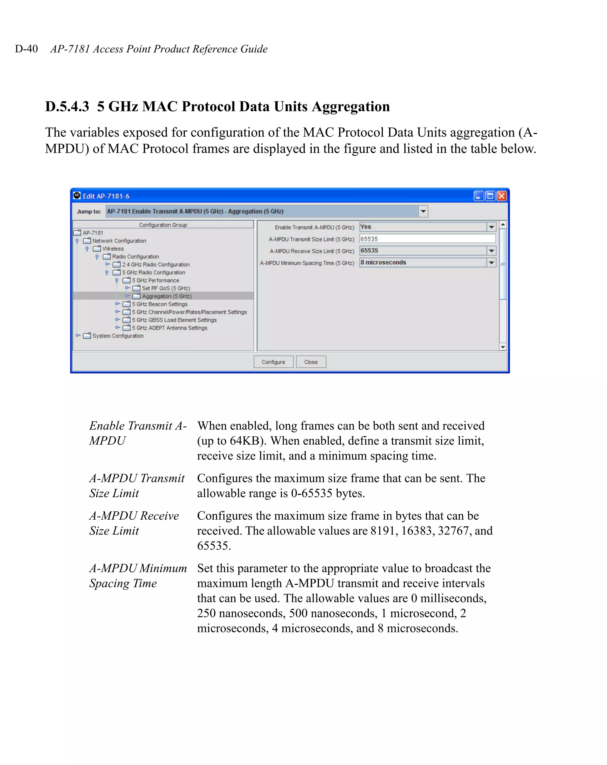
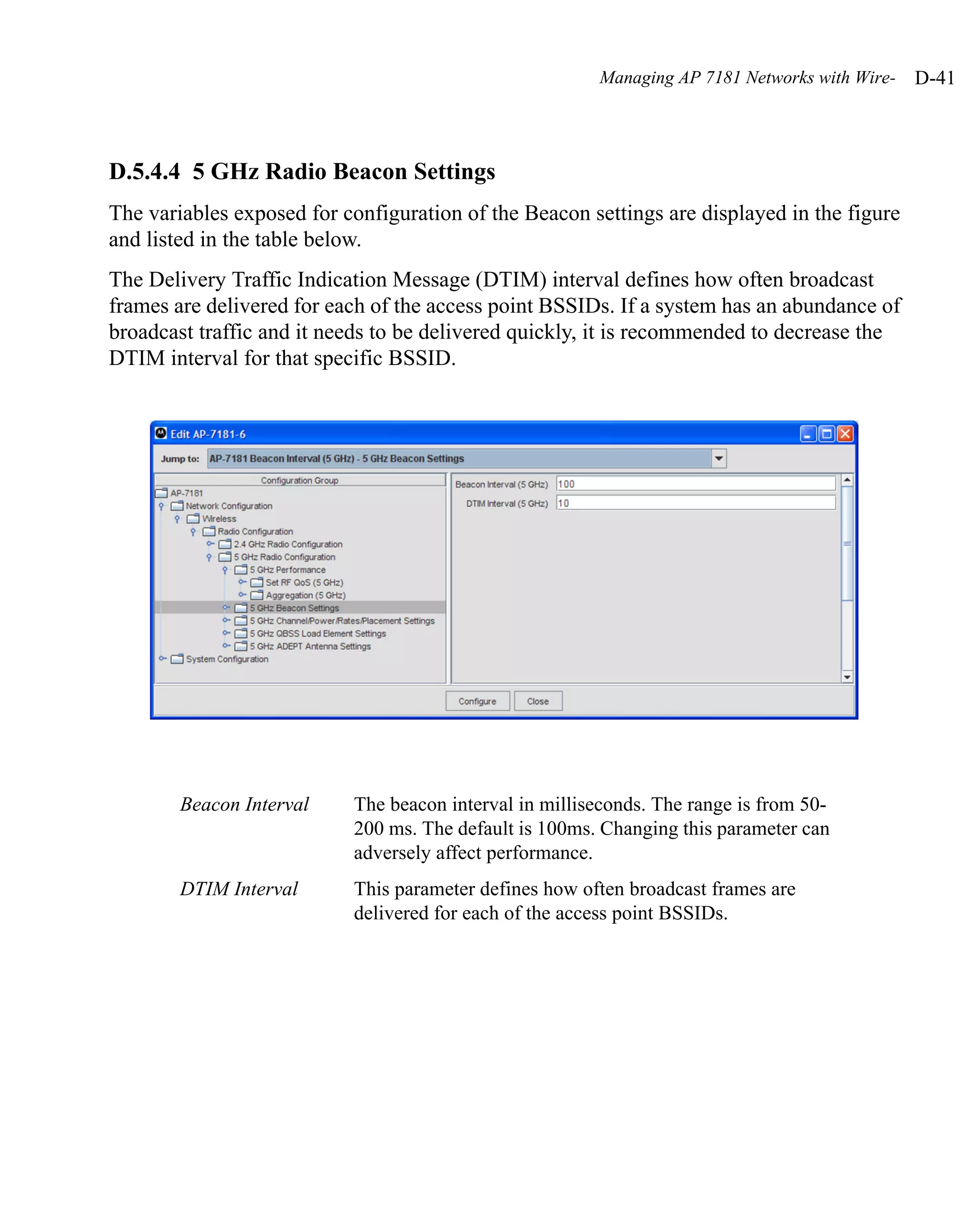
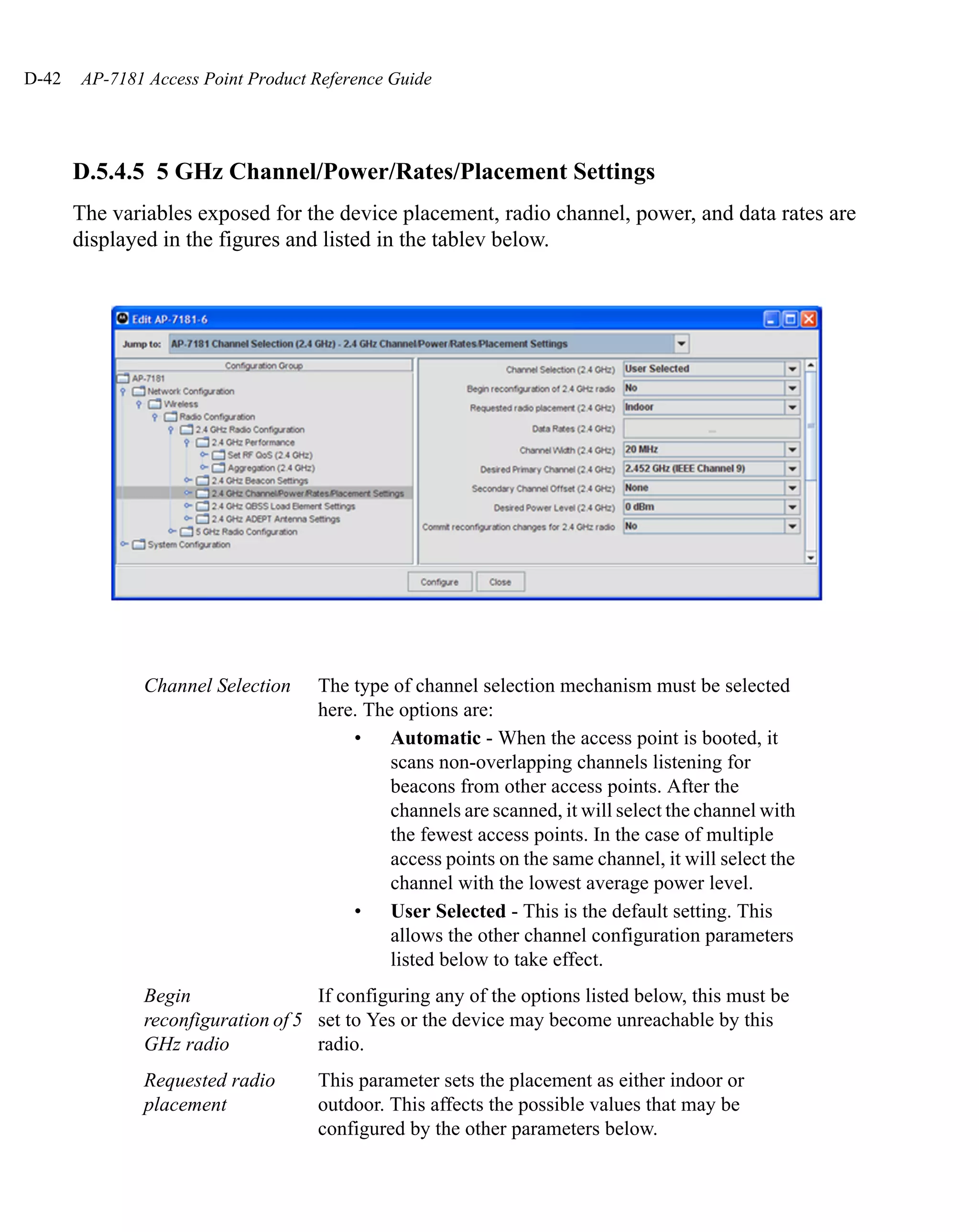
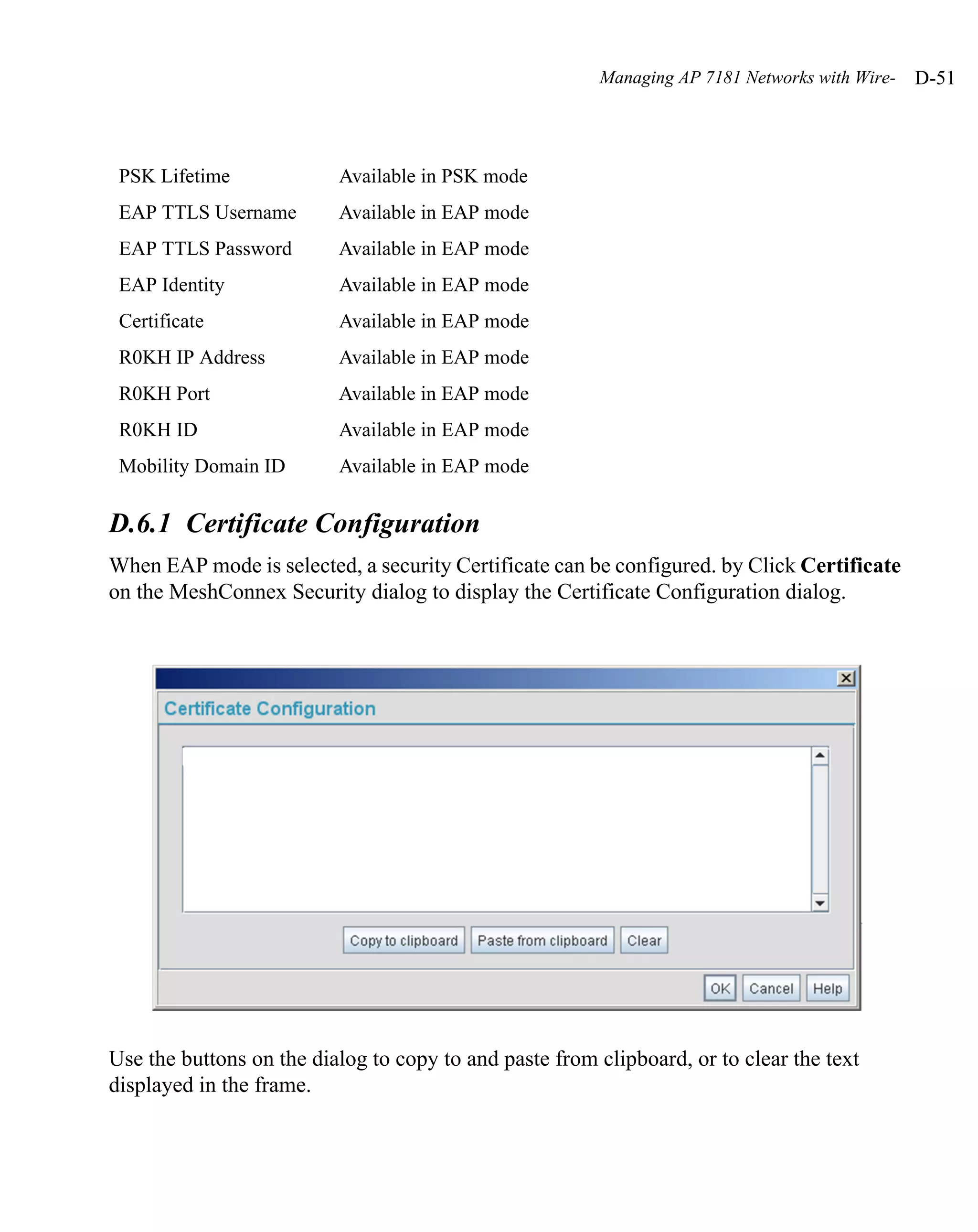
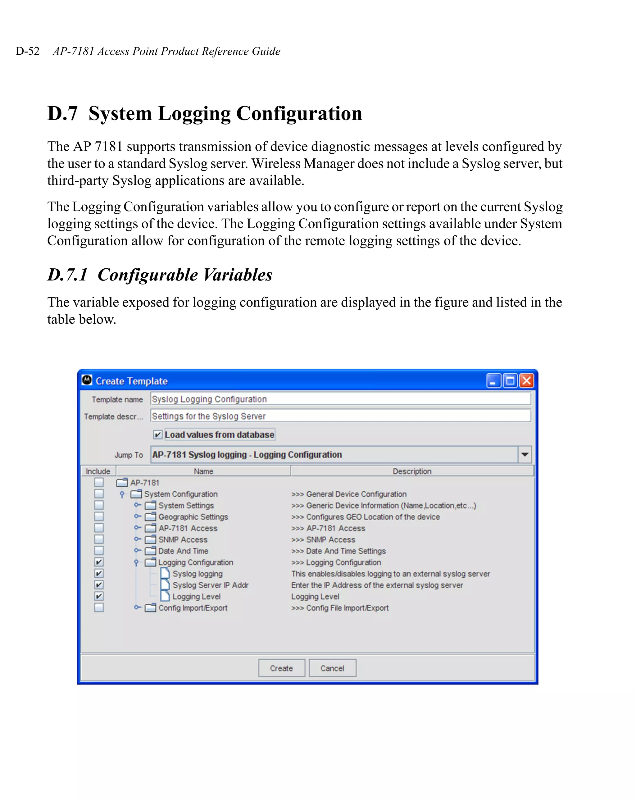
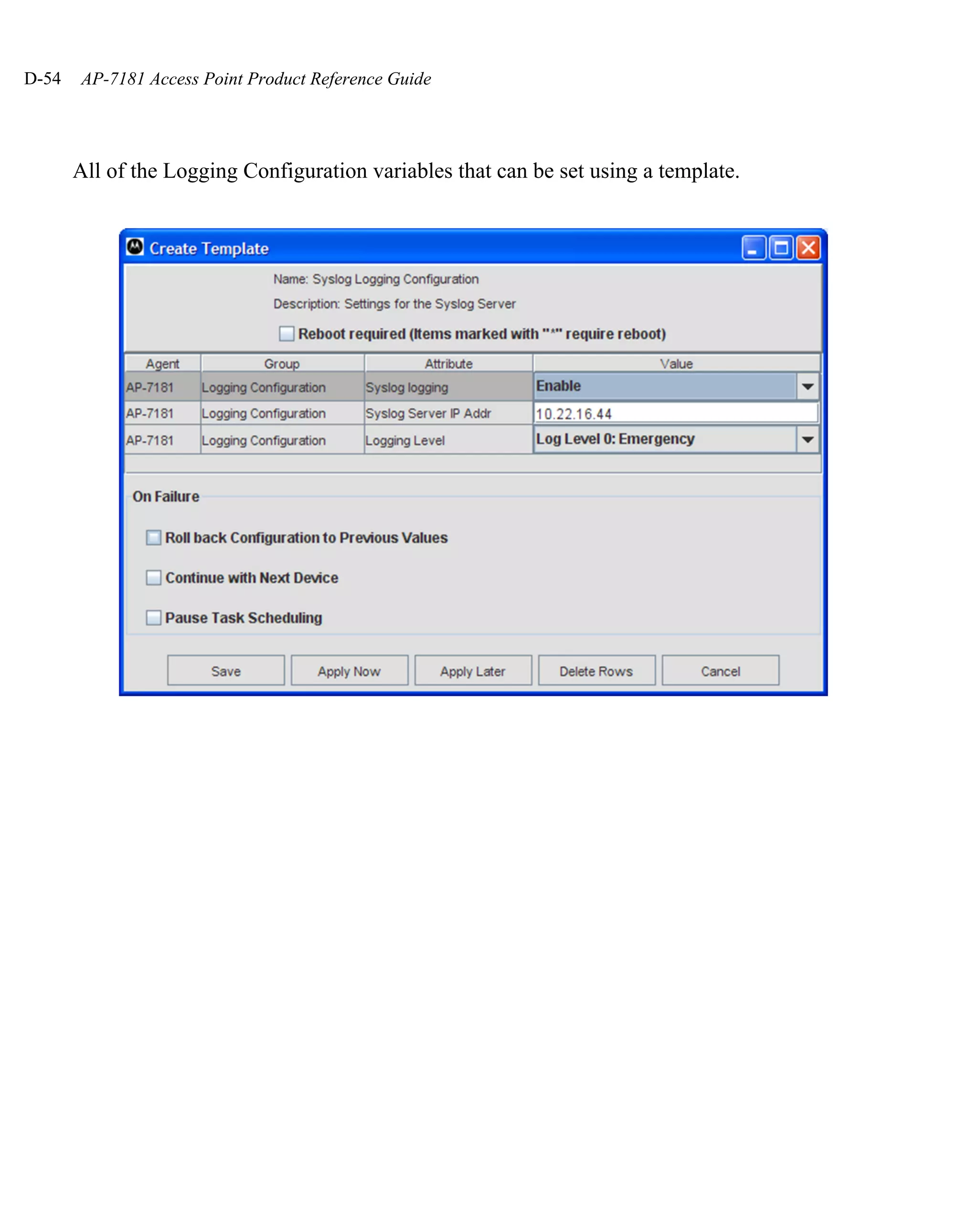
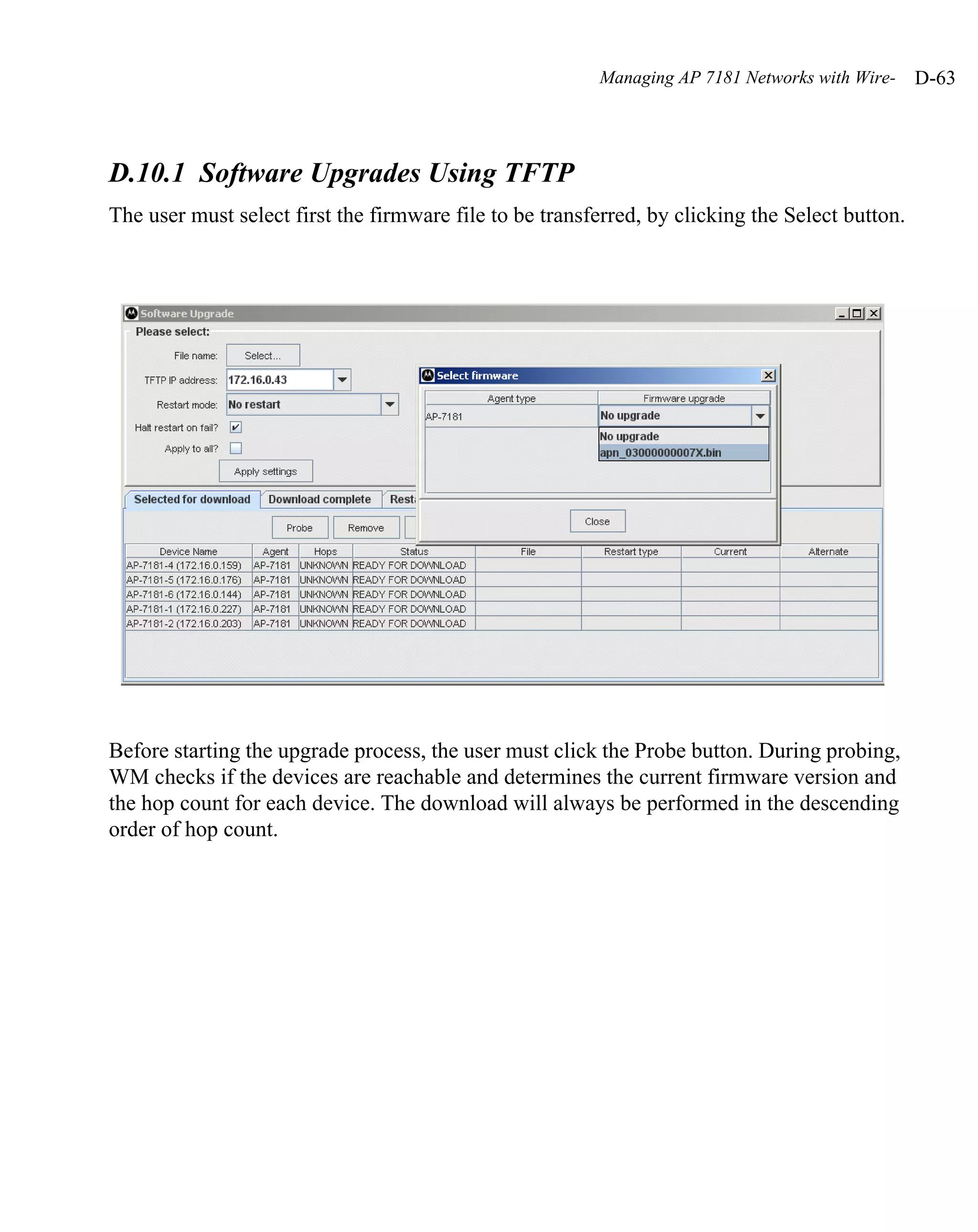
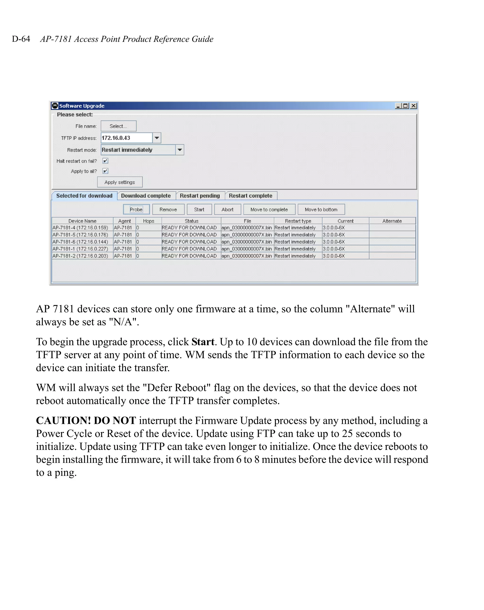
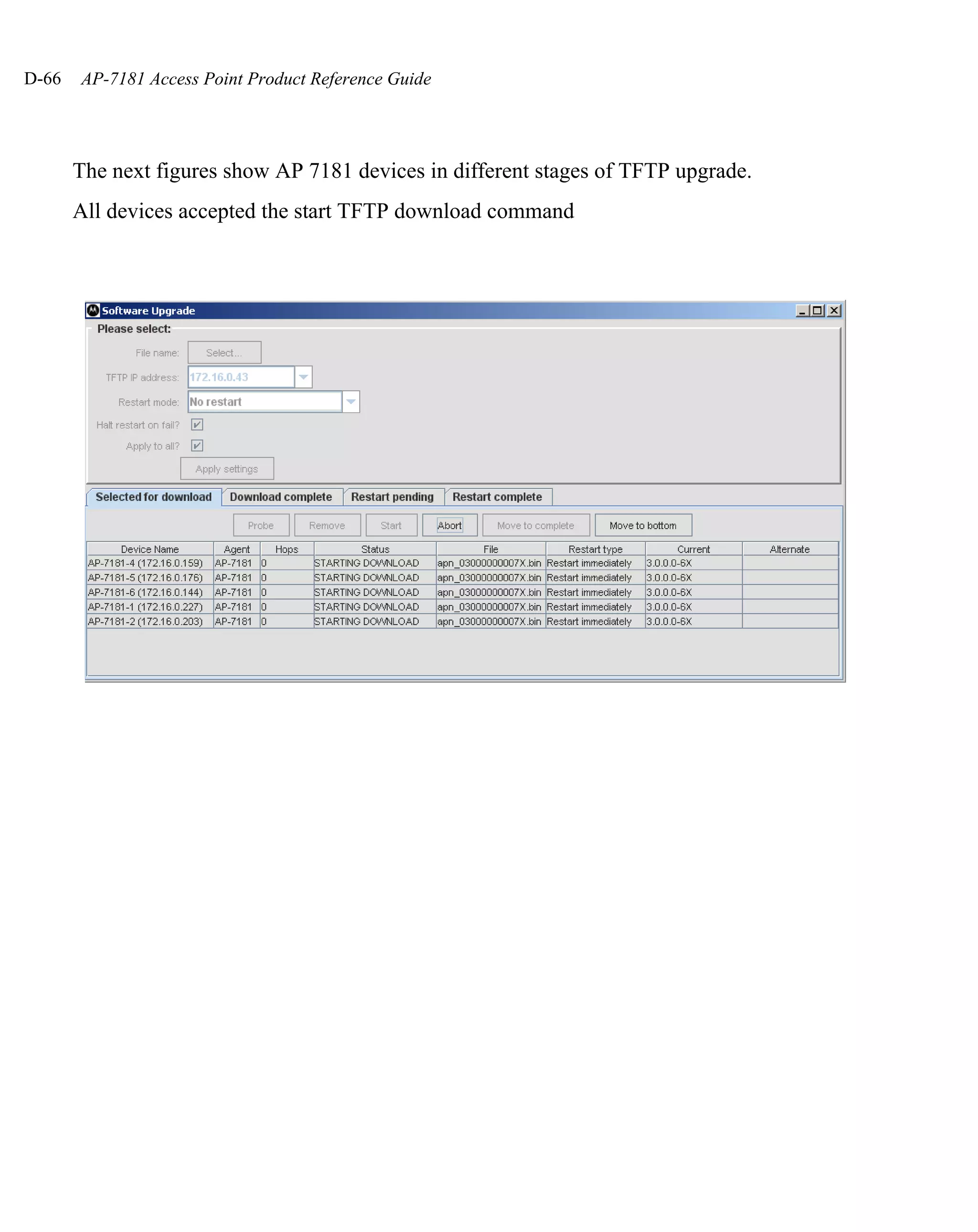
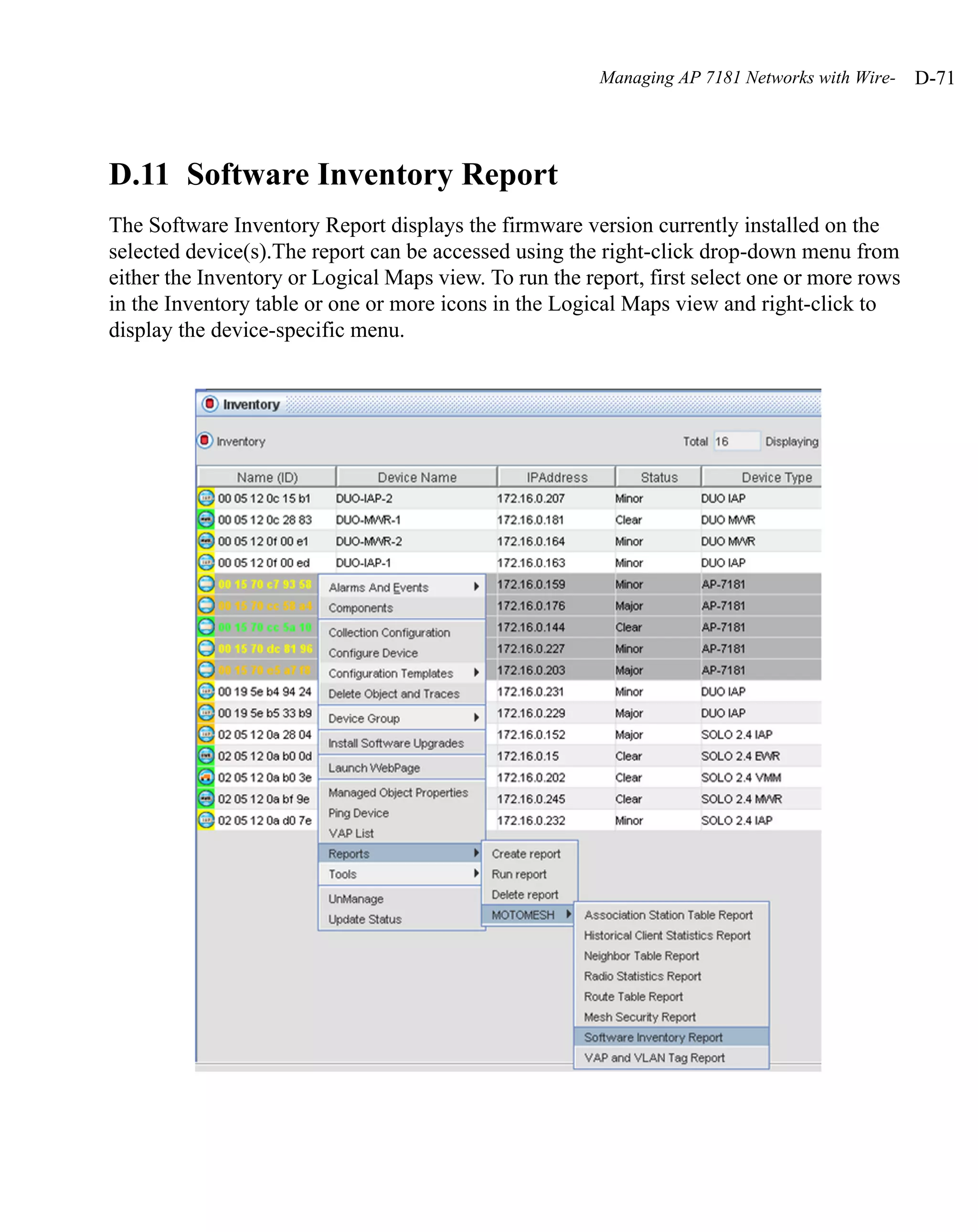
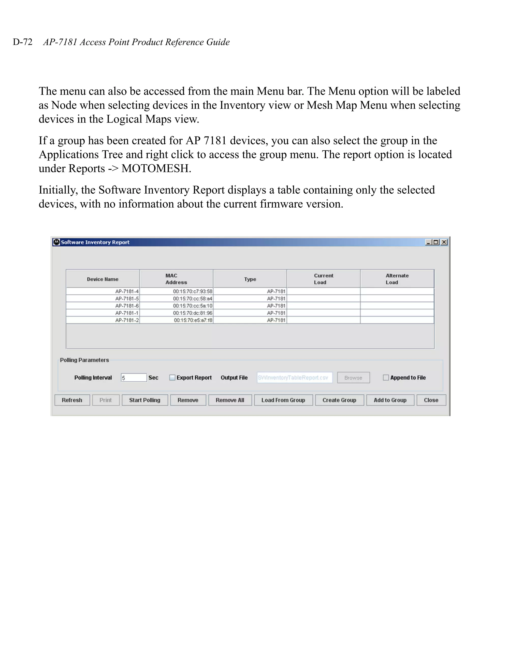
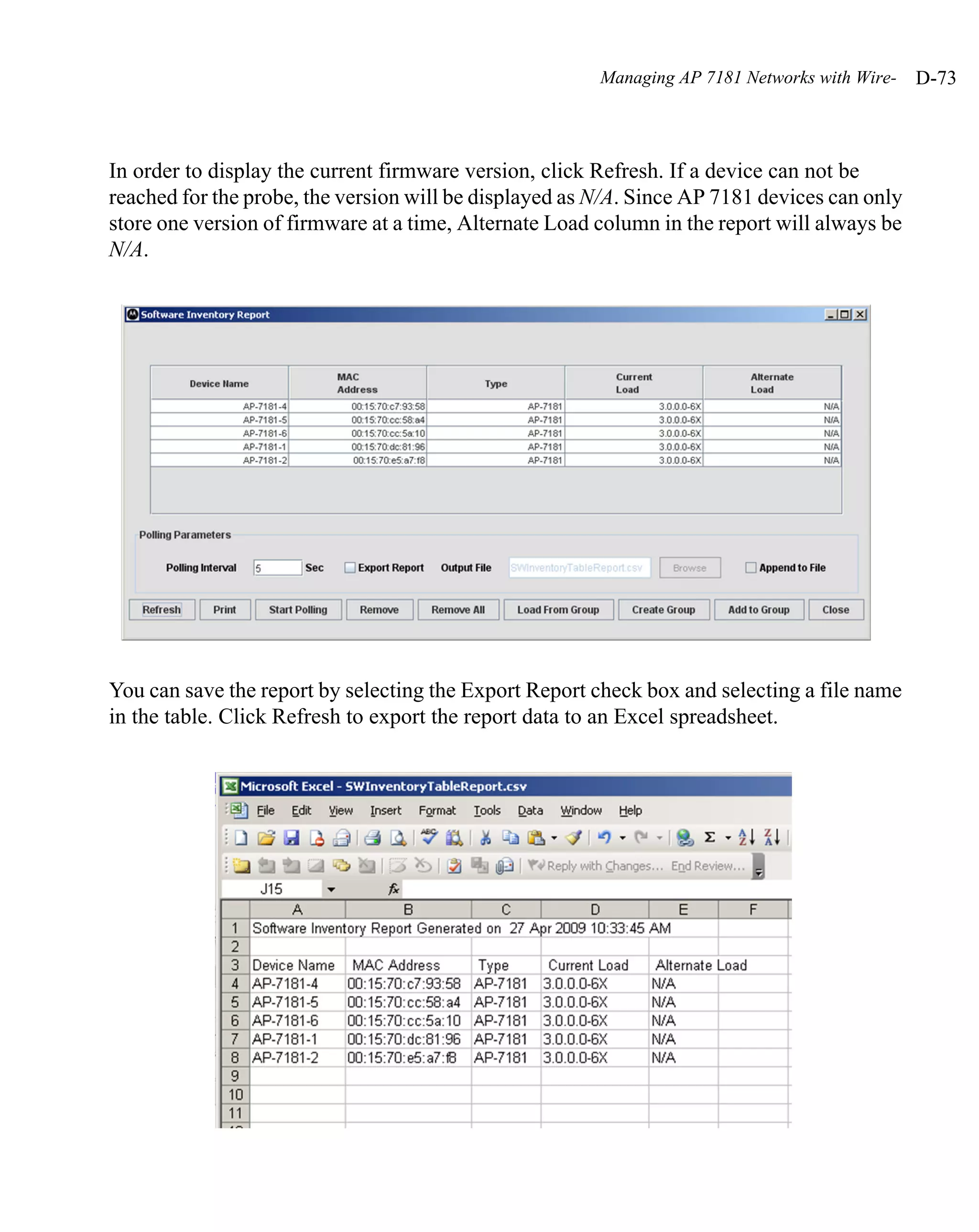
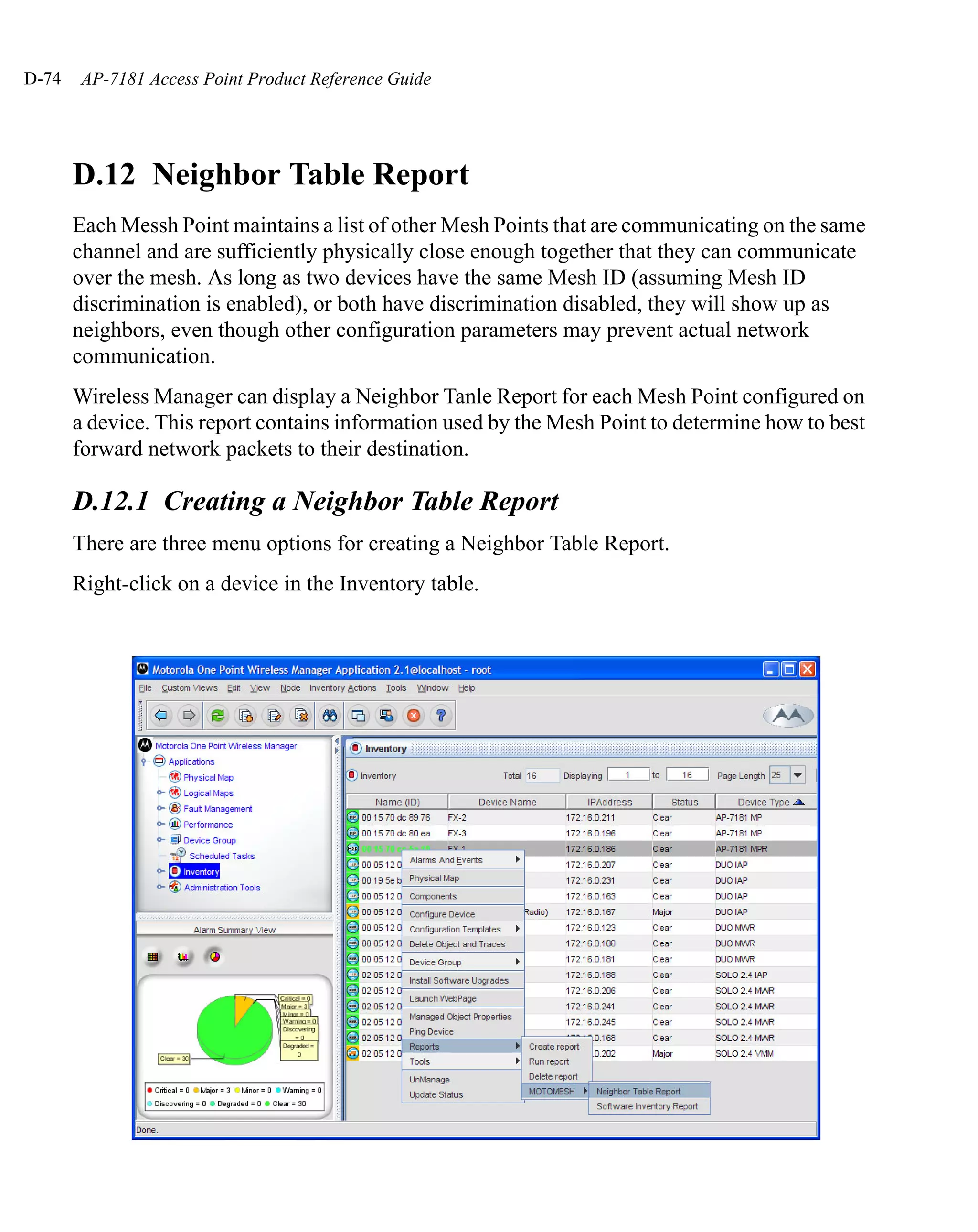
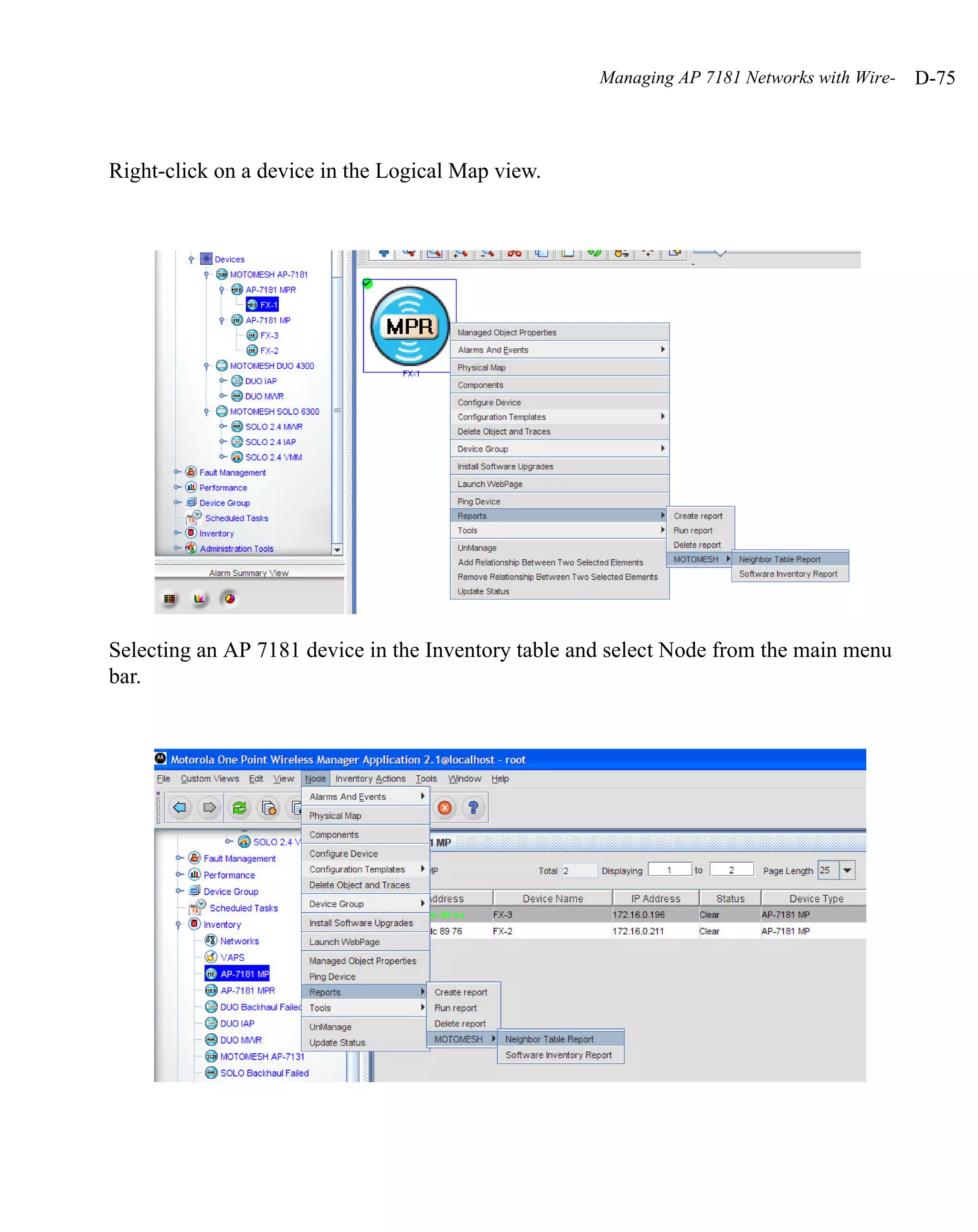


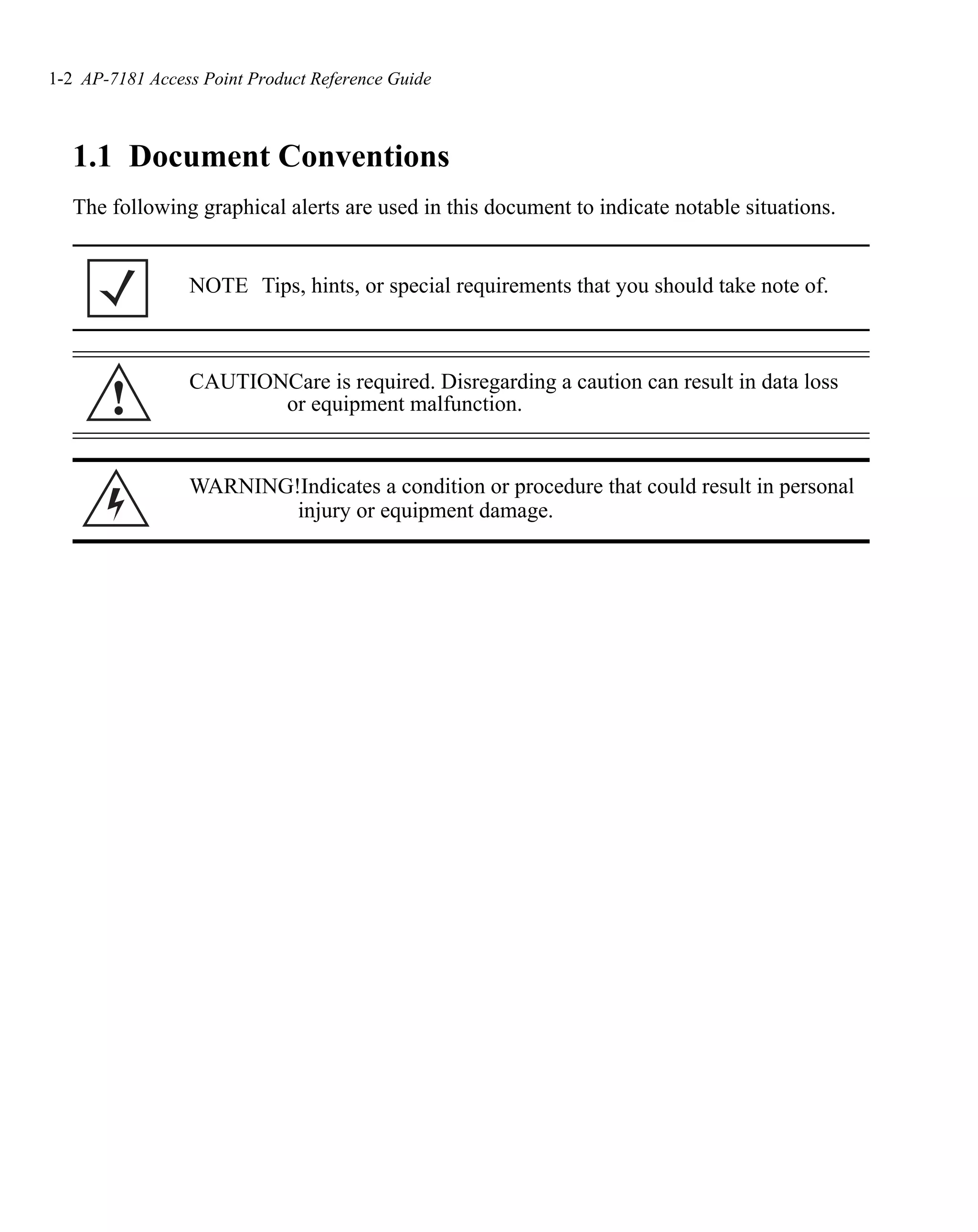
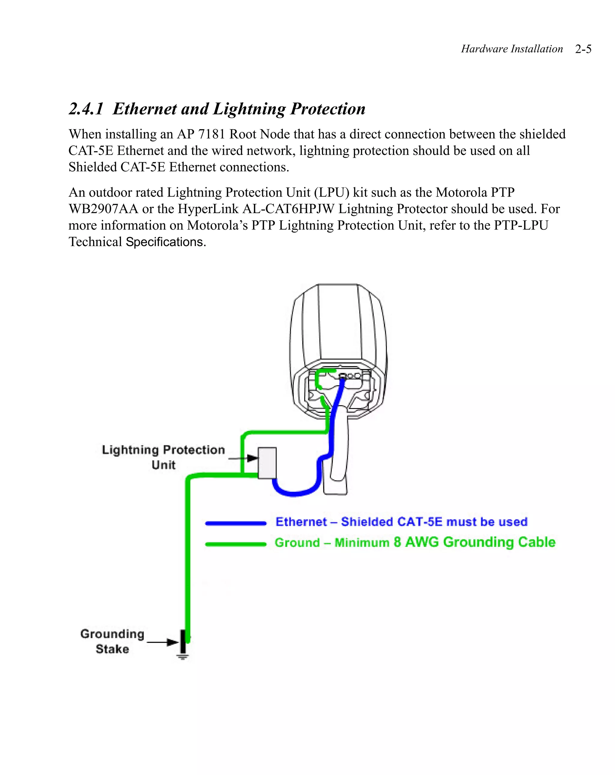
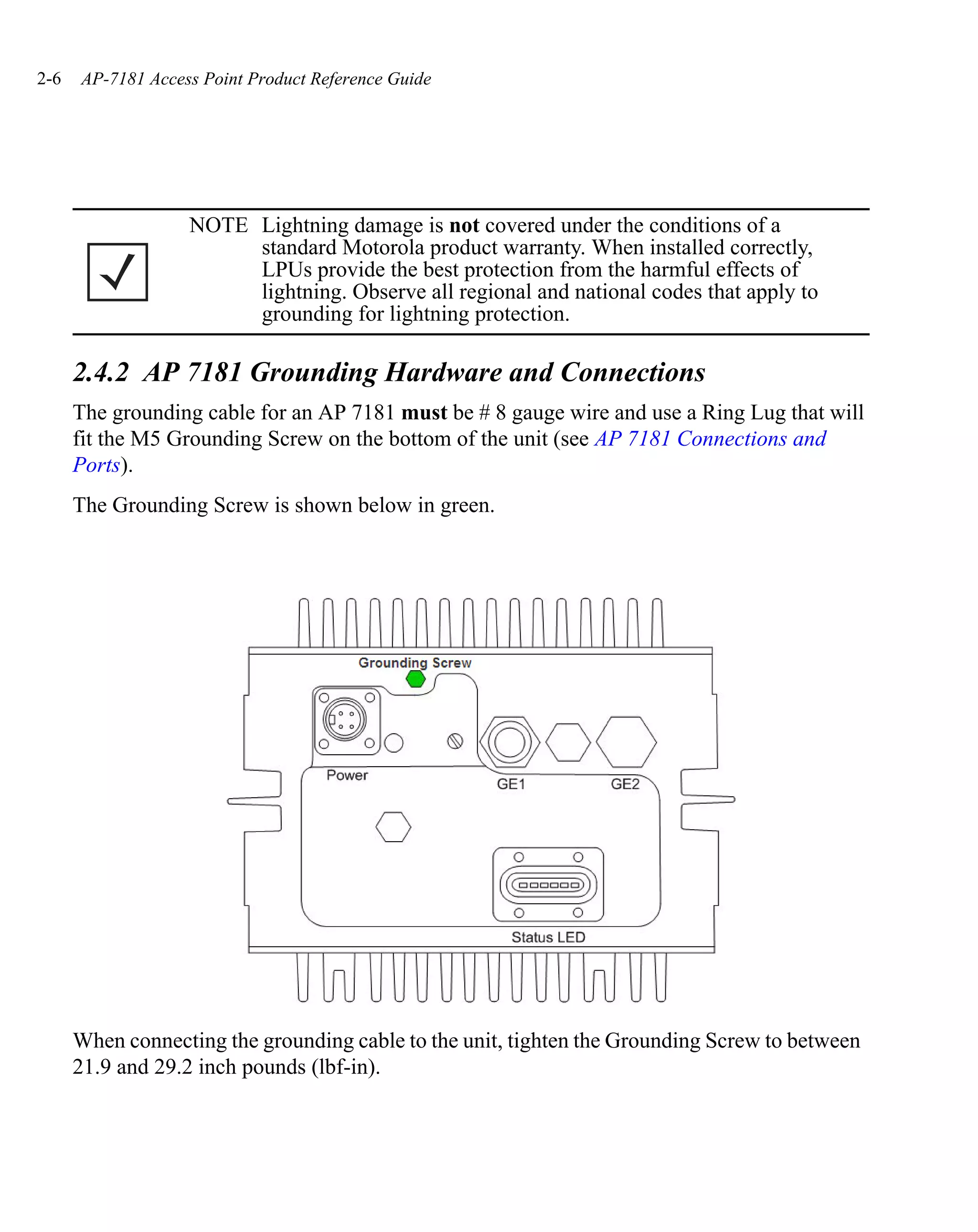
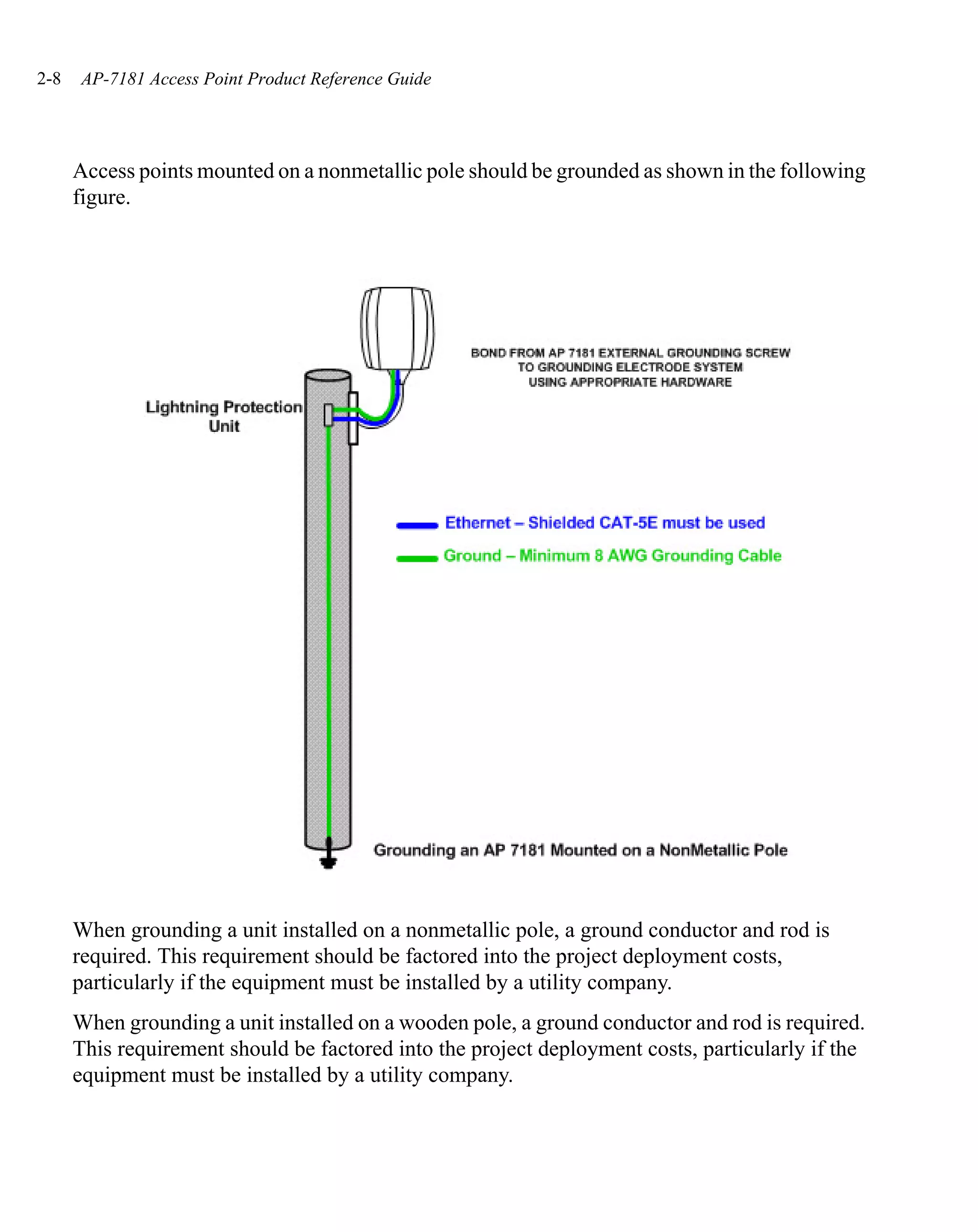
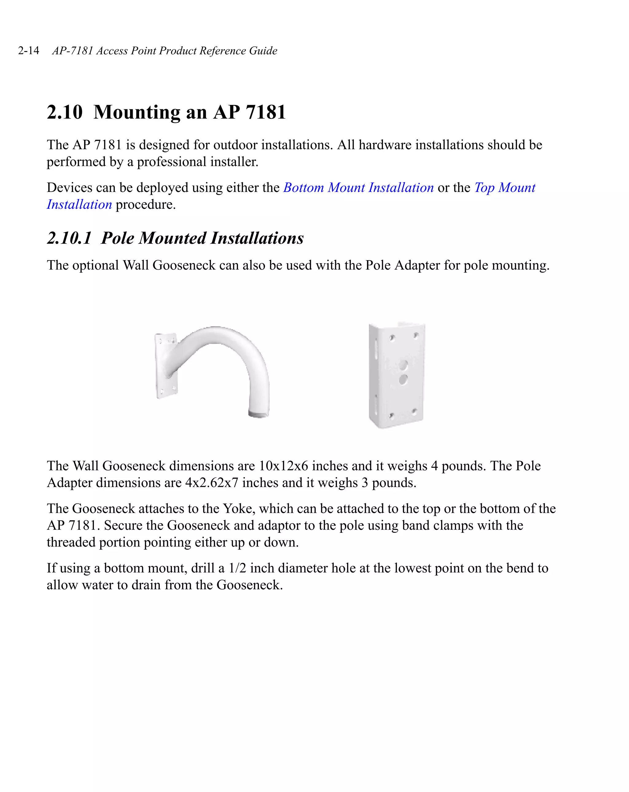
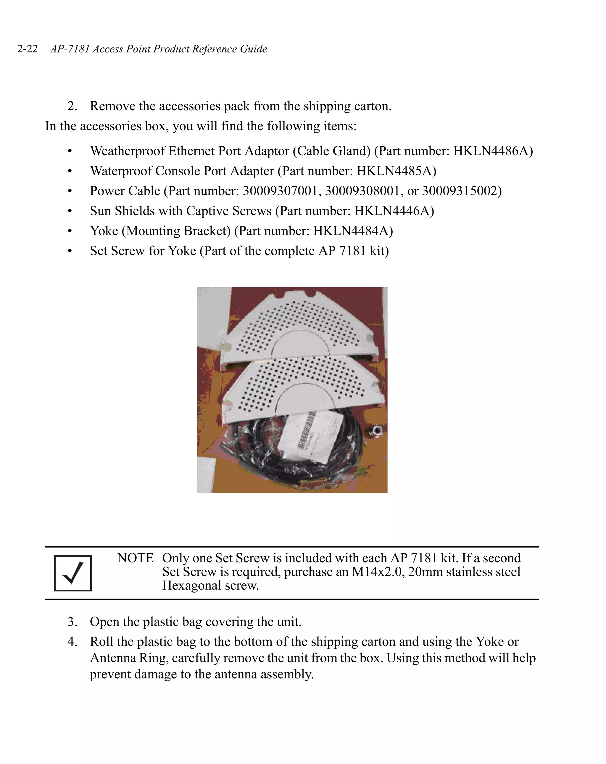
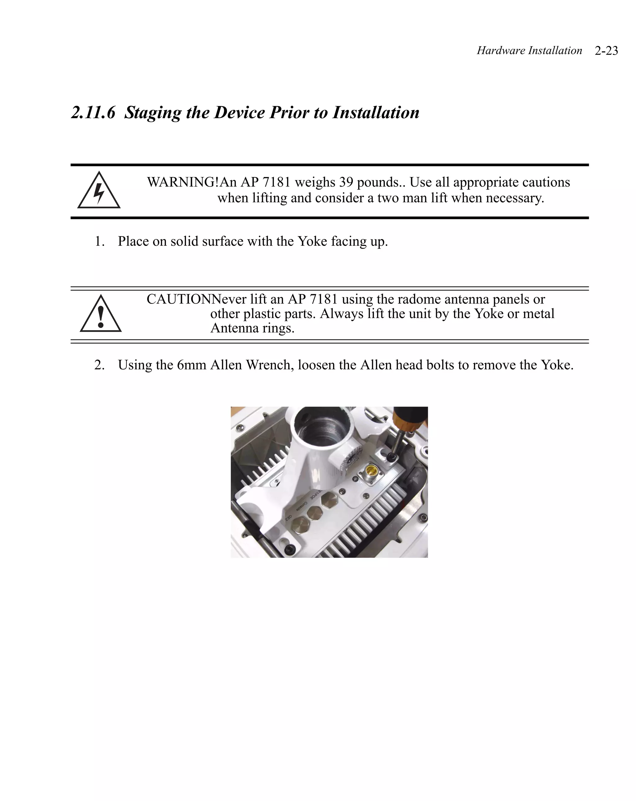
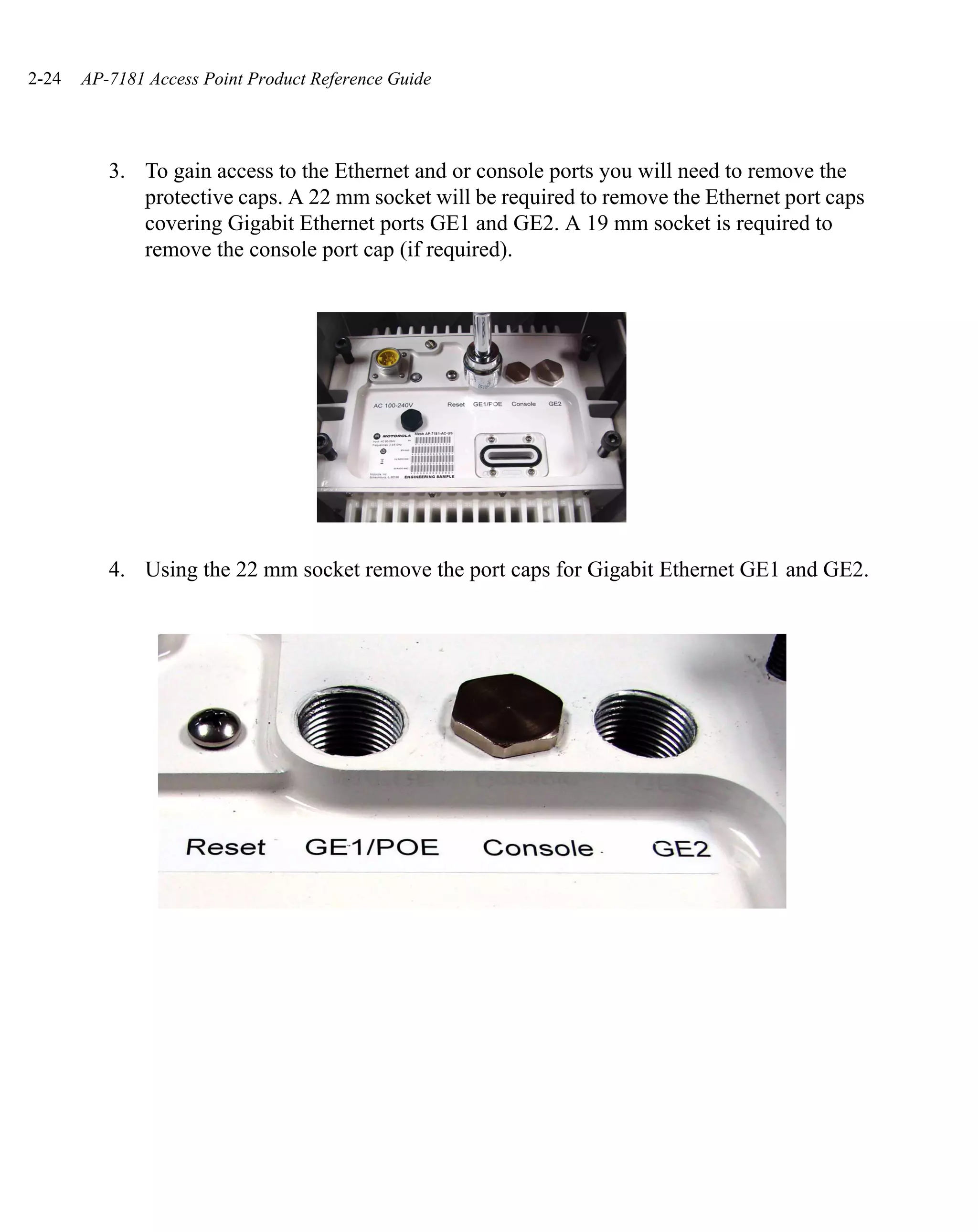
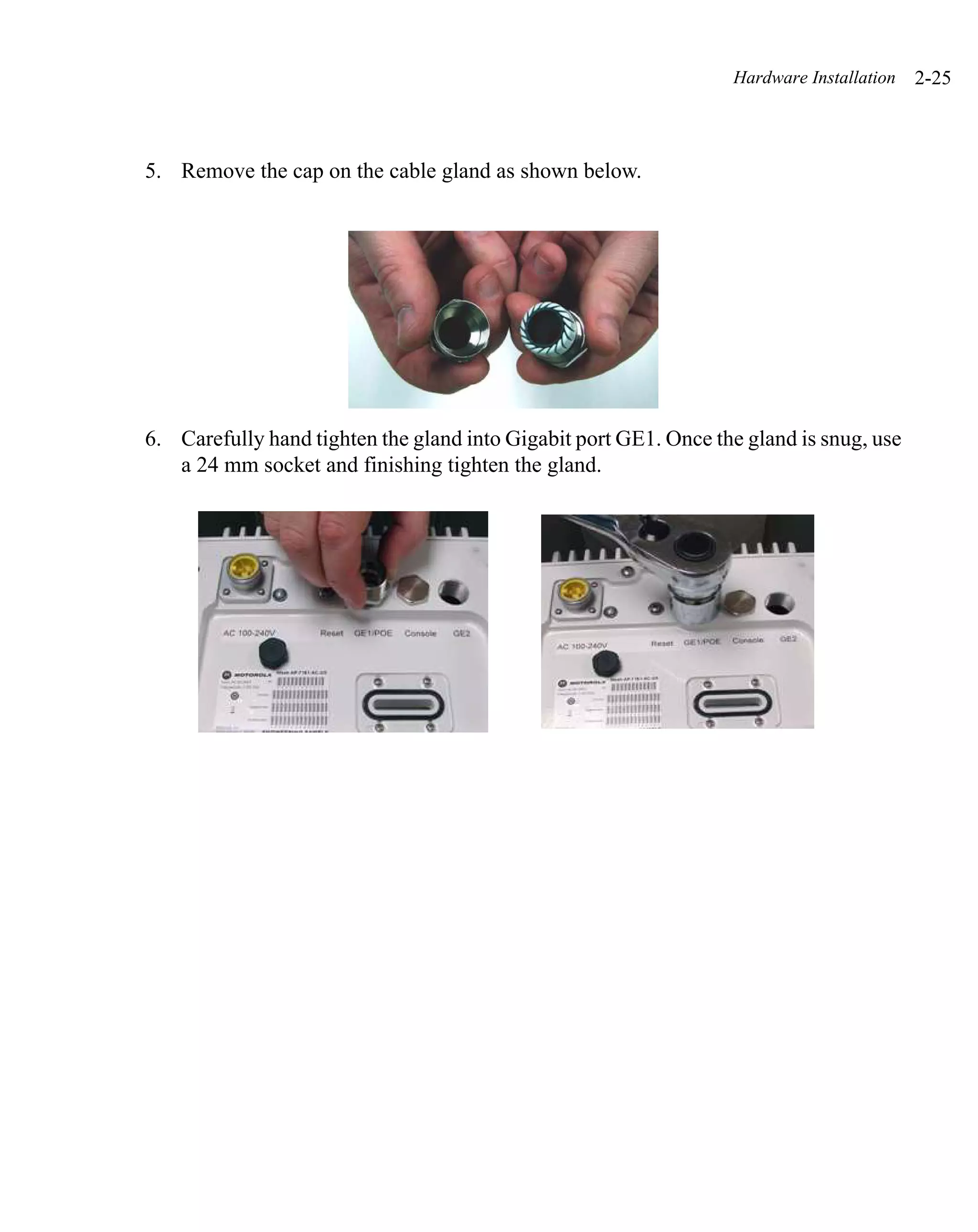
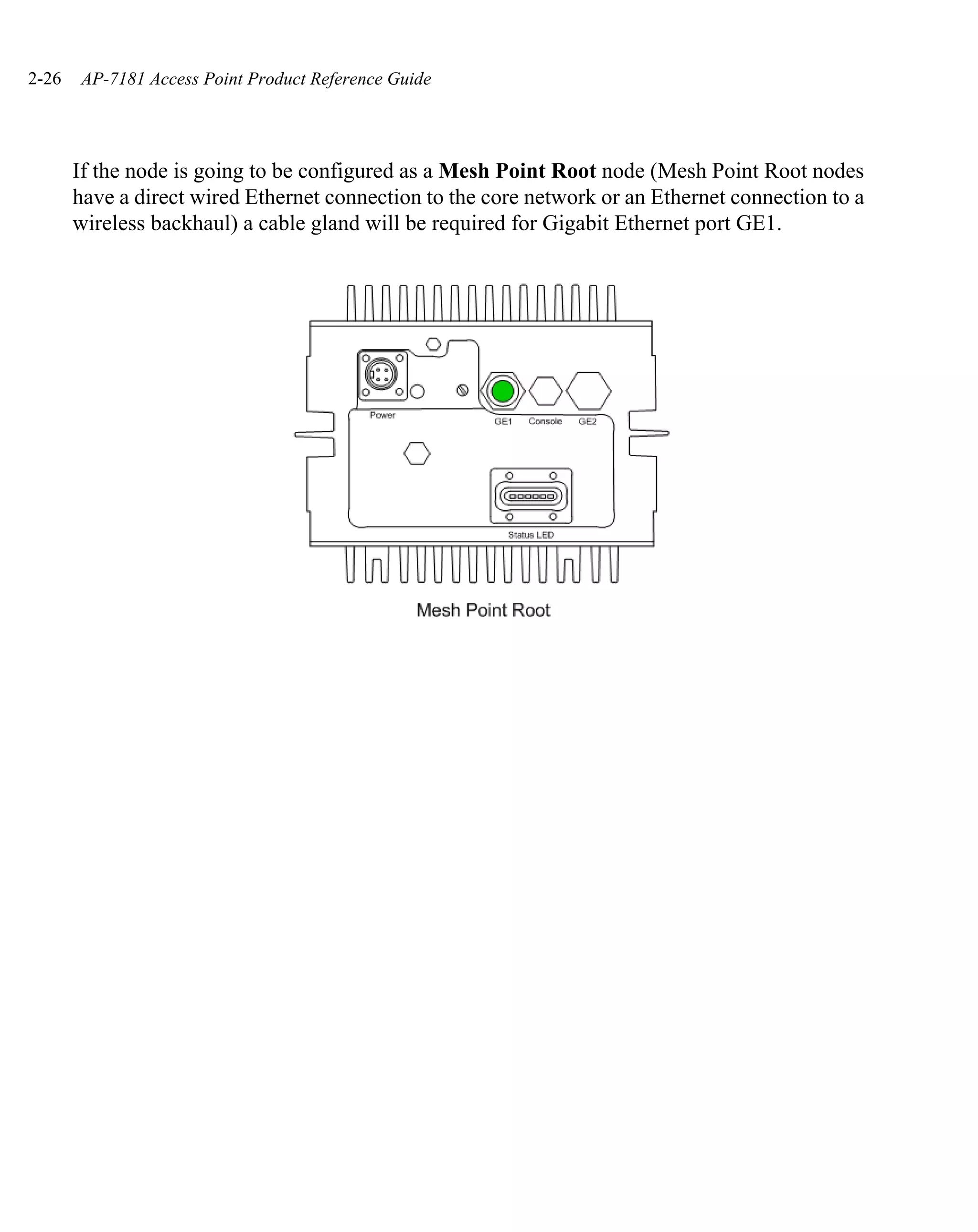
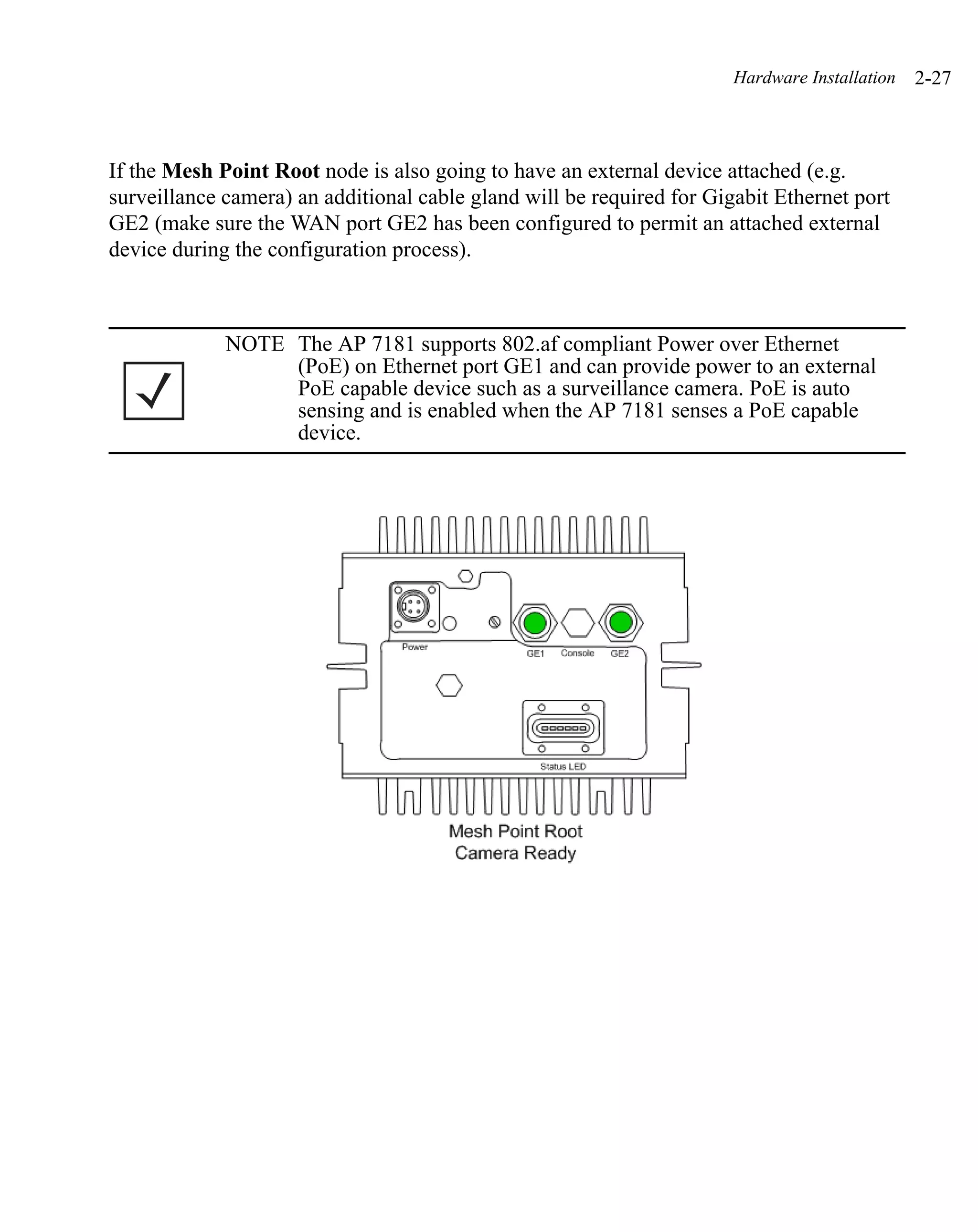
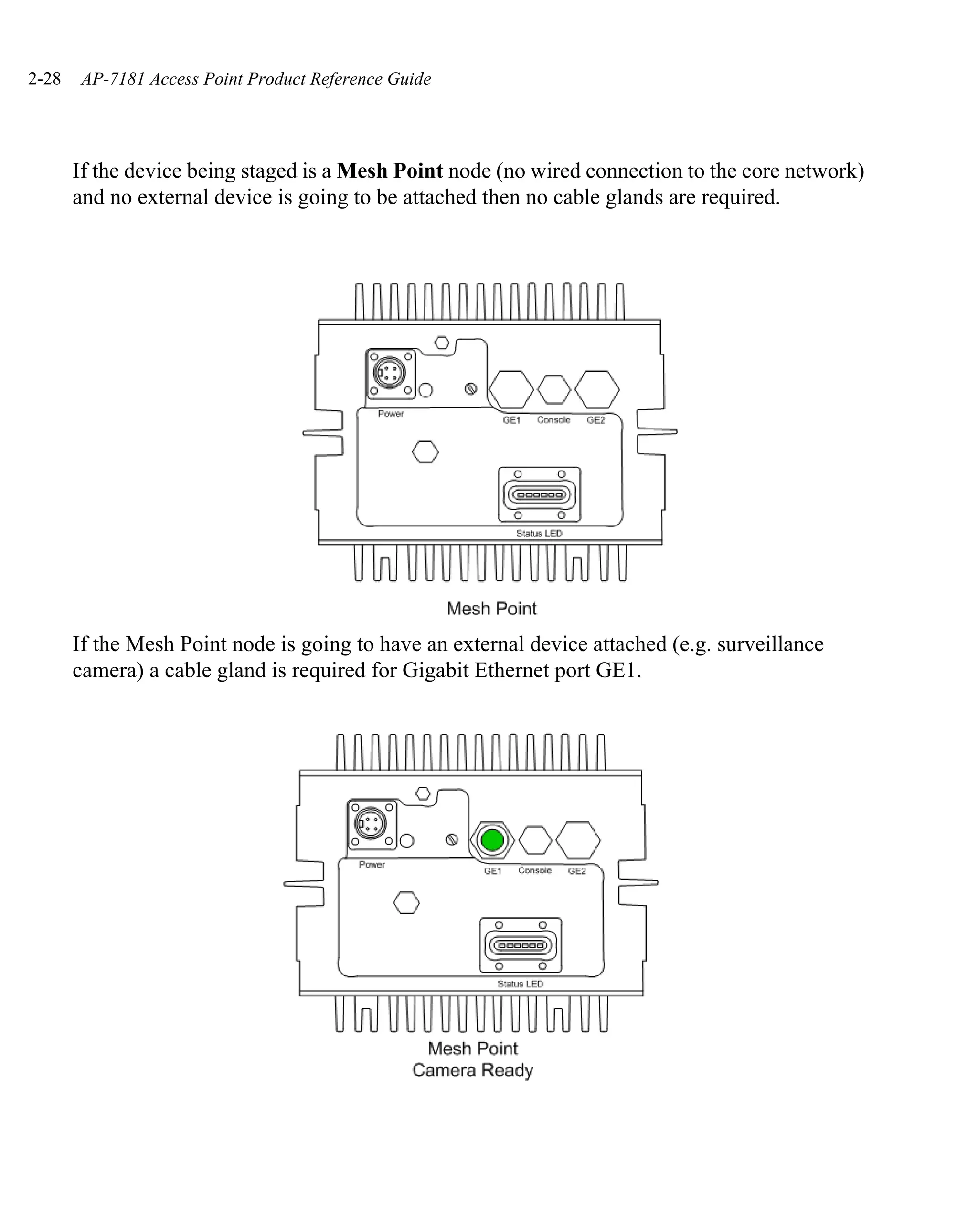
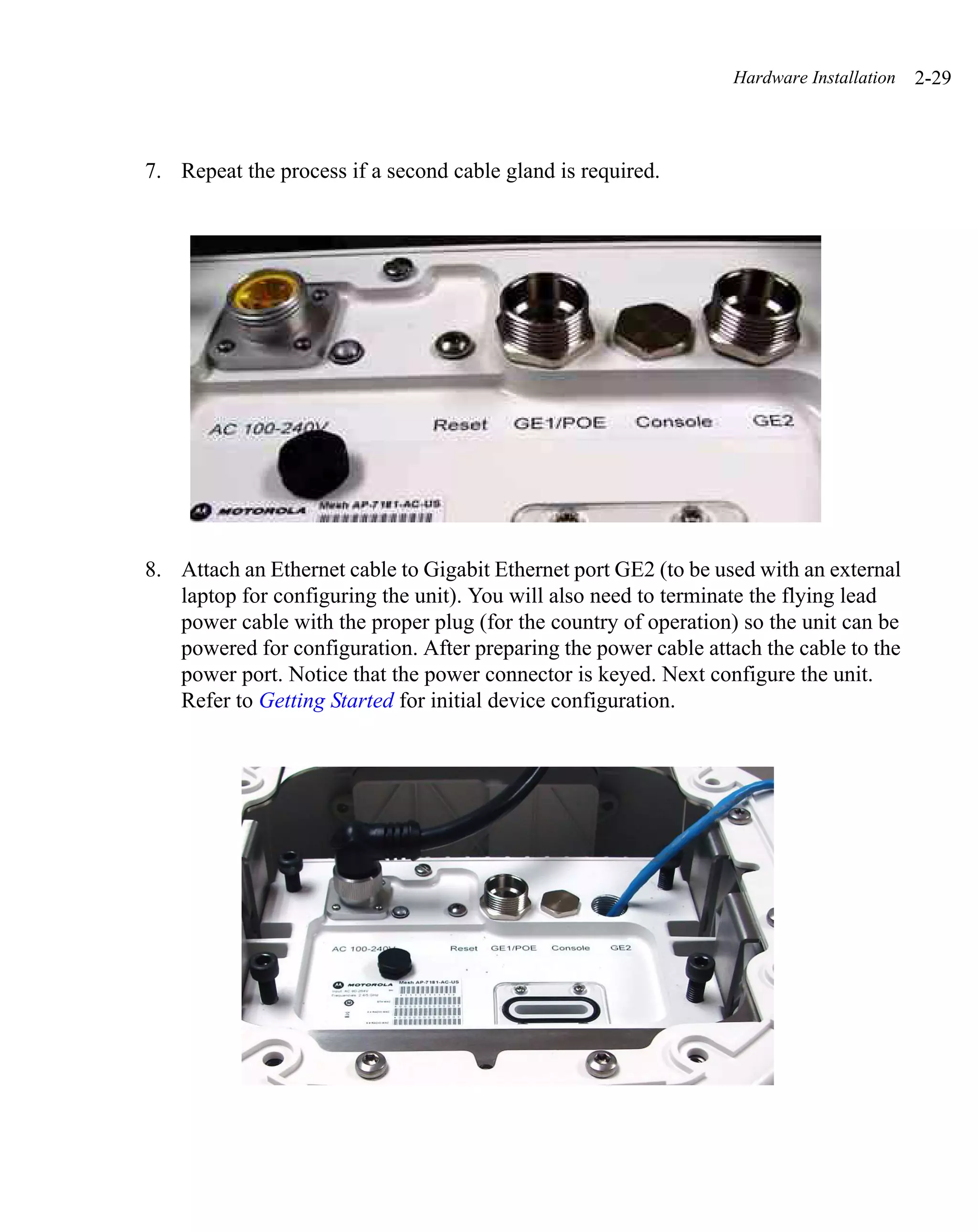
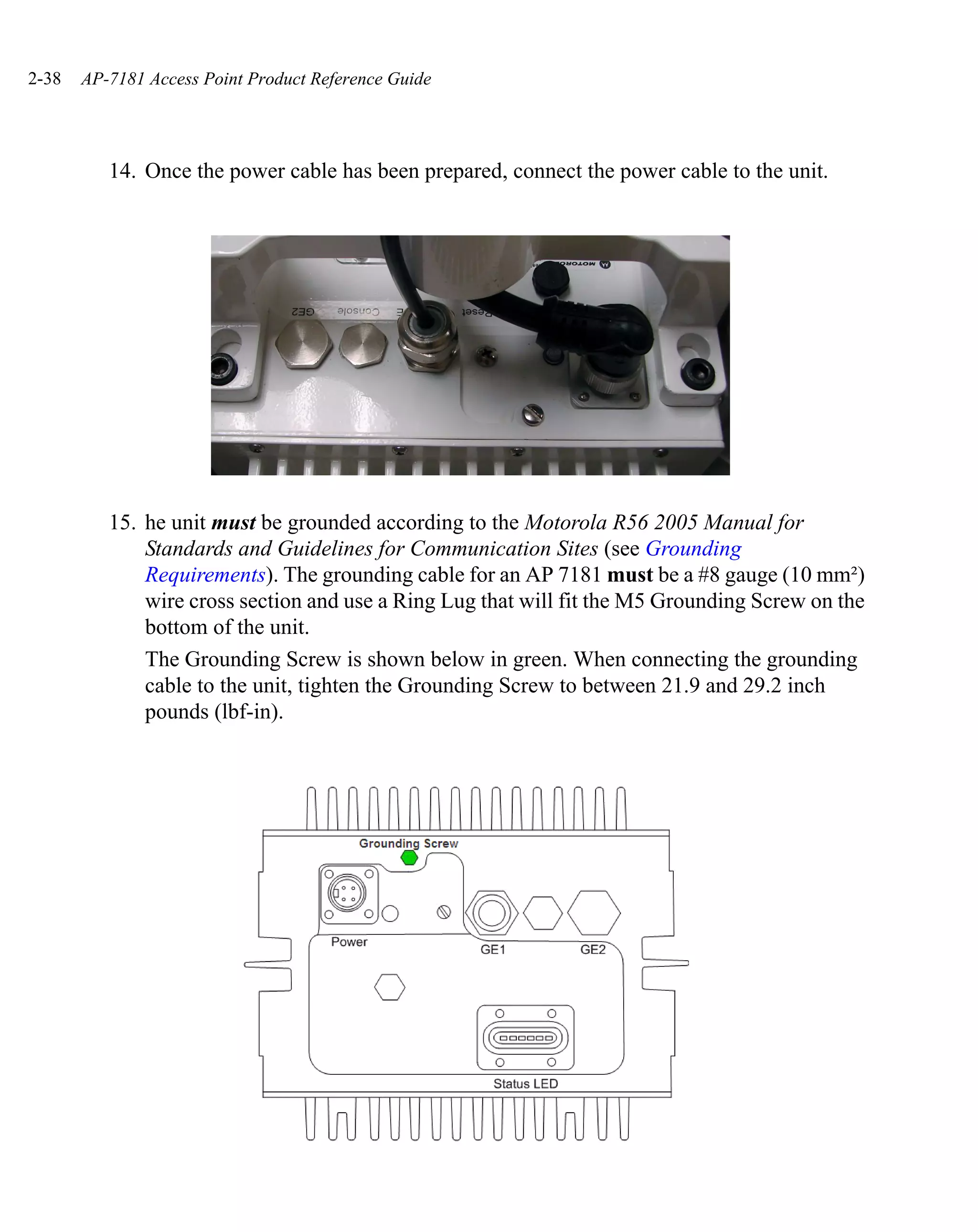
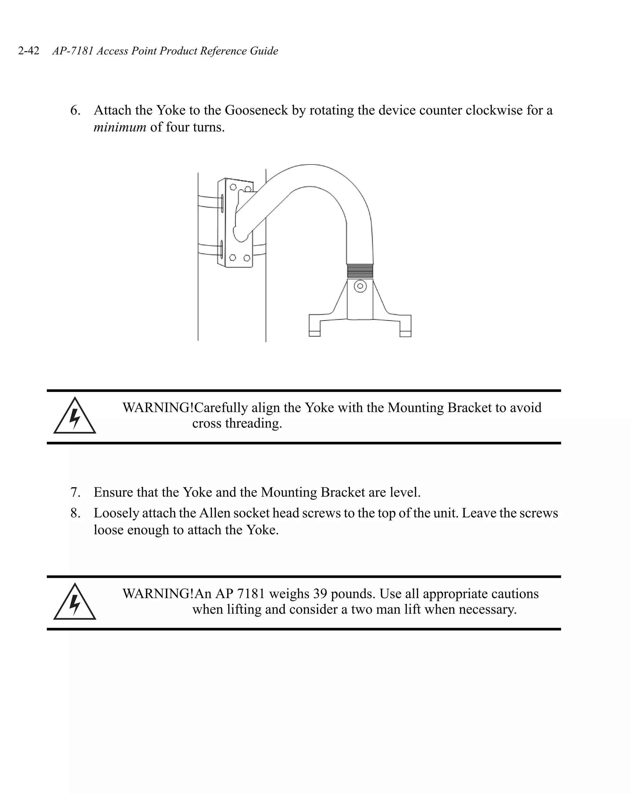
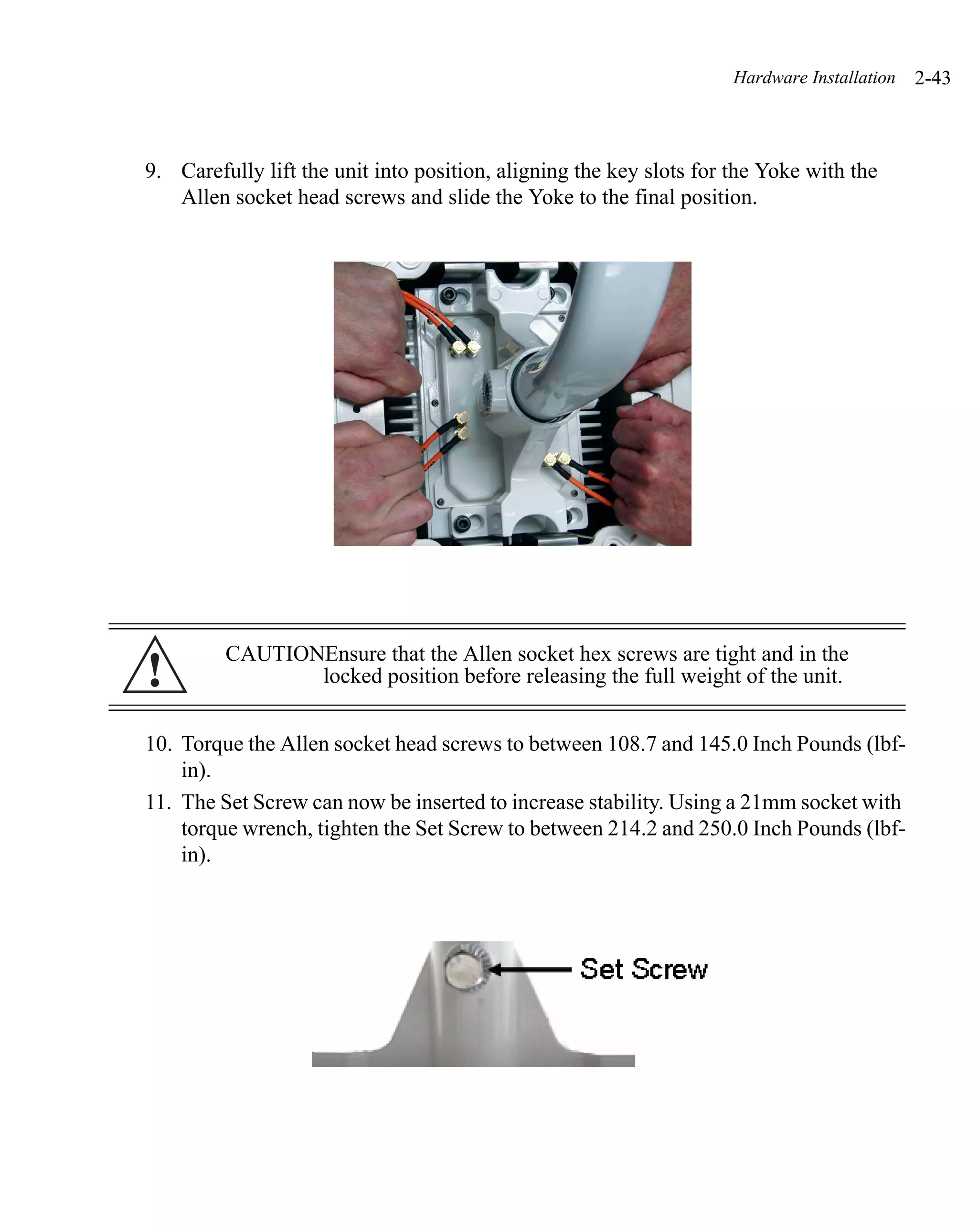
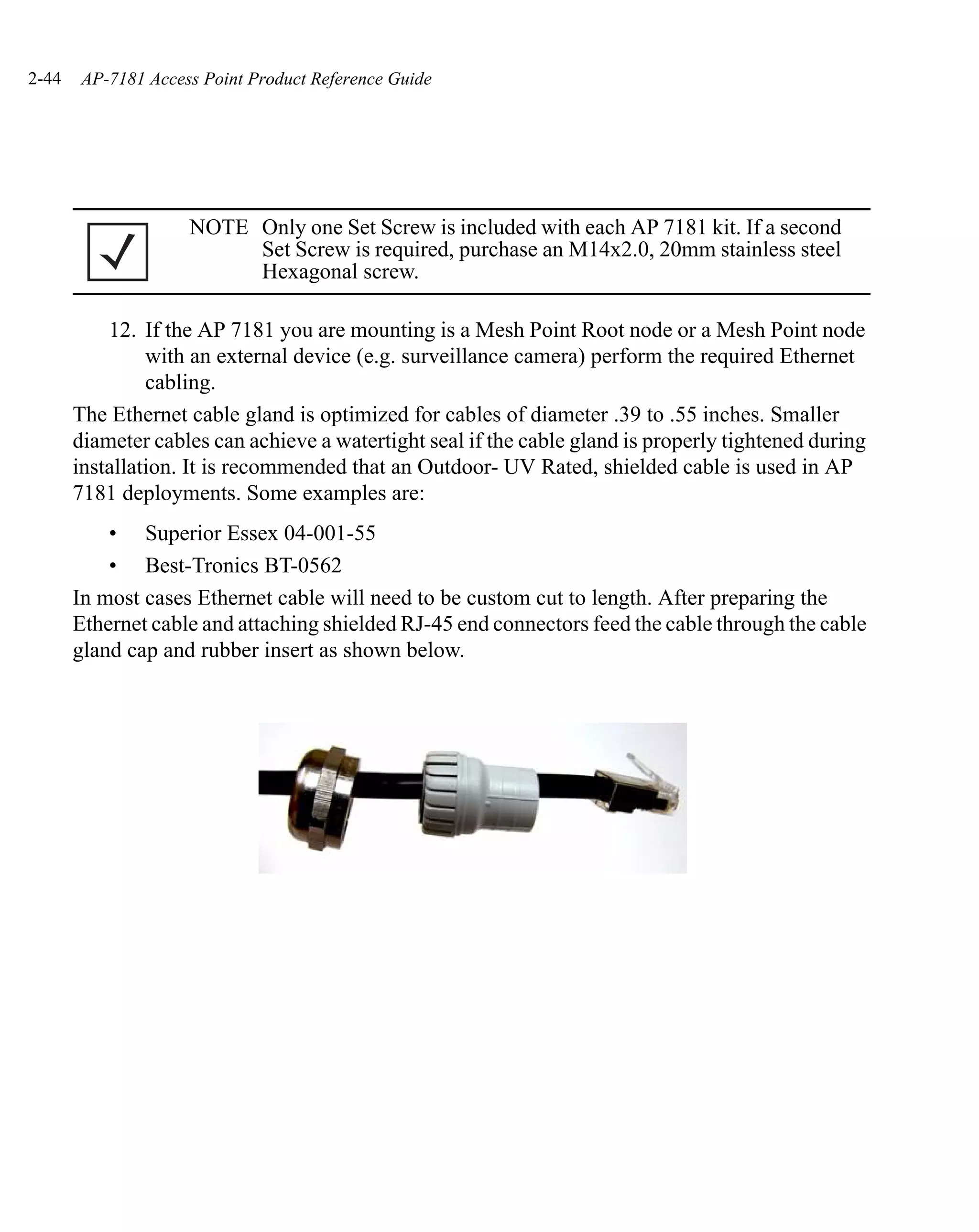
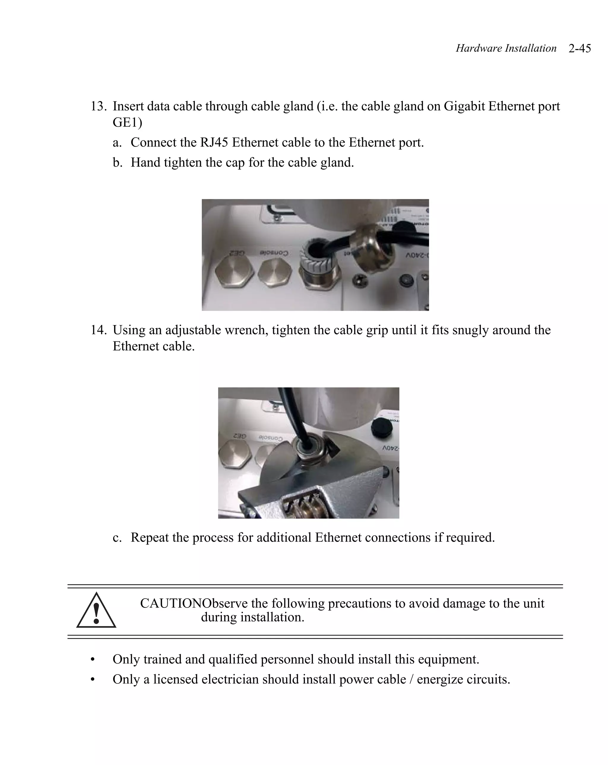
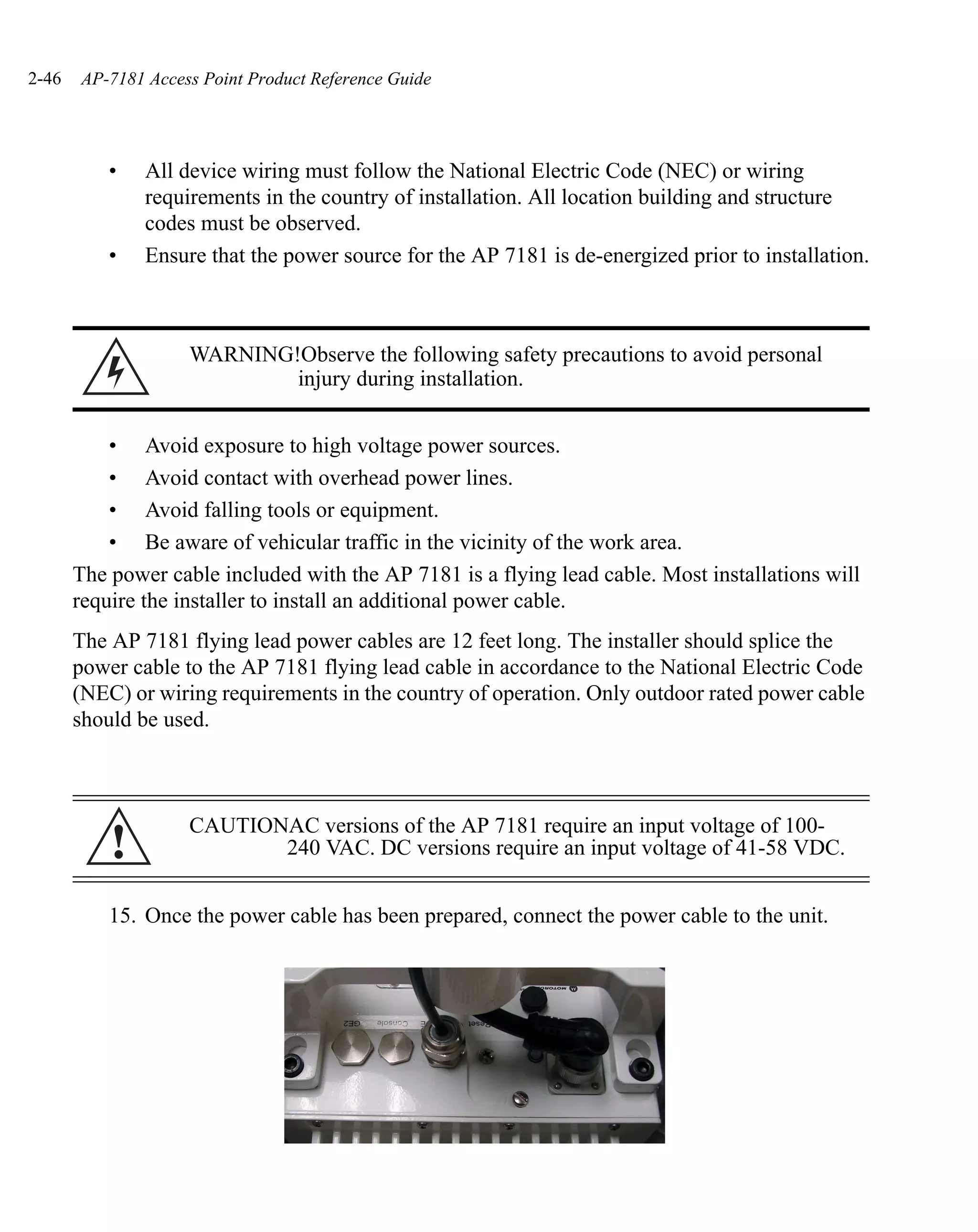
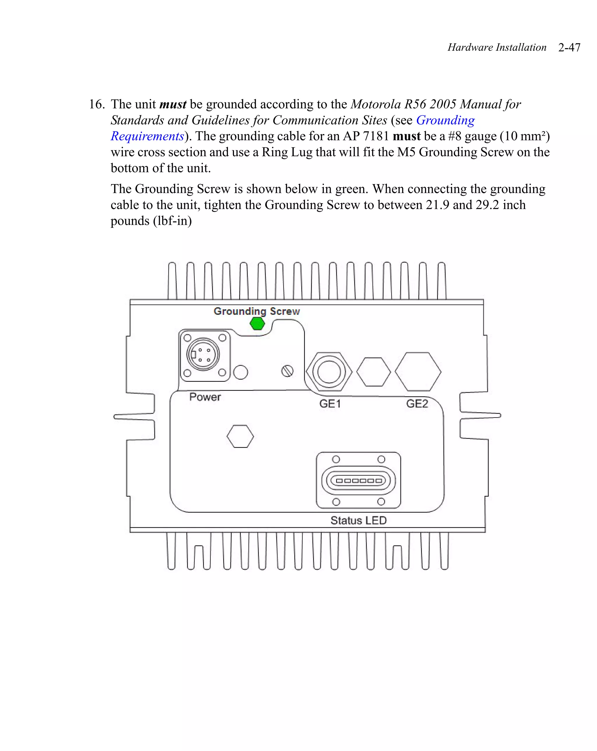
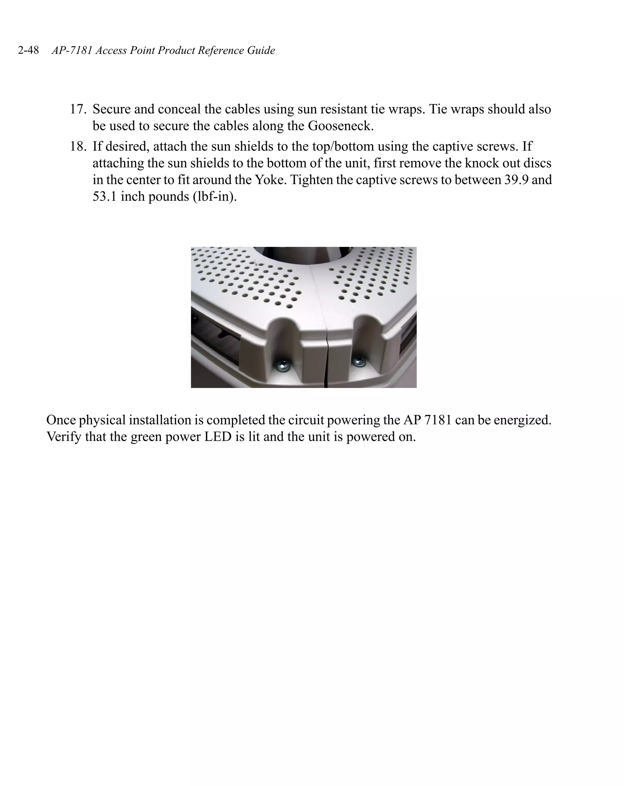
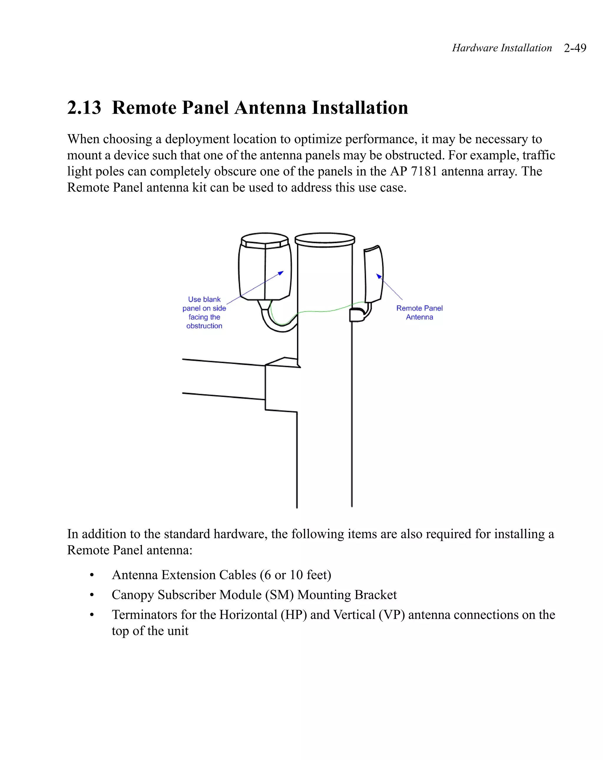
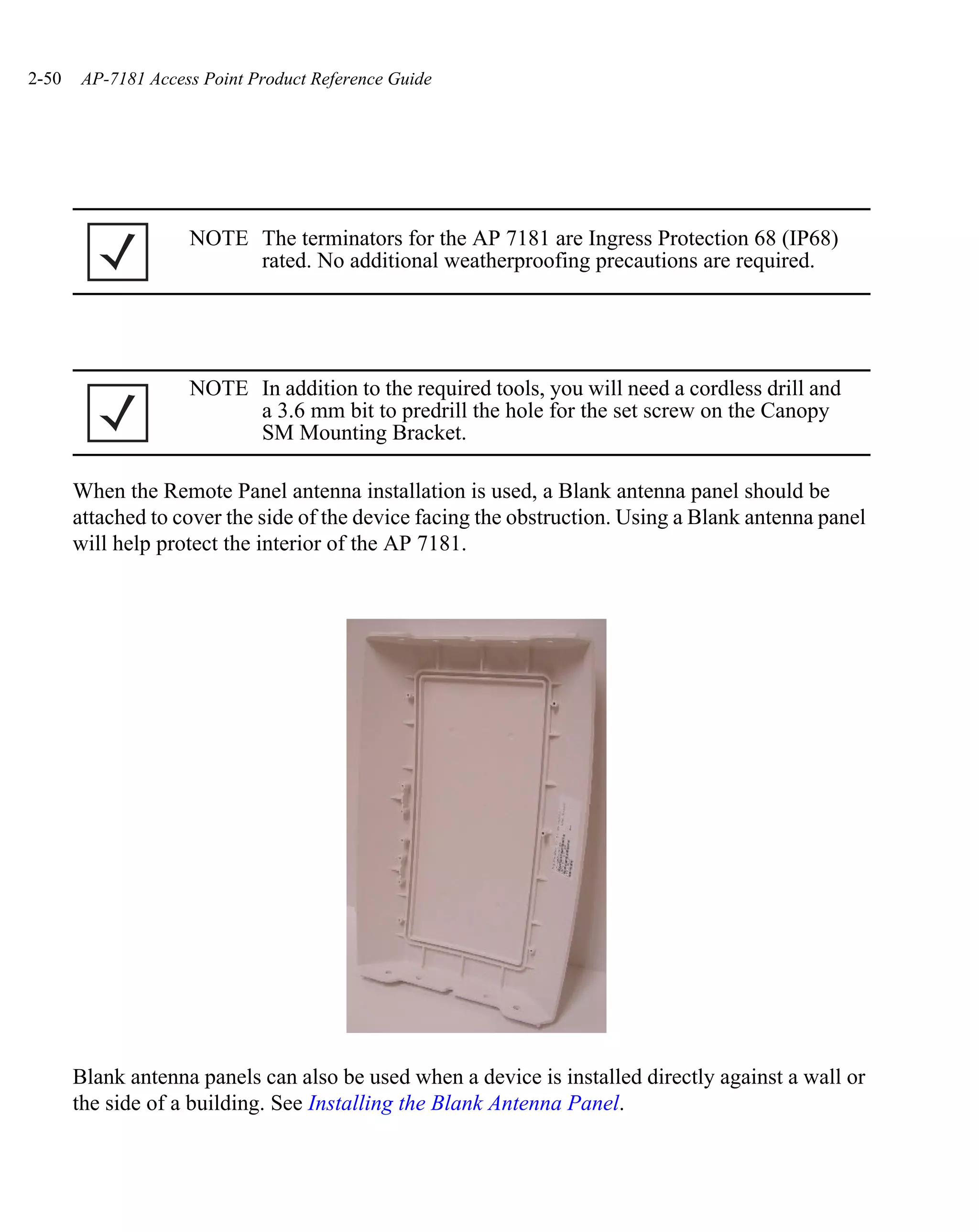
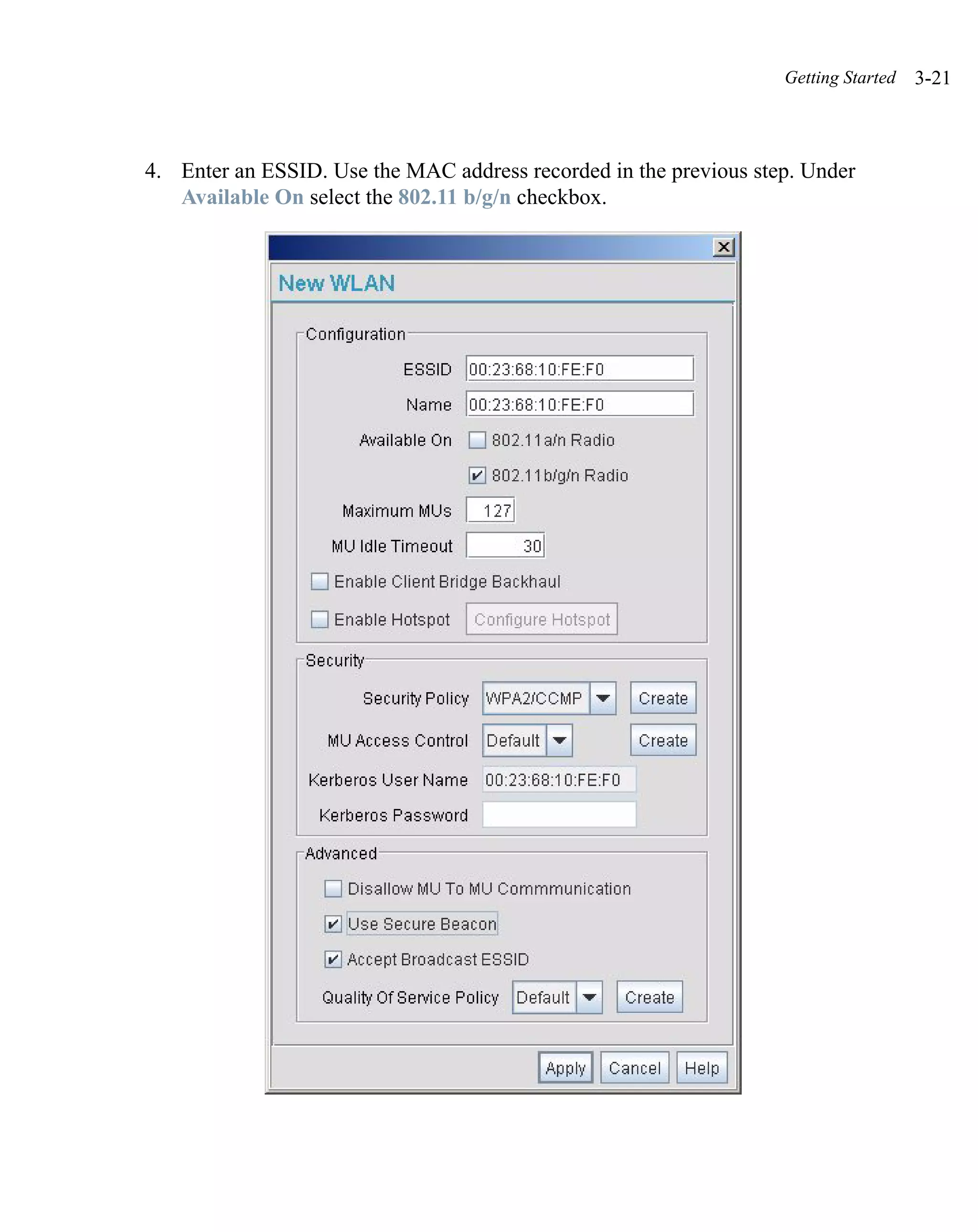
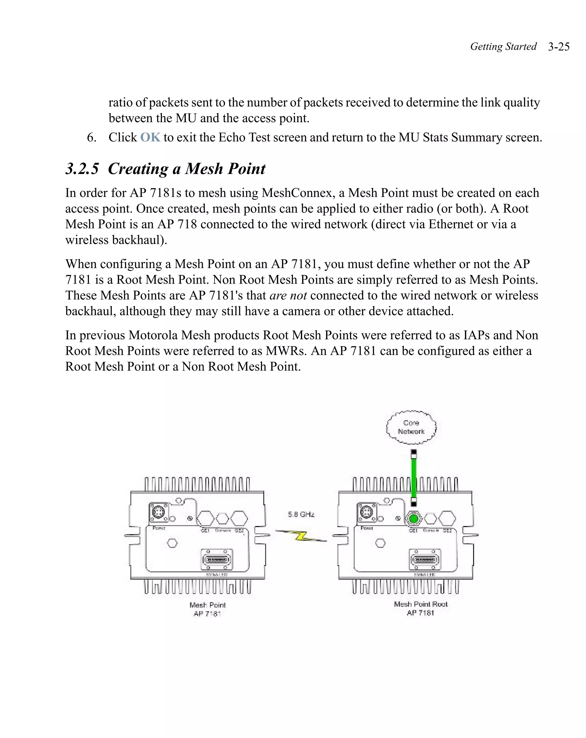
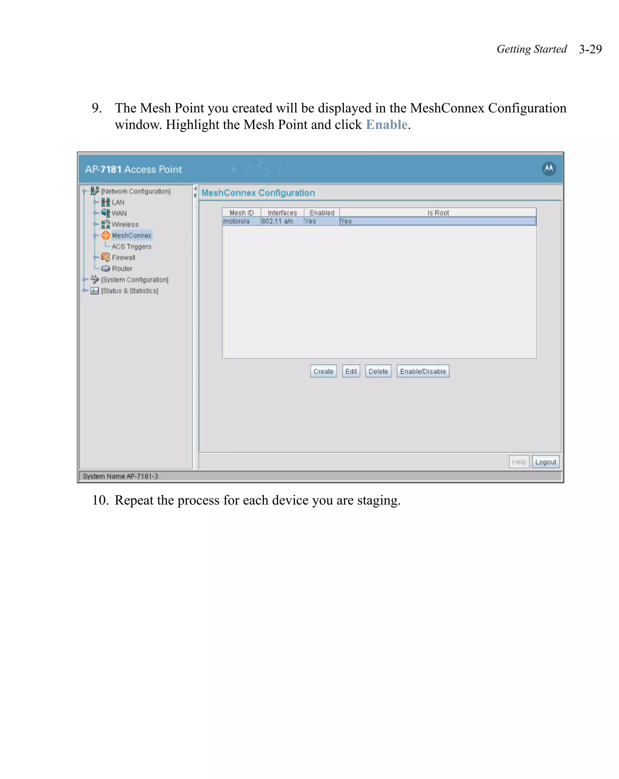
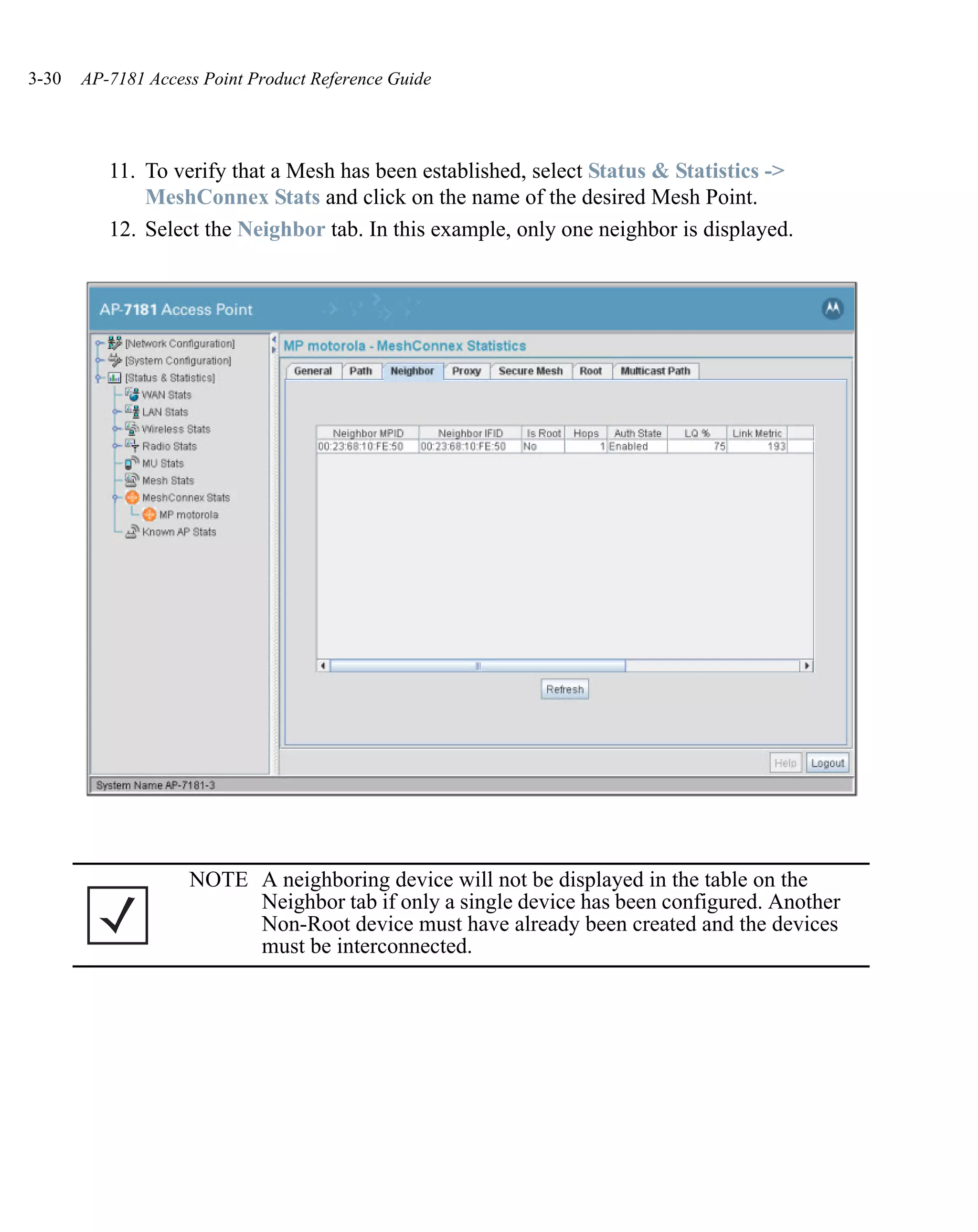
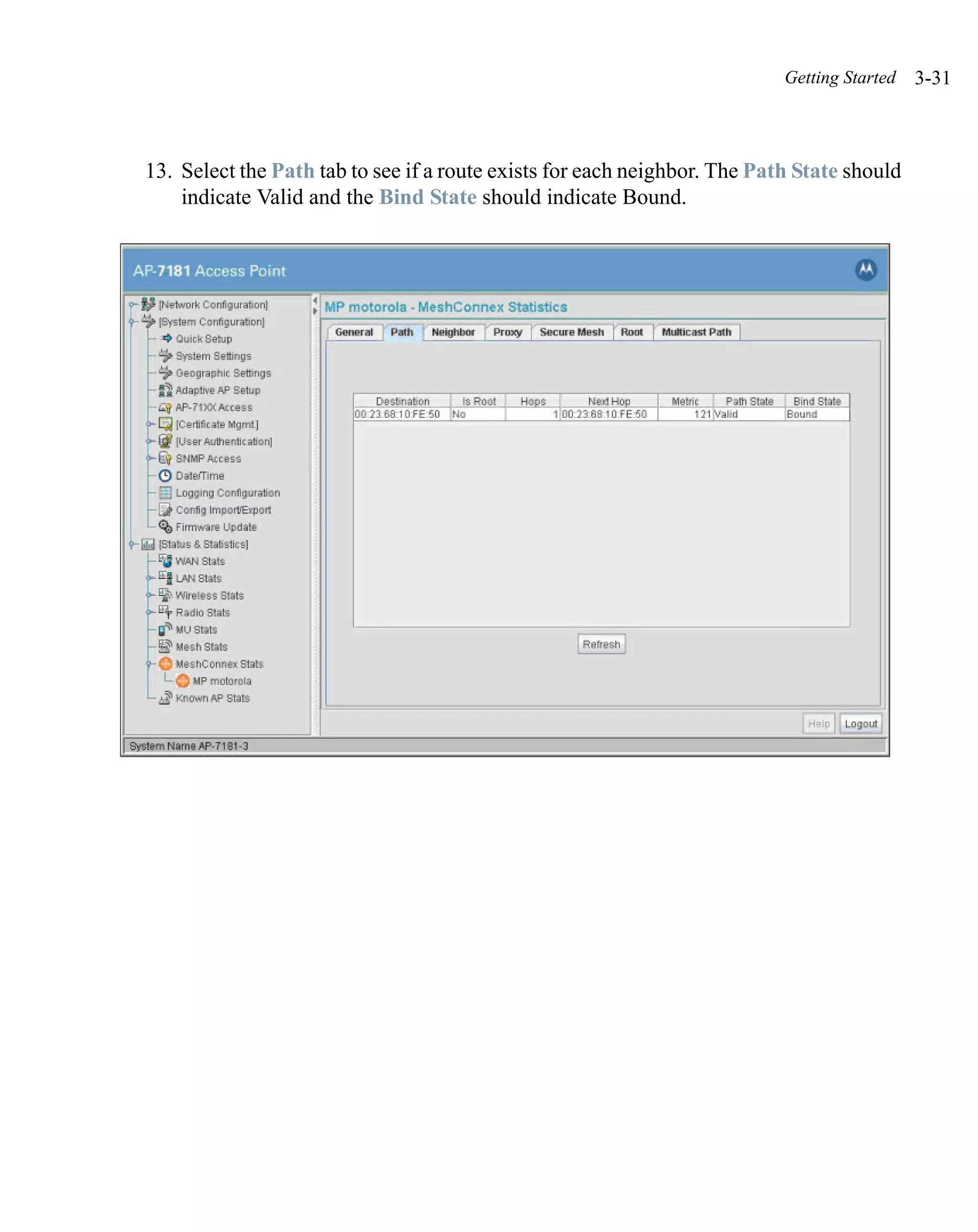
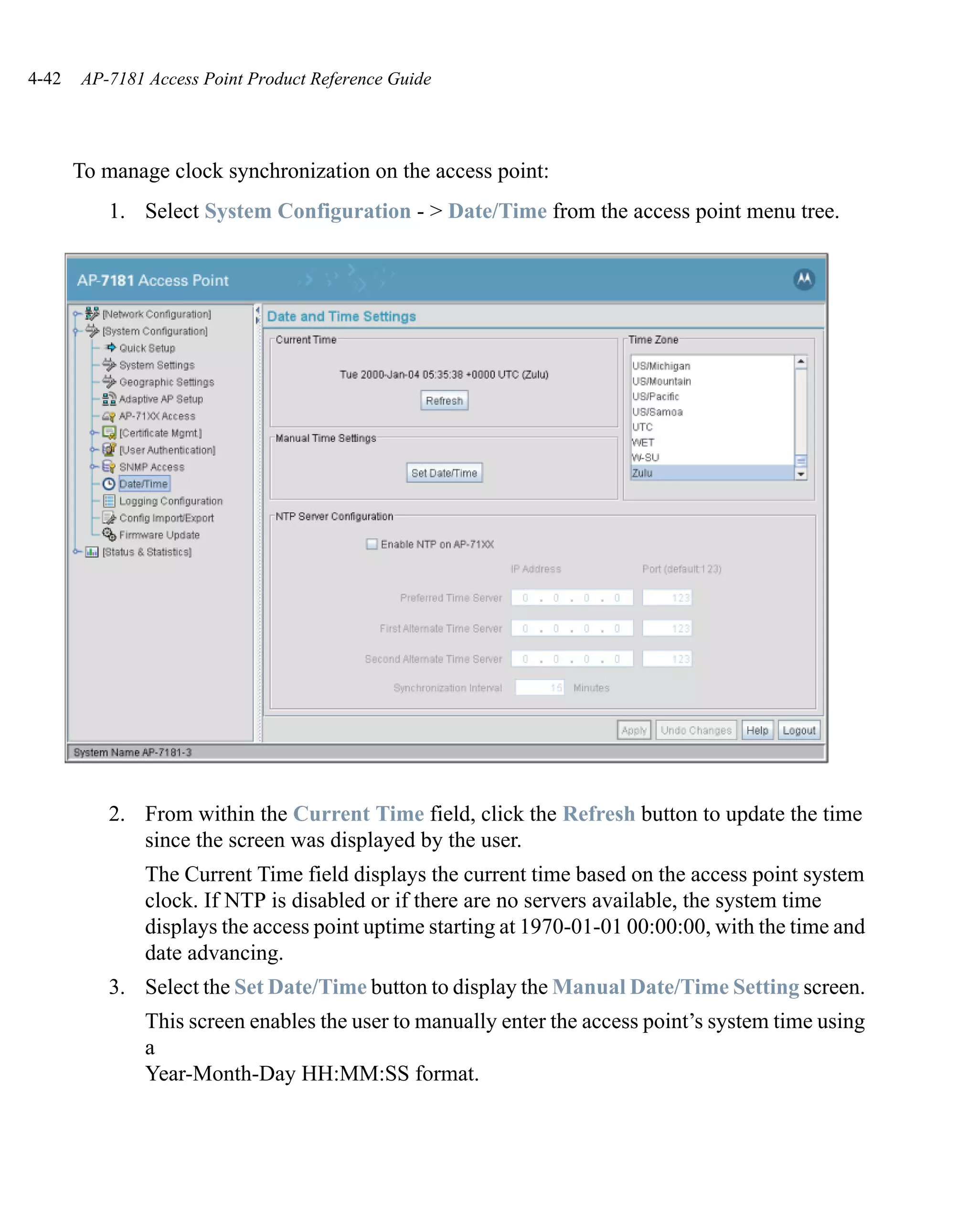
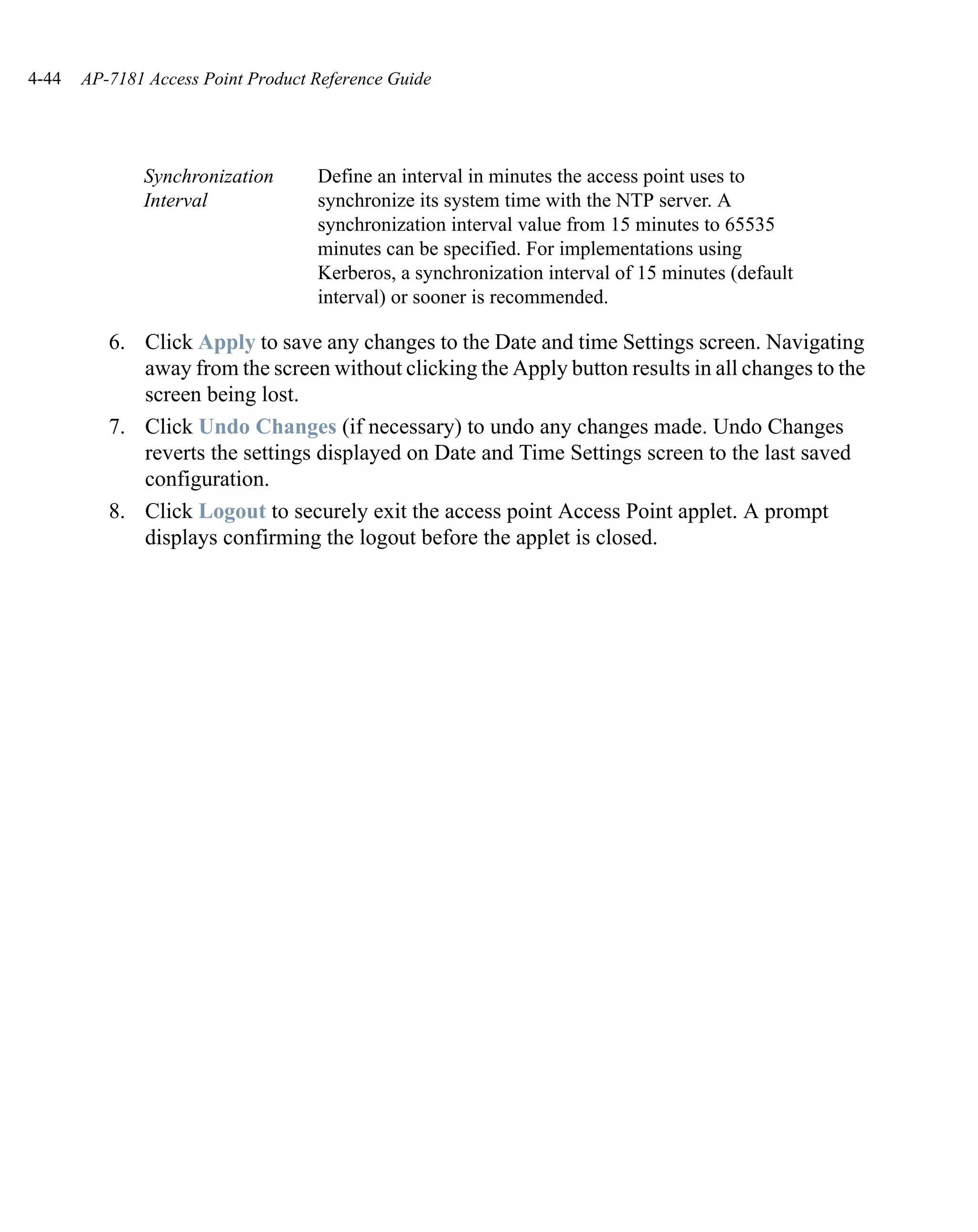
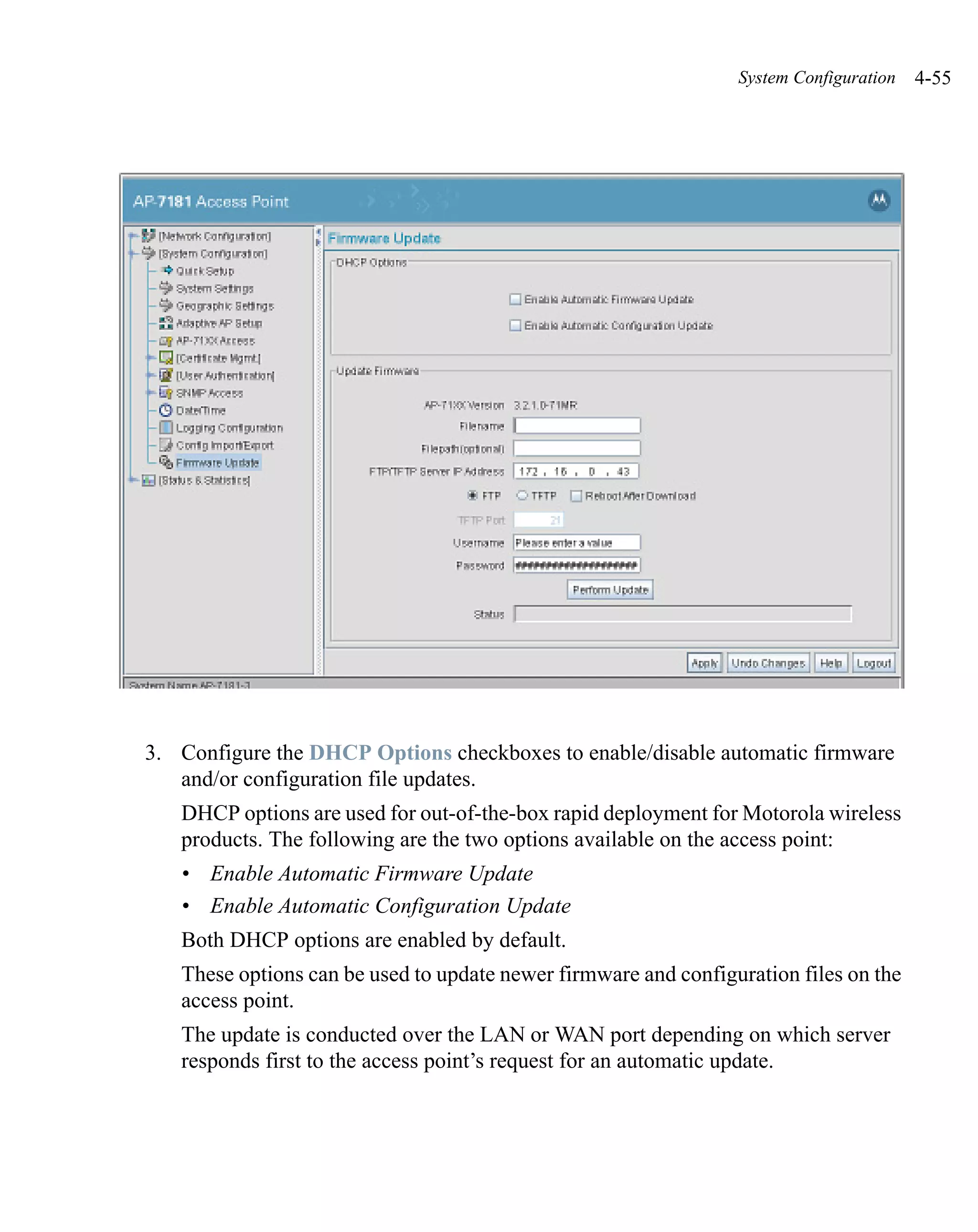
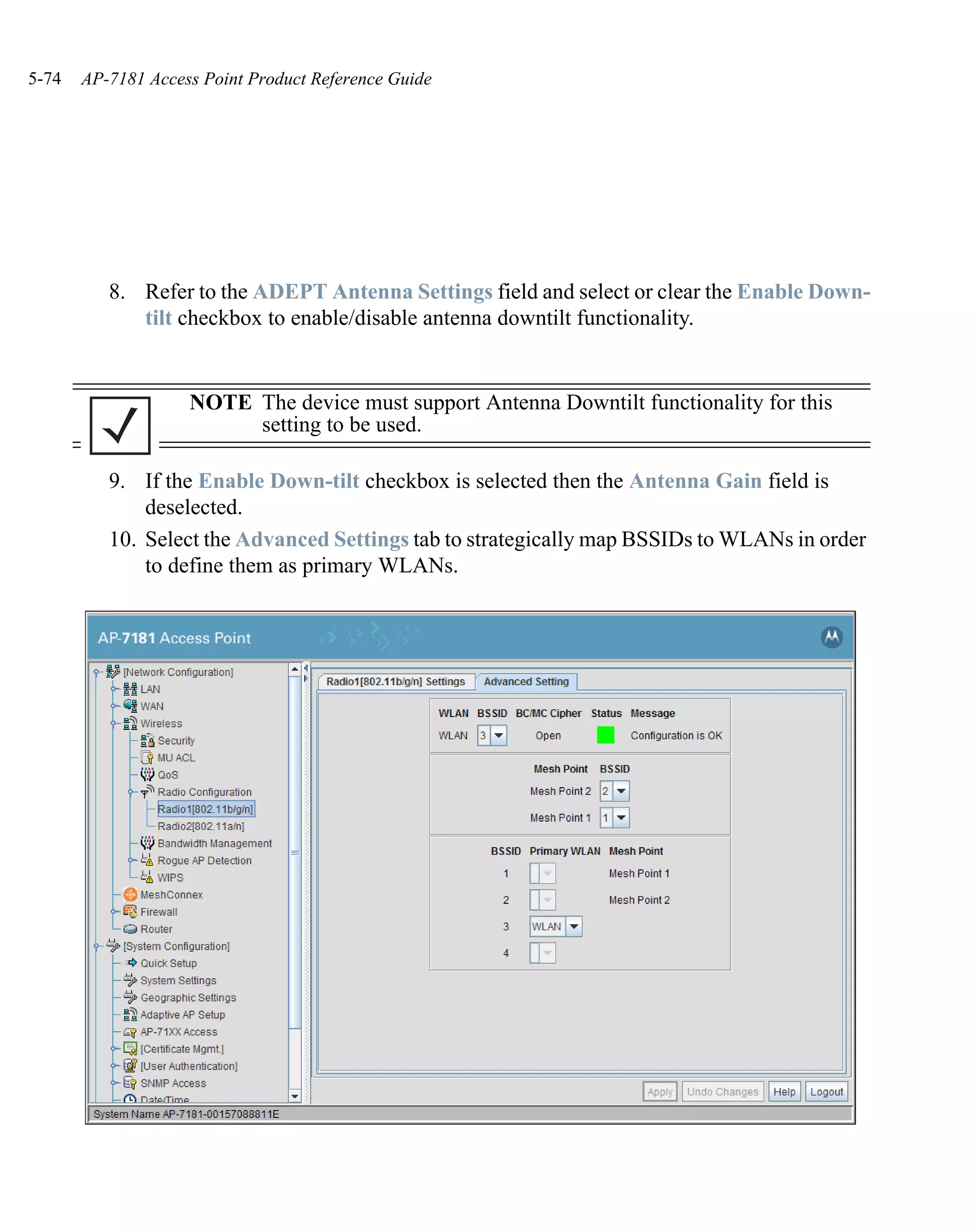
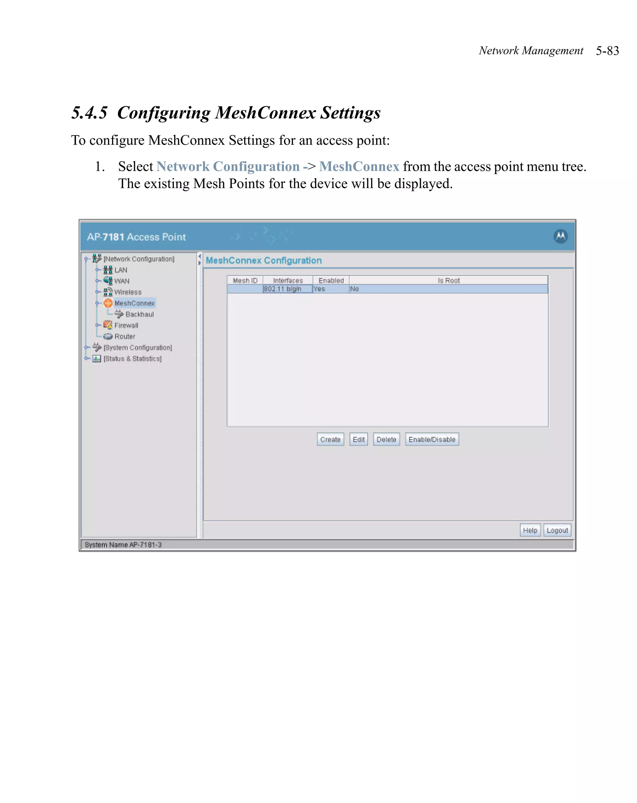
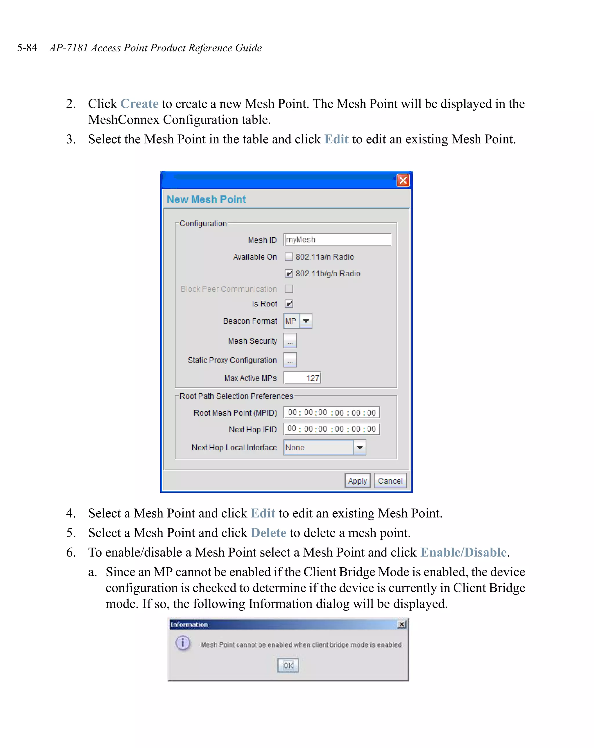
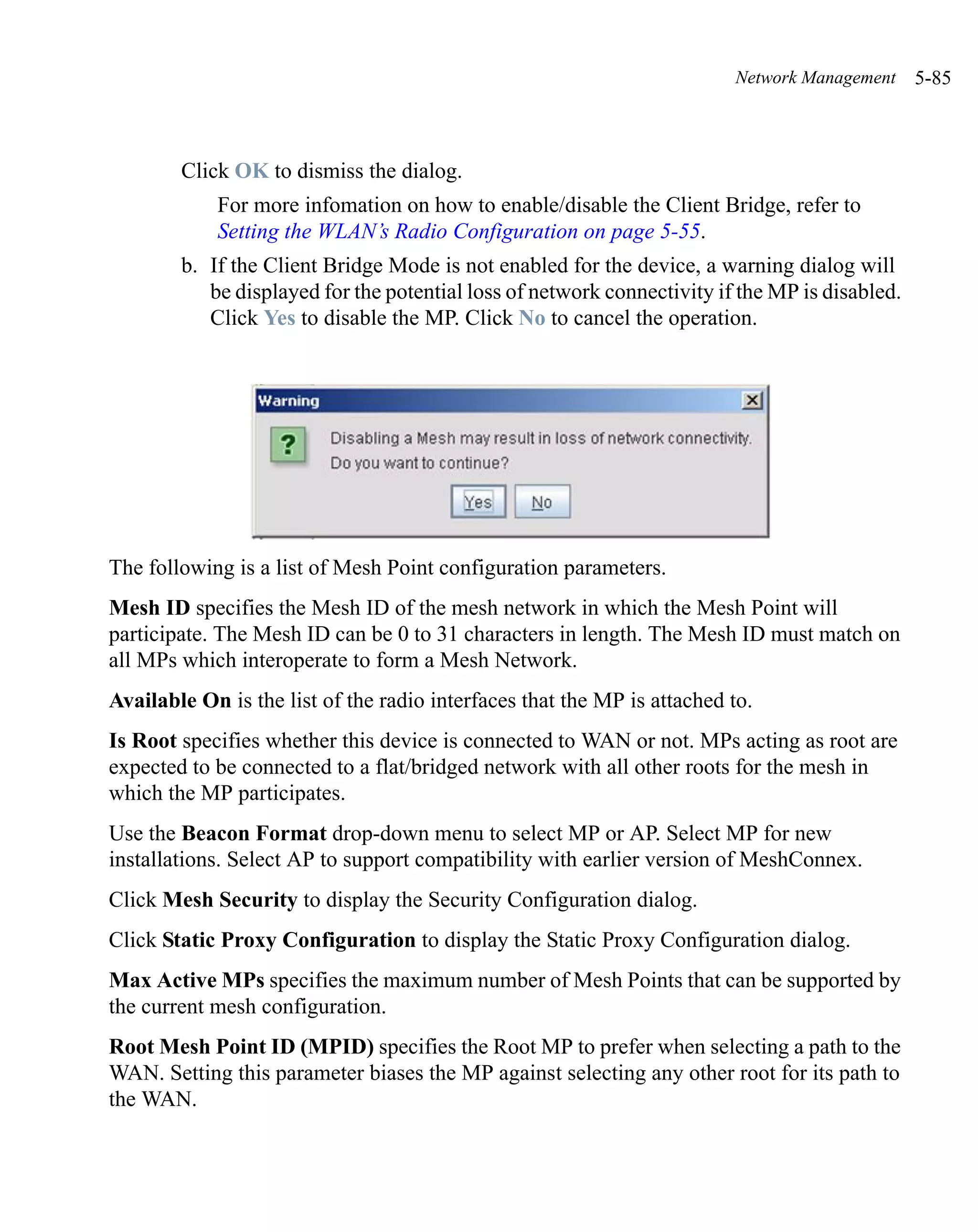
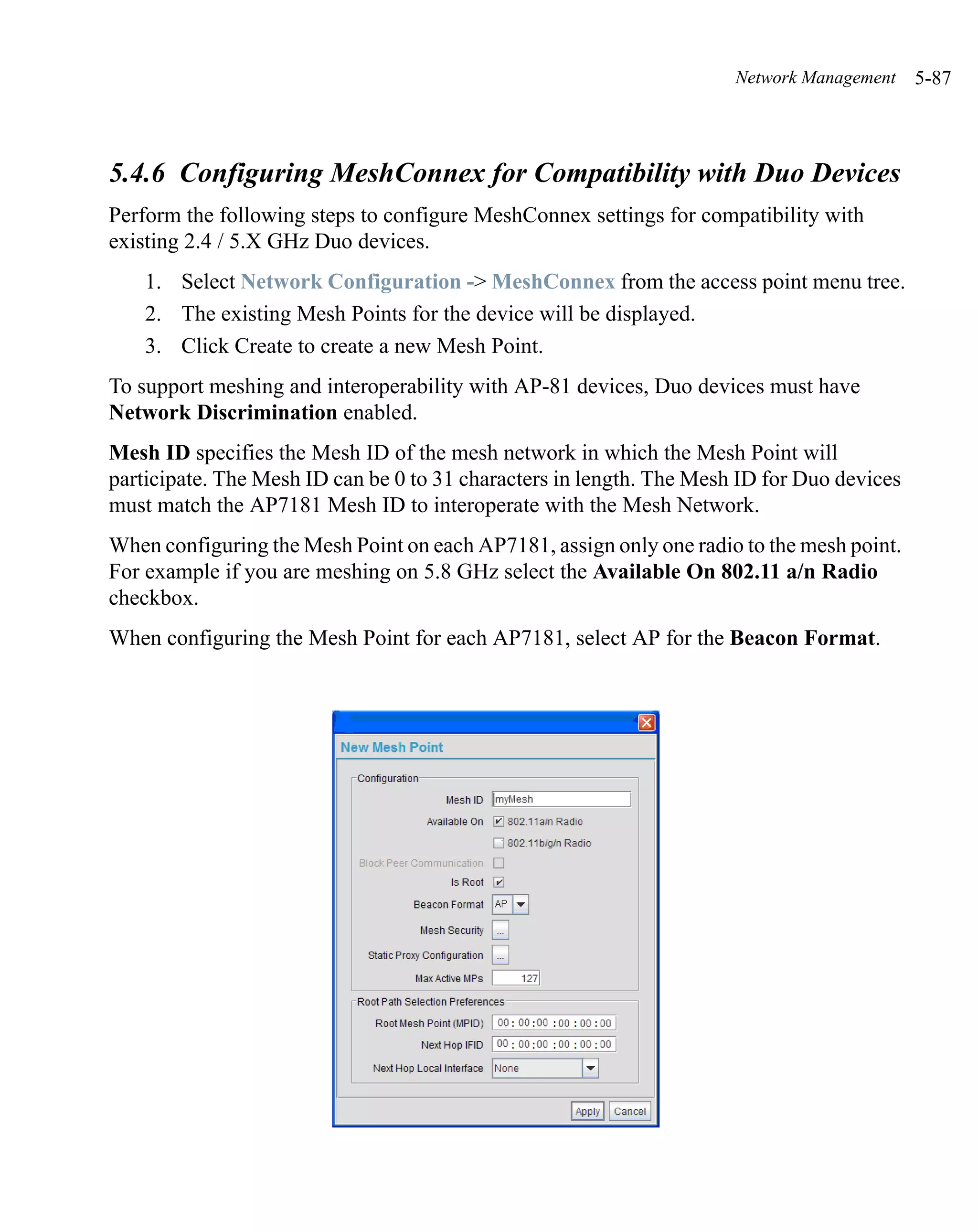
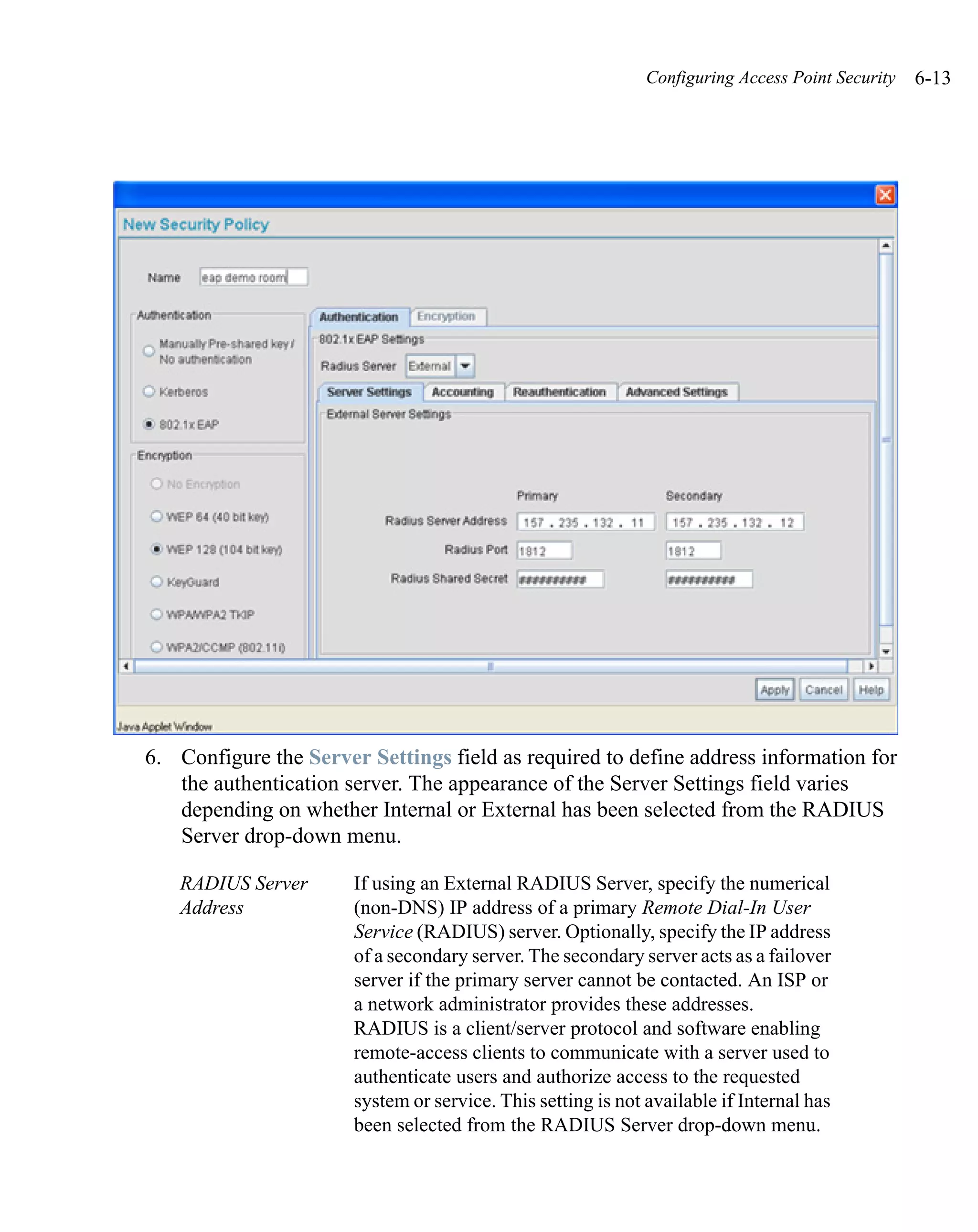
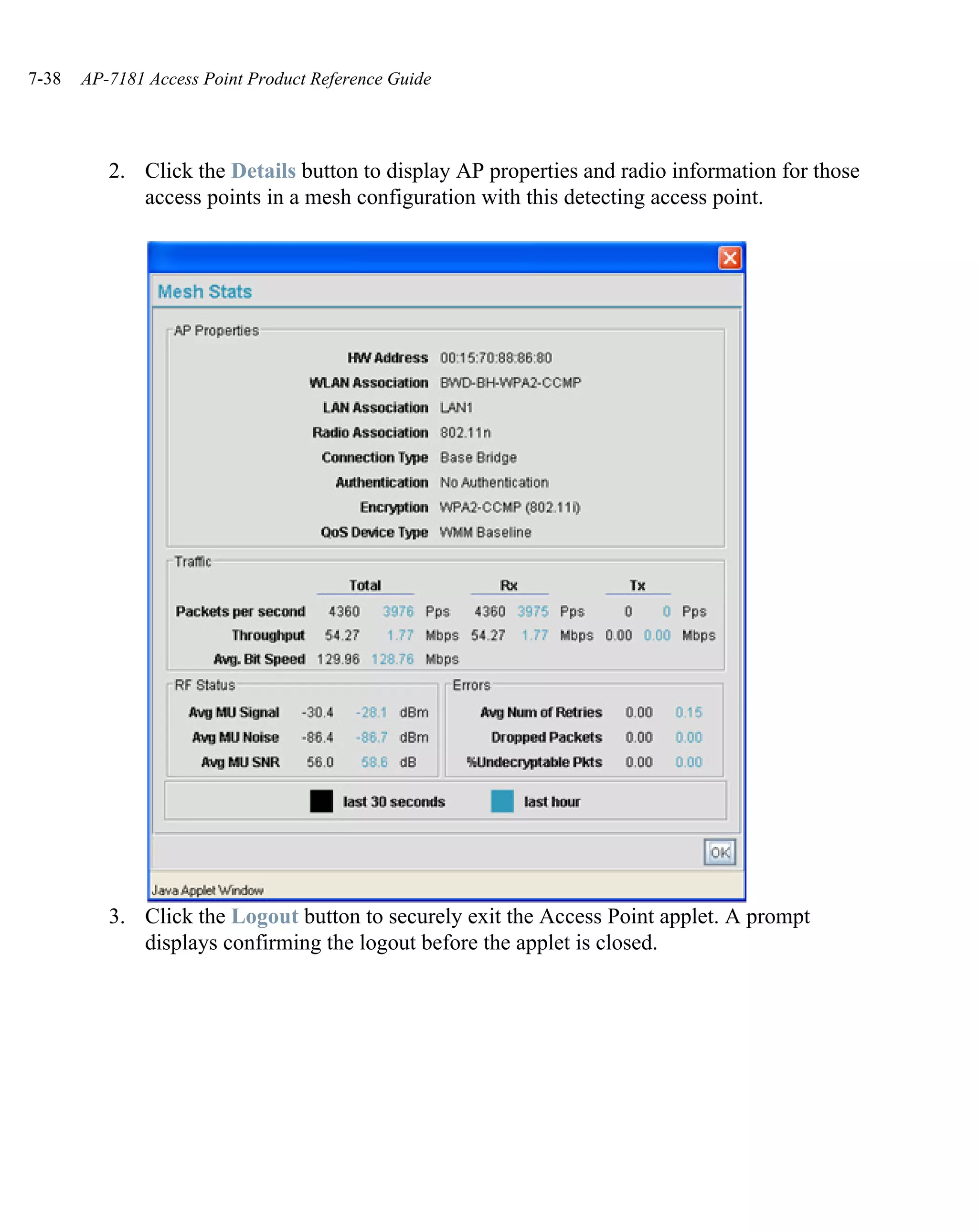
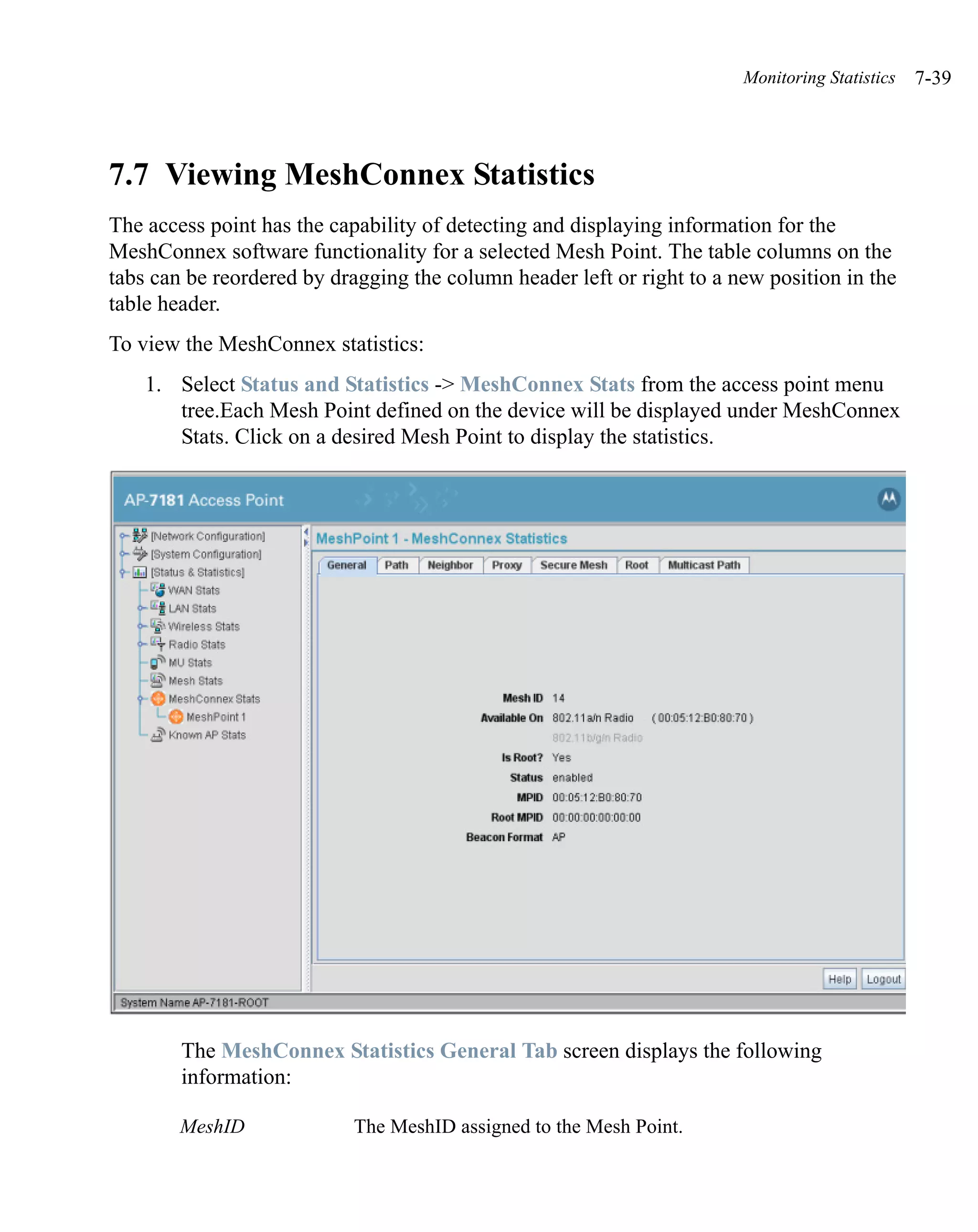
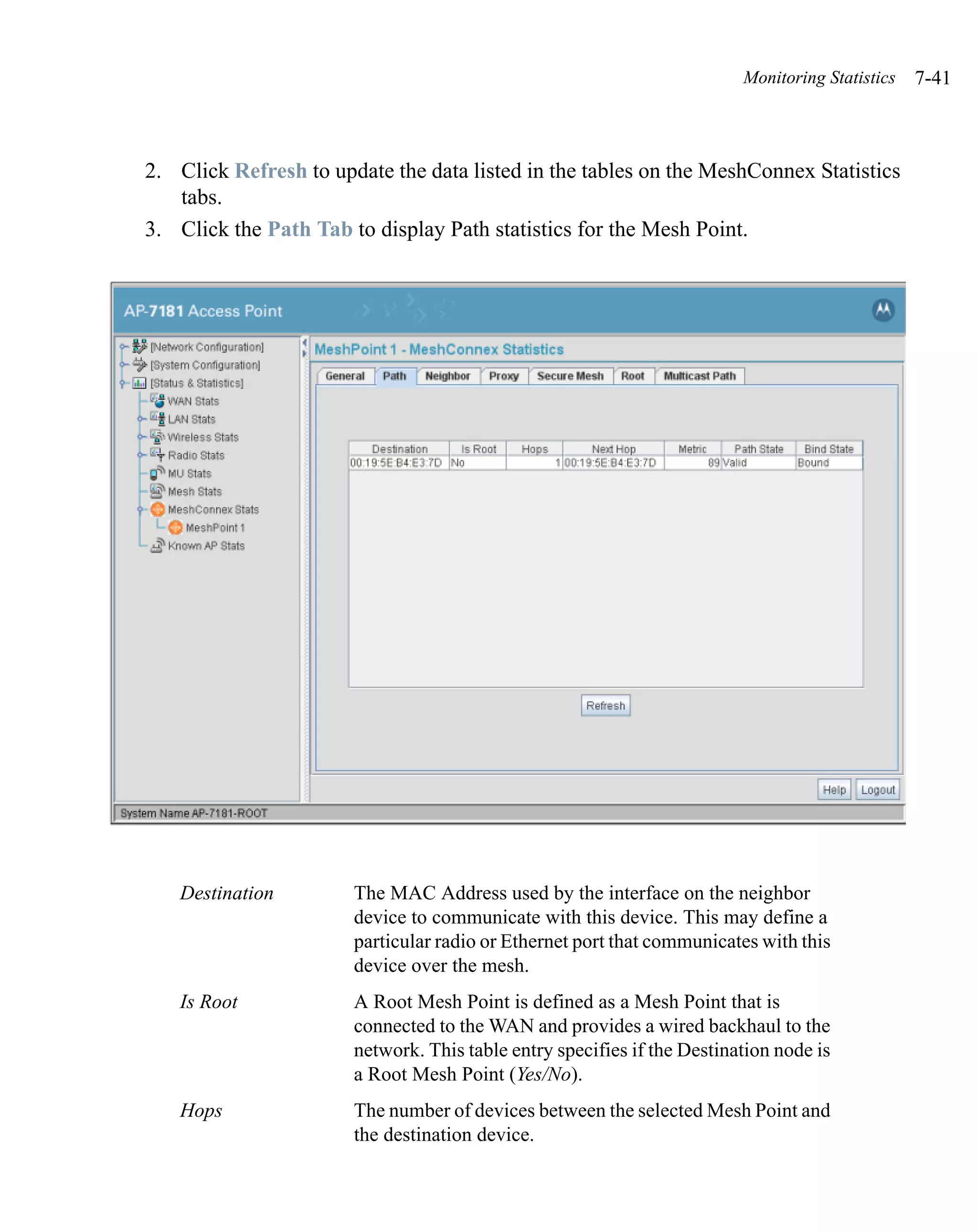
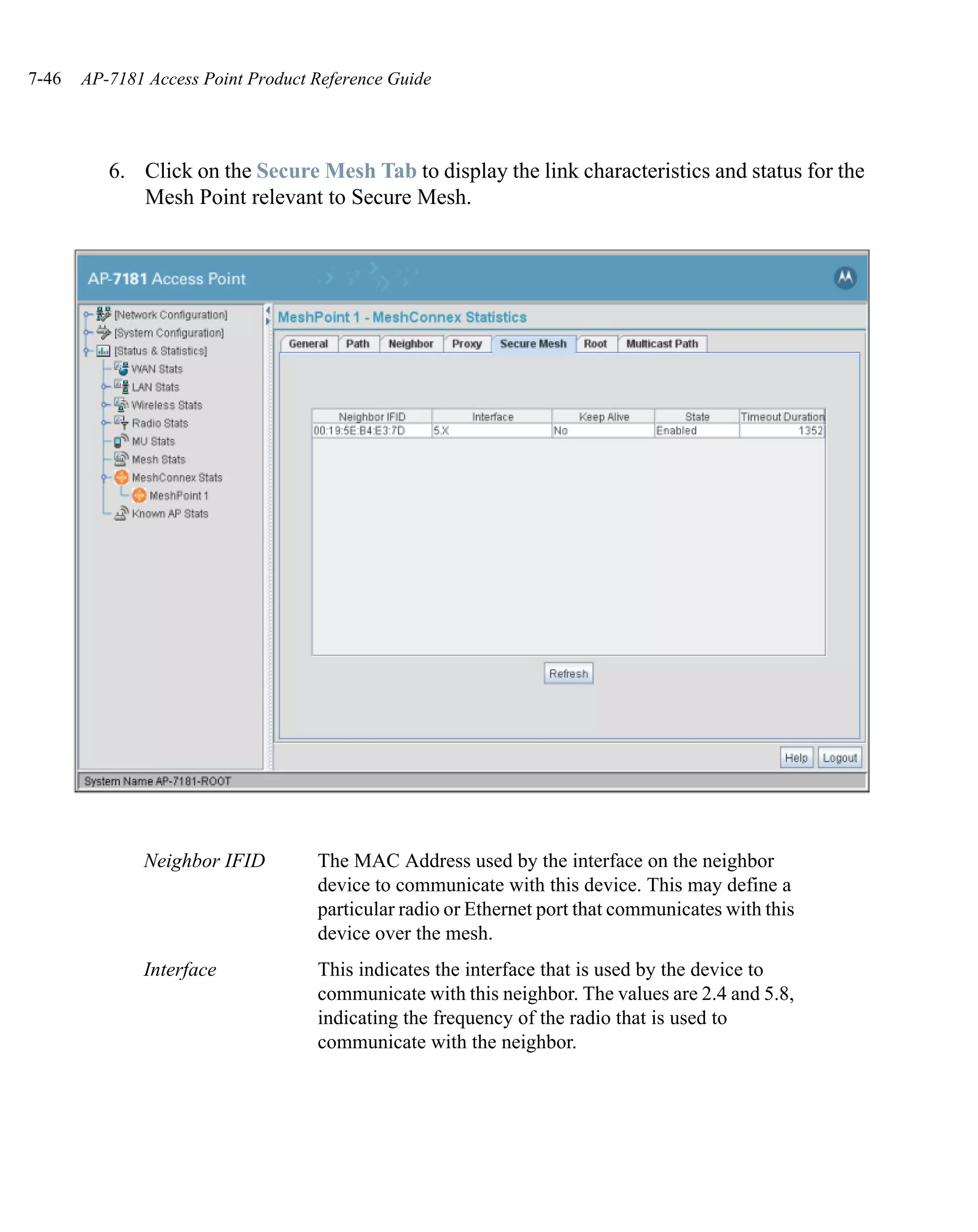
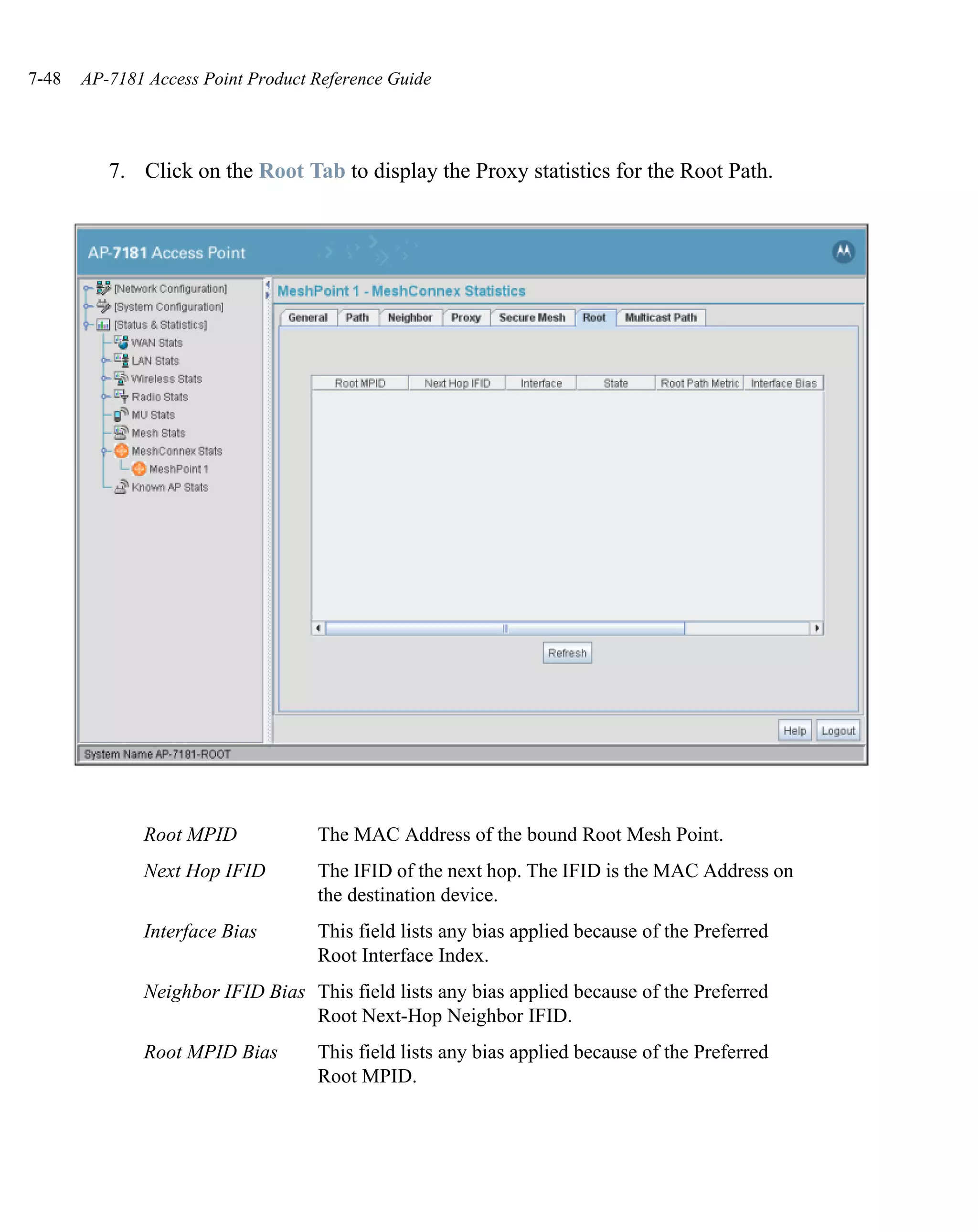
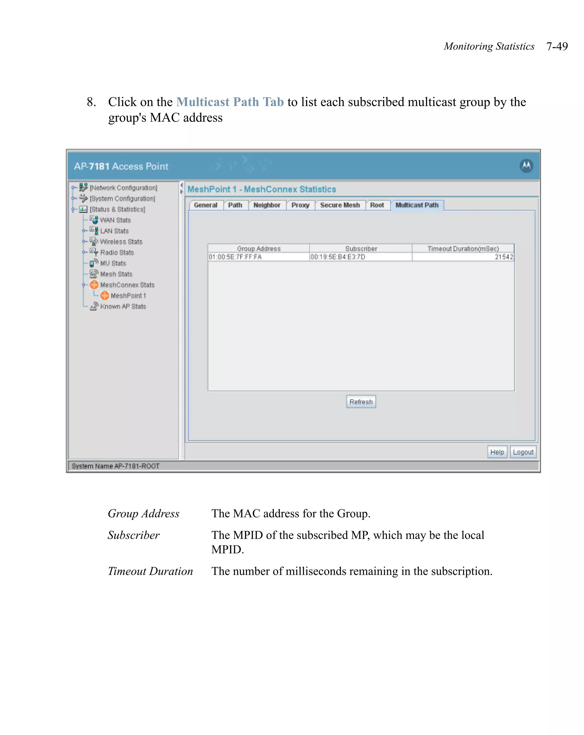
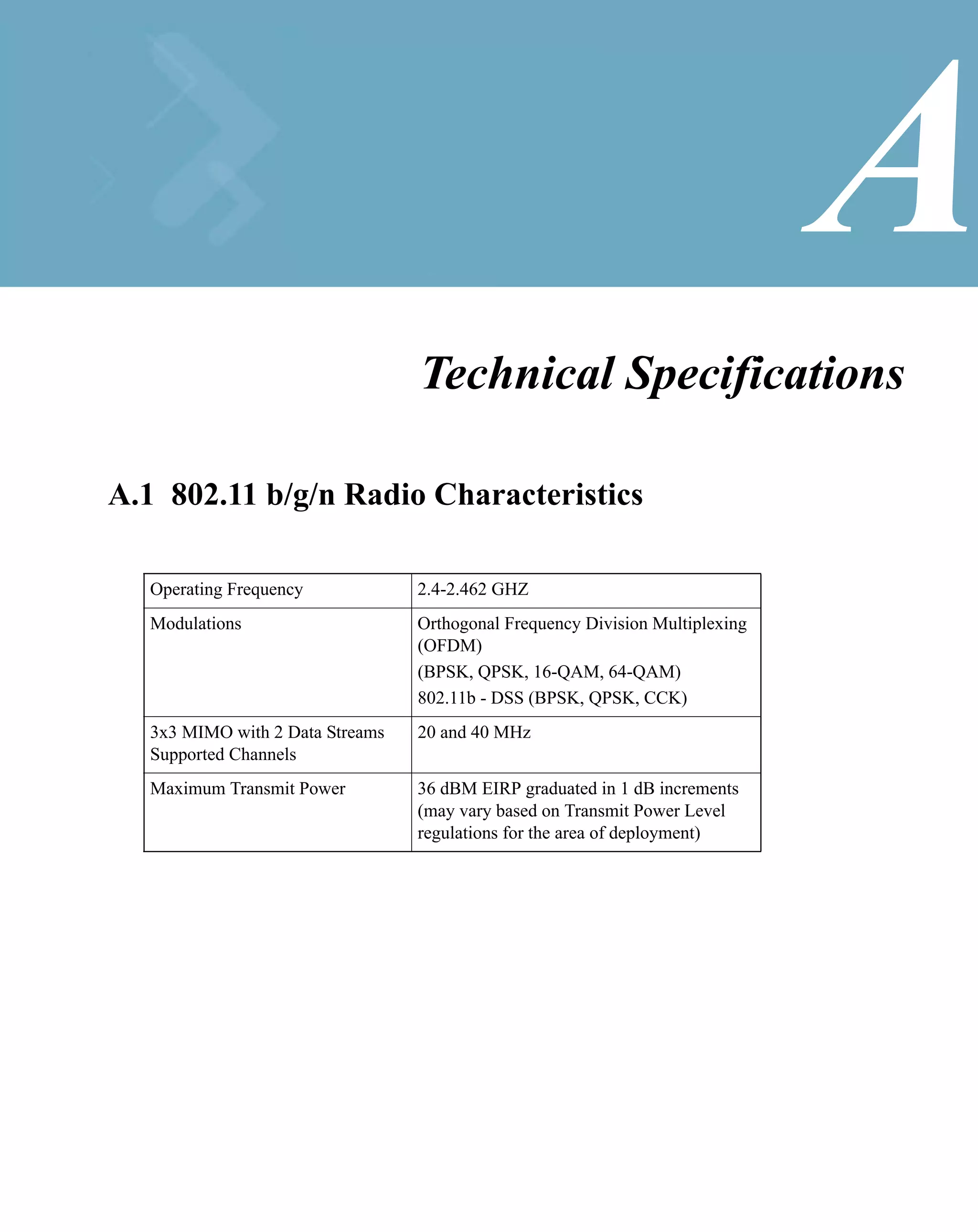
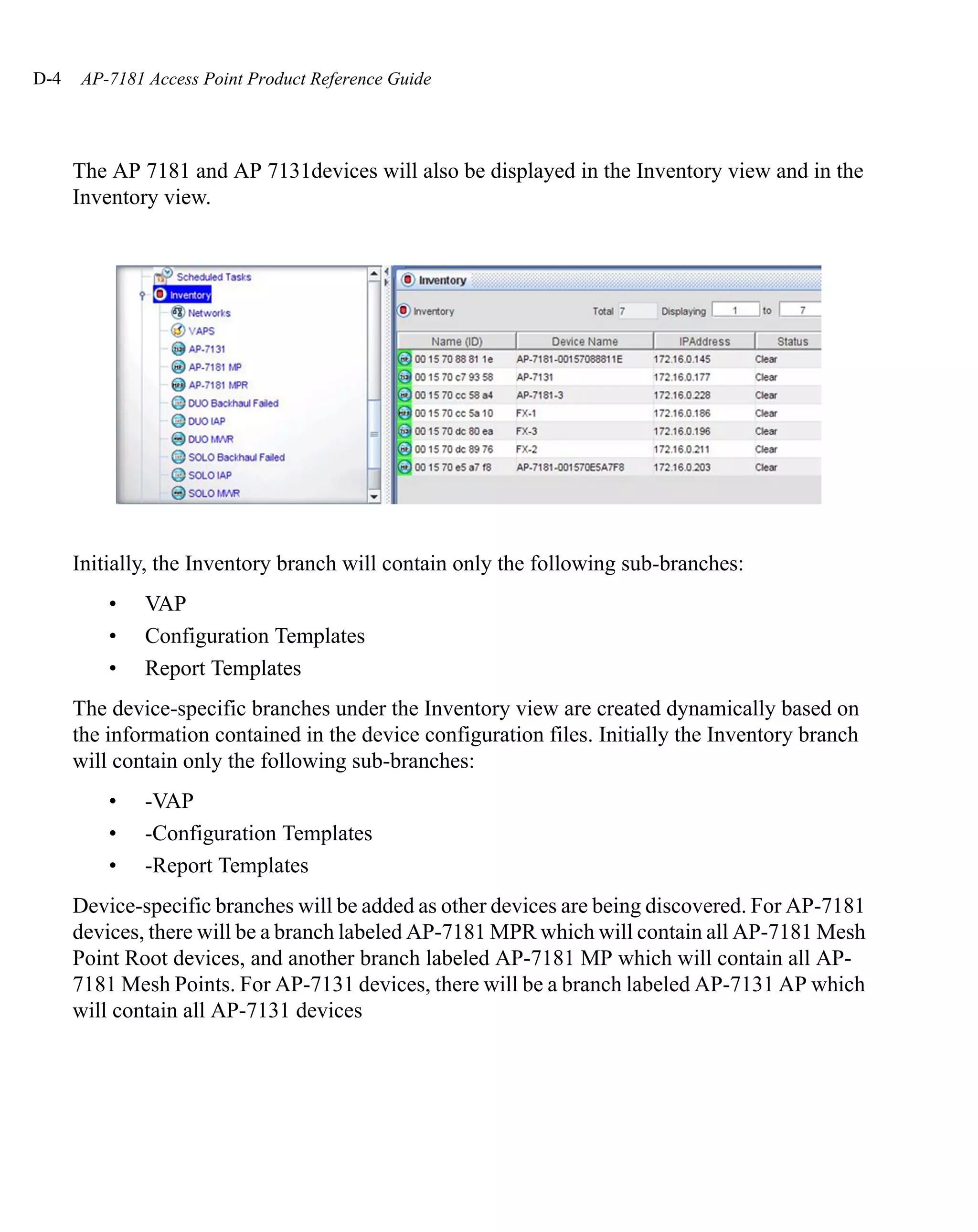
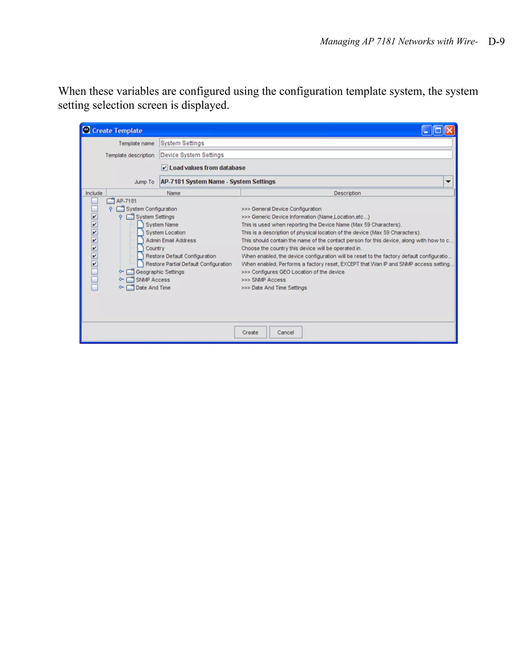
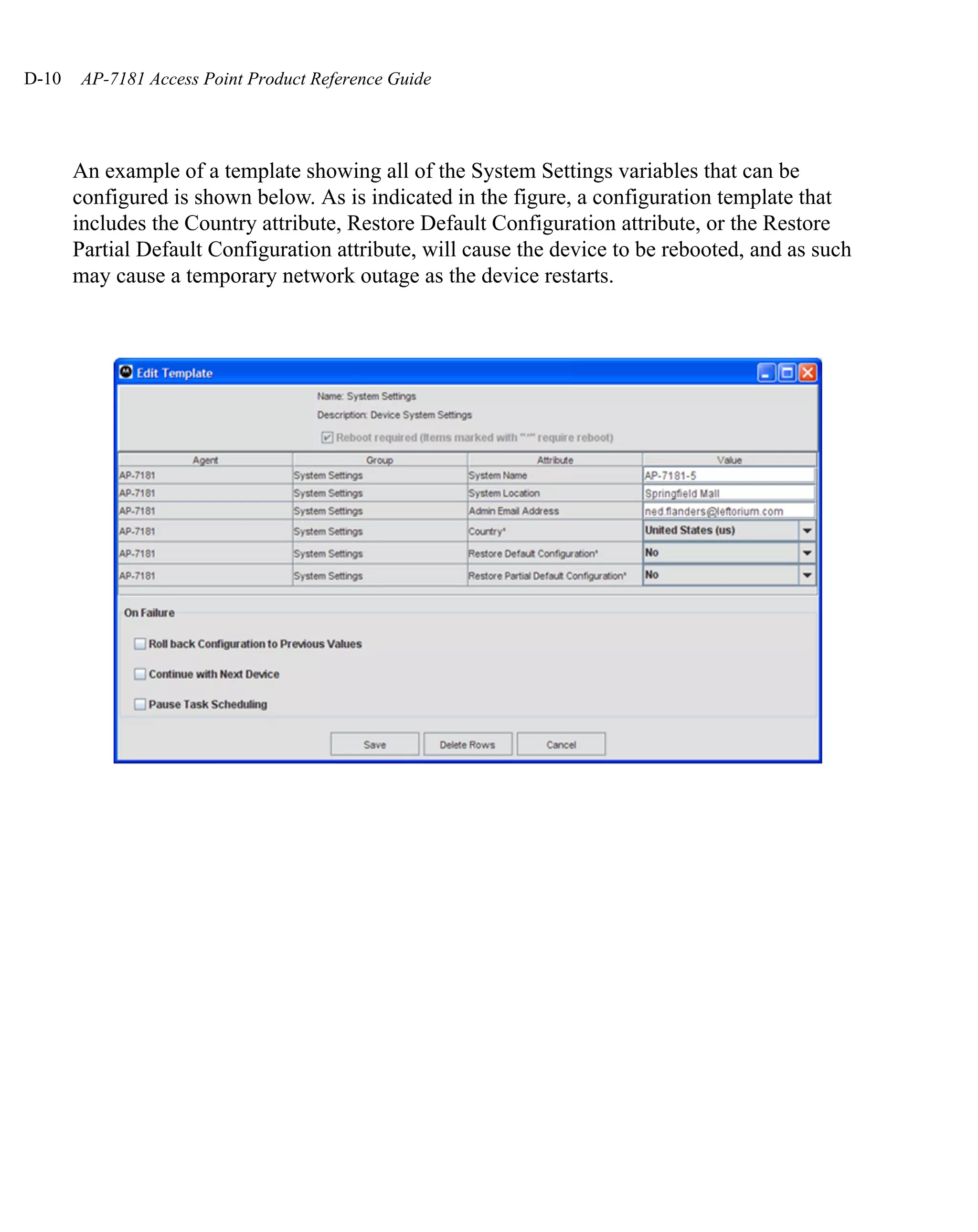
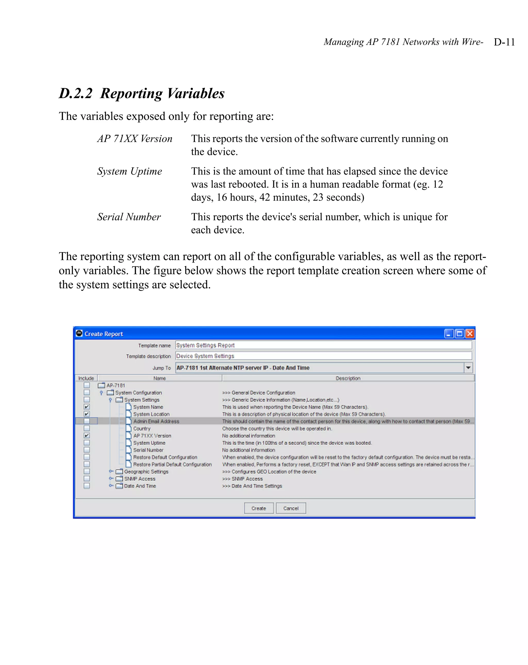
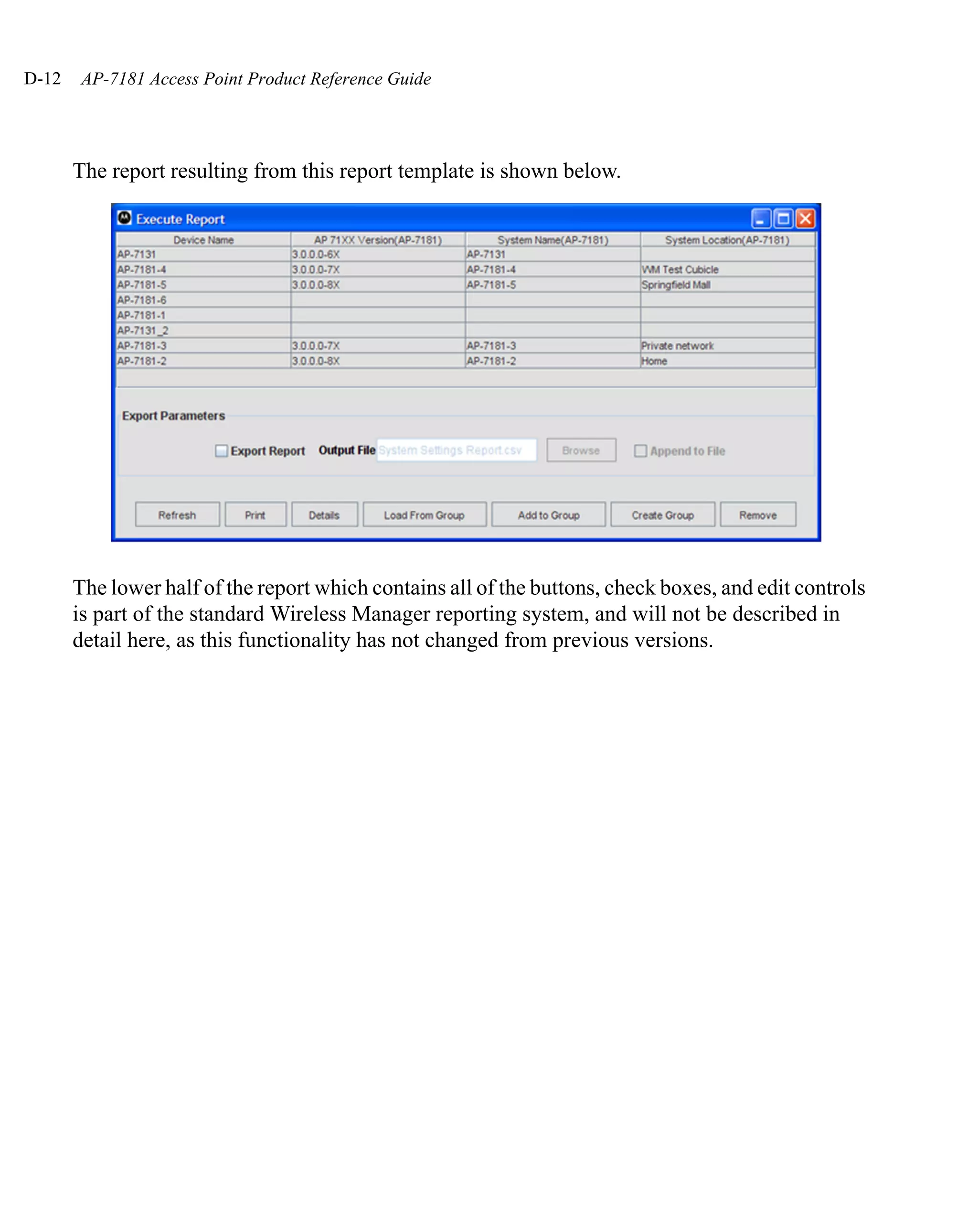
The document provides an overview and instructions for an AP 7181 Access Point, including: - Feature overview of the access point's mesh networking, 802.11n support, security, management, and other capabilities. - Instructions for hardware installation, including placement, mounting, power and antenna options, and physical connections. - Details on initial setup and staging of the access point prior to field installation.


![Vibe Coding vs. Spec-Driven Development [Free Meetup]](https://cdn.slidesharecdn.com/ss_thumbnails/vibecodingvsspecdrivendevelopment-251209105622-43f455e7-thumbnail.jpg?width=640&height=640&fit=bounds)


