Downloaded 15 times


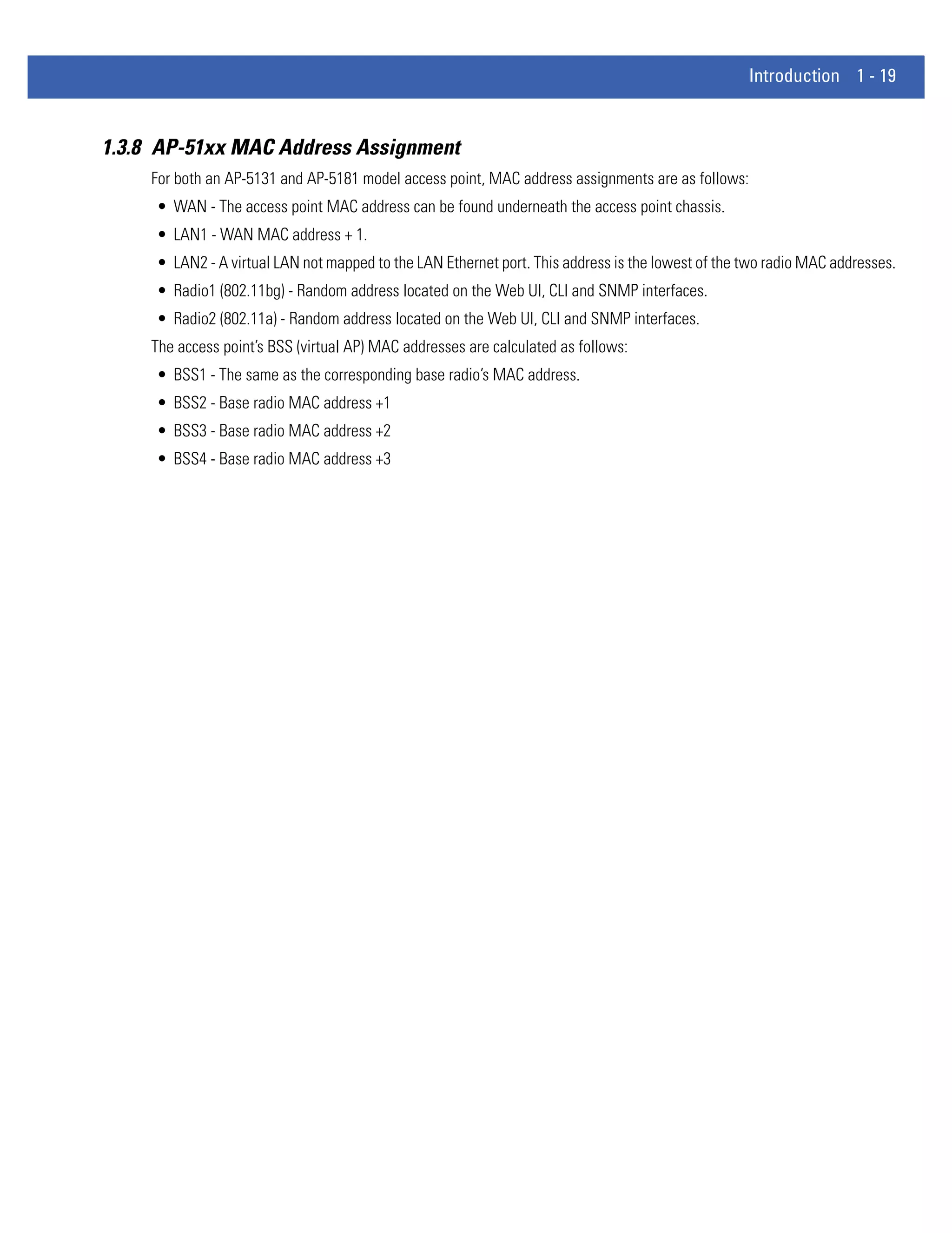


![4 - 42 WiNG 4.4 AP-5131 Product Reference Guide
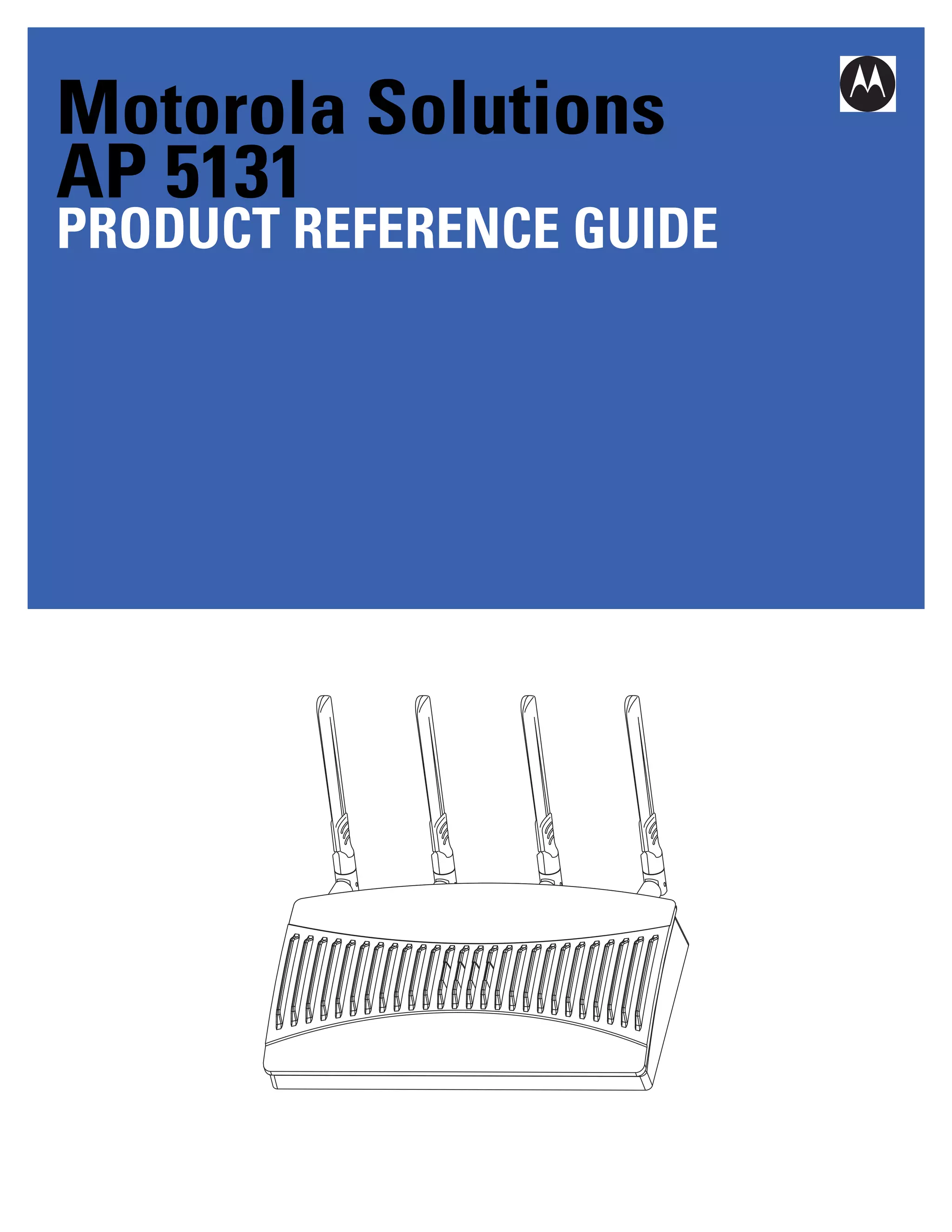
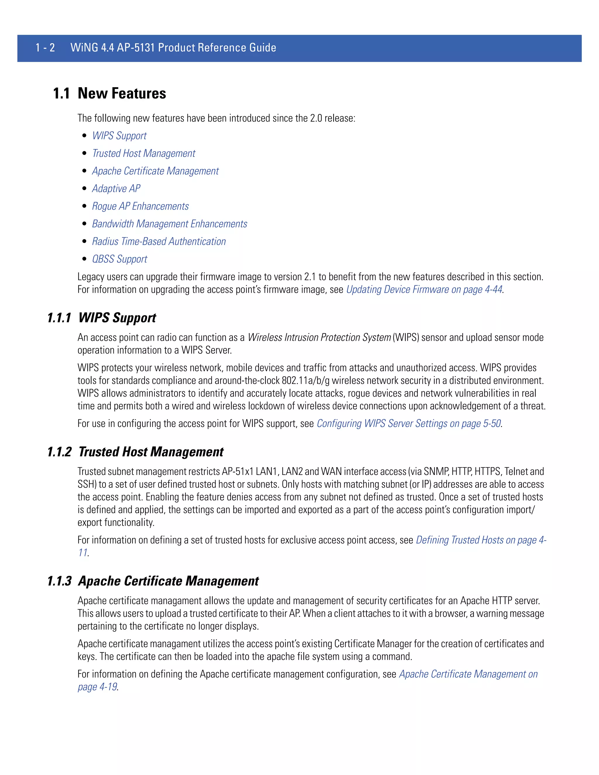
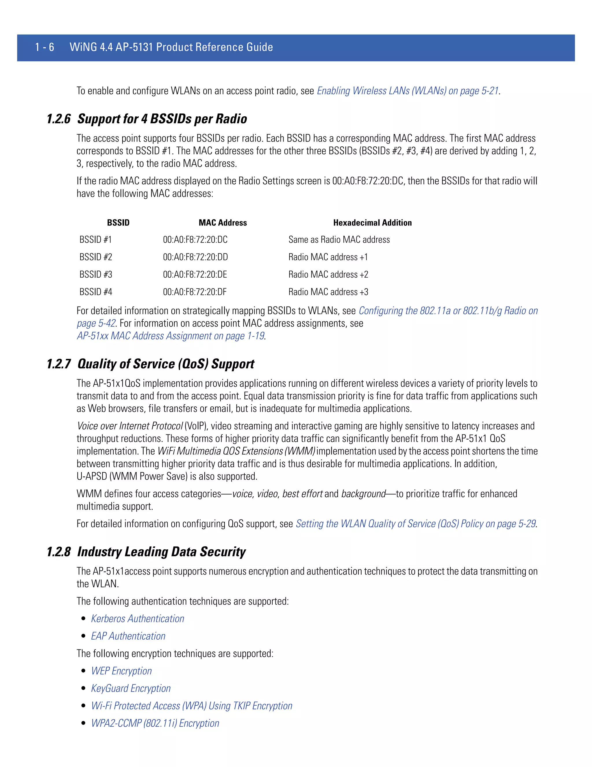
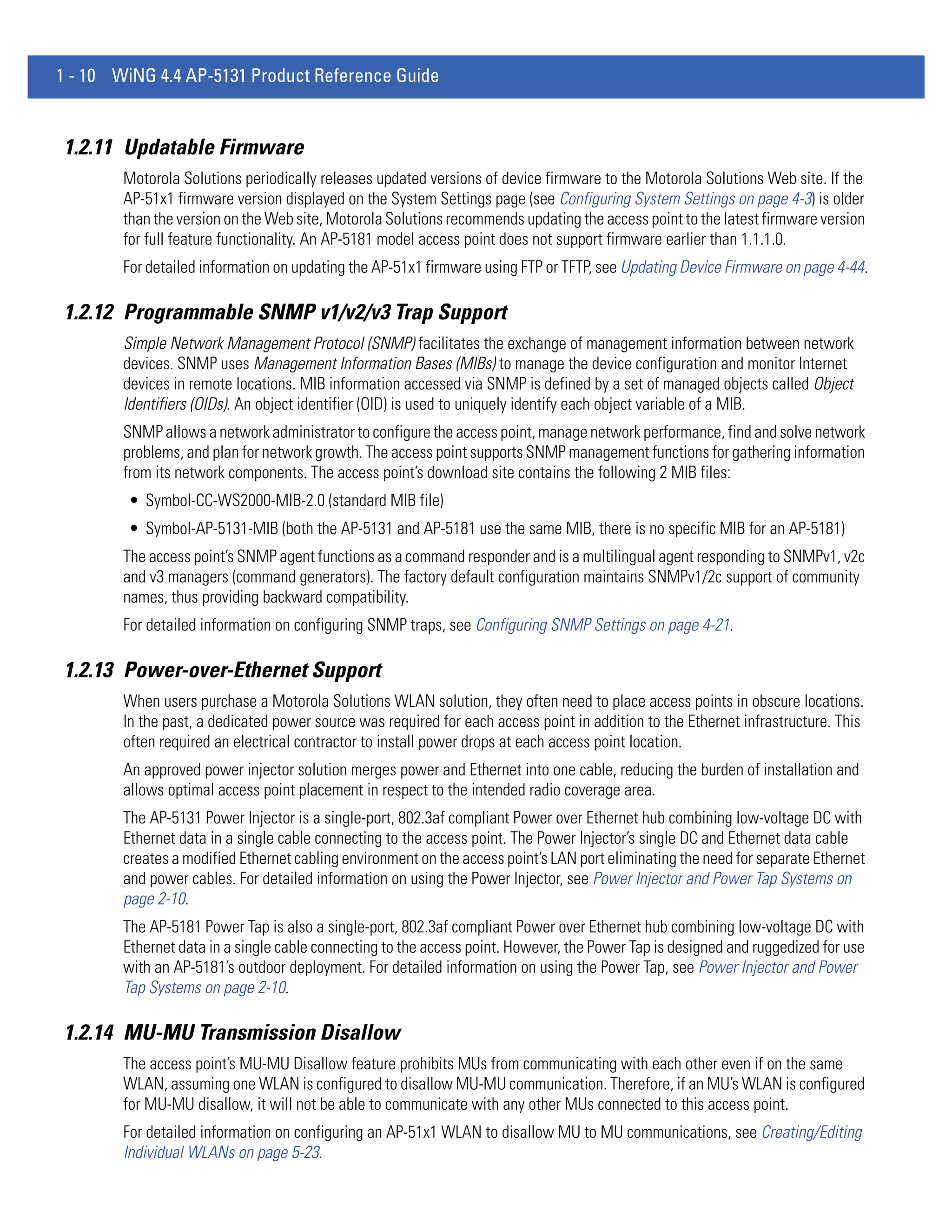
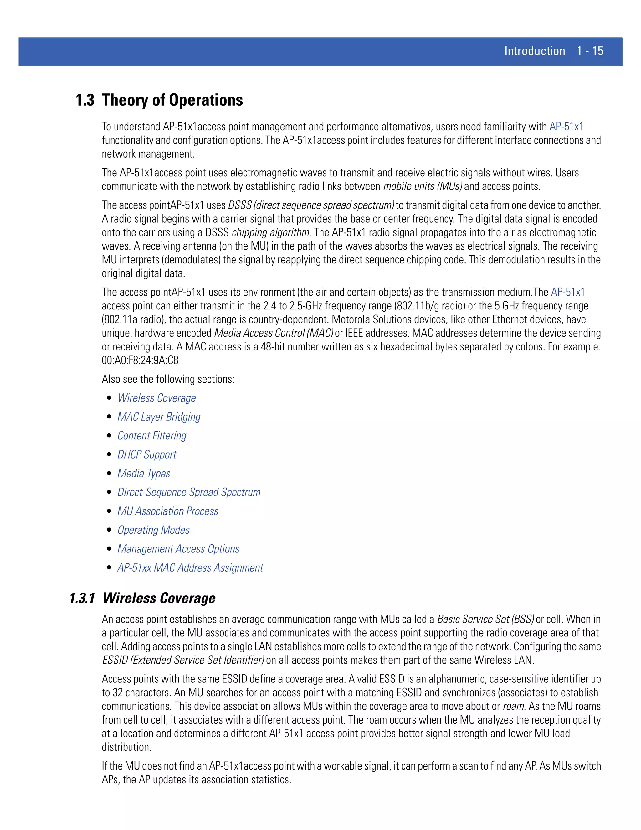
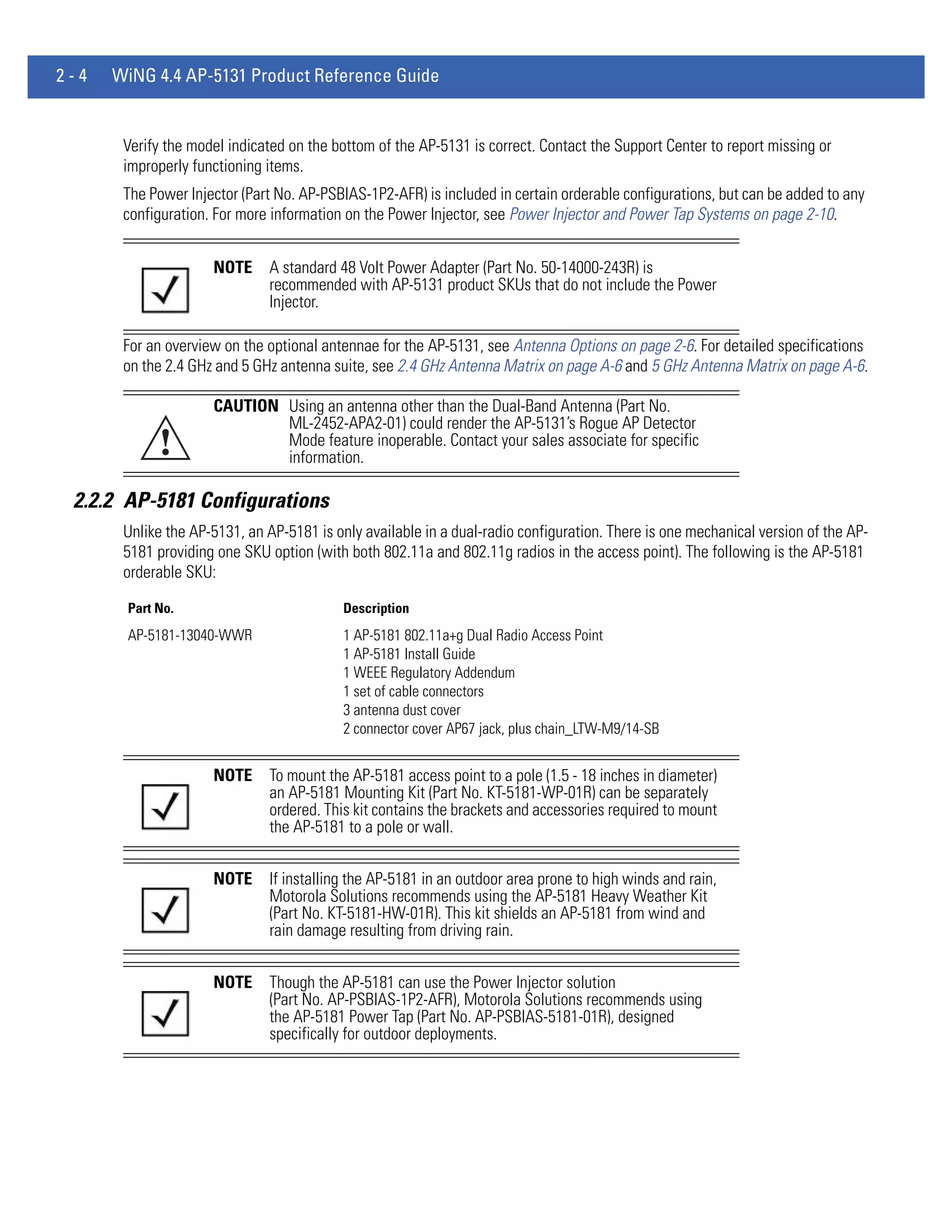
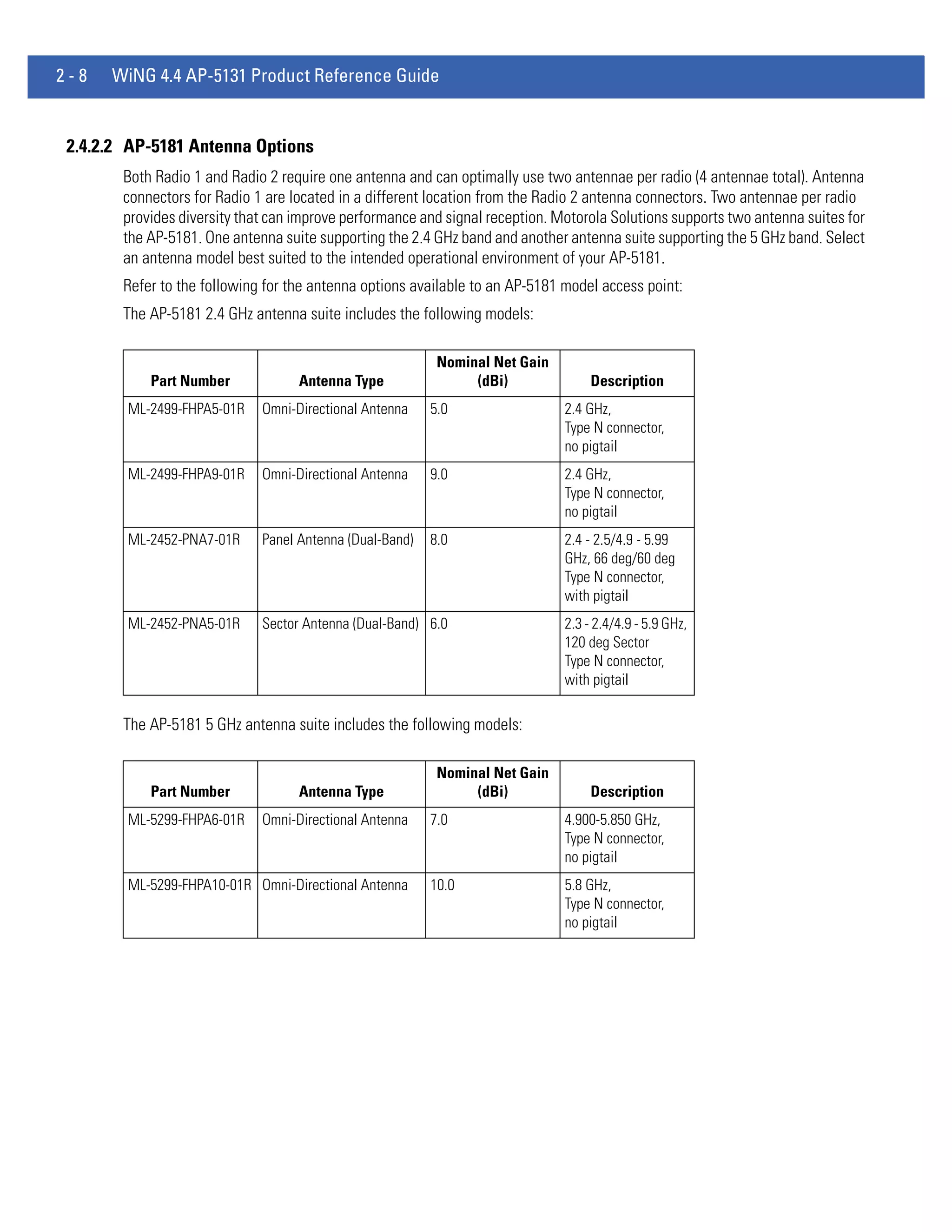
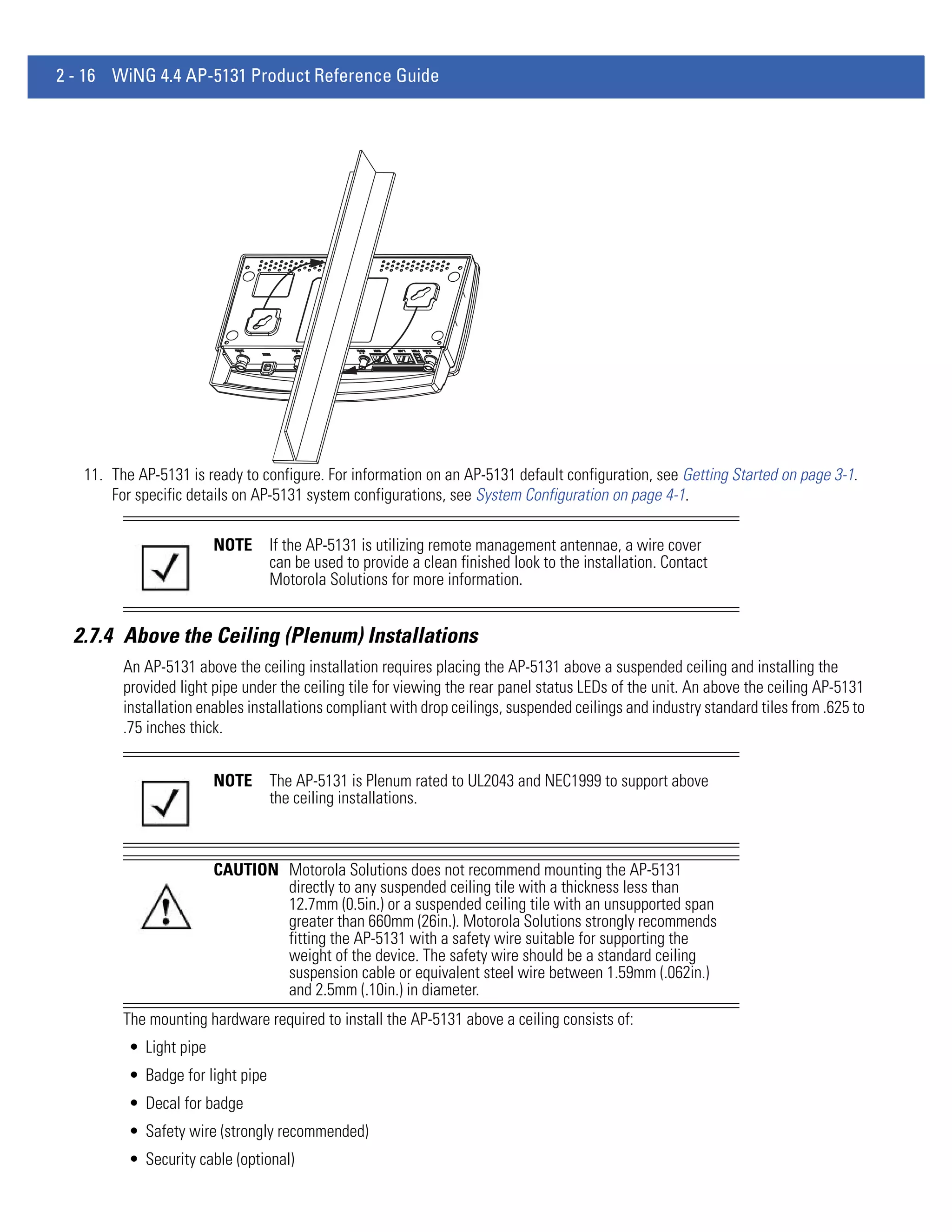
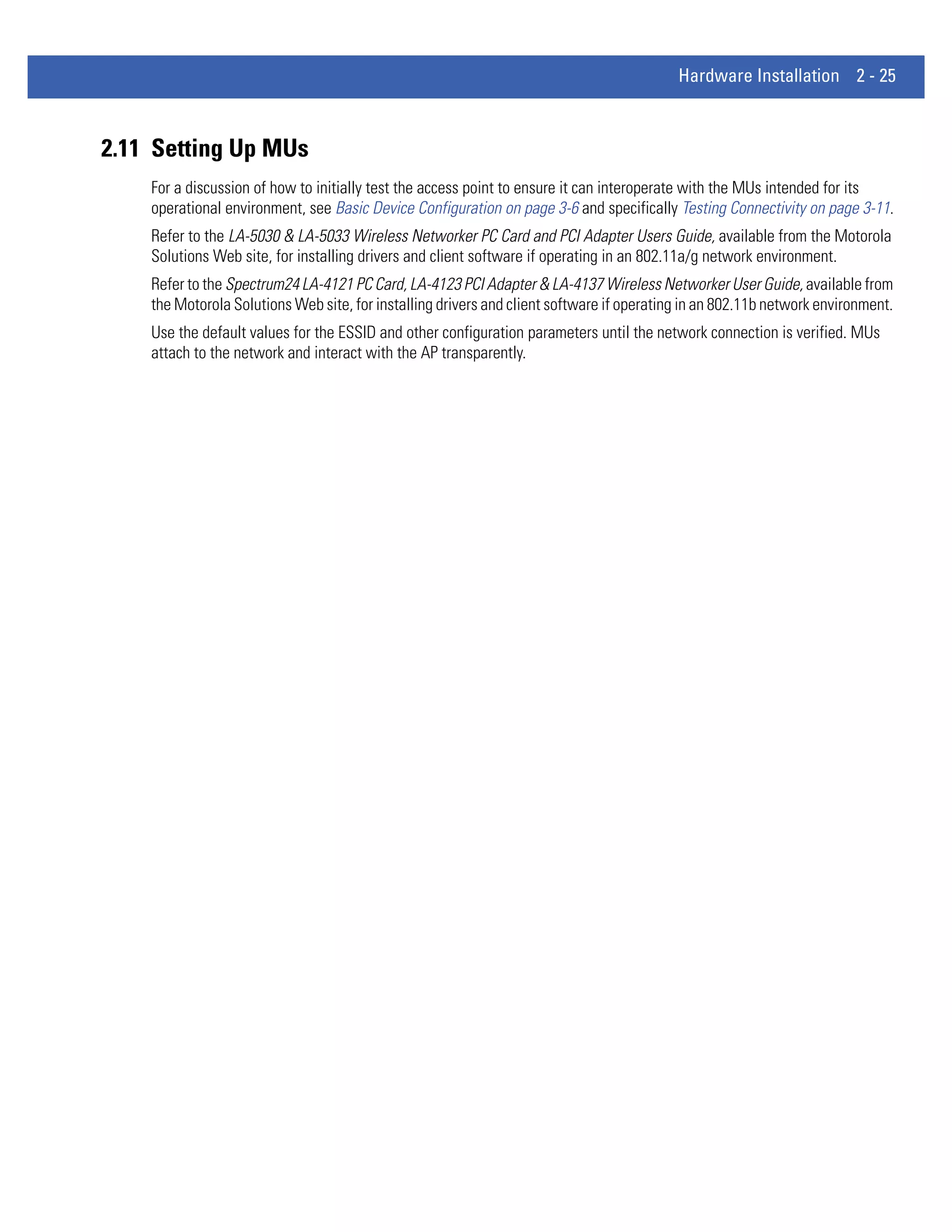
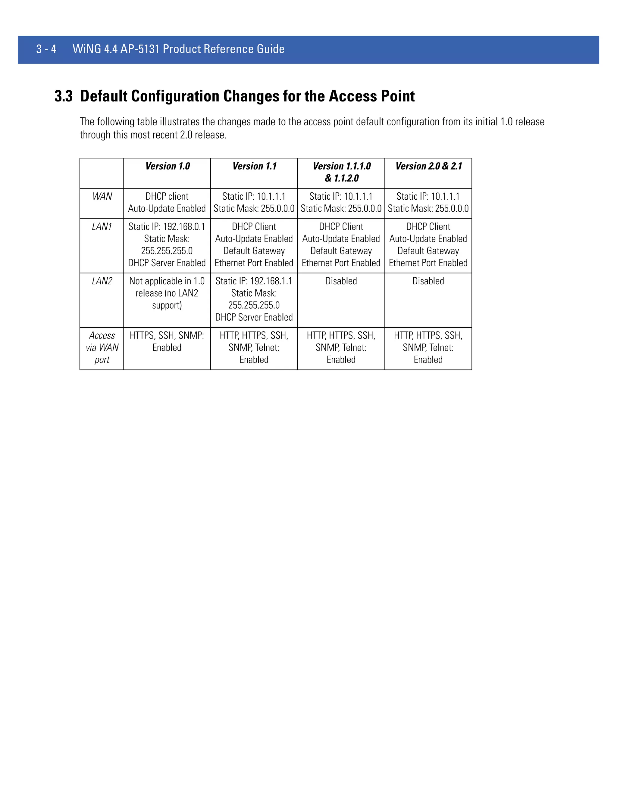
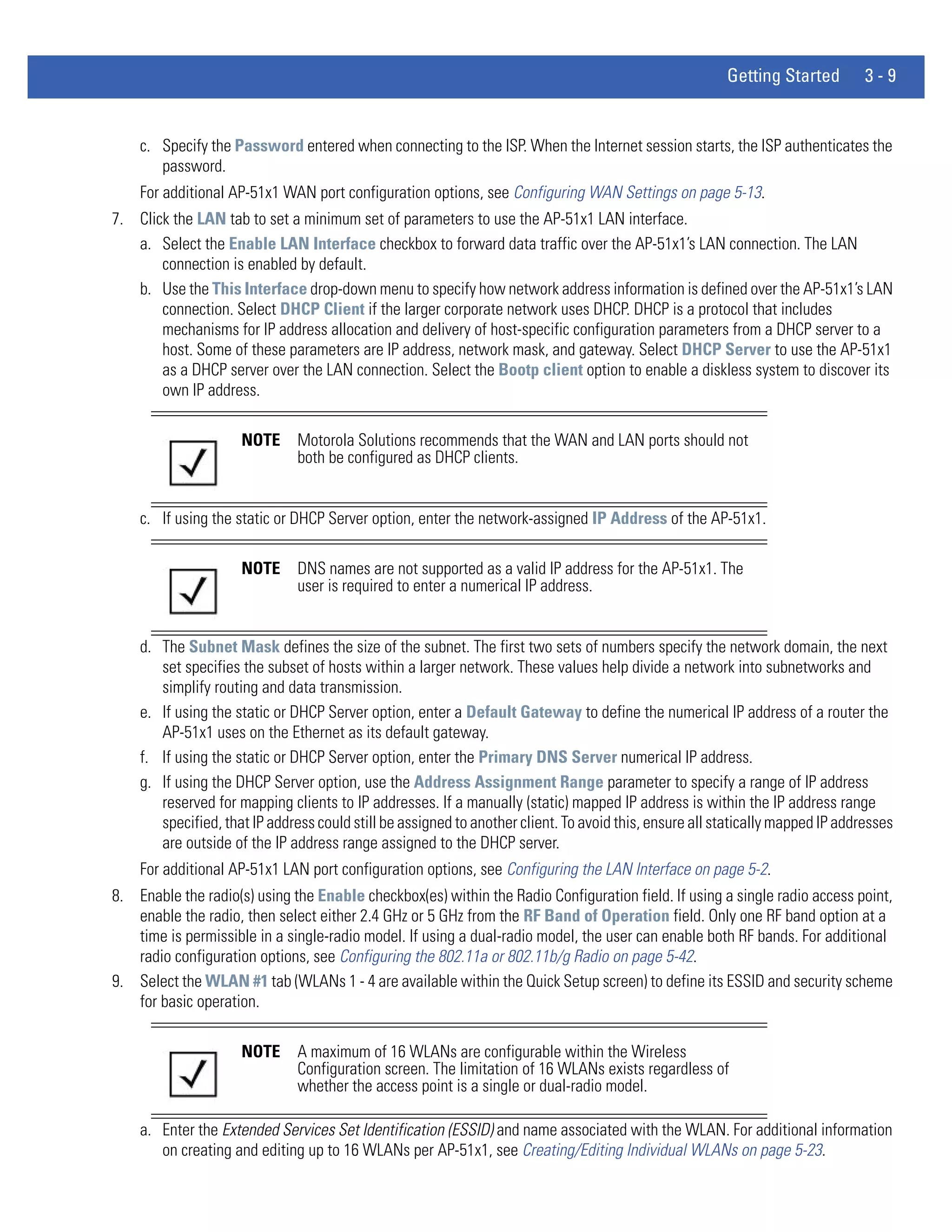
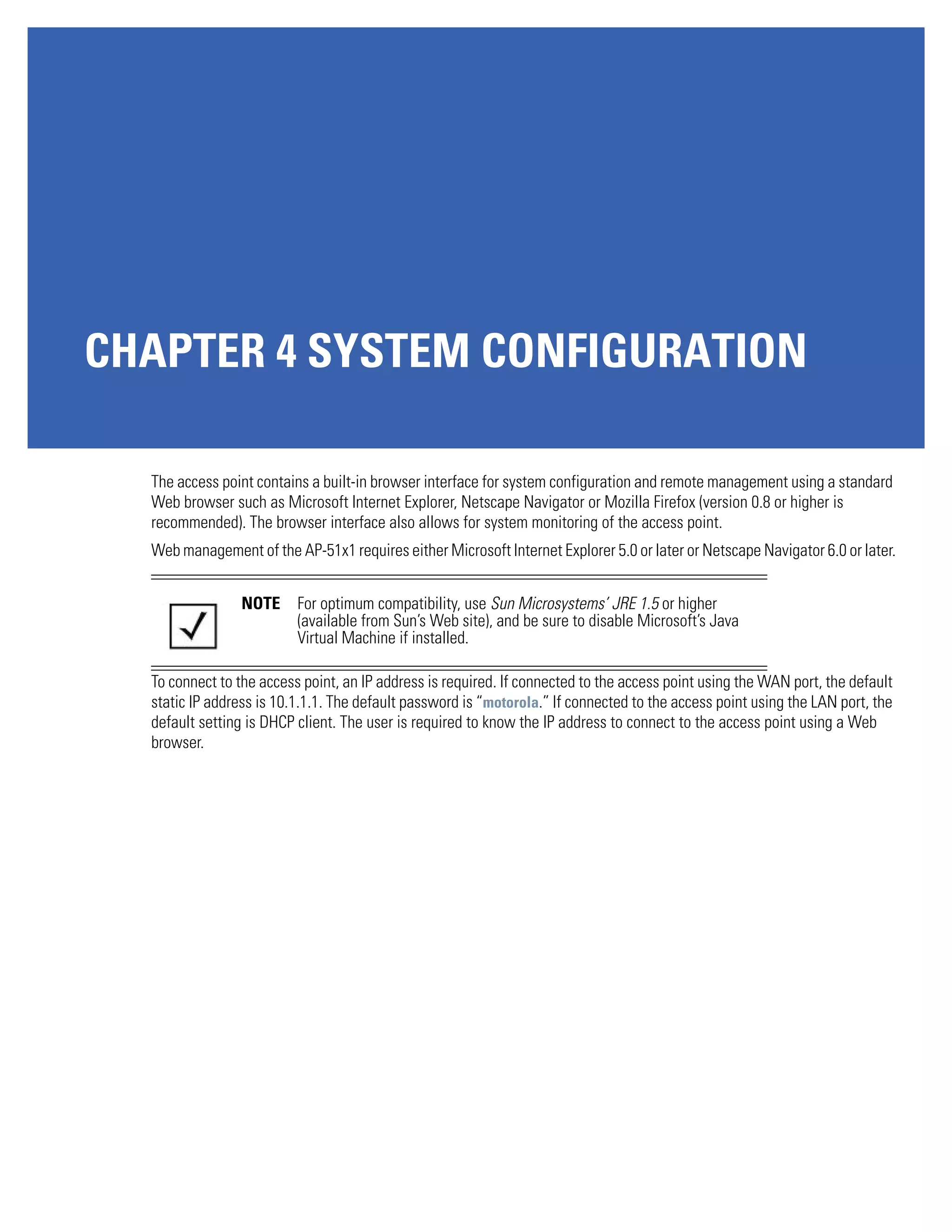
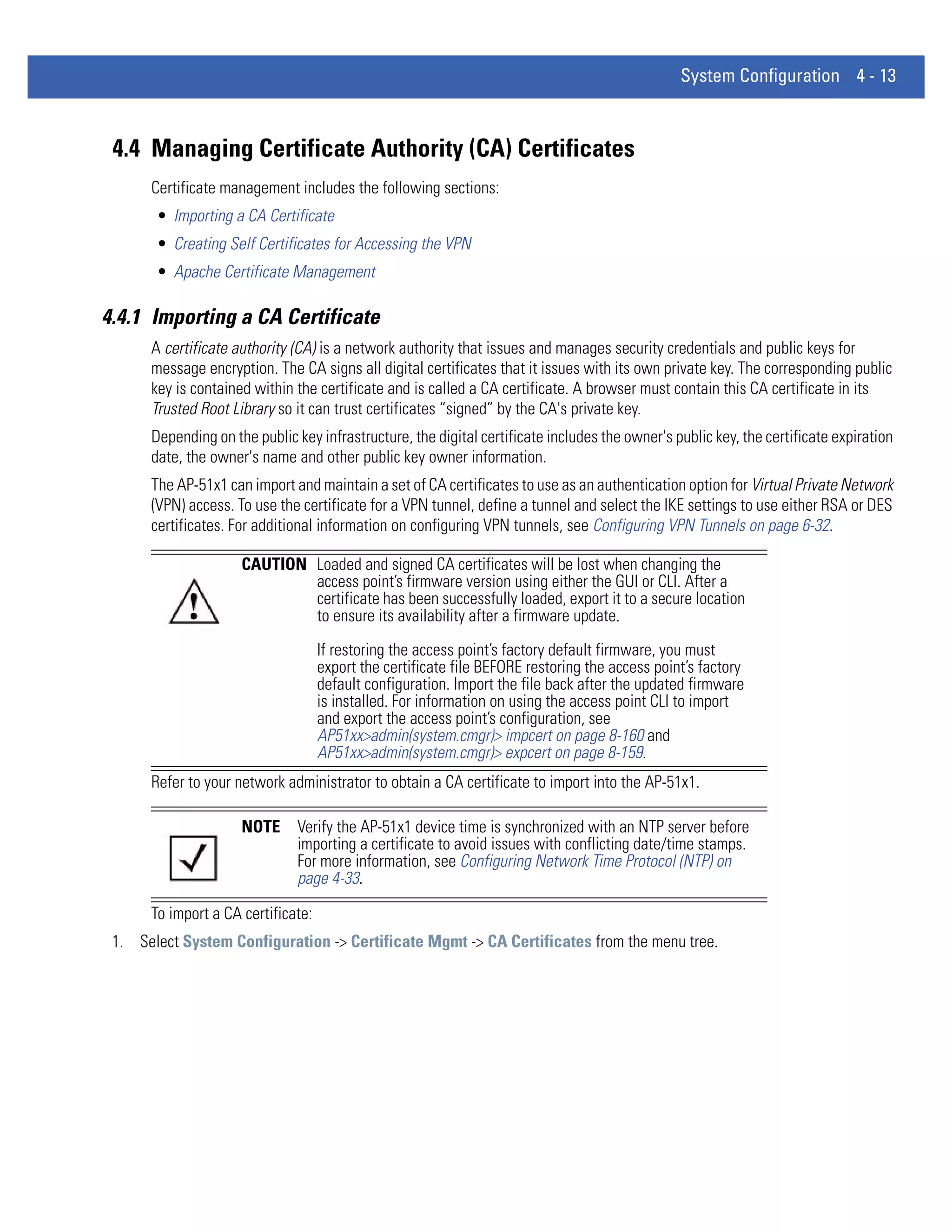
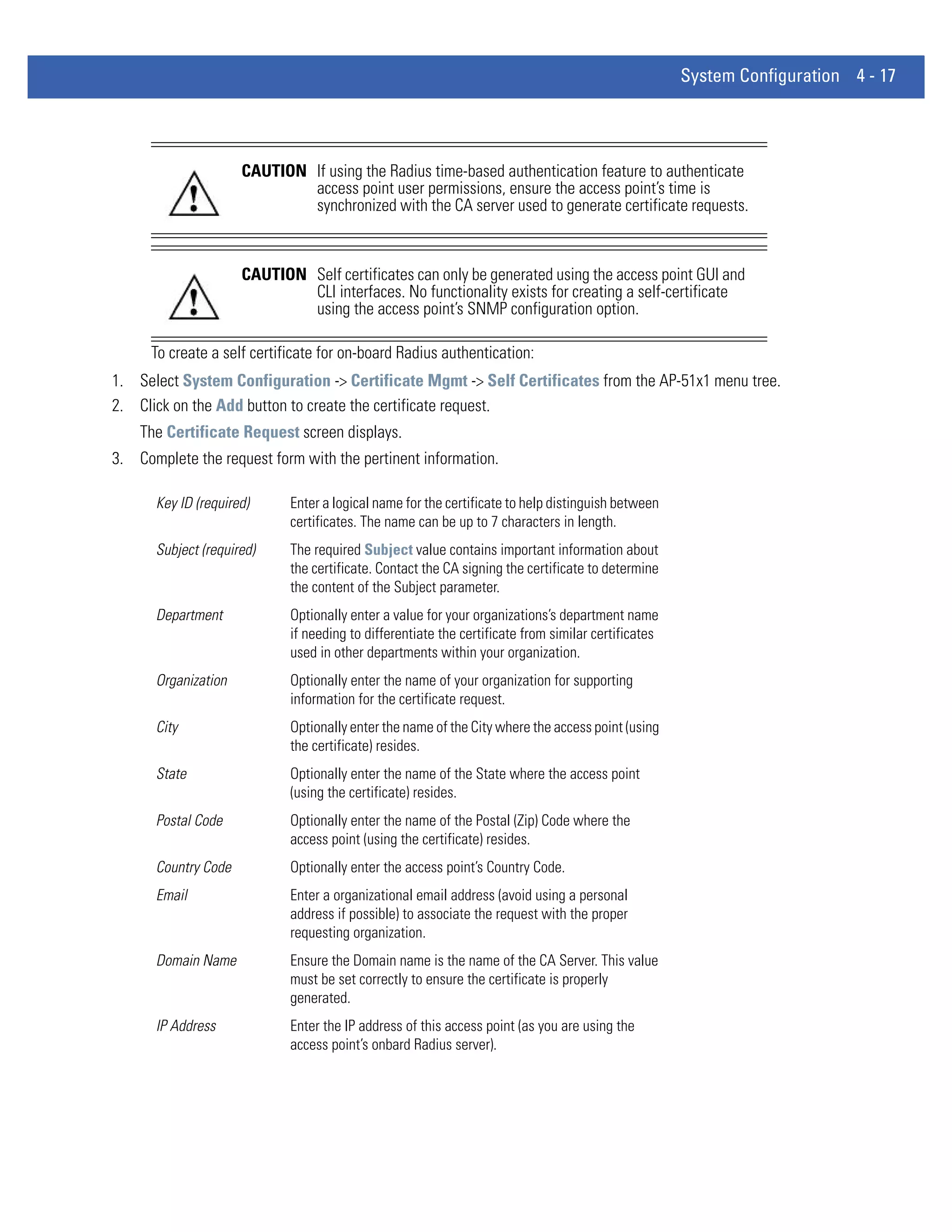
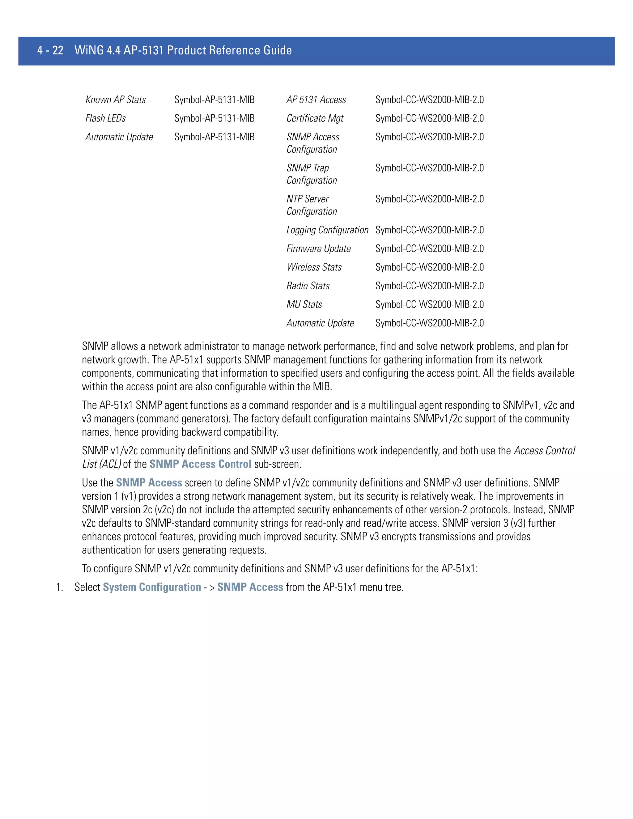
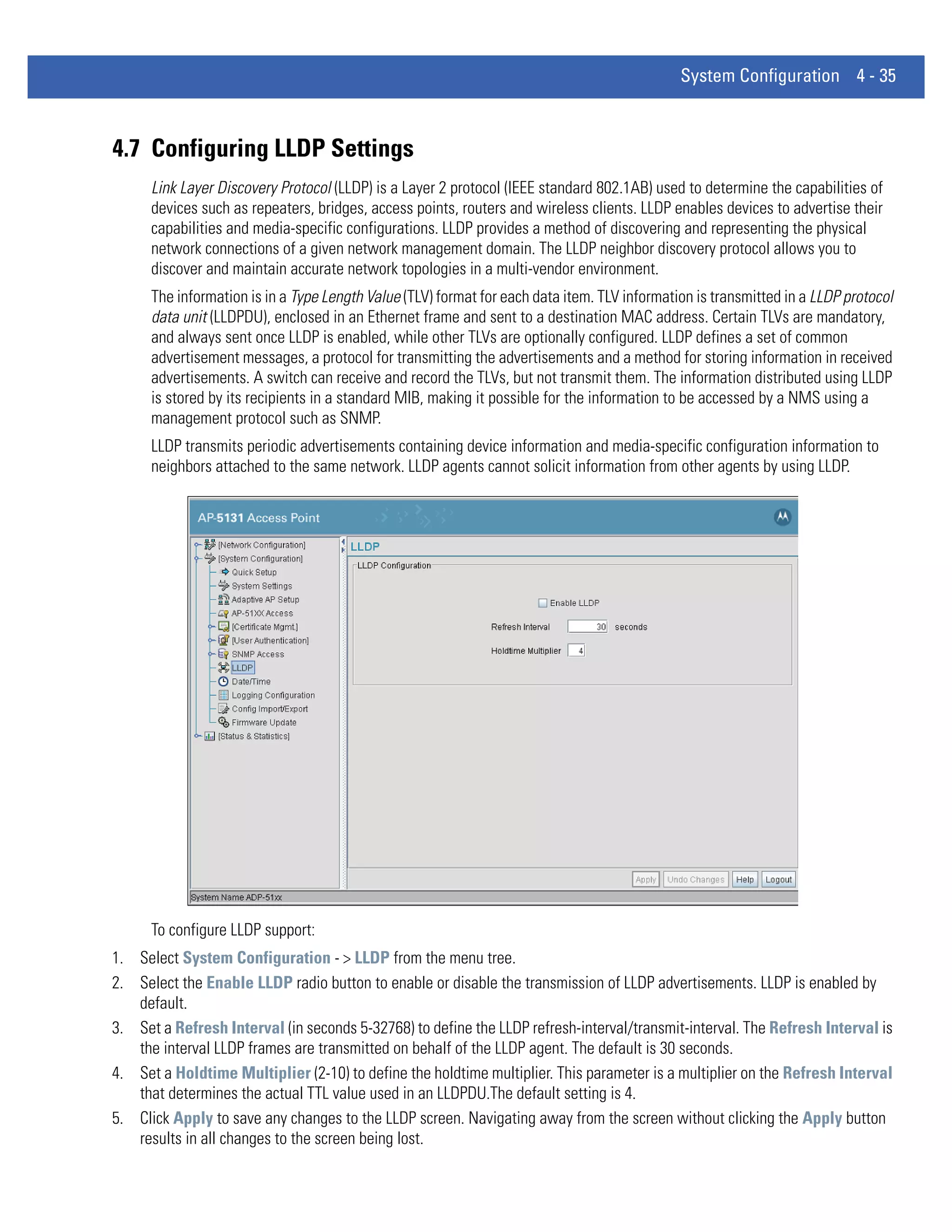
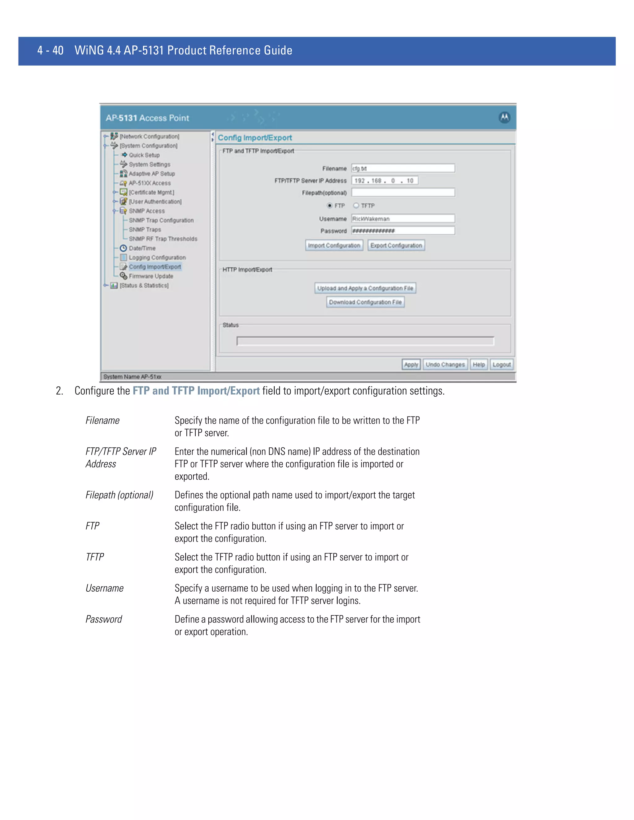
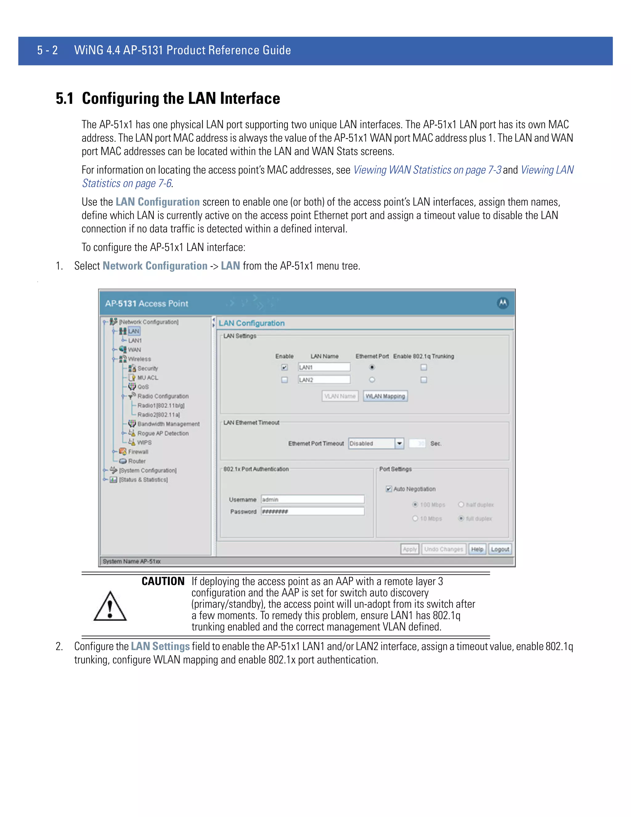
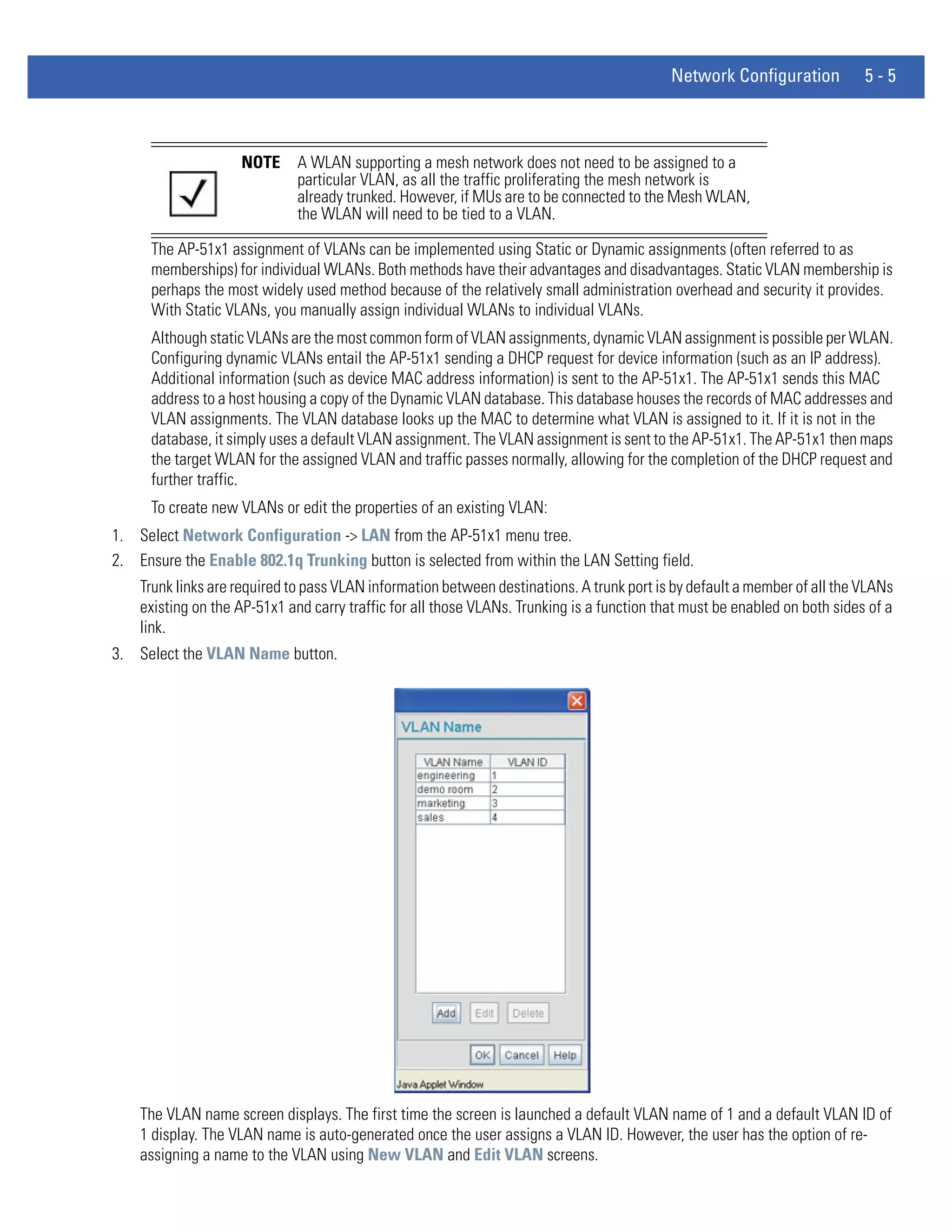
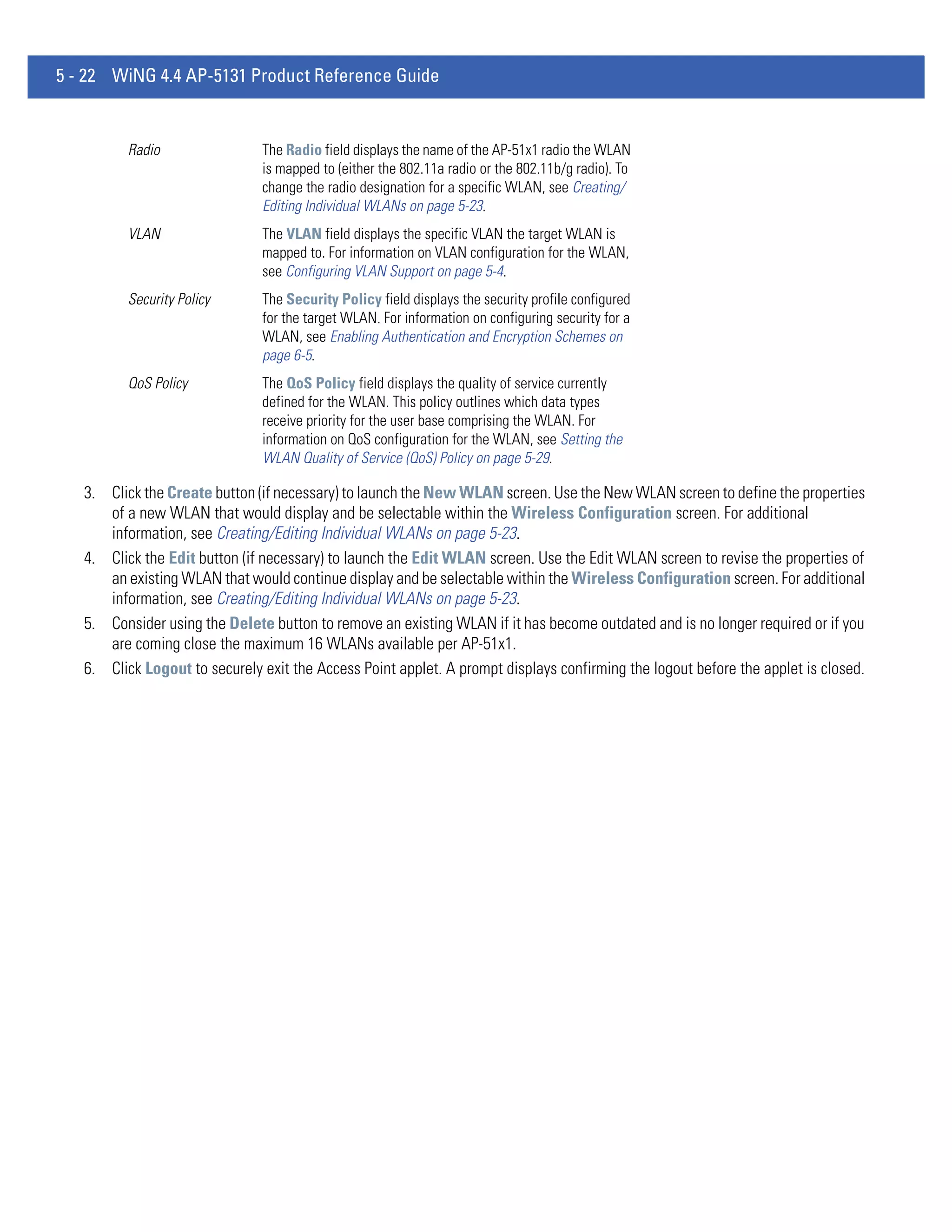
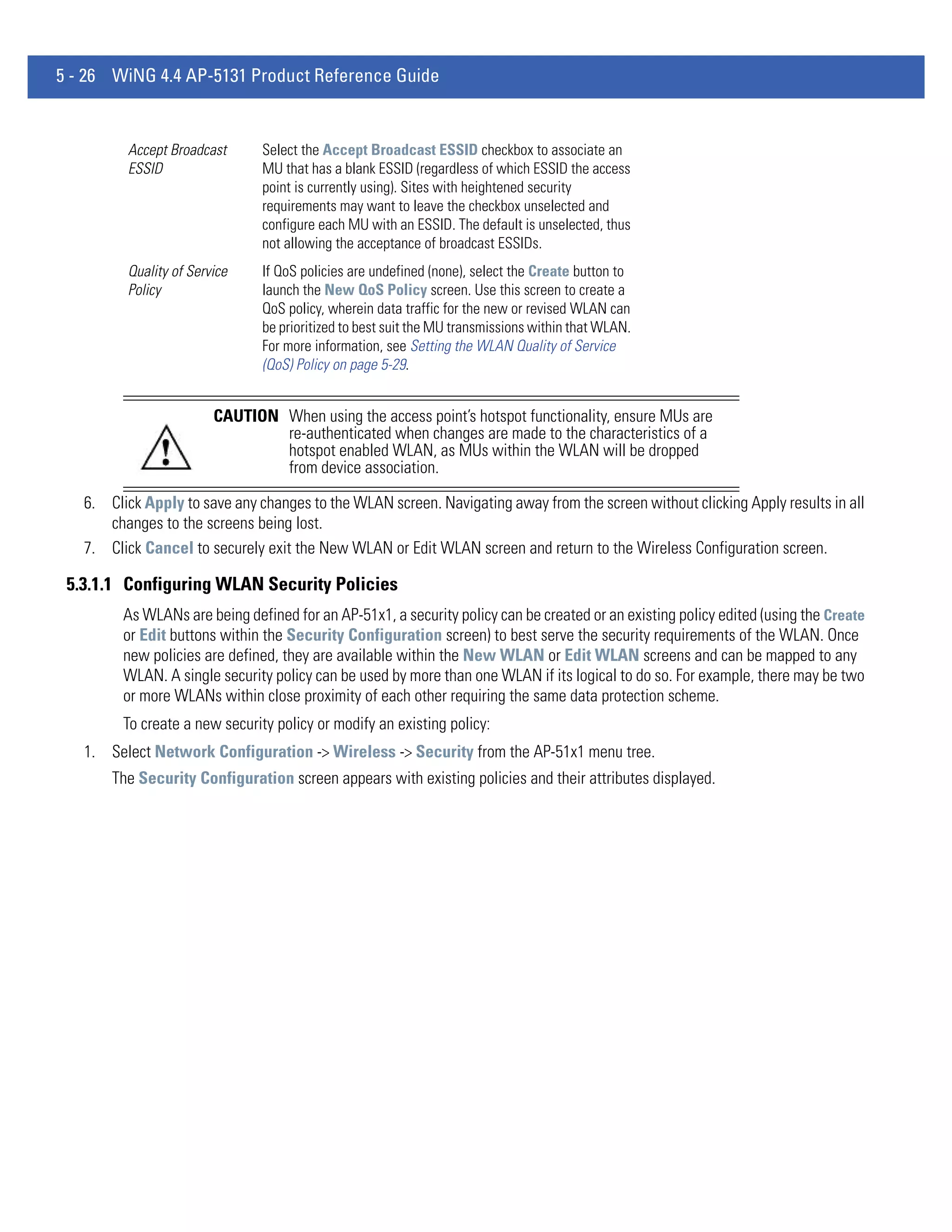
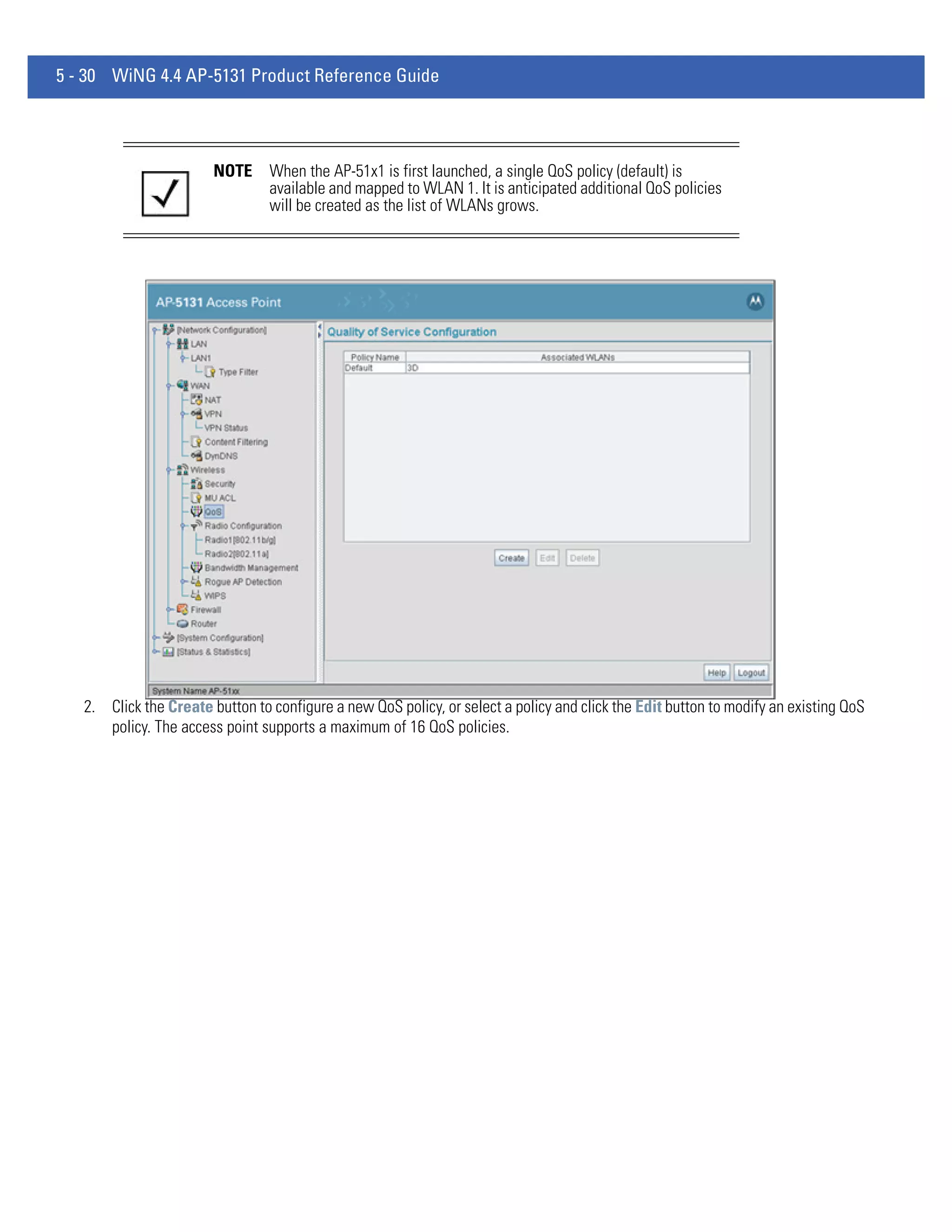
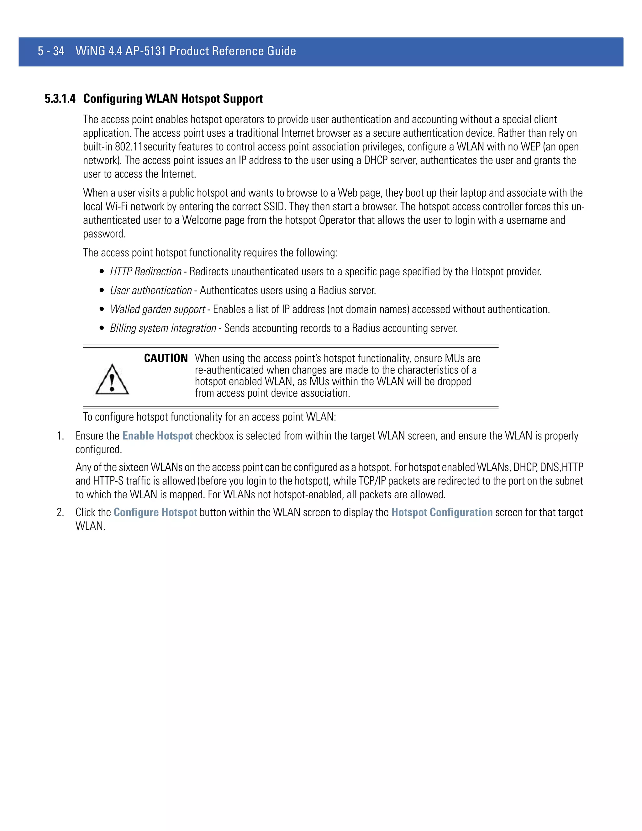
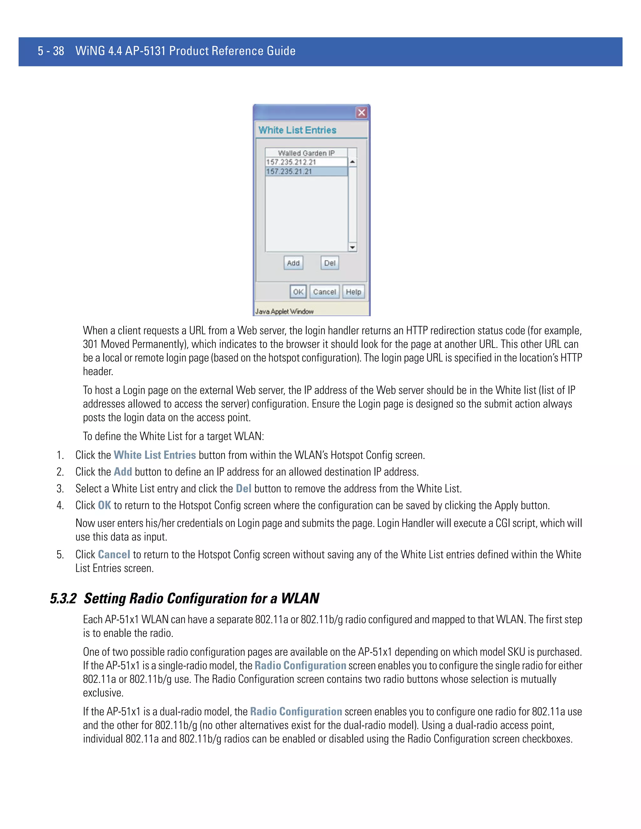
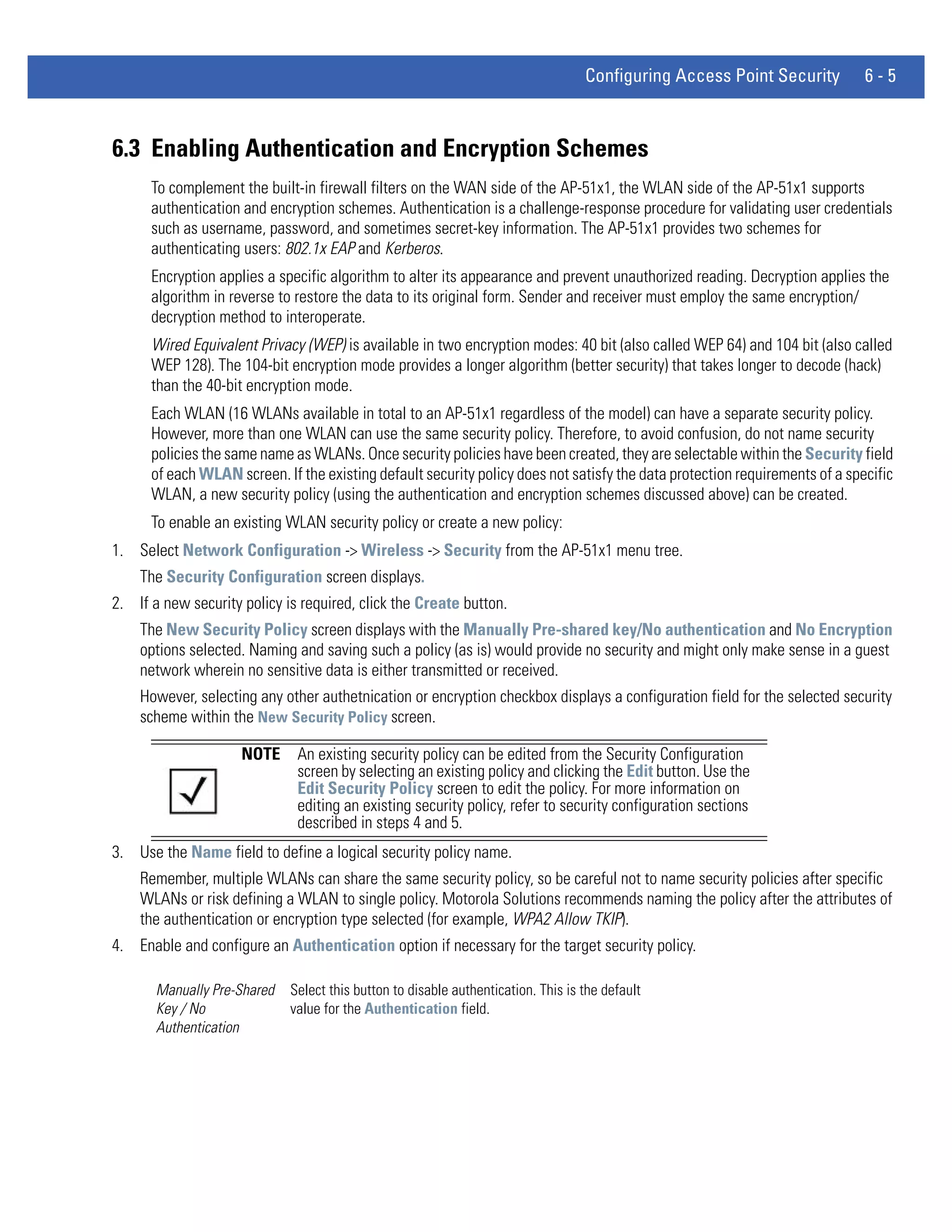
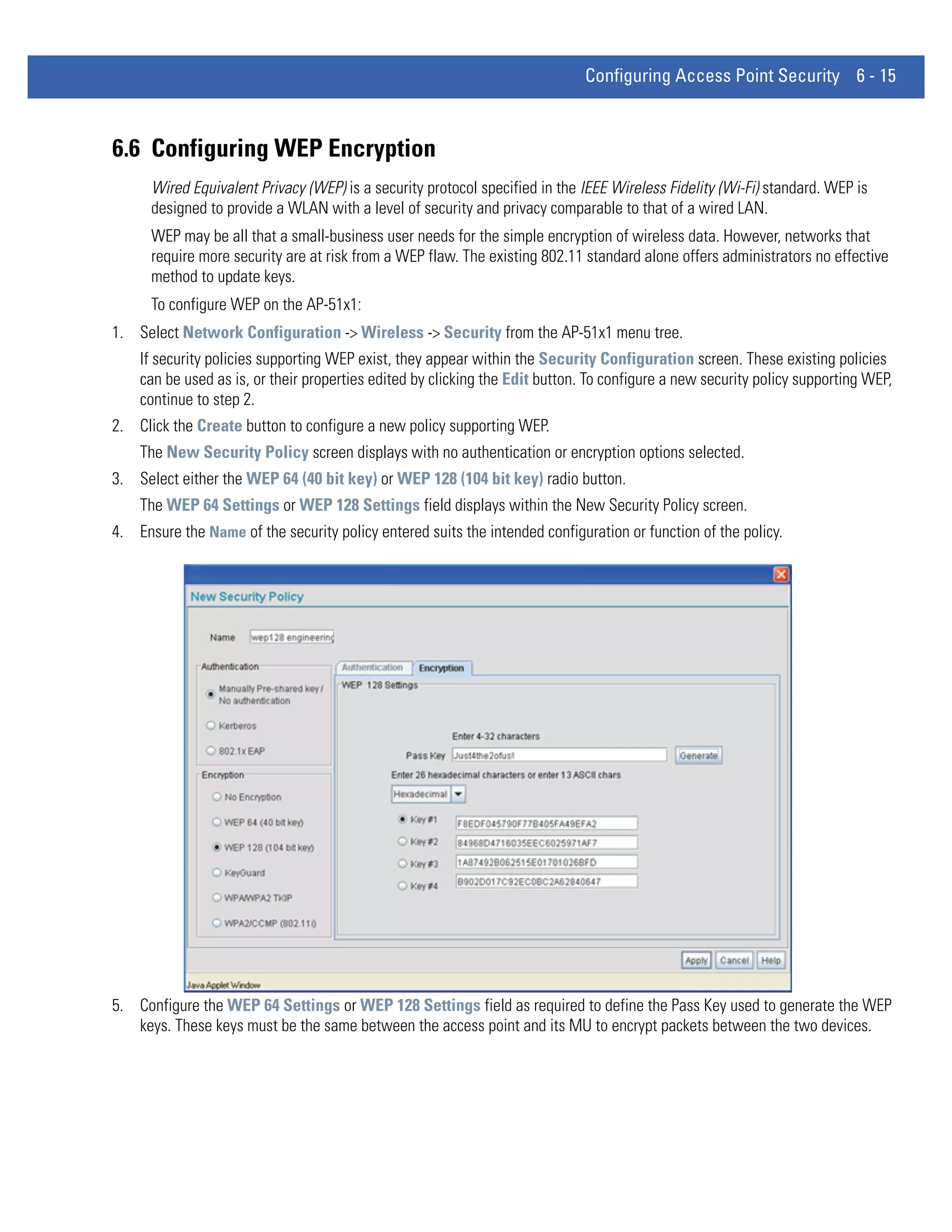
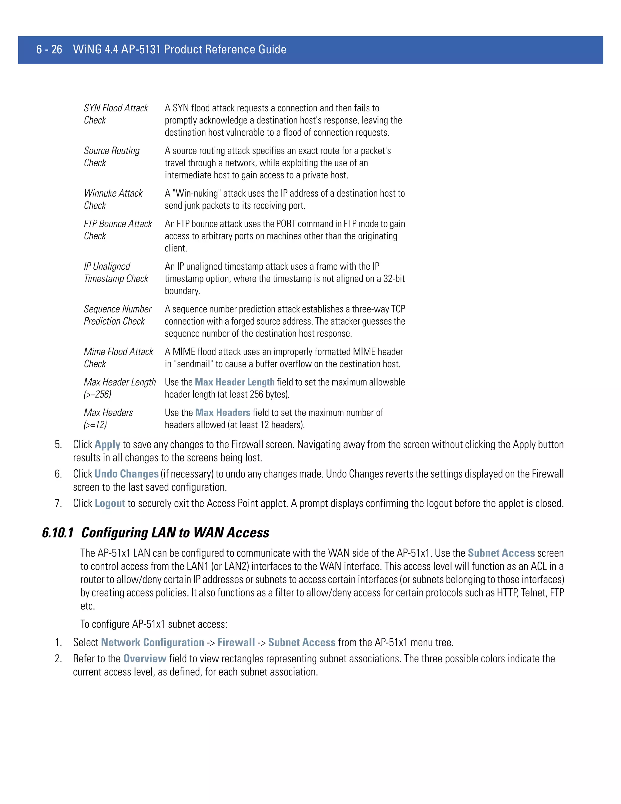
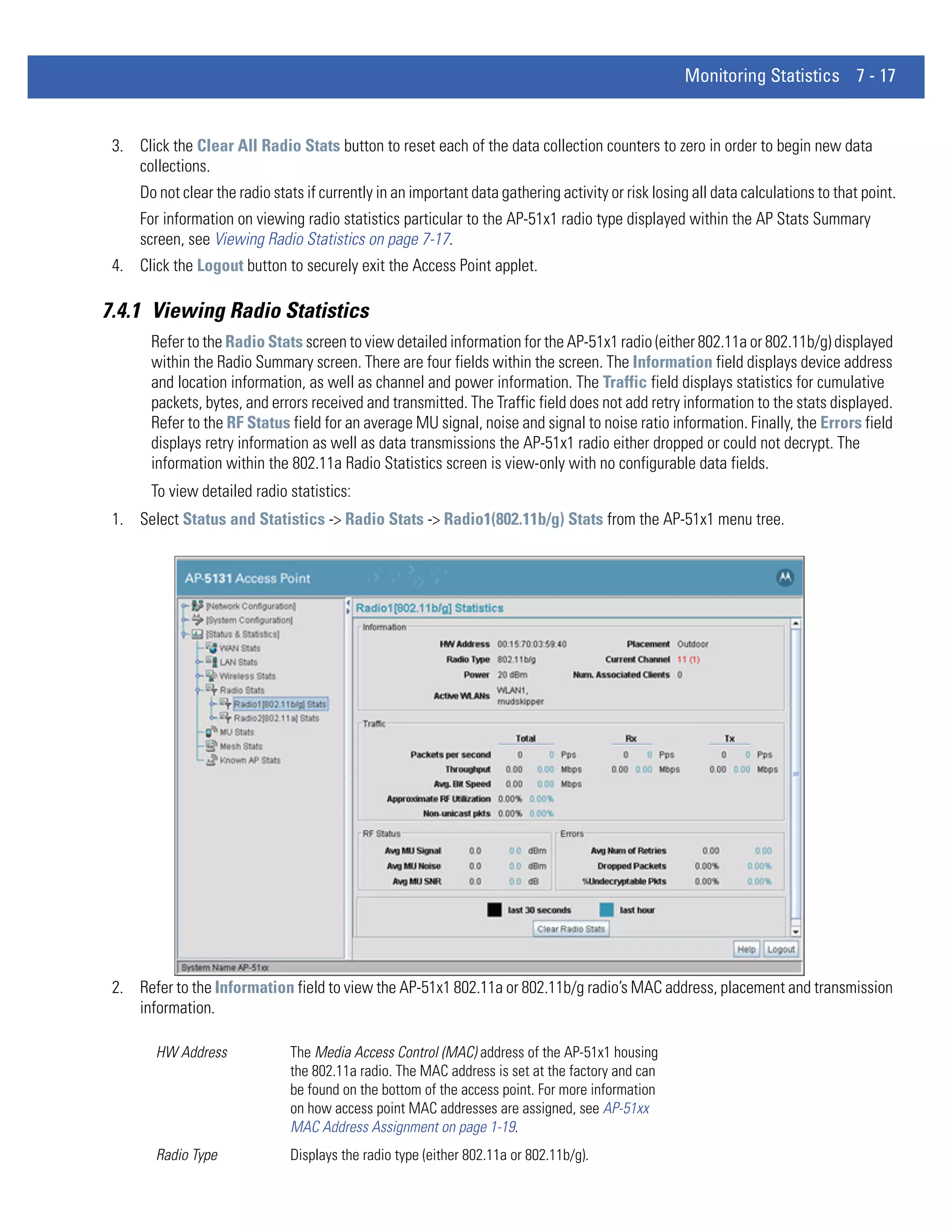
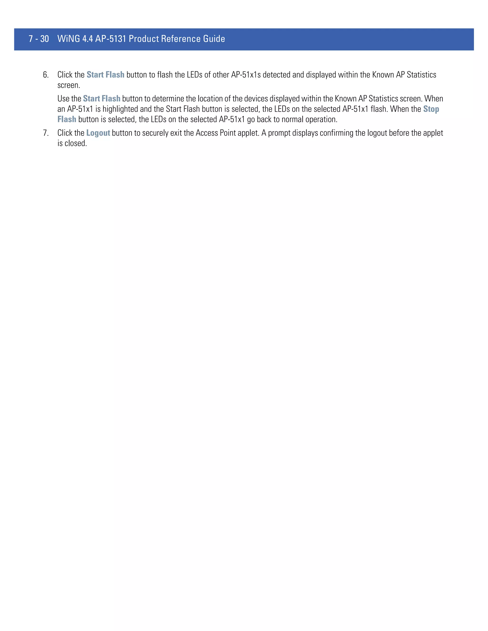
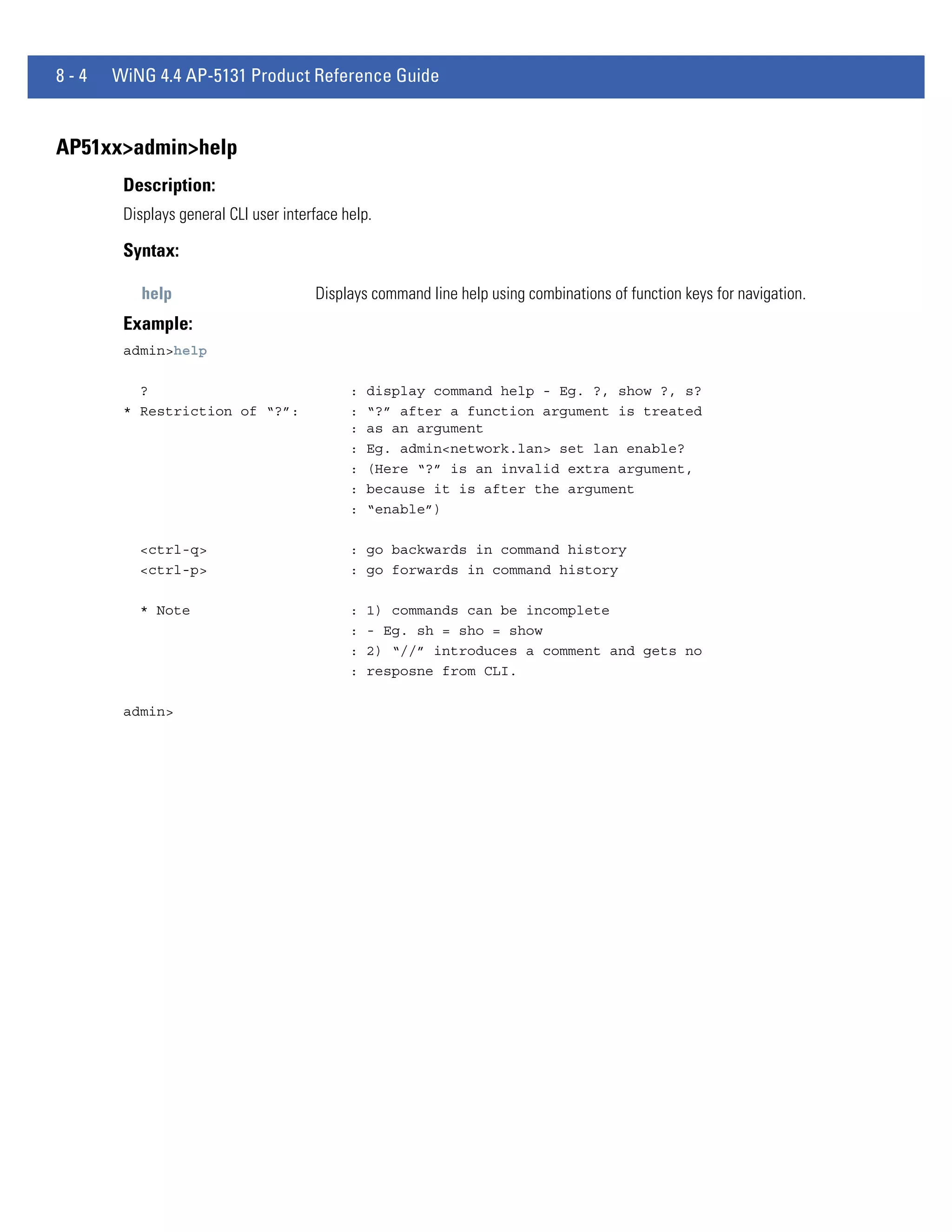
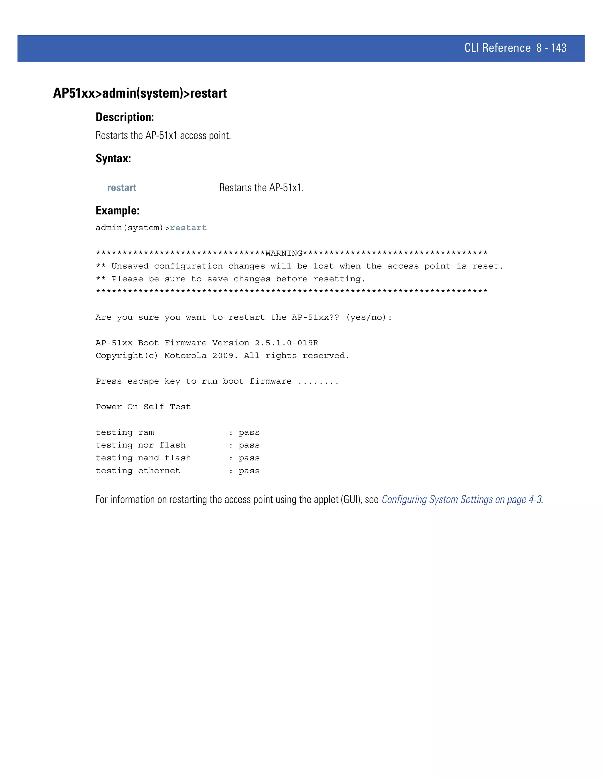
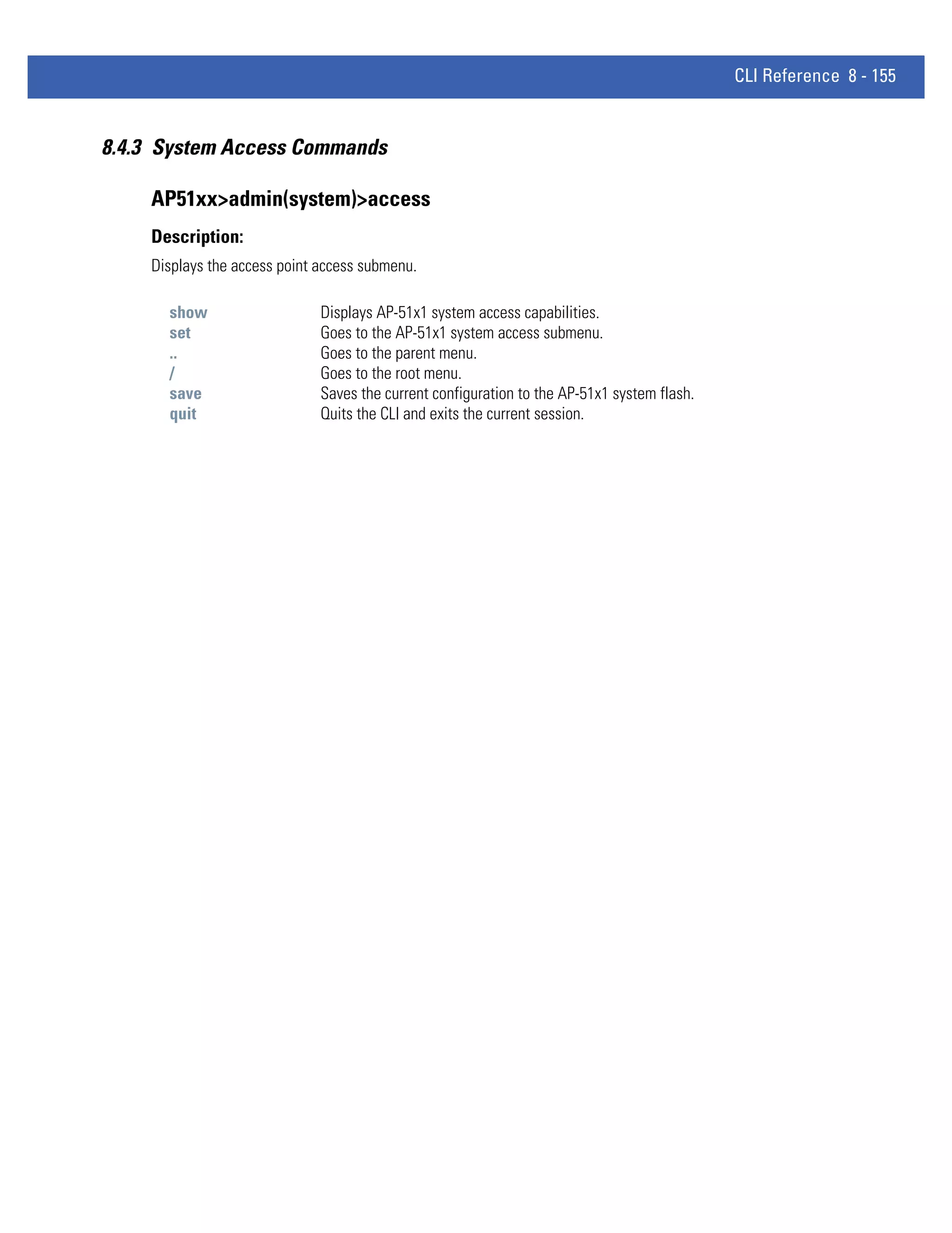
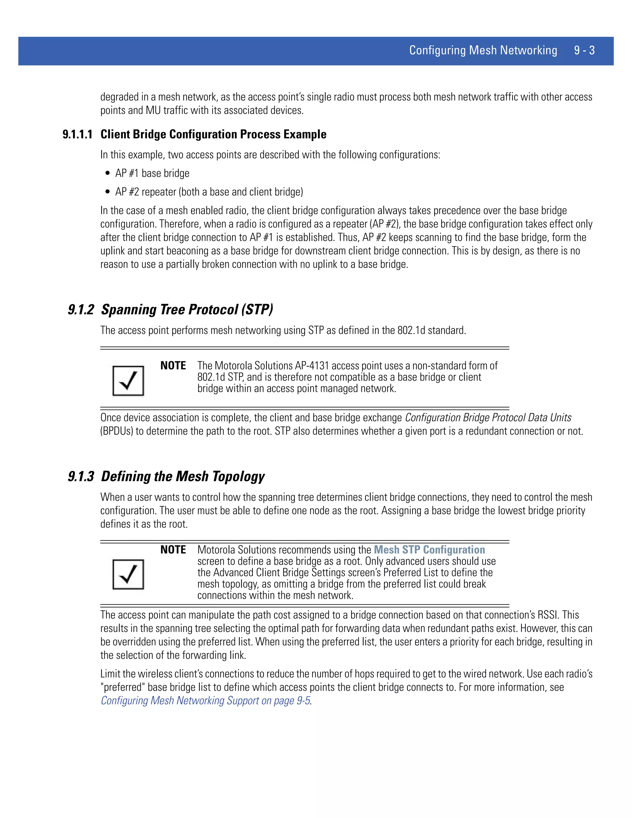
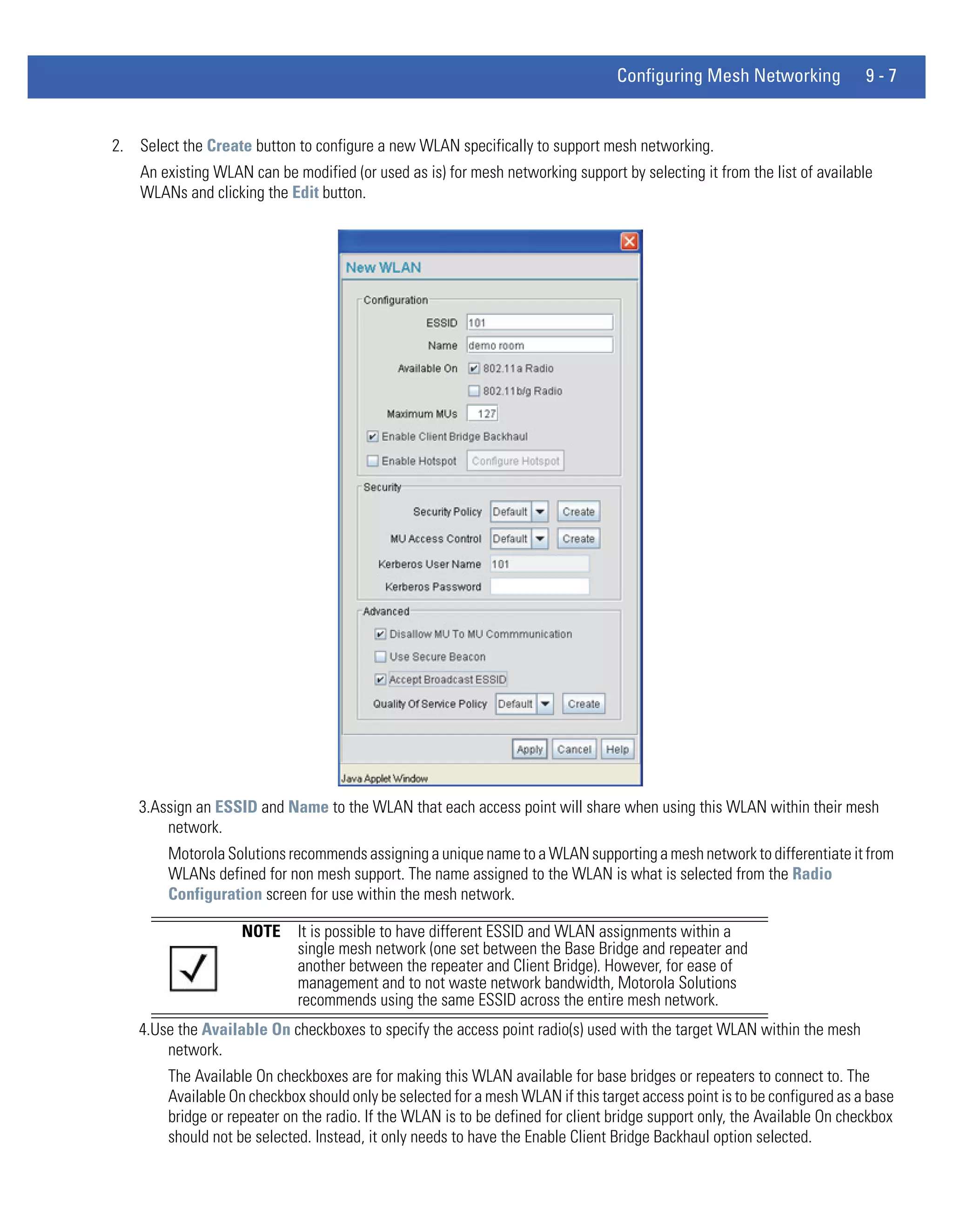
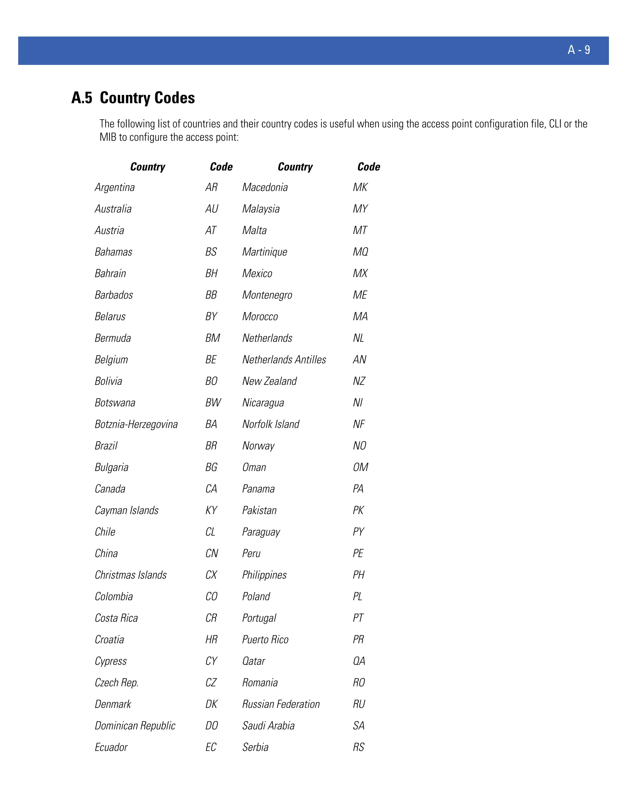
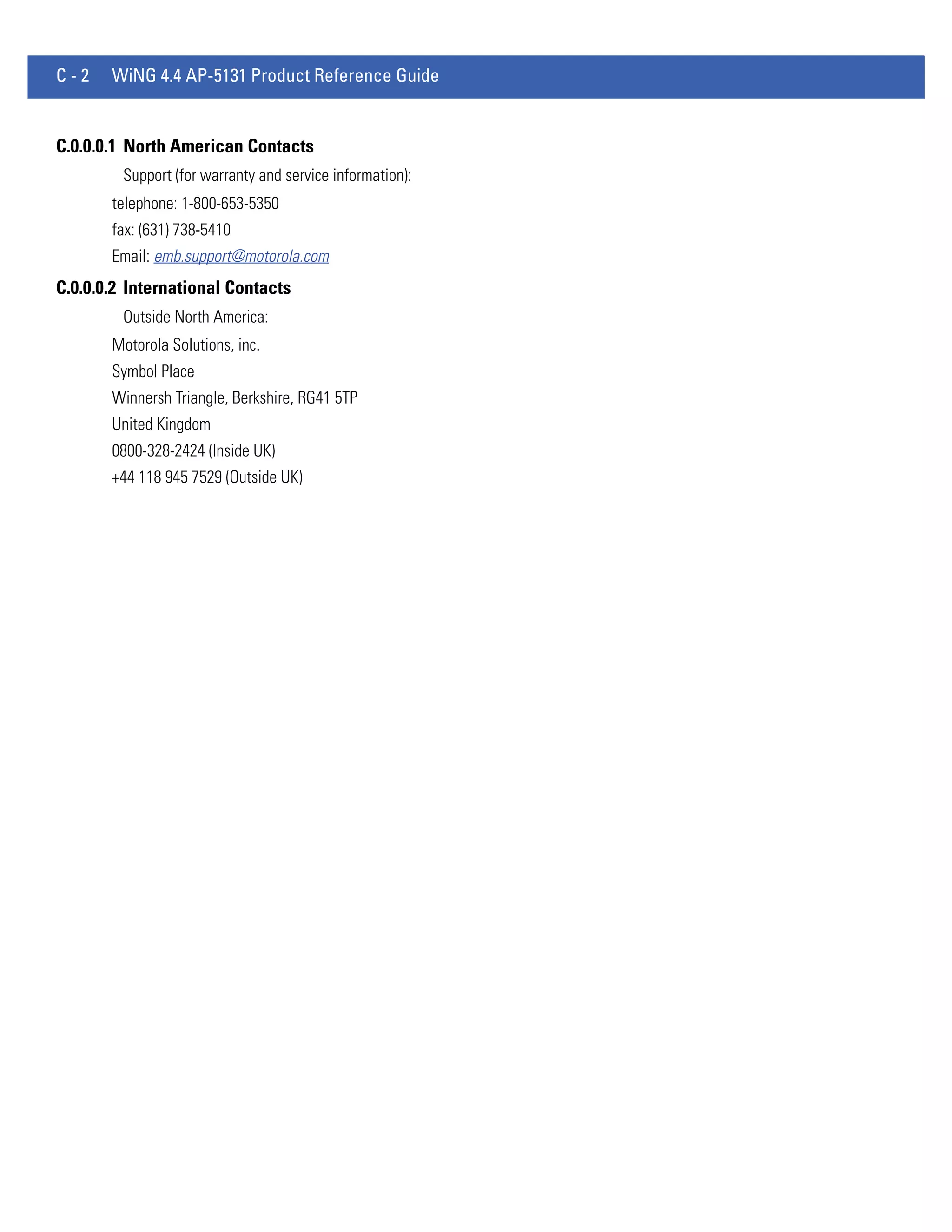
Status After executing an operation (by clicking any of the buttons in the
window), check the Status field for a progress indicator and
messages about the success or errors in executing the Import/
Export operation. Possible status messages include:
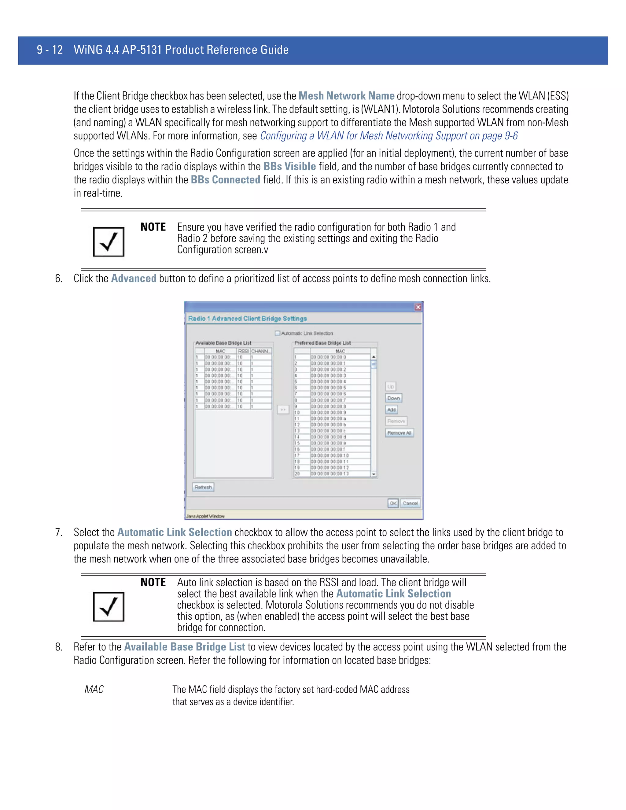
ambiguous input before marker: line <number >
unknown input before marker: line <number>
ignored input after marker: line <number>
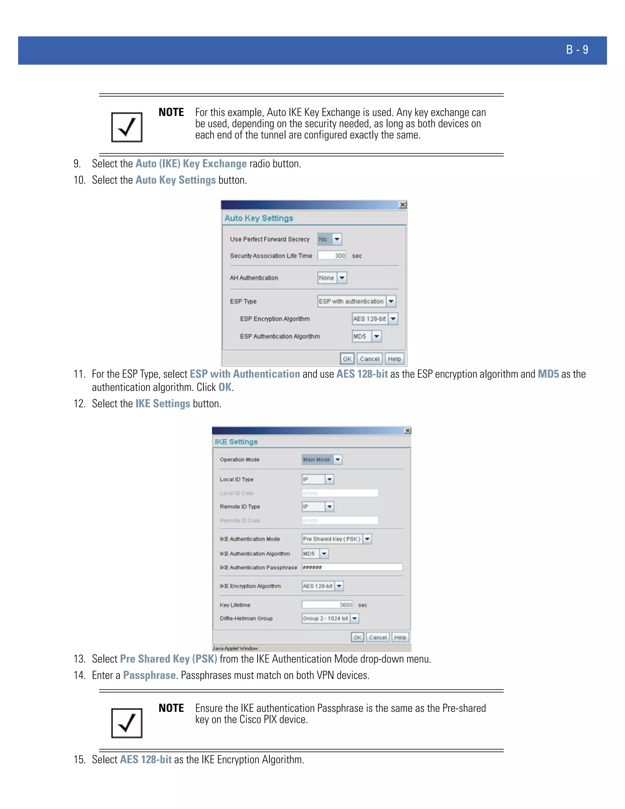
additional input required after marker: line <number>
invalid input length: line <number>
error reading input: line <number>
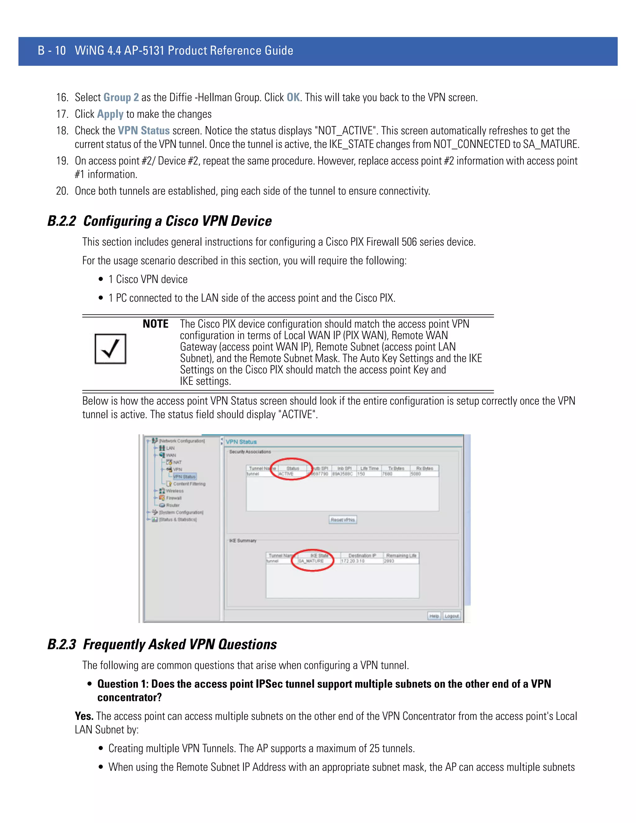
import file from incompatible hardware type: line <number>
[0] Import operation done
[1] Export operation done
[2] Import operation failed
[3] Export operation failed
[4] File transfer in progress
[5] File transfer failed
[6] File transfer done
Auto cfg update: Error in applying config
Auto cfg update: Error in getting config file
Auto cfg update: Aborting due to fw update failure
The <number> value appearing at the end of some messages
relates to the line of the configuration file where an error or
ambiguous input was detected.
CAUTION If errors occur when importing the configuration file, a parsing
message displays defining the line number where the error occurred.
The configuration is still imported, except for the error. Consequently,
it is possible to import an invalid configuration. The user is required to
fix the problem and repeat the import operation until an error-free
import takes place.
NOTE Motorola Solutions recommends importing configuration files using the
CLI. If errors occur during the import process, they display all at once and
are easier to troubleshoot. The access point GUI displays errors one at a
time, and troubleshooting can be a more time-consuming process.
NOTE When importing the configuration, a xxxxxbytes loaded status message
indicates the file was downloaded successfully. An Incompatible
Hardware Type Error message indicates the configuration was not applied
due to a hardware compatibility issue between the importing and
exporting devices.
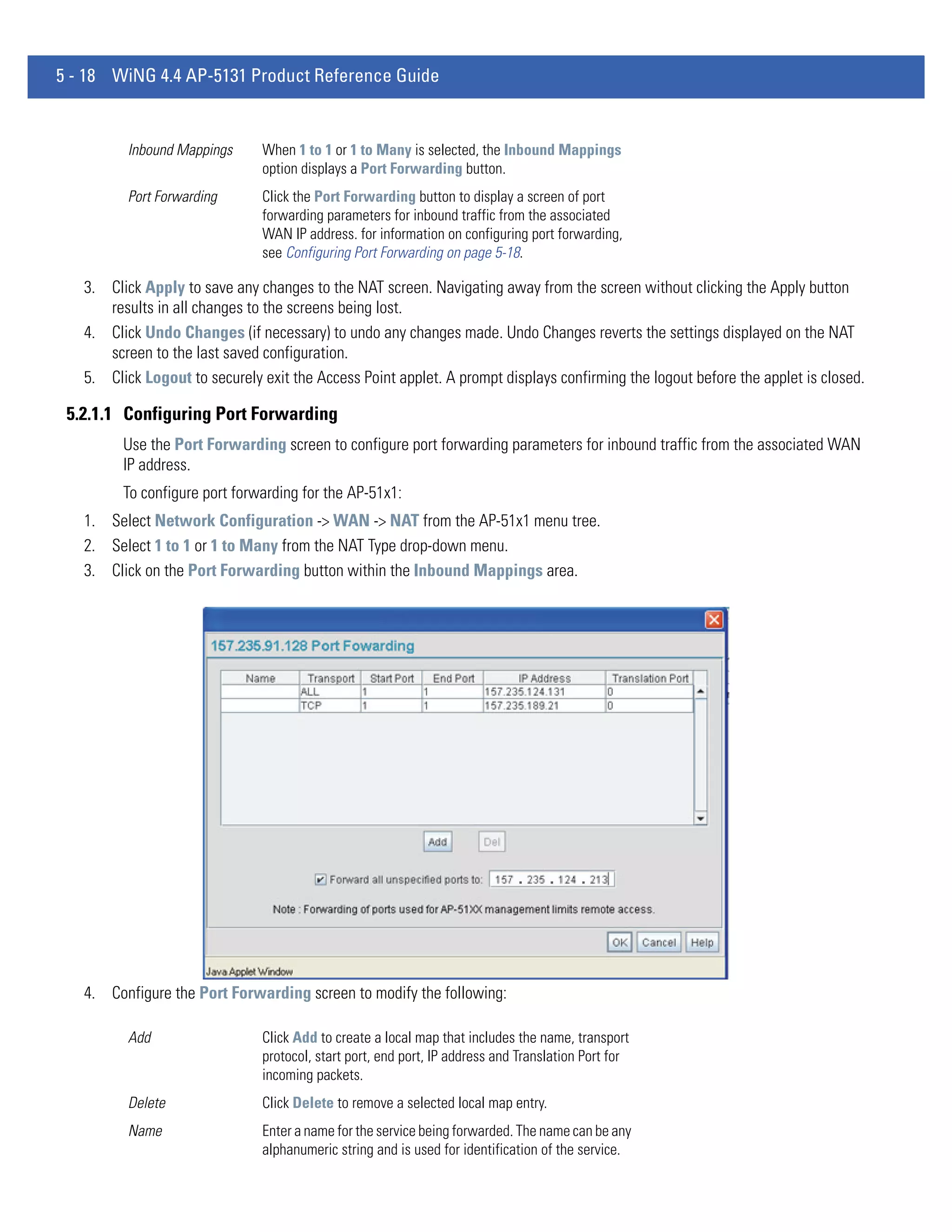
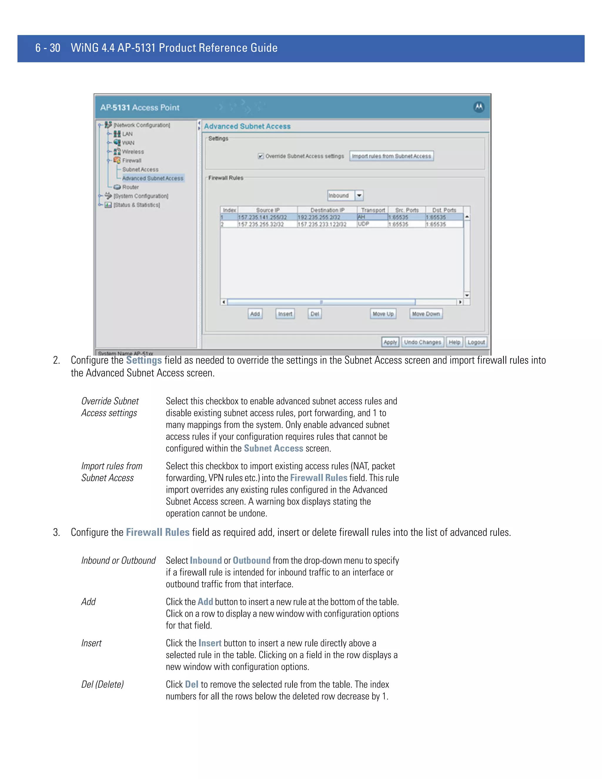
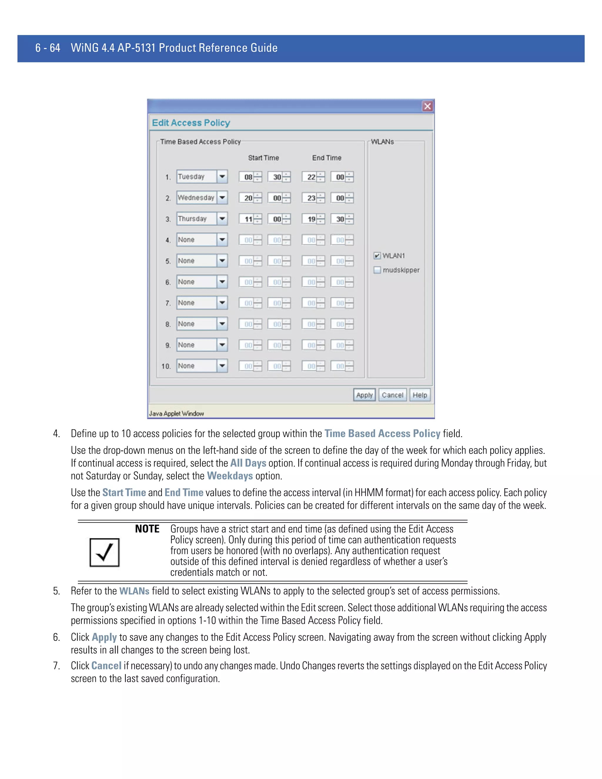
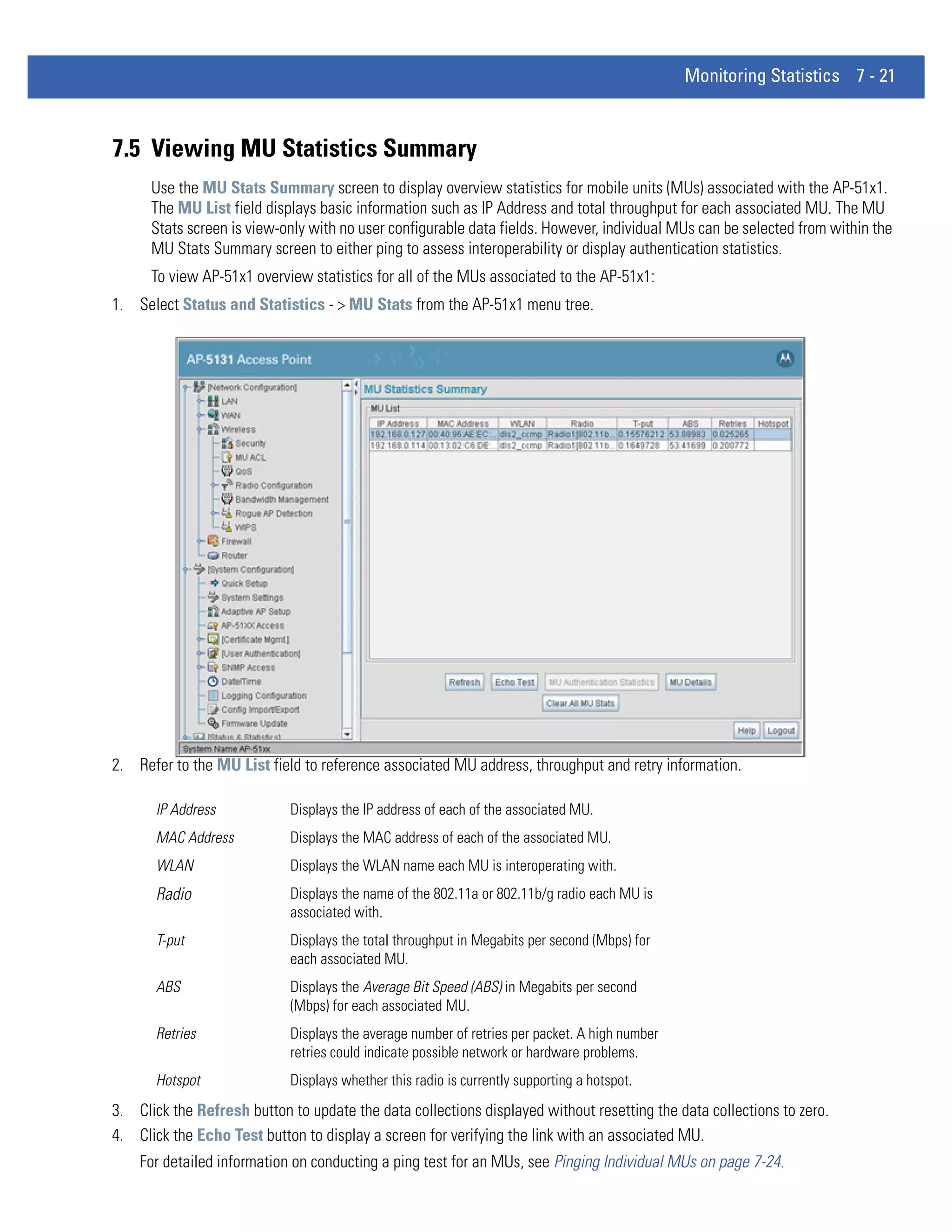
5. Click Apply to save the filename and Server IP information. The Apply button does not execute the import or export
operation, only saves the settings entered.
6. Click Undo Changes (if necessary) to undo any changes made. Undo Changes reverts the settings displayed on Config
Import/Export screen to the last saved configuration.
7. Click Logout to securely exit the AP-51x1 Motorola Solutions access point applet. A prompt displays confirming the logout
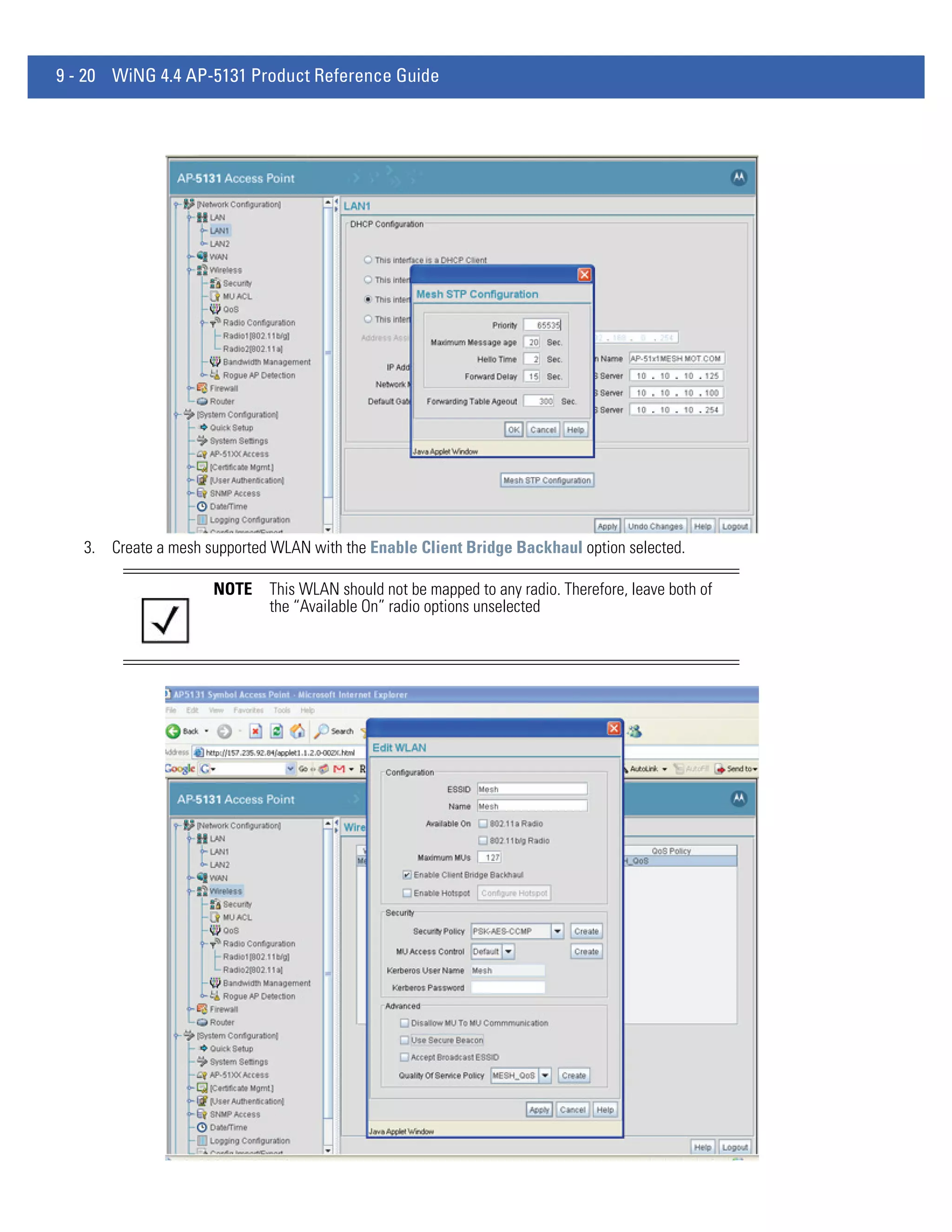
before the applet is closed.](https://image.slidesharecdn.com/motorolasolutionswing4-4ap51xxaccesspointproductreferenceguidepartno-72e-157066-01rev-a-120807142110-phpapp02/75/Motorola-solutions-wing-4-4-ap51xx-access-point-product-reference-guide-part-no-72-e-157066-01-rev-a-114-2048.jpg)


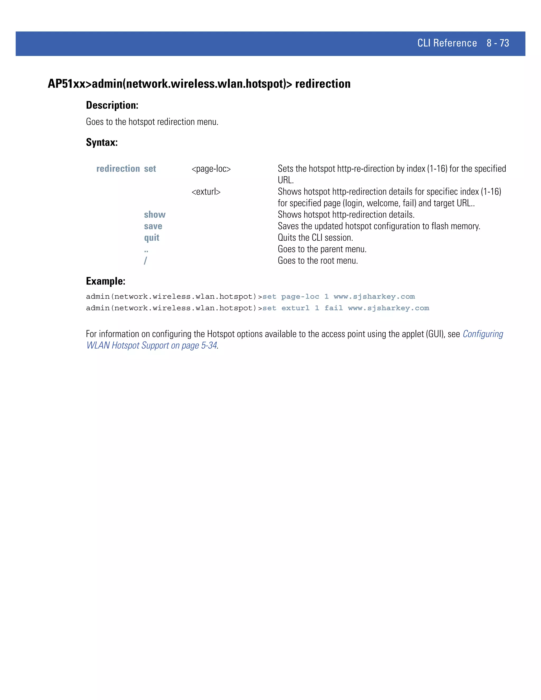


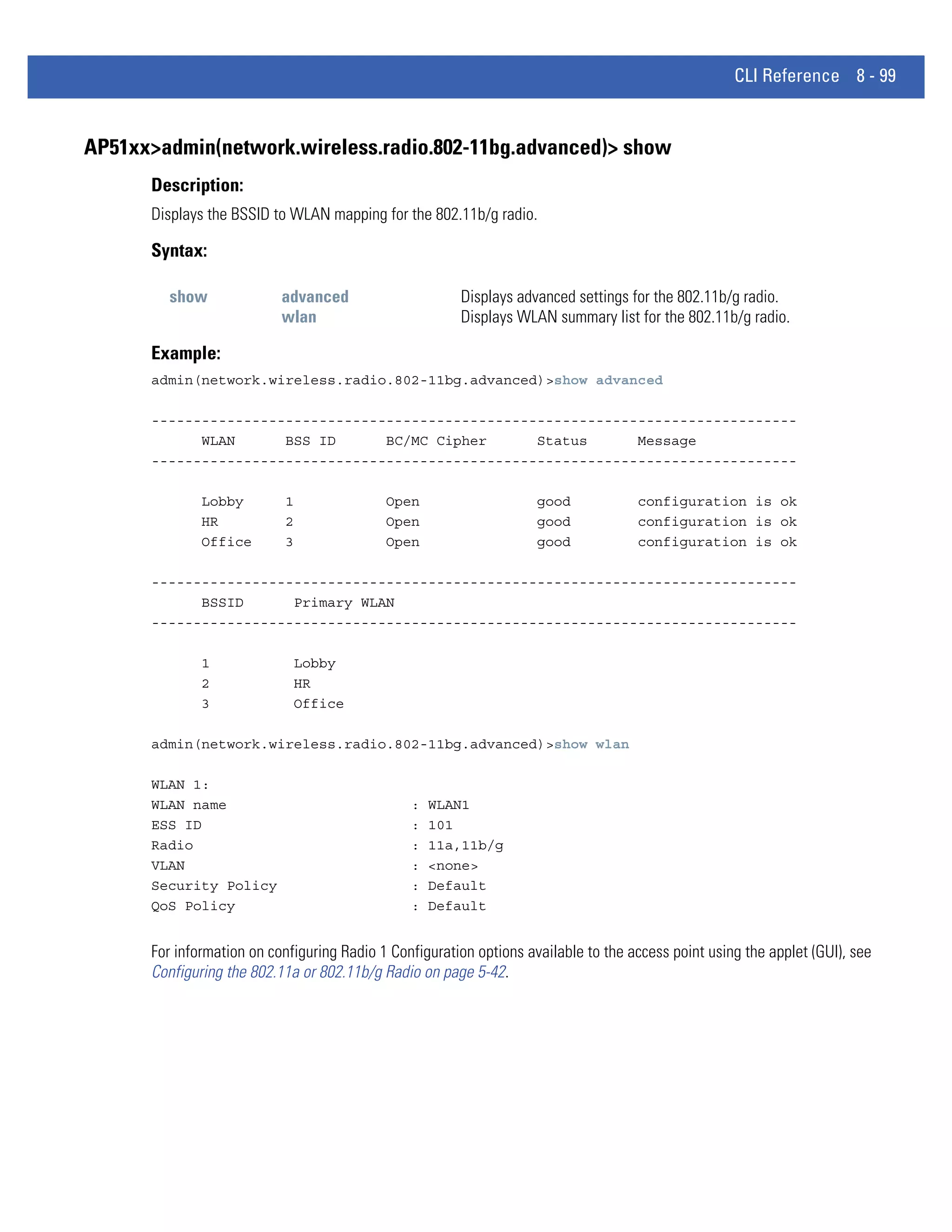


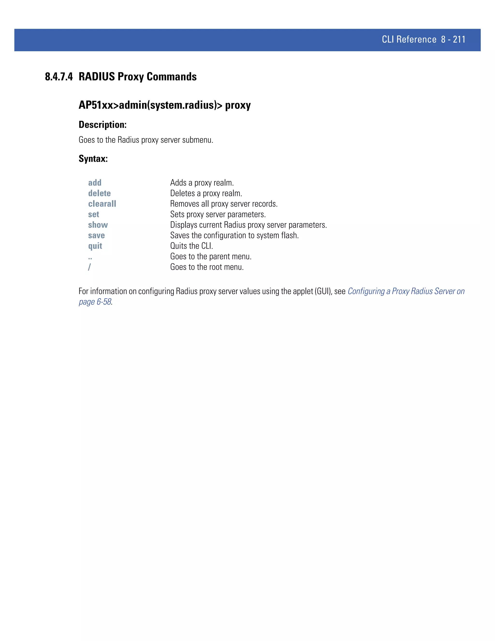
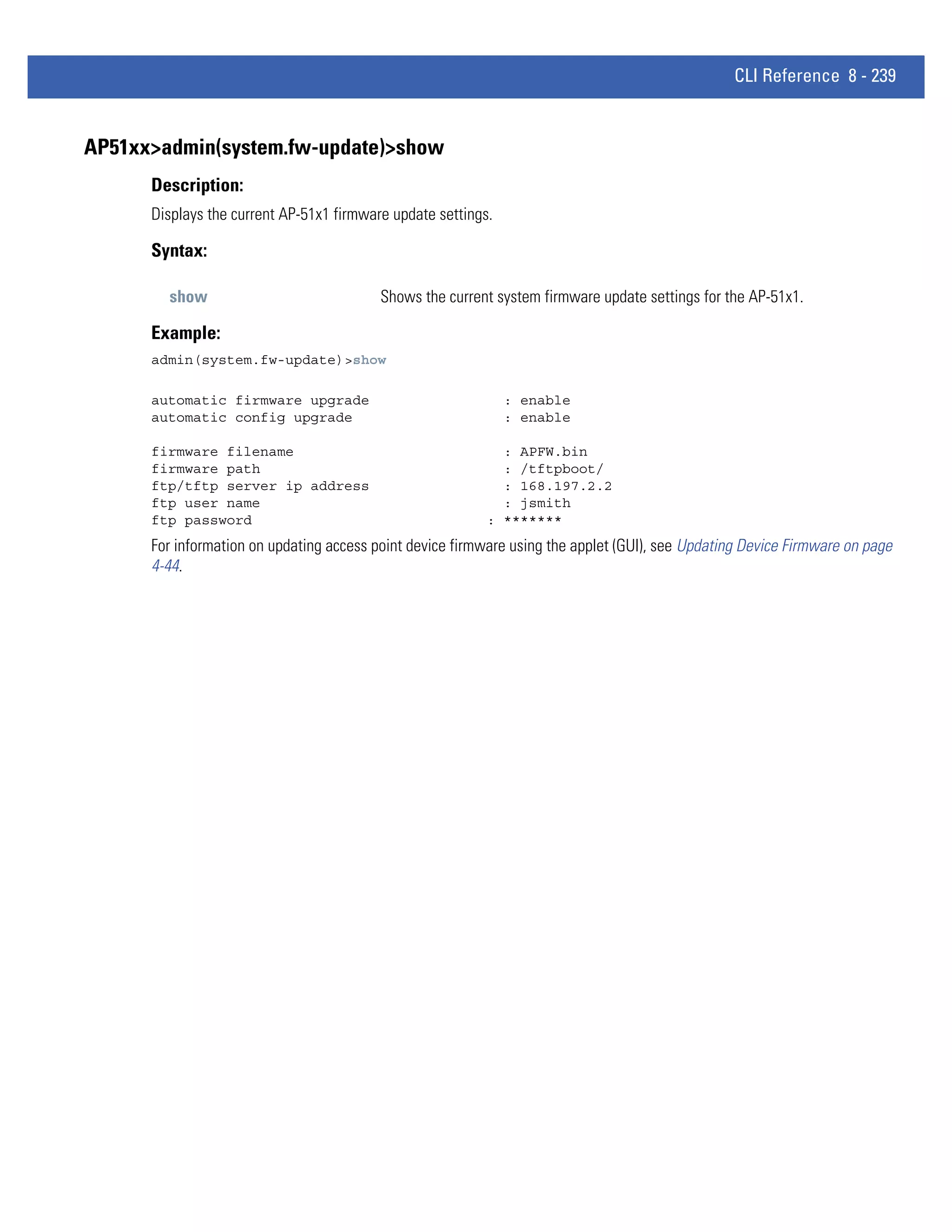
![CLI Reference 8 - 159
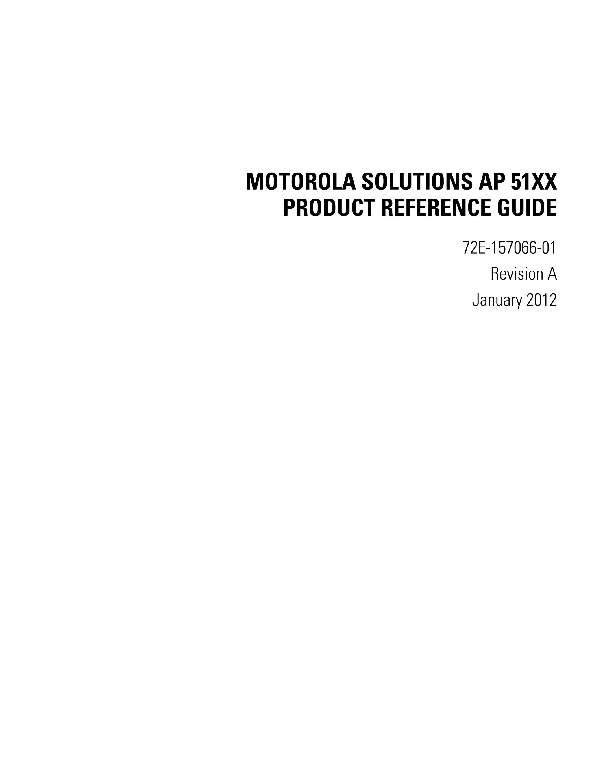
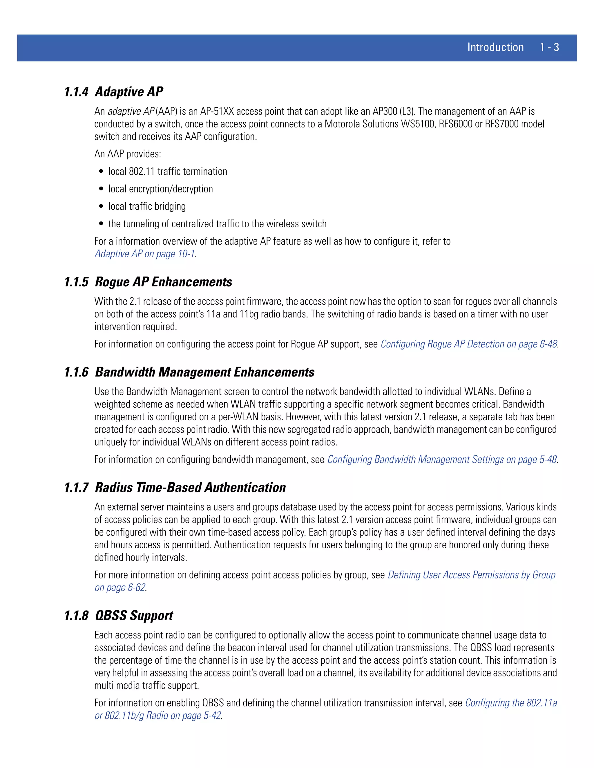
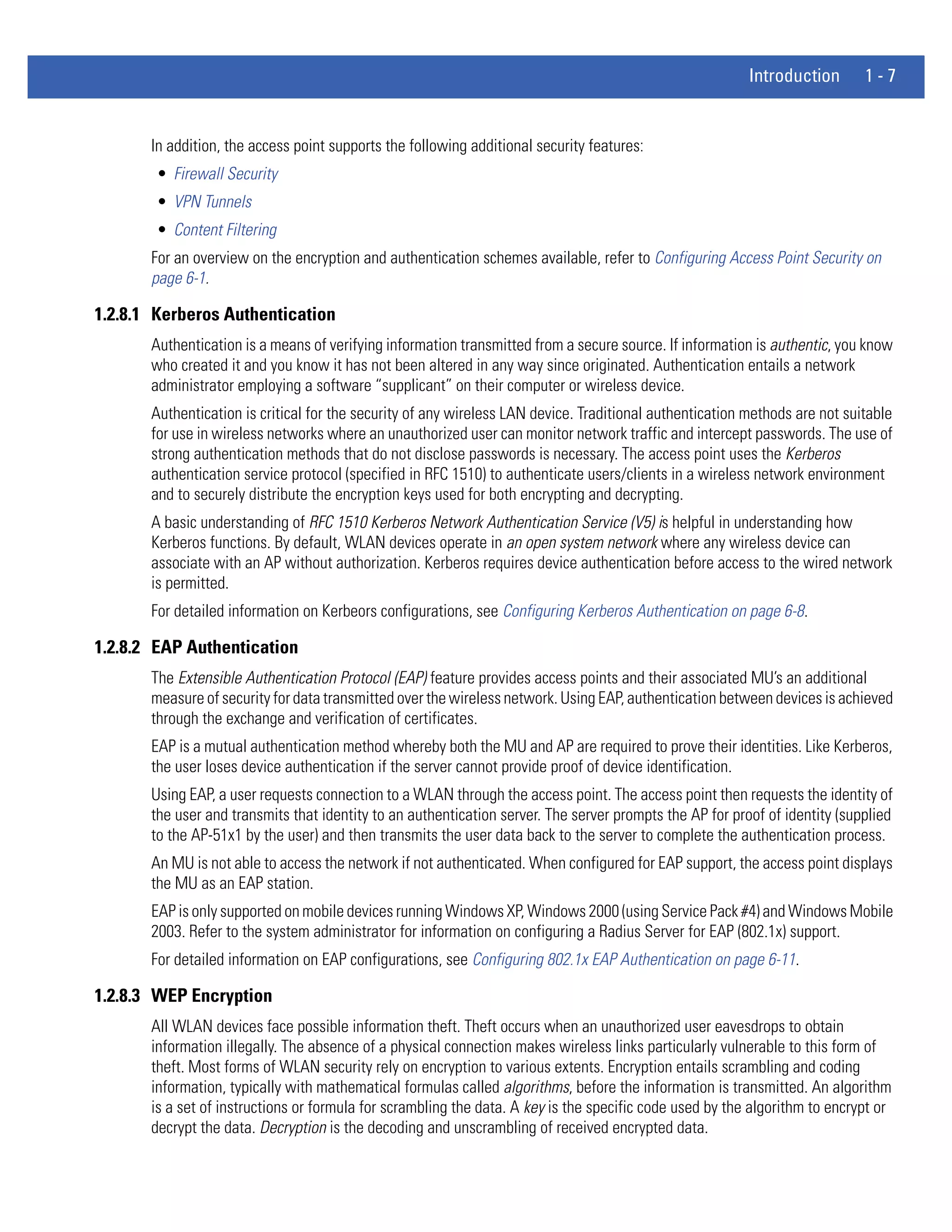
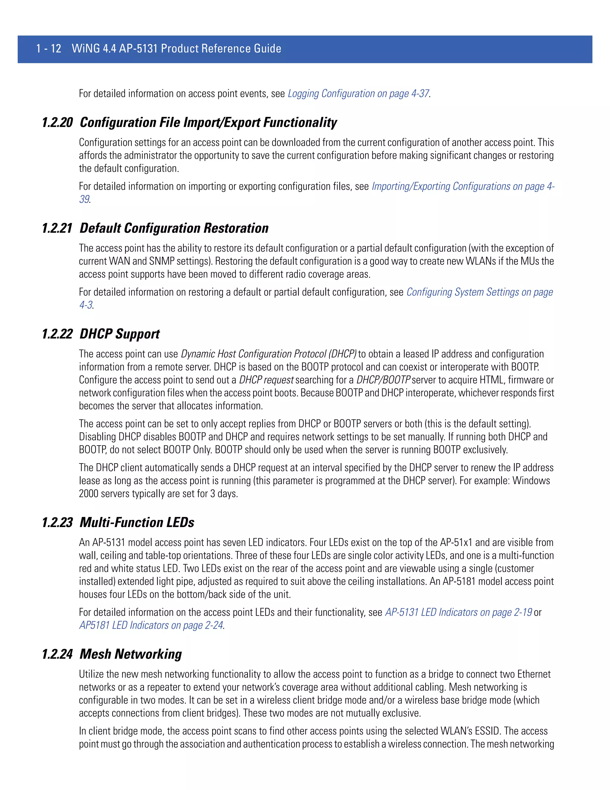
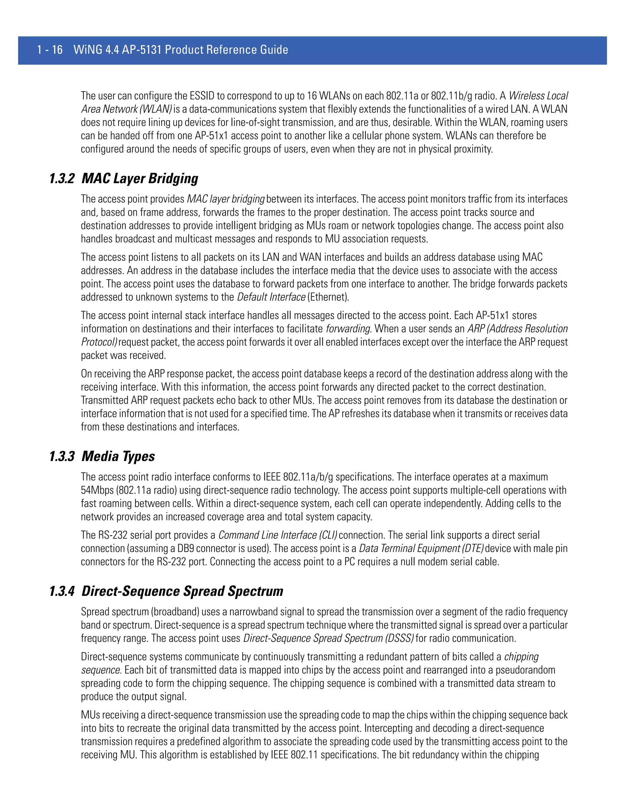
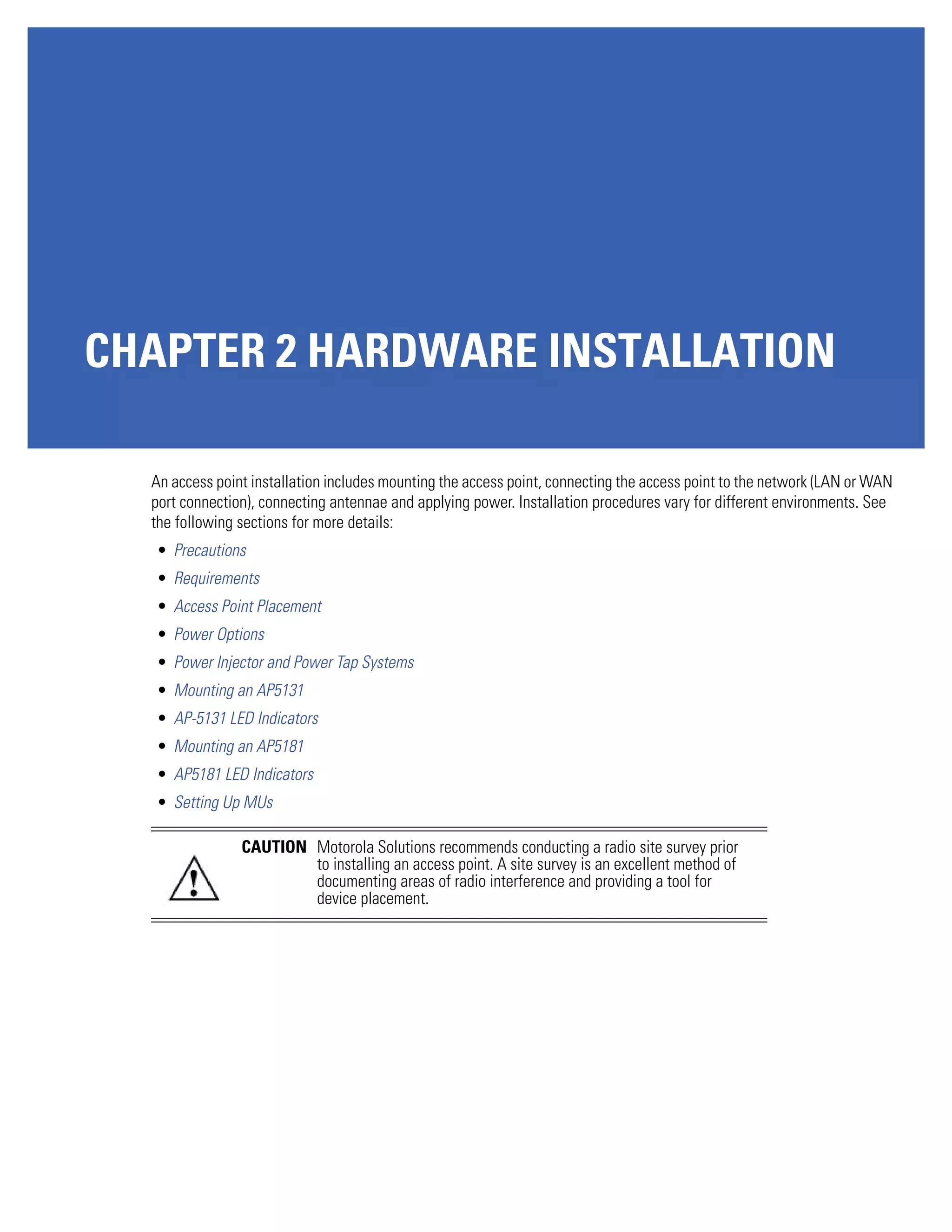
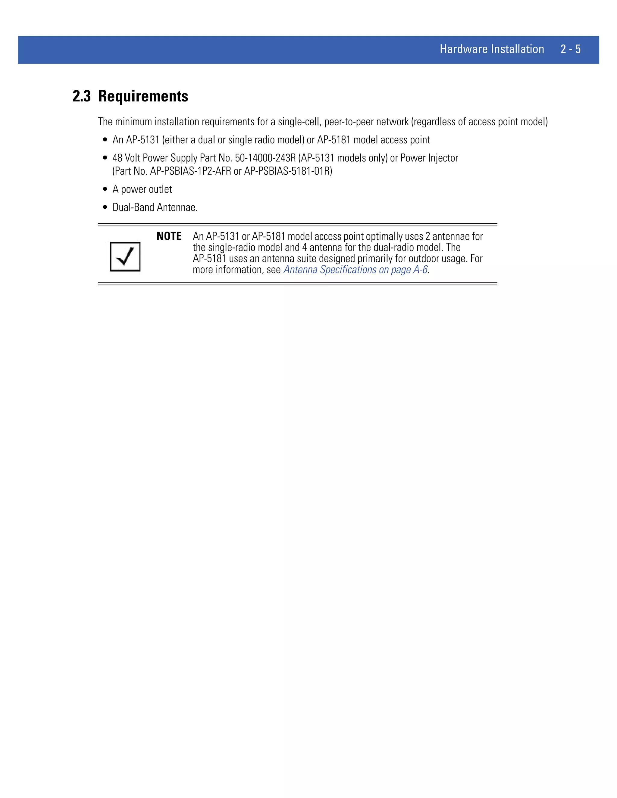
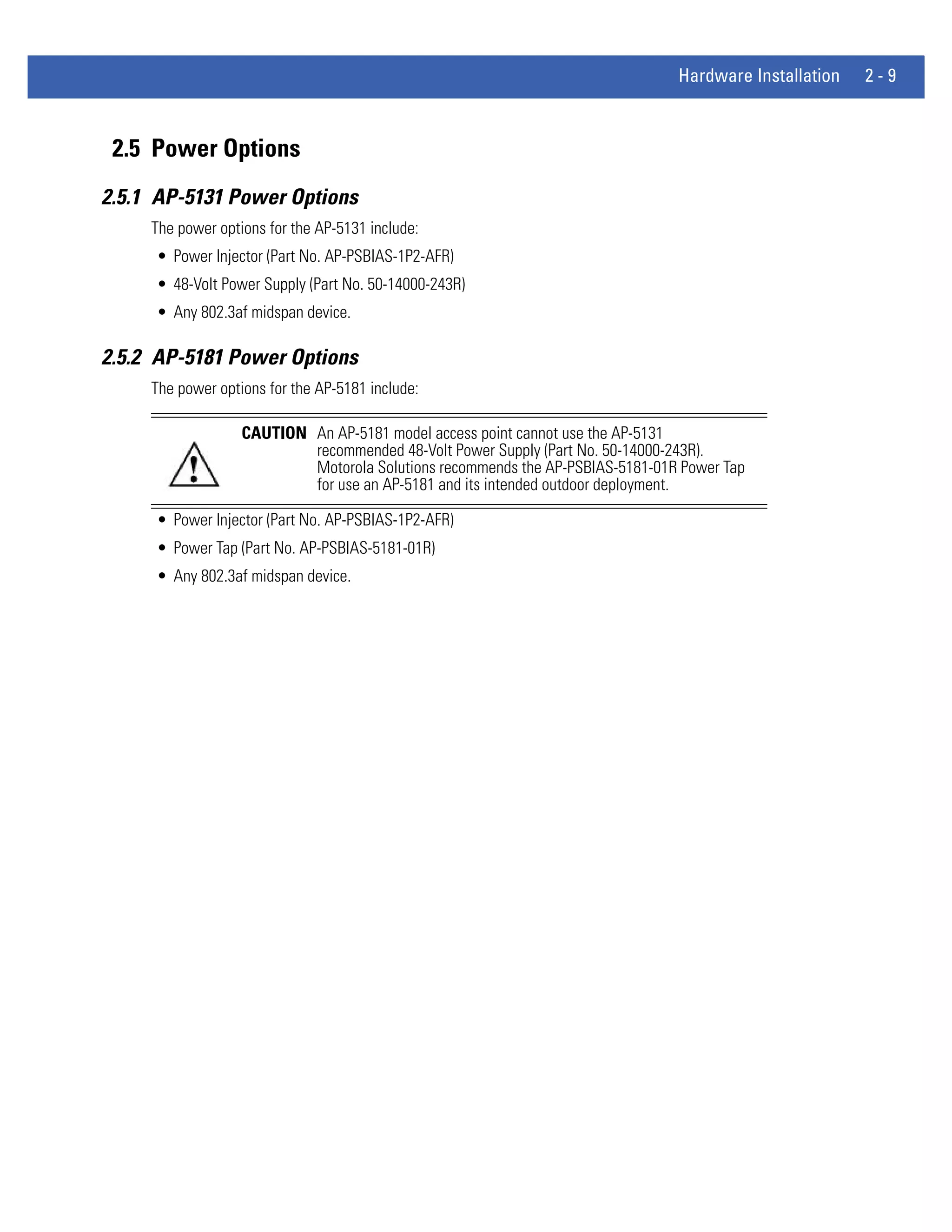
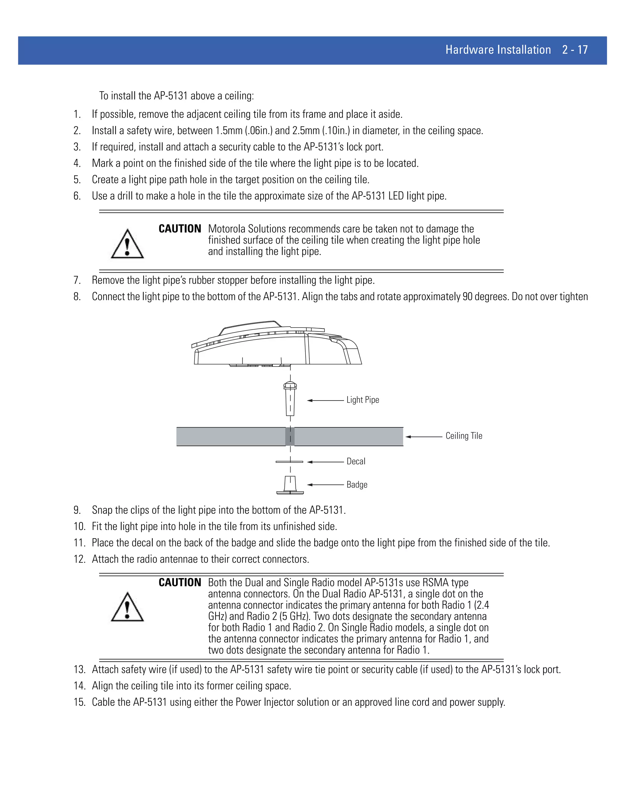
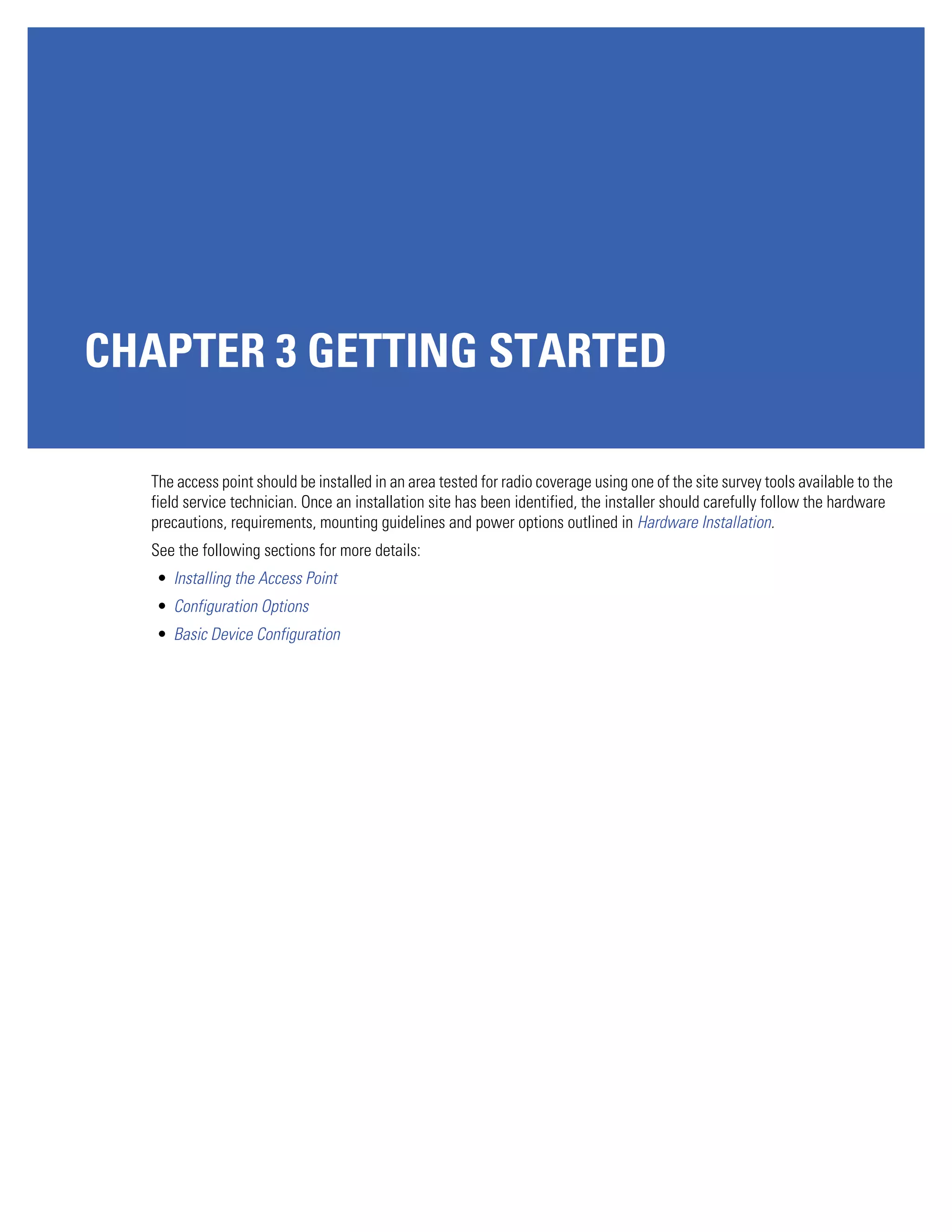
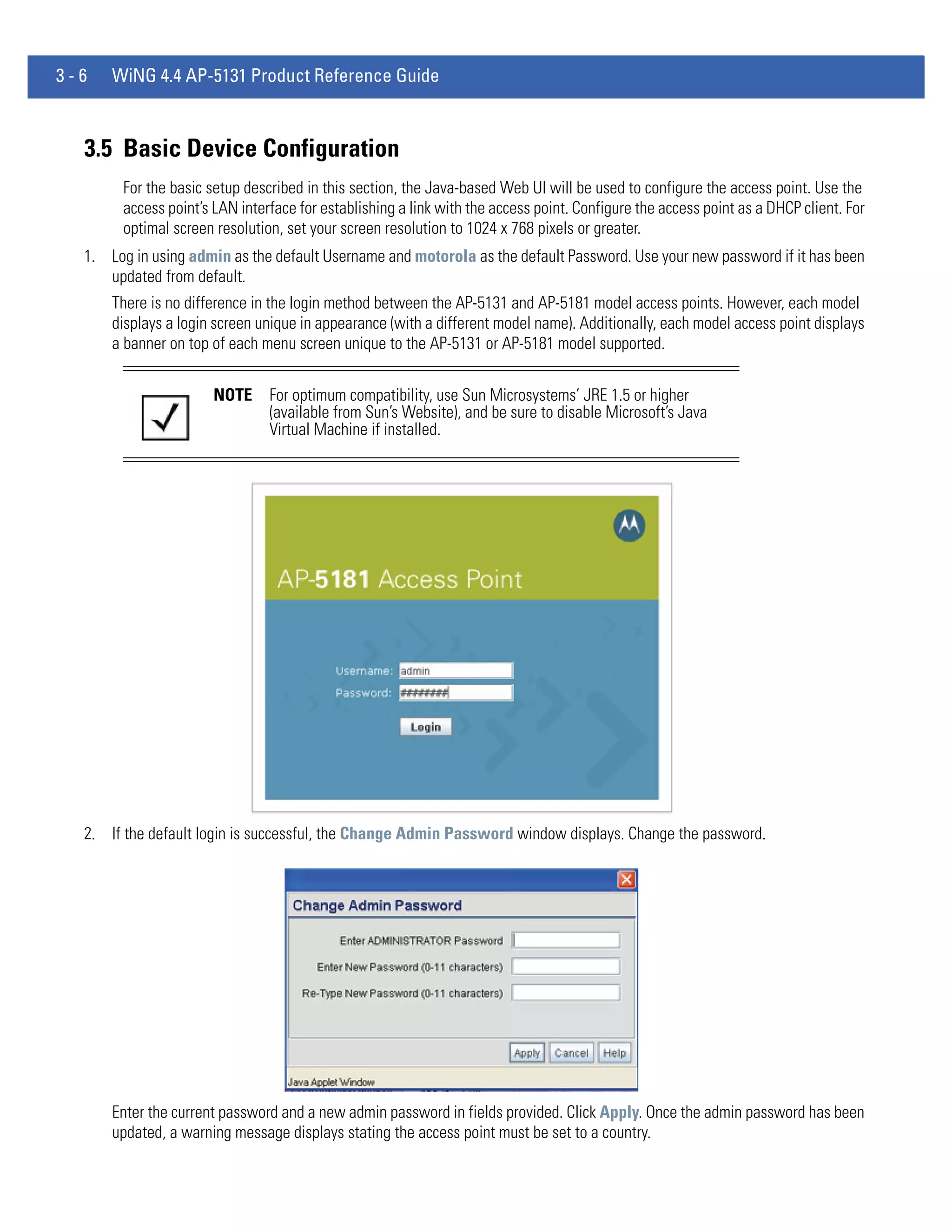
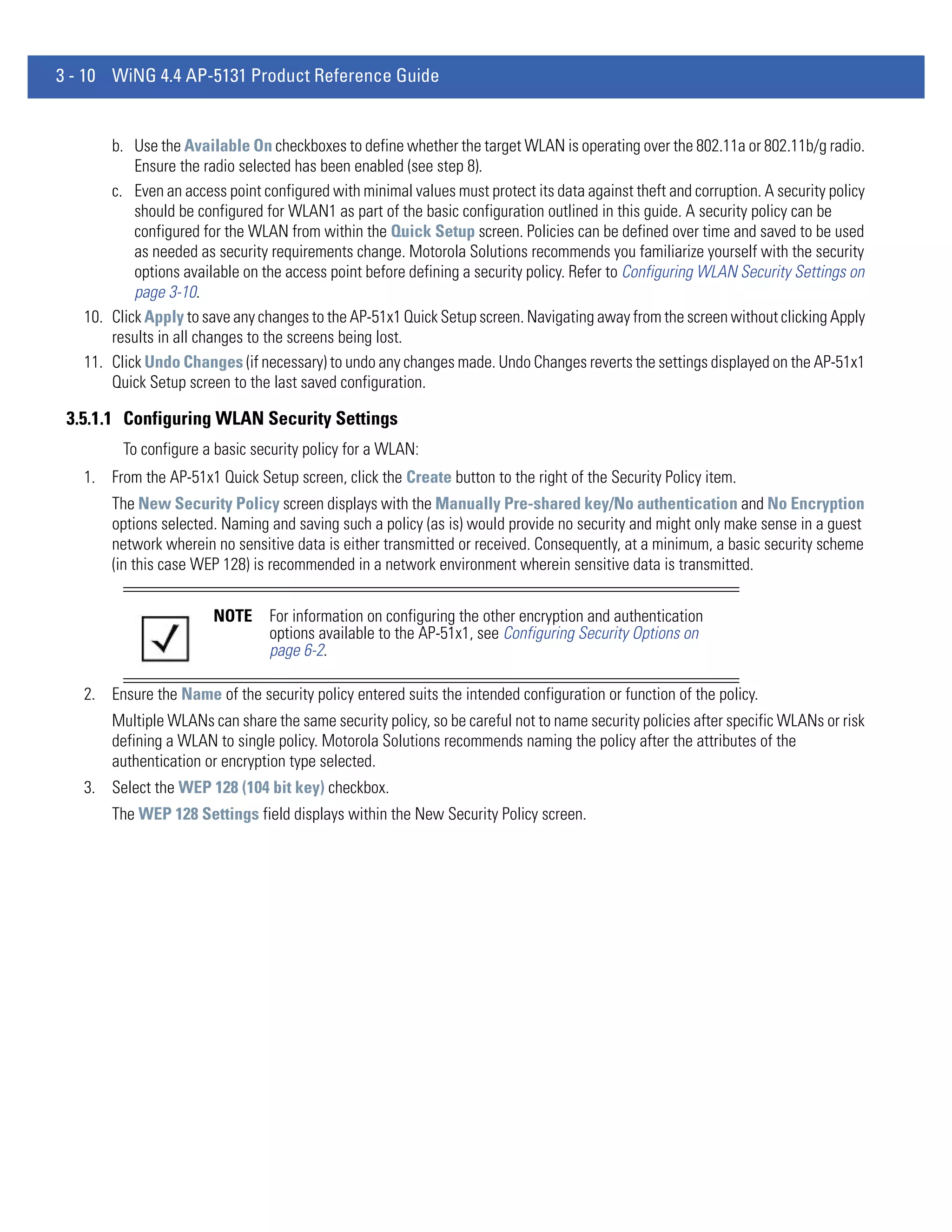
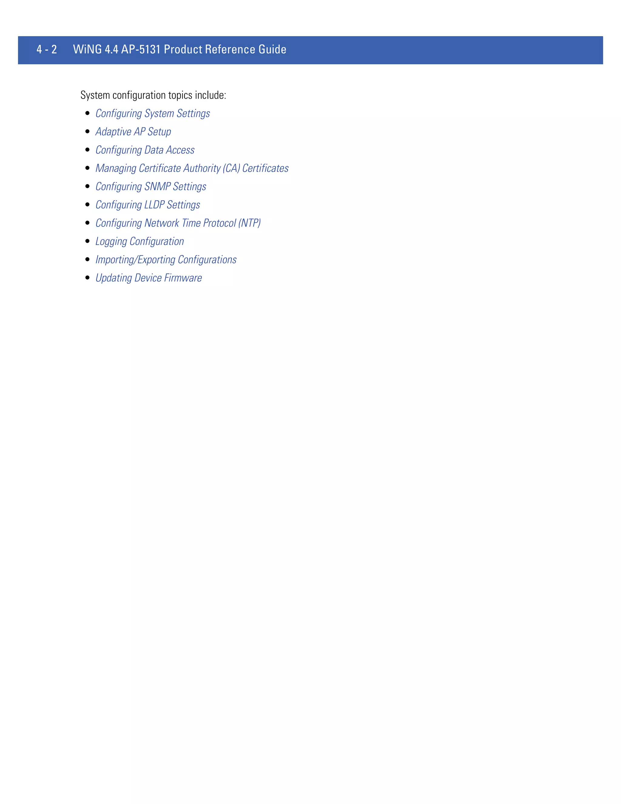
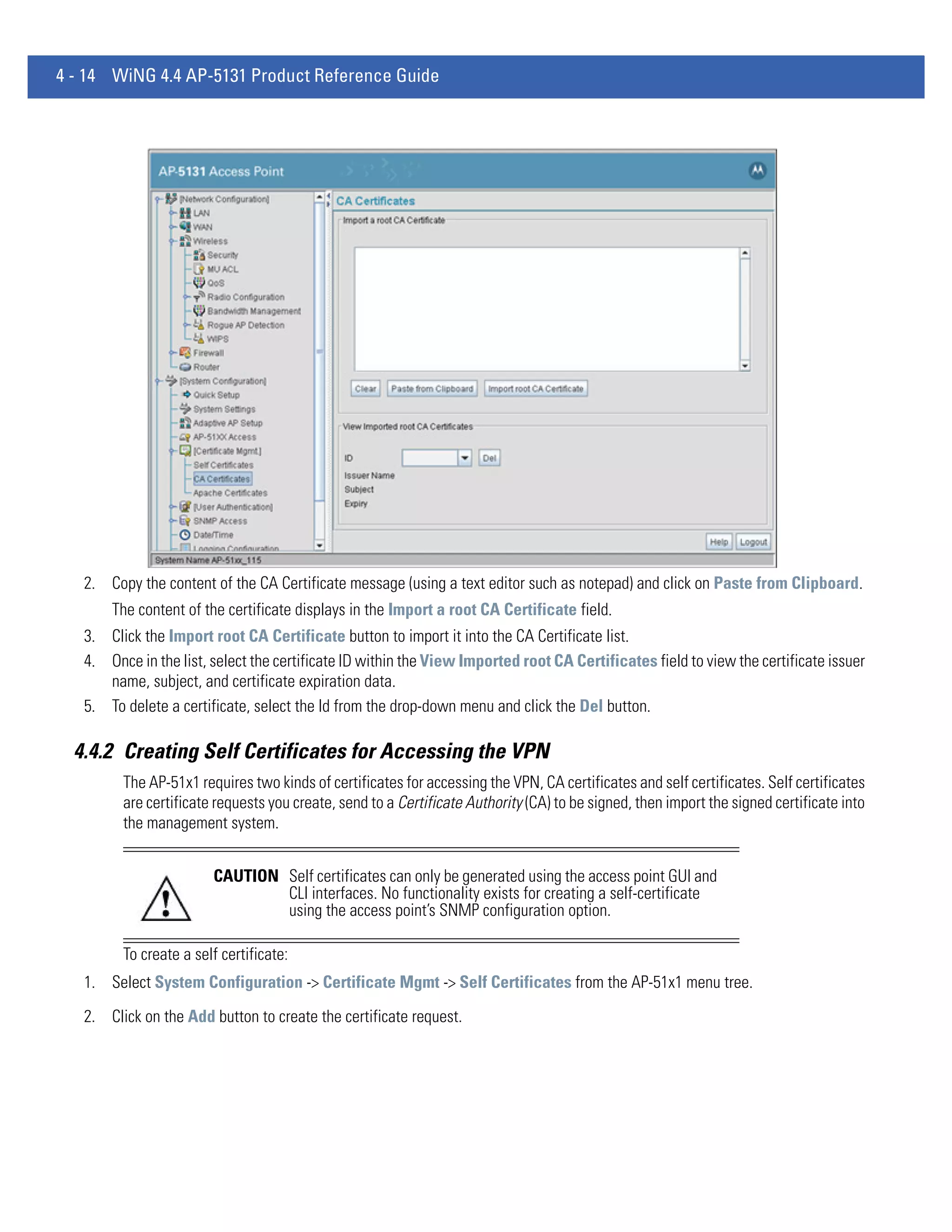
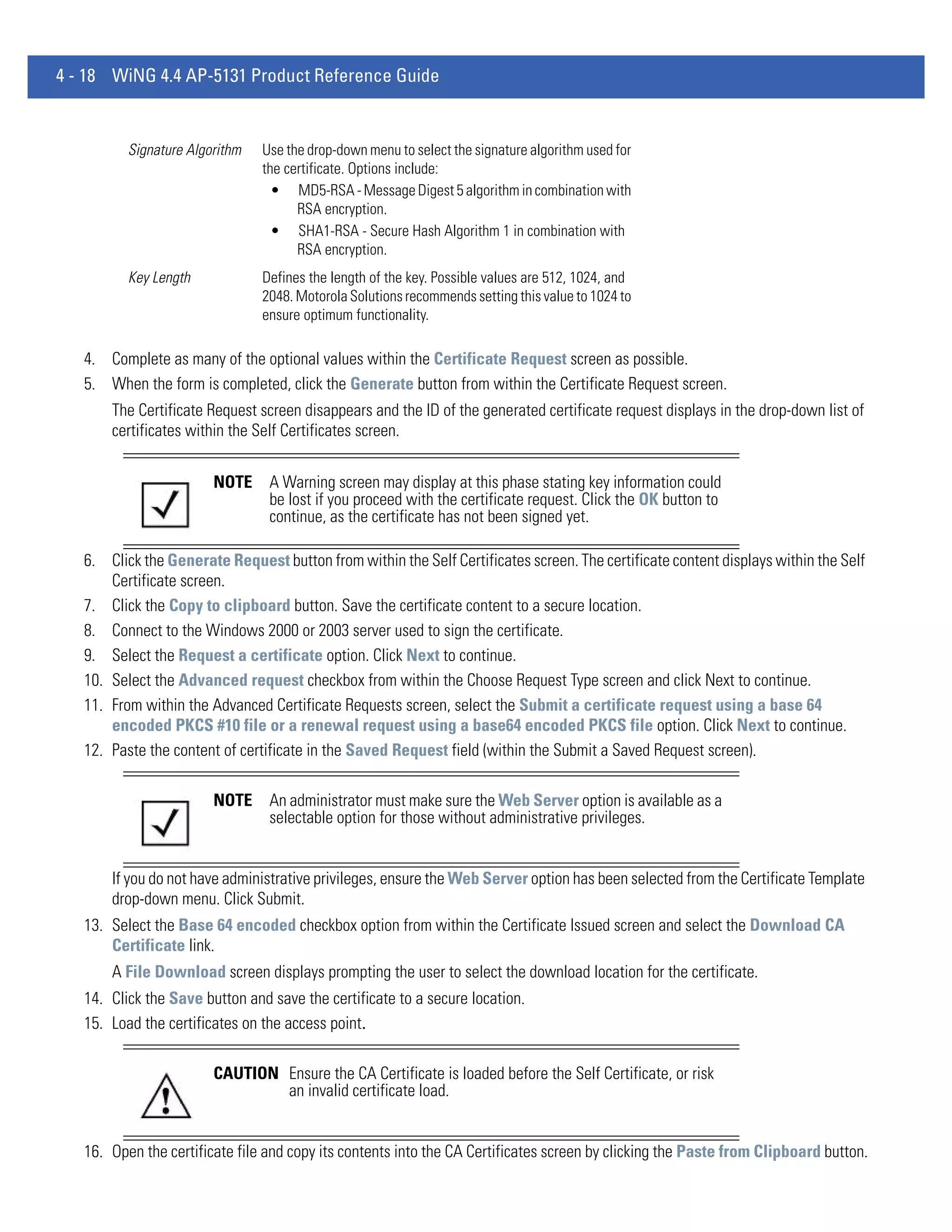
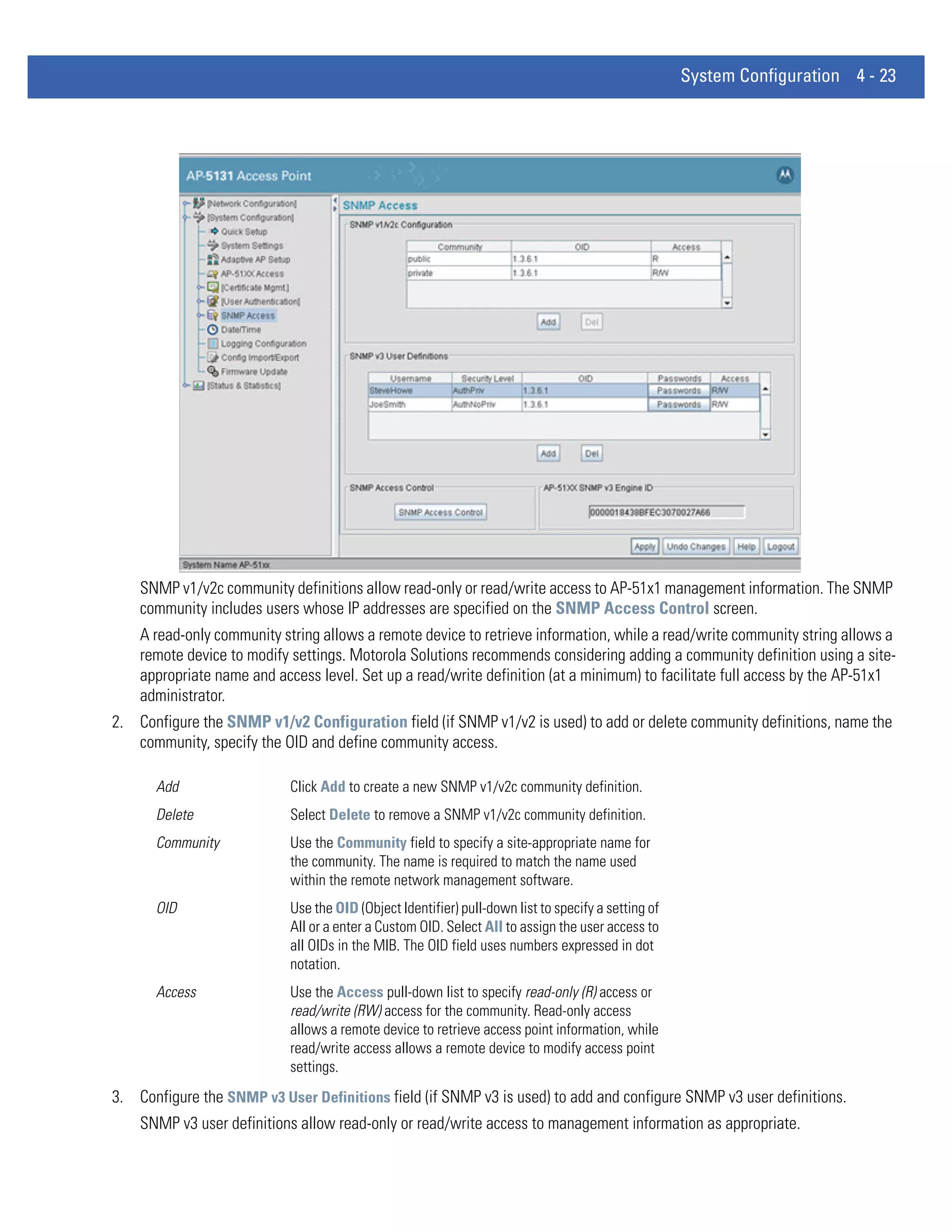
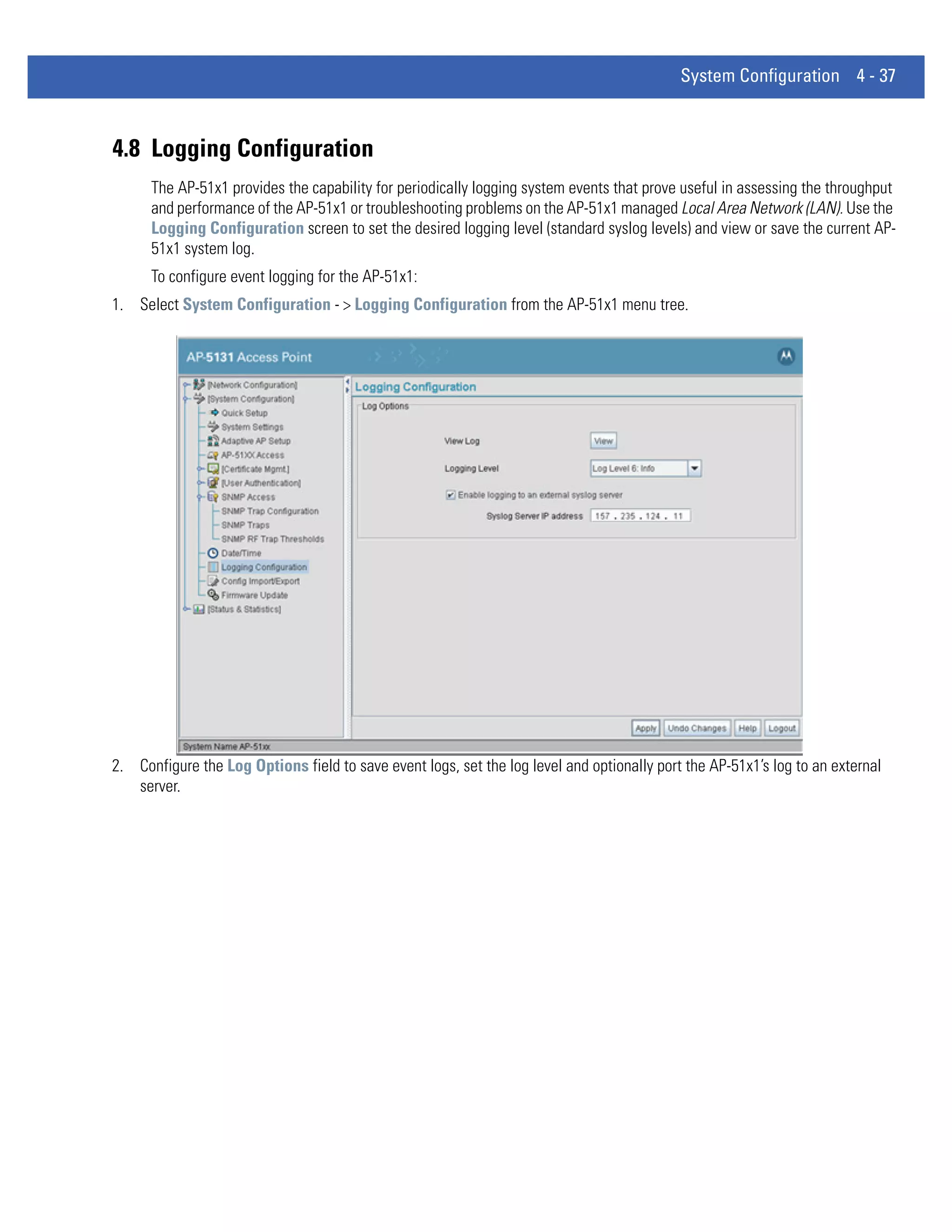
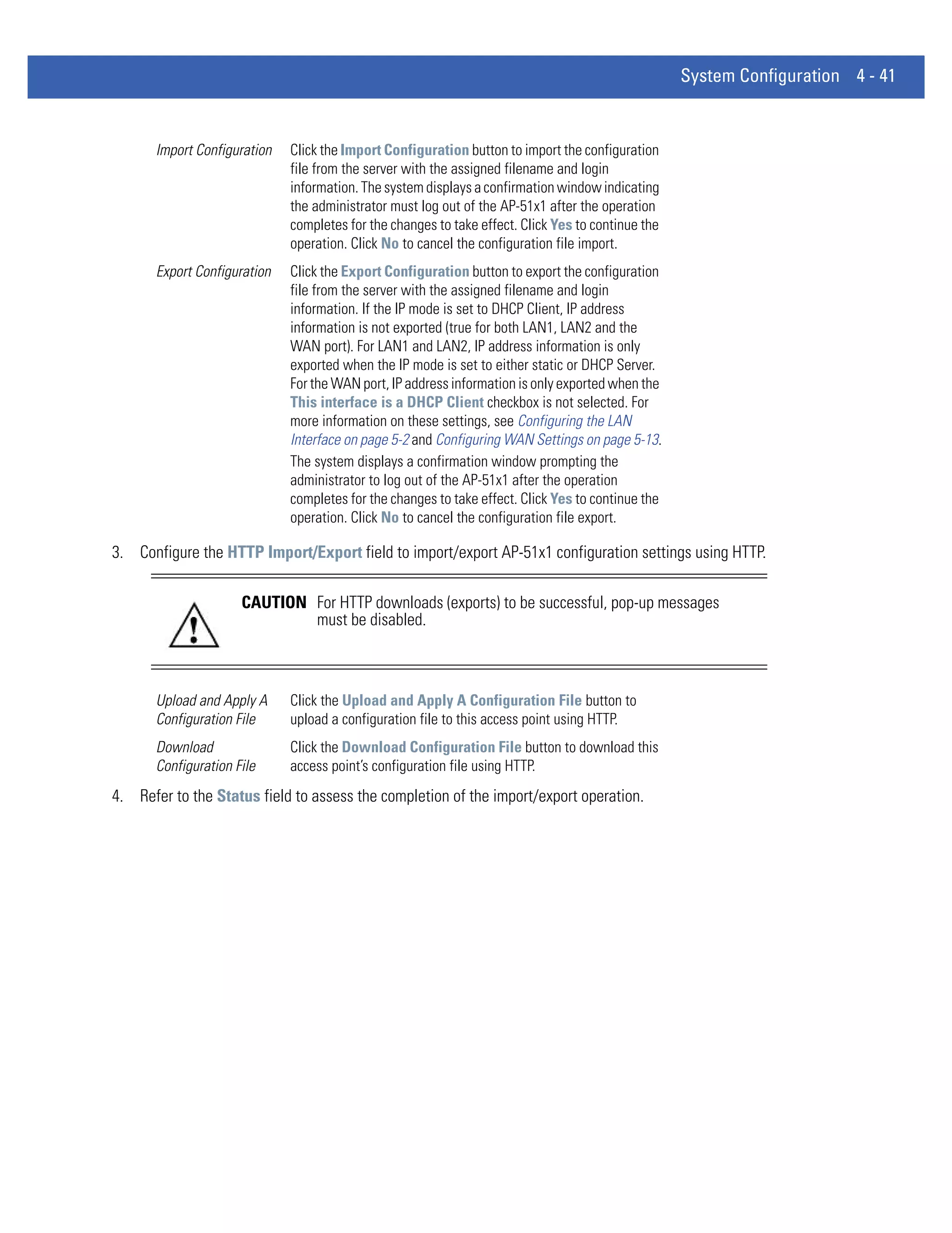
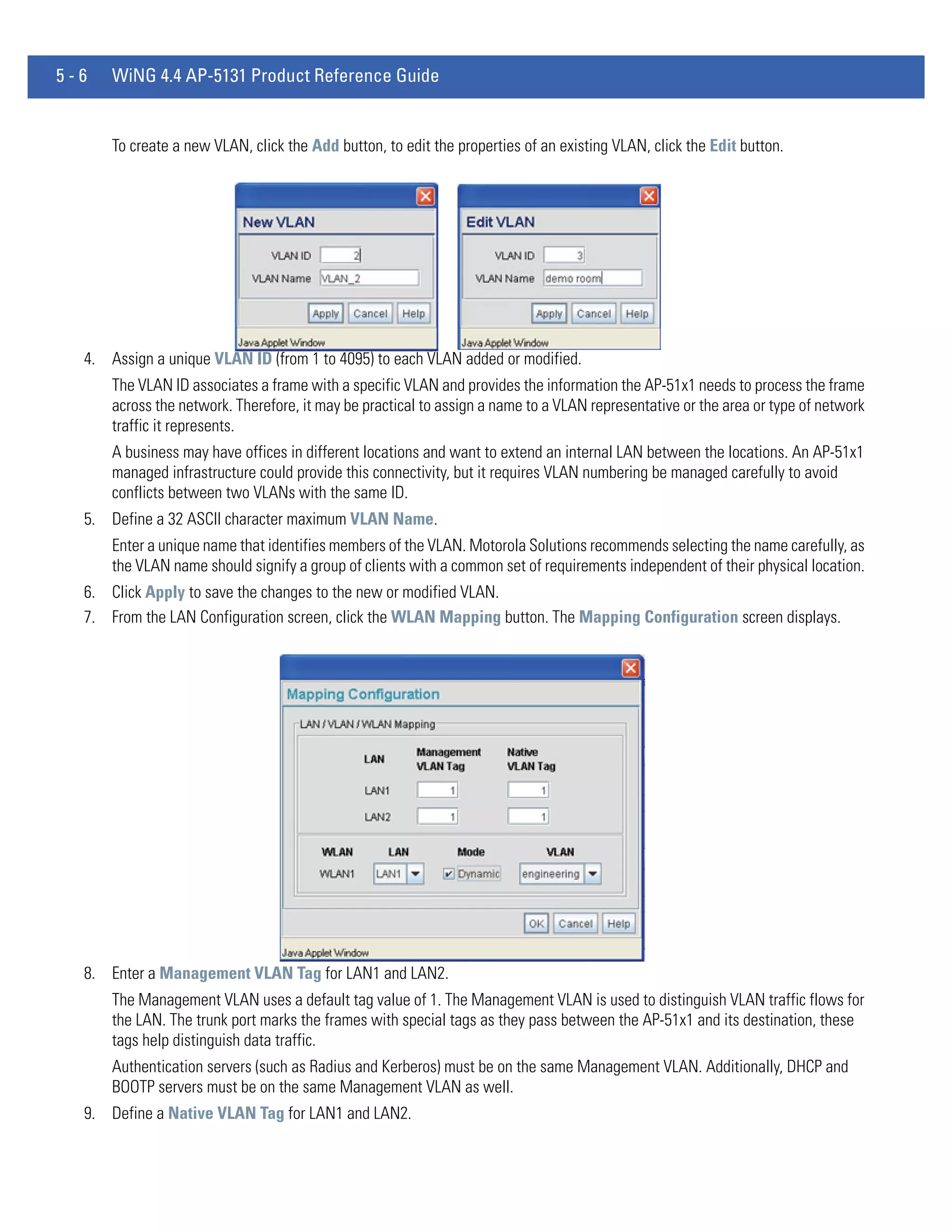
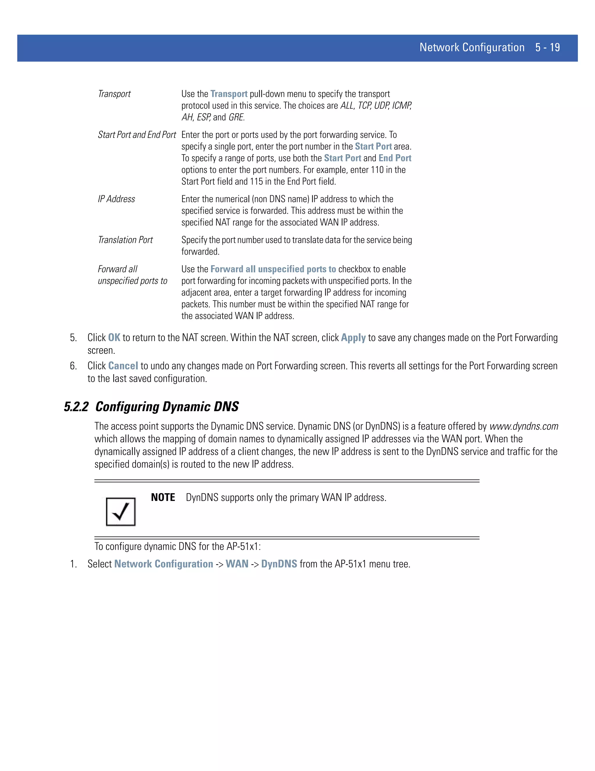
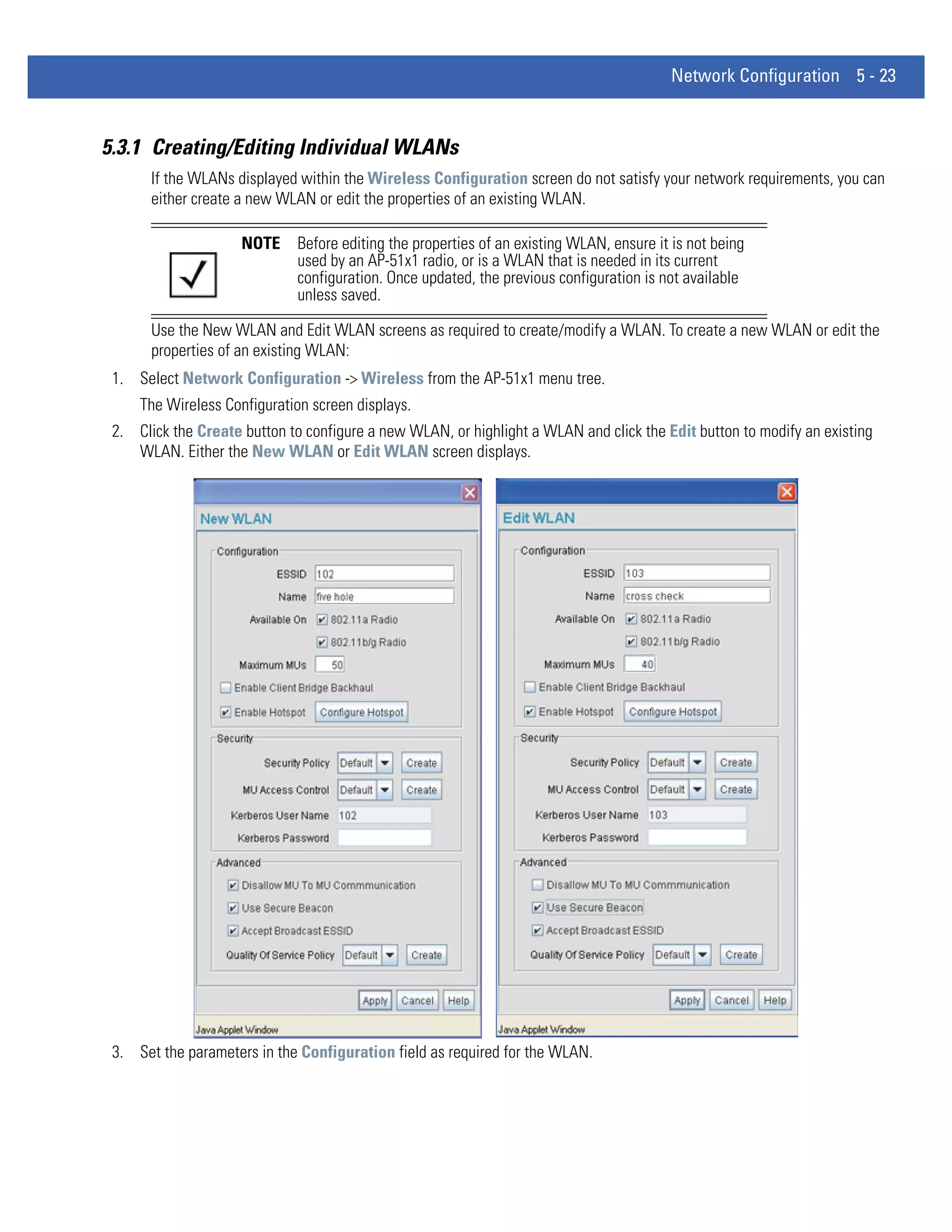
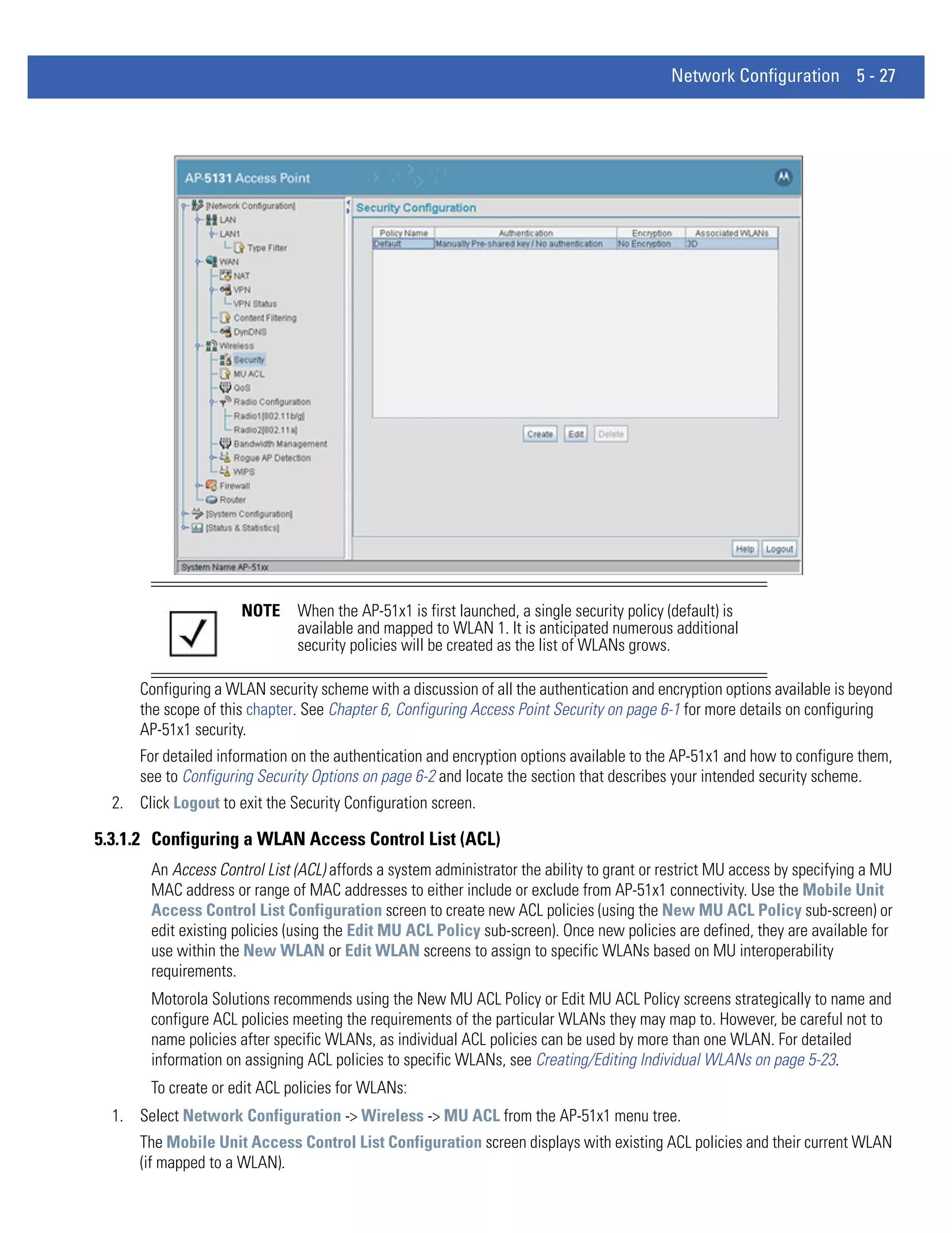
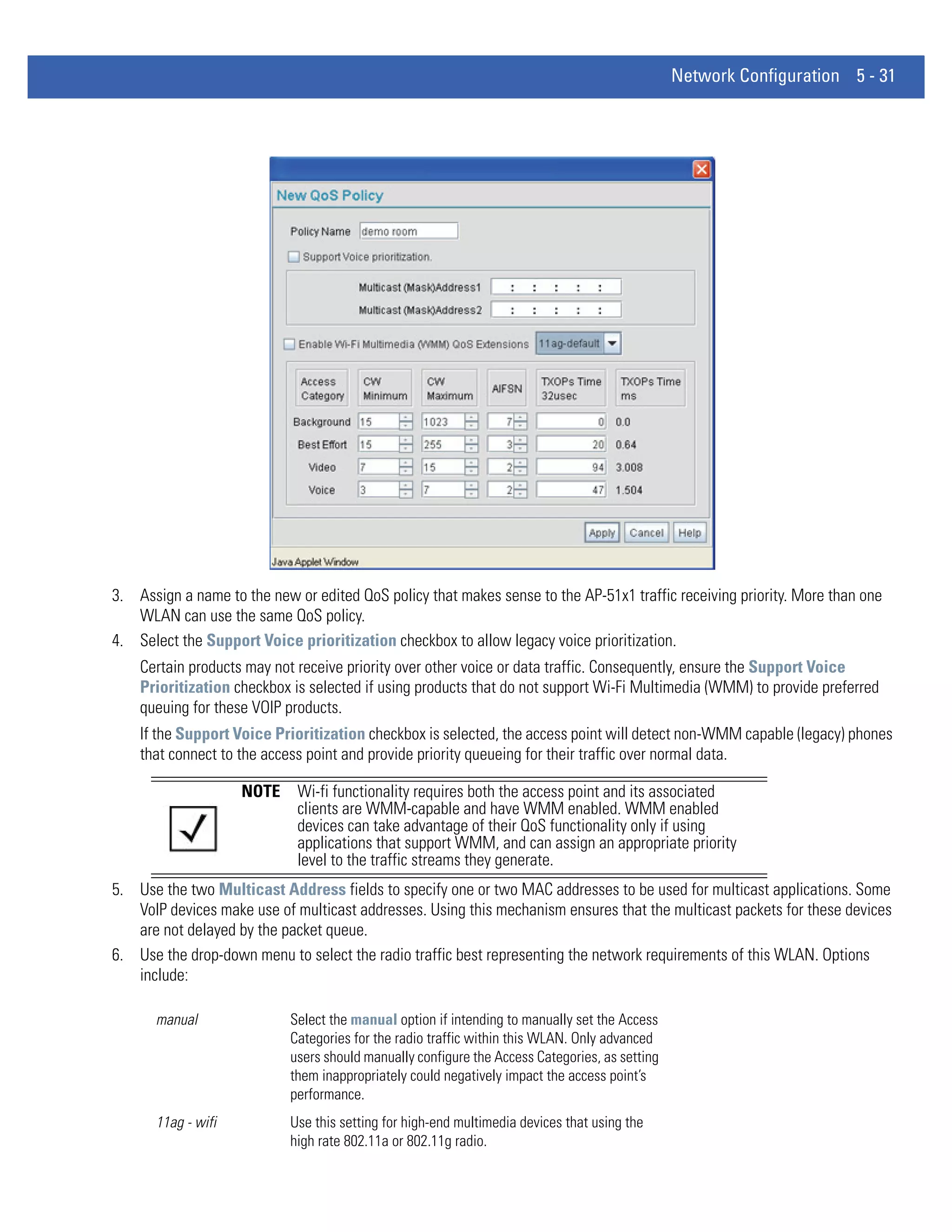
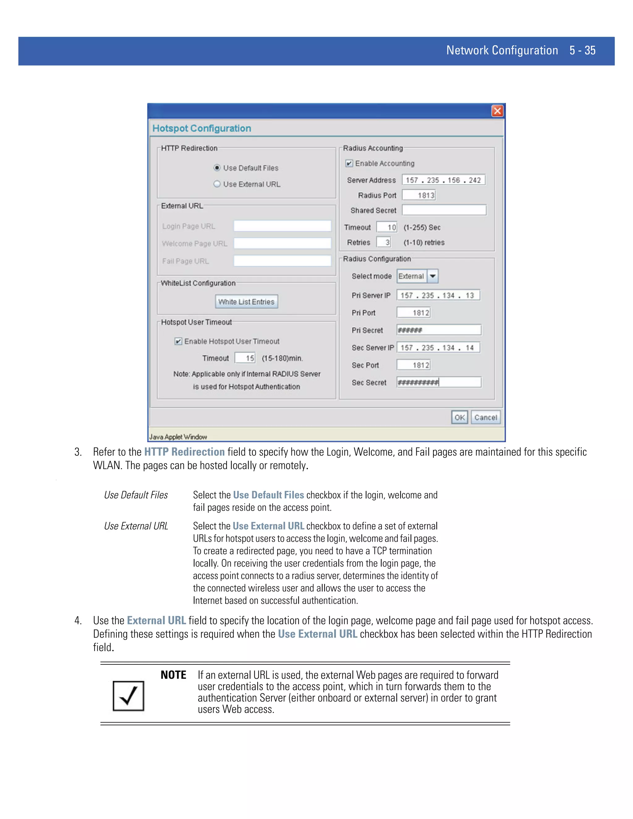
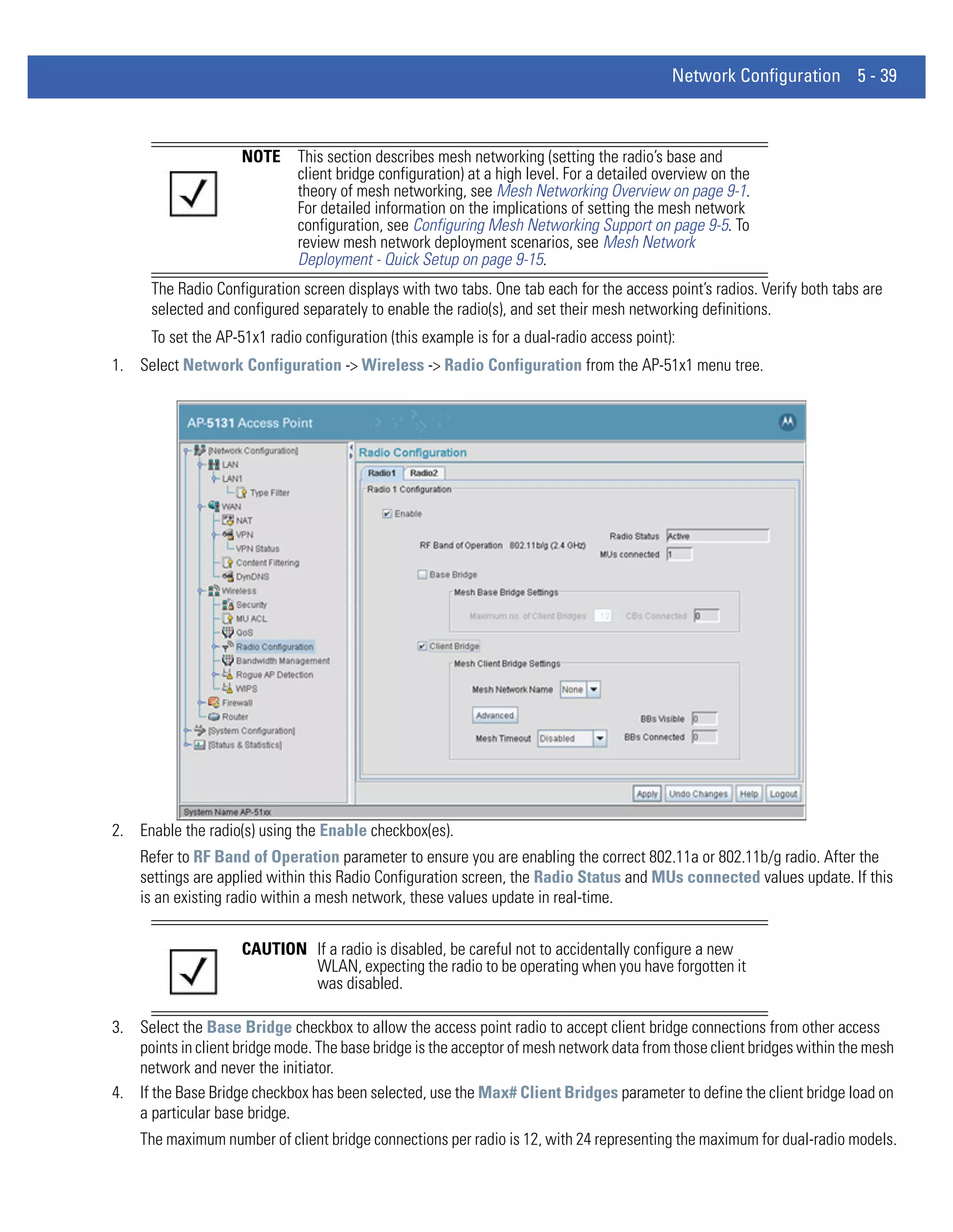
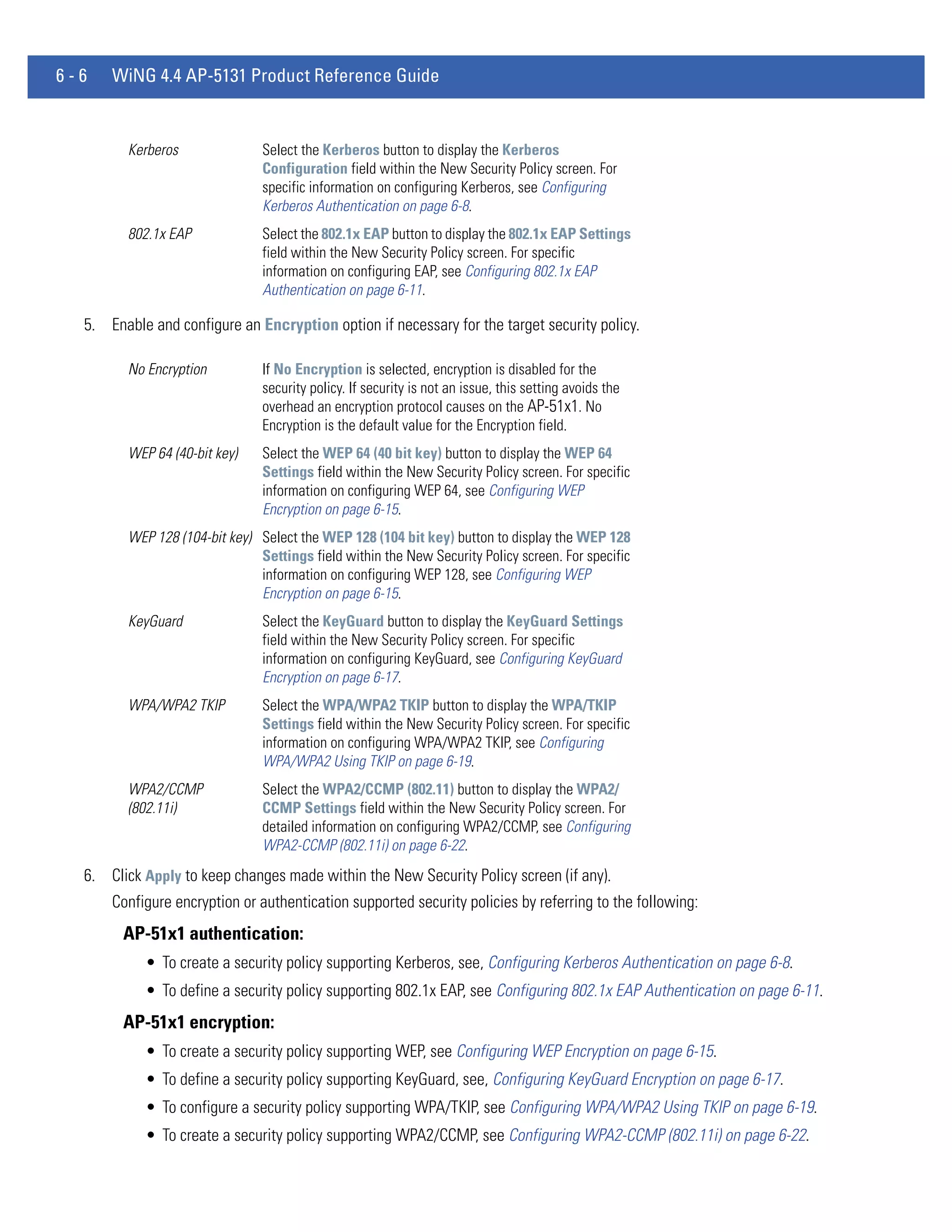
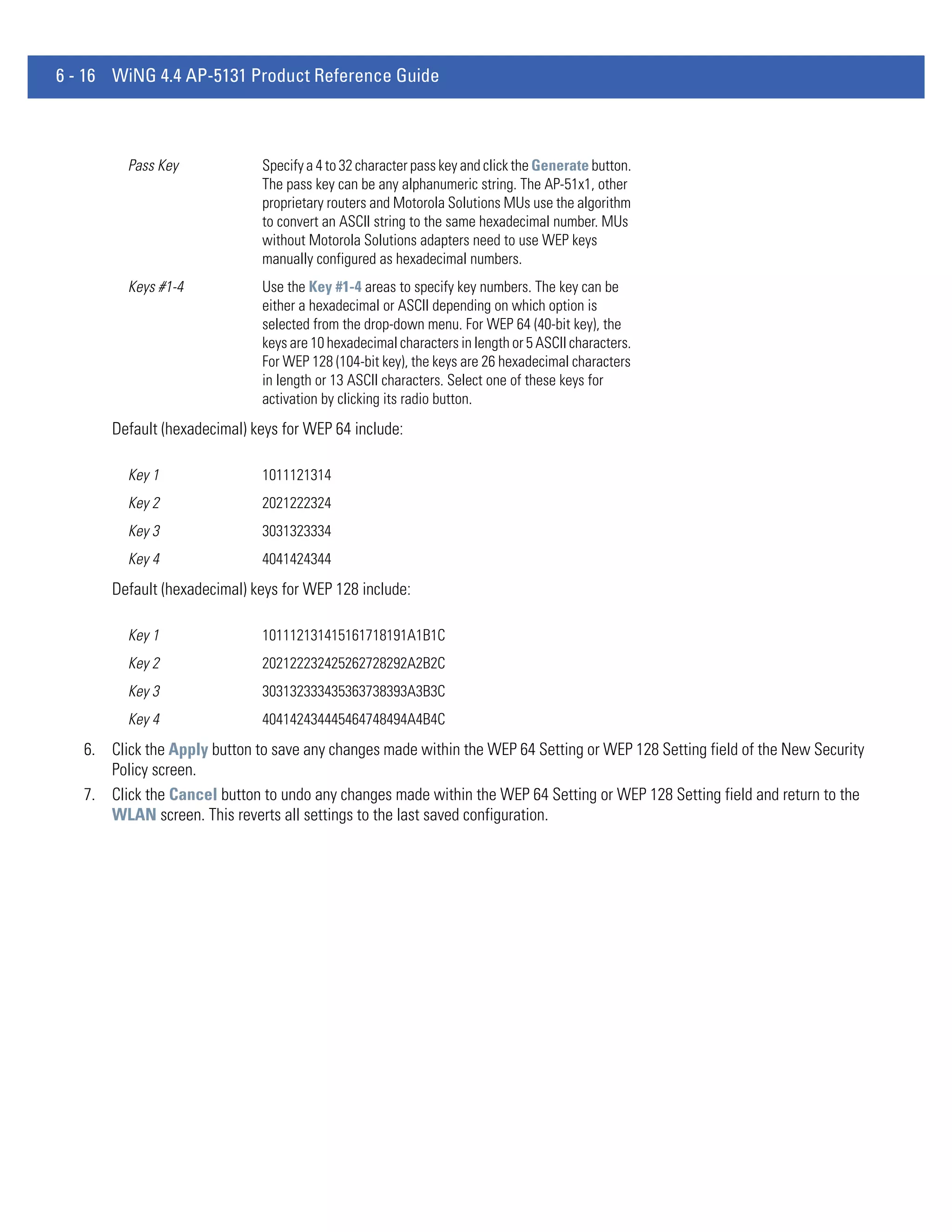
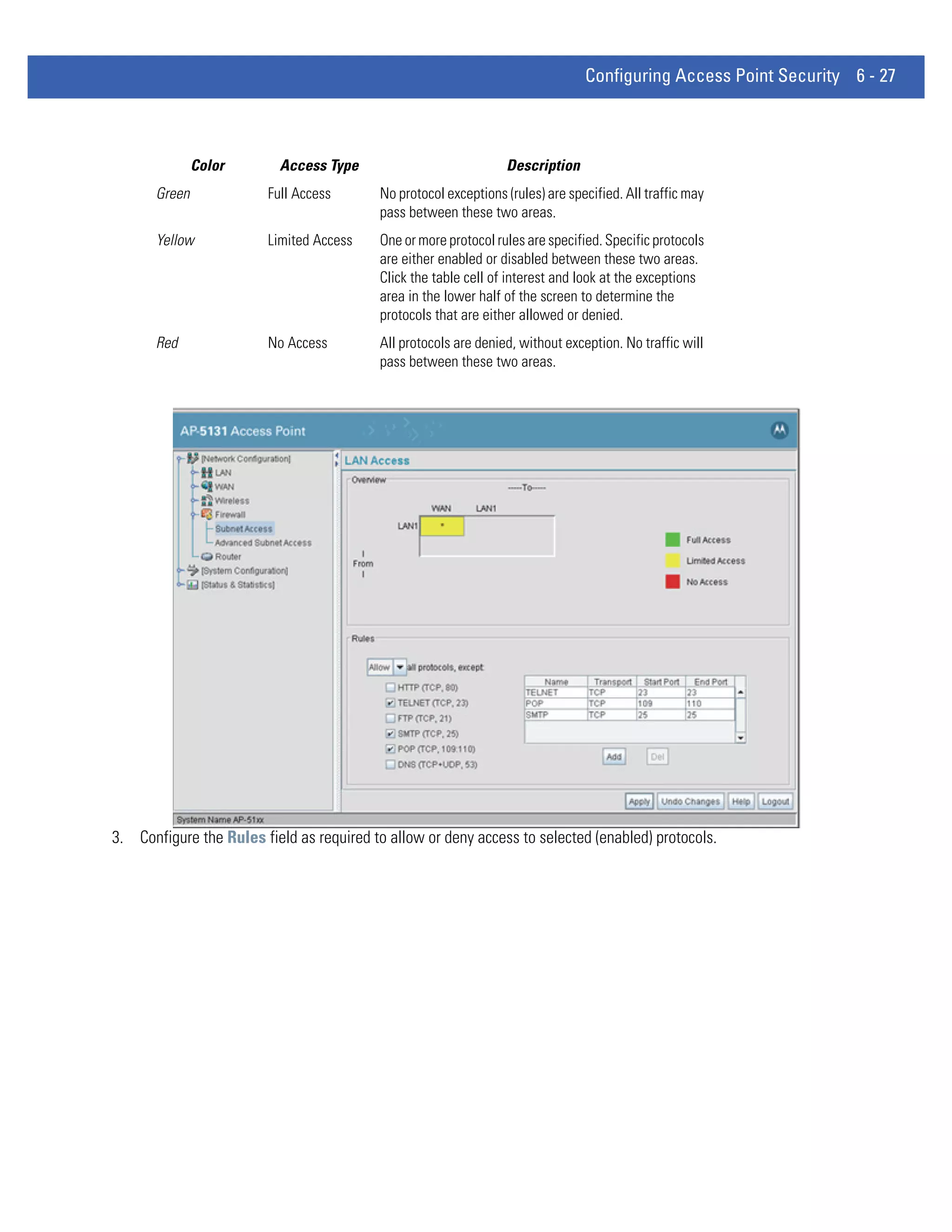
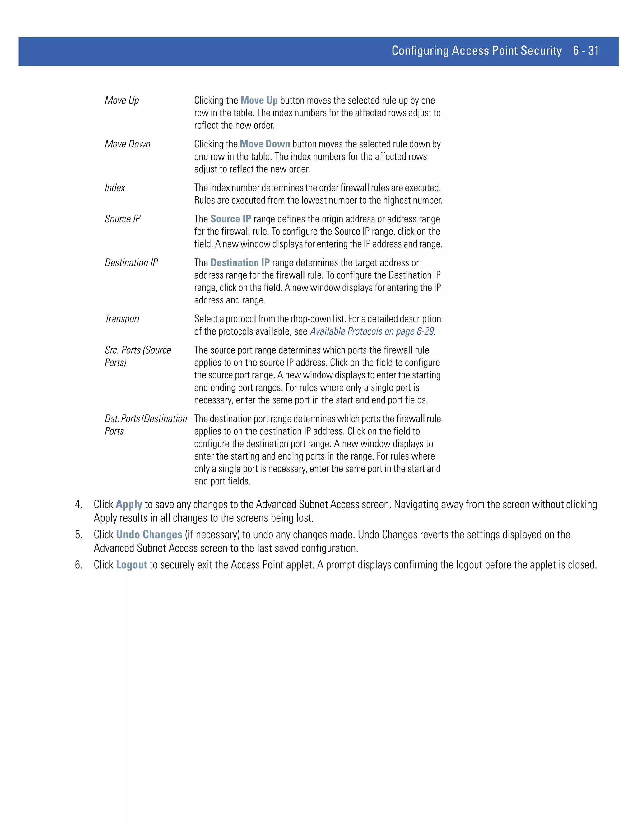
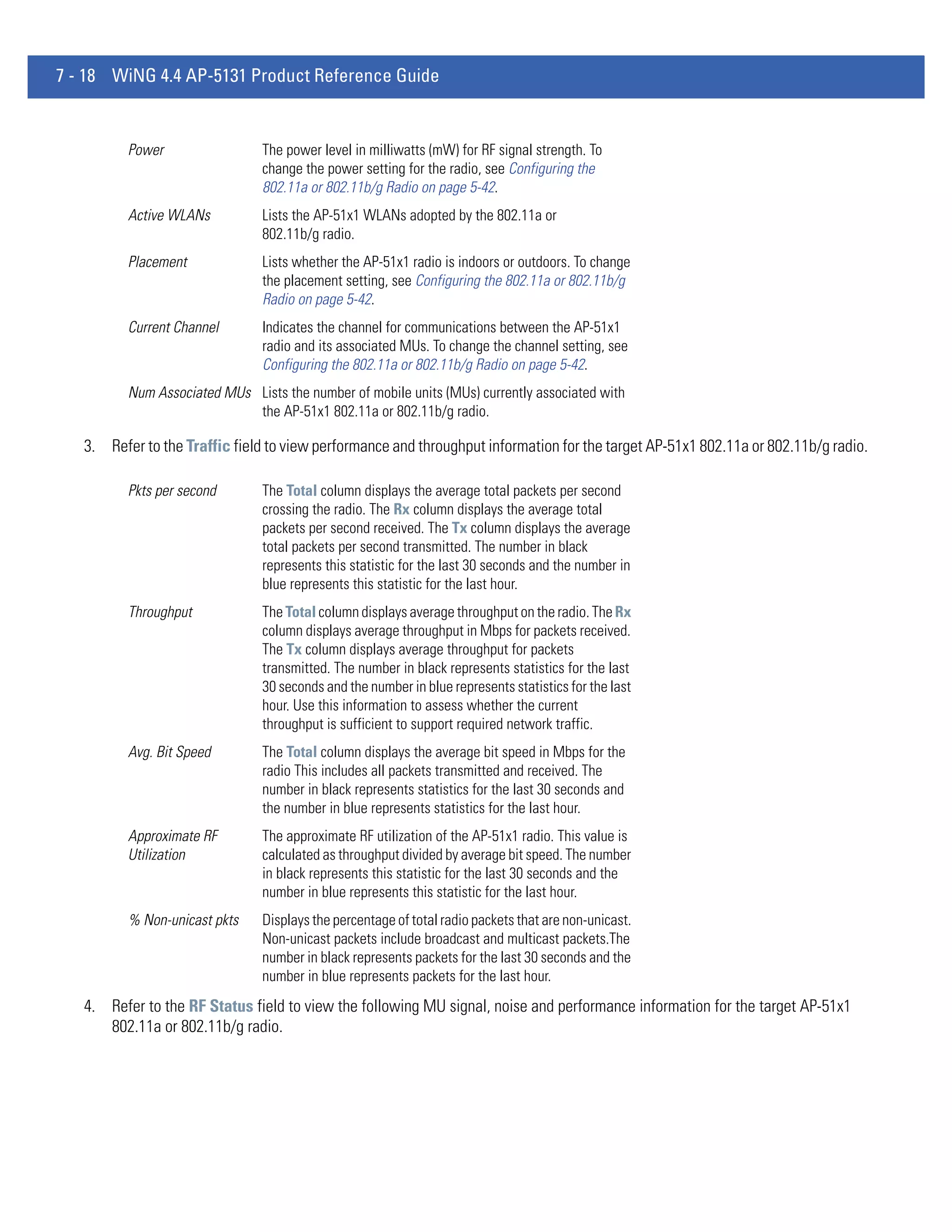
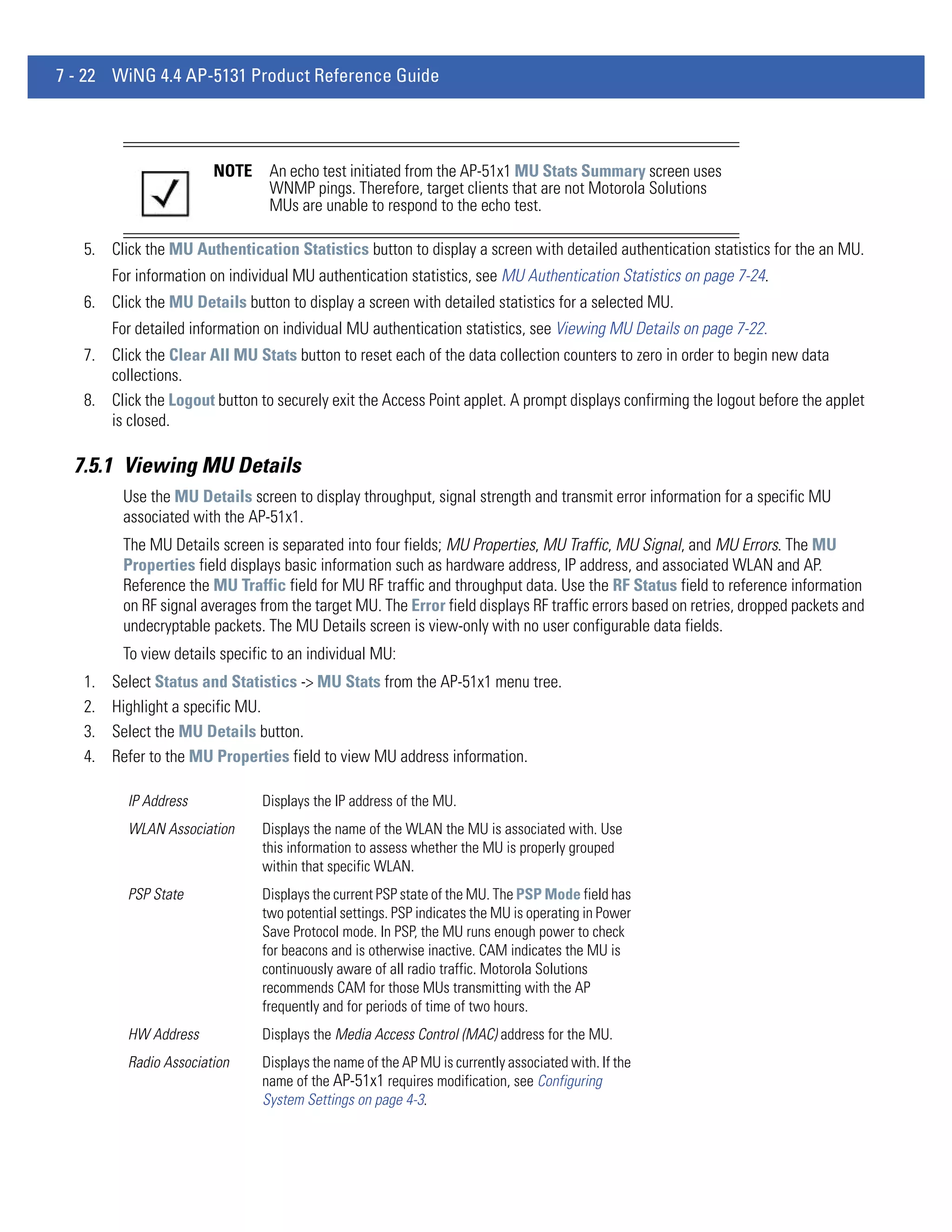
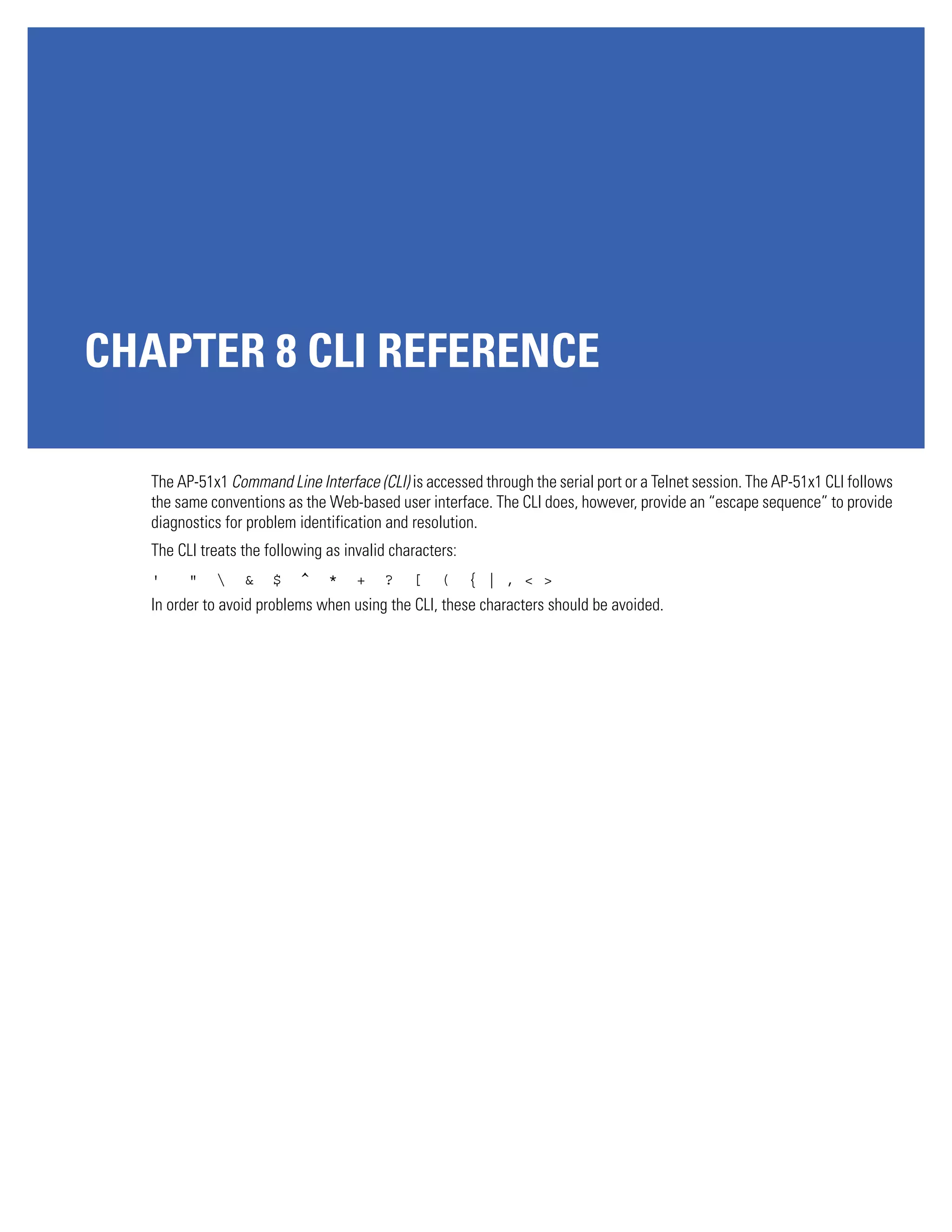
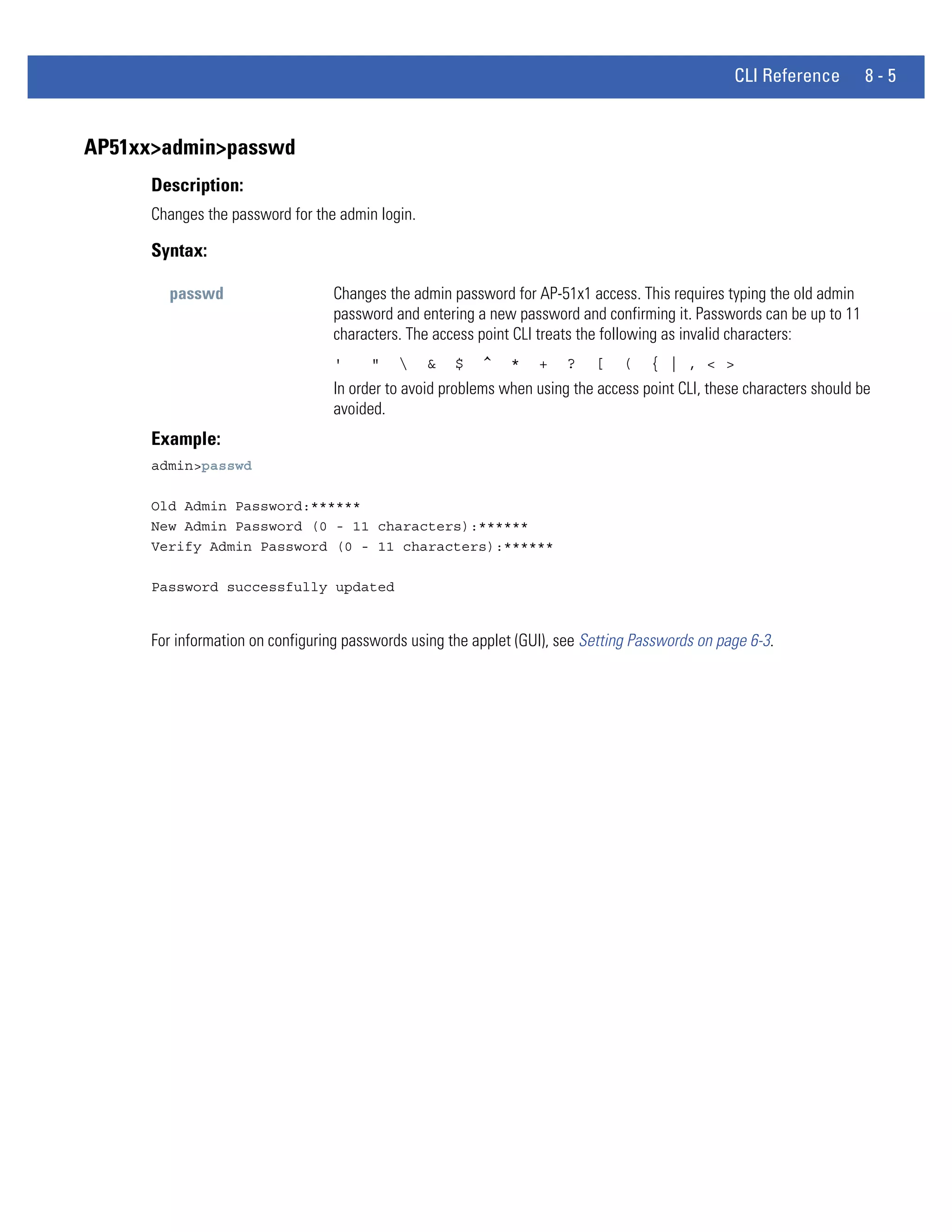
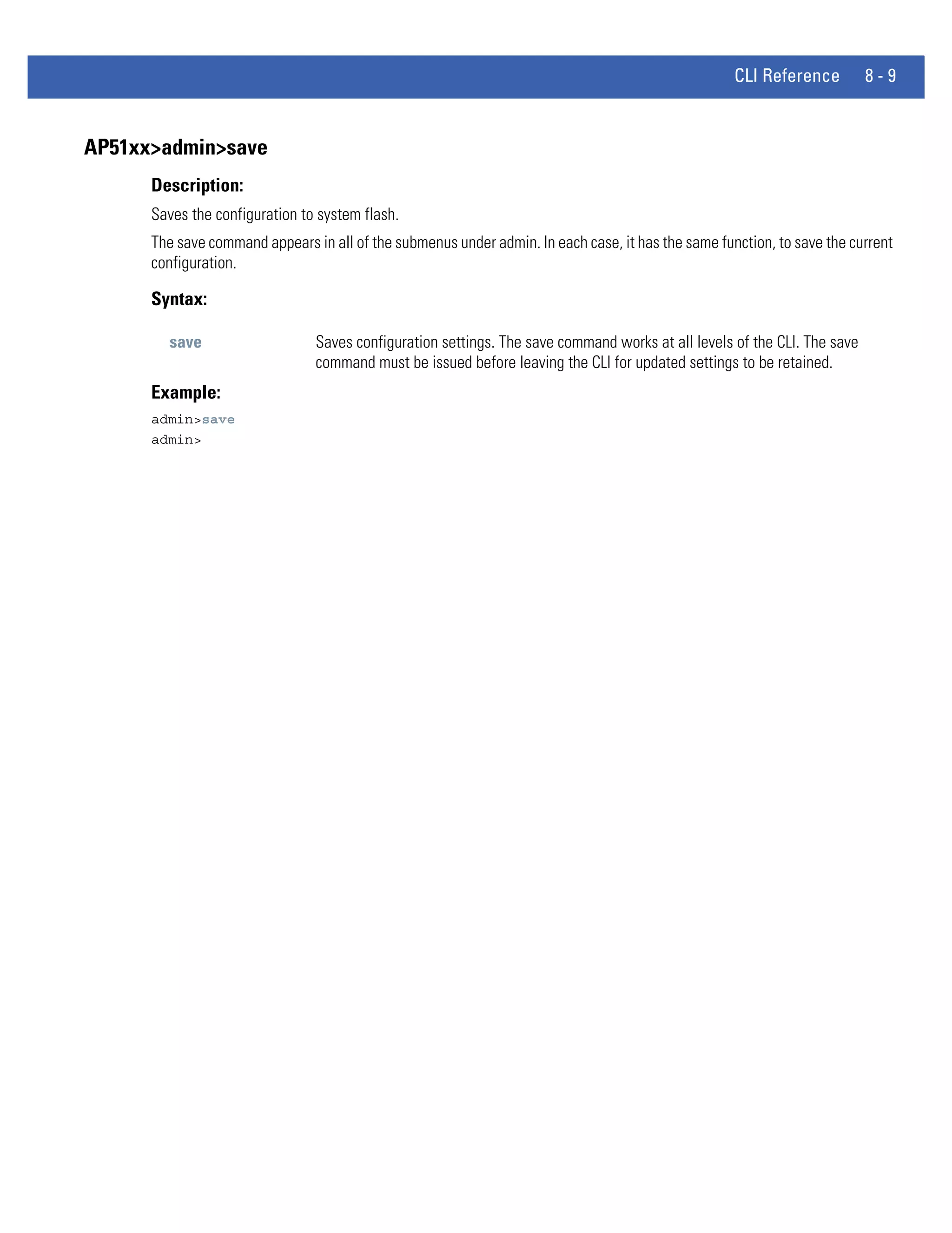
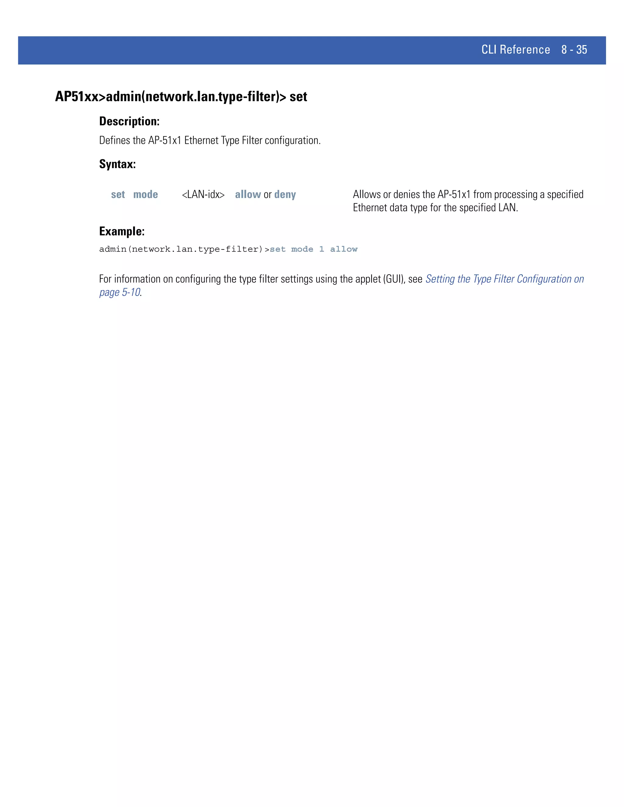
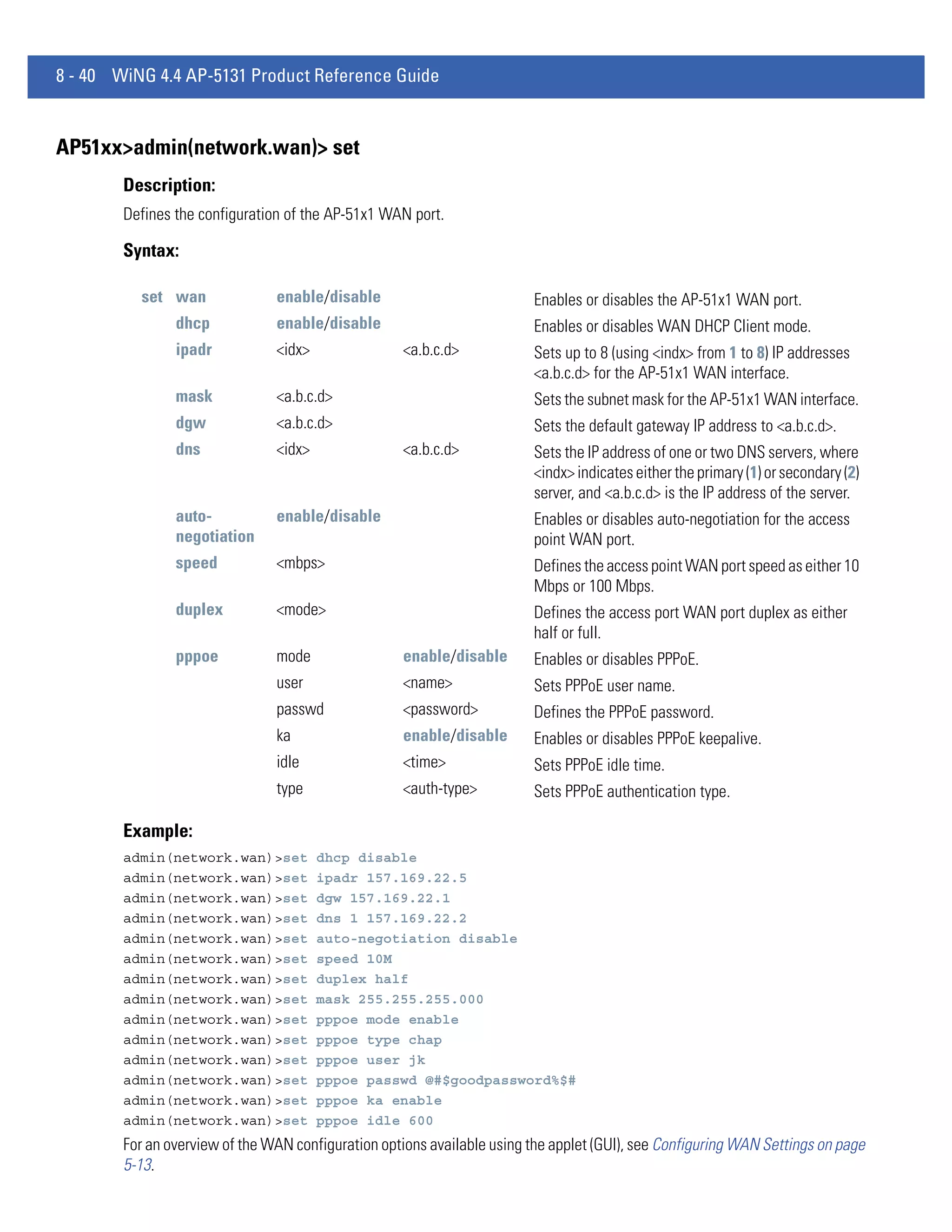
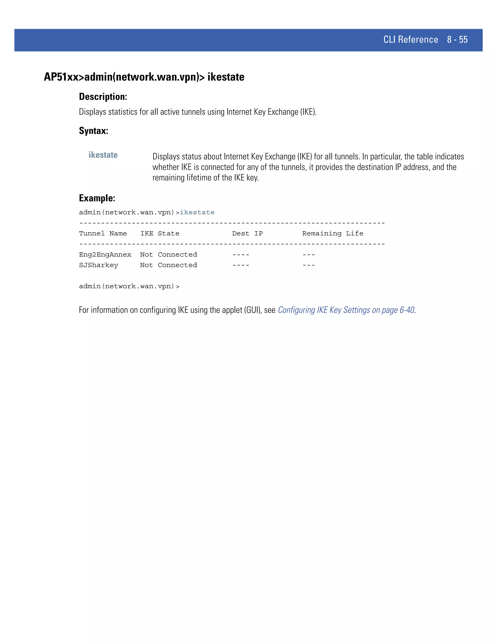
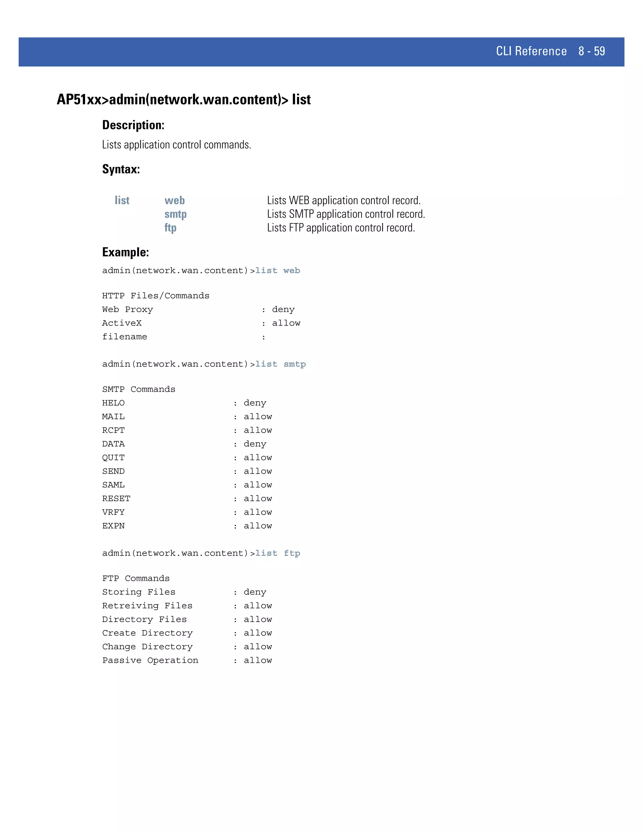
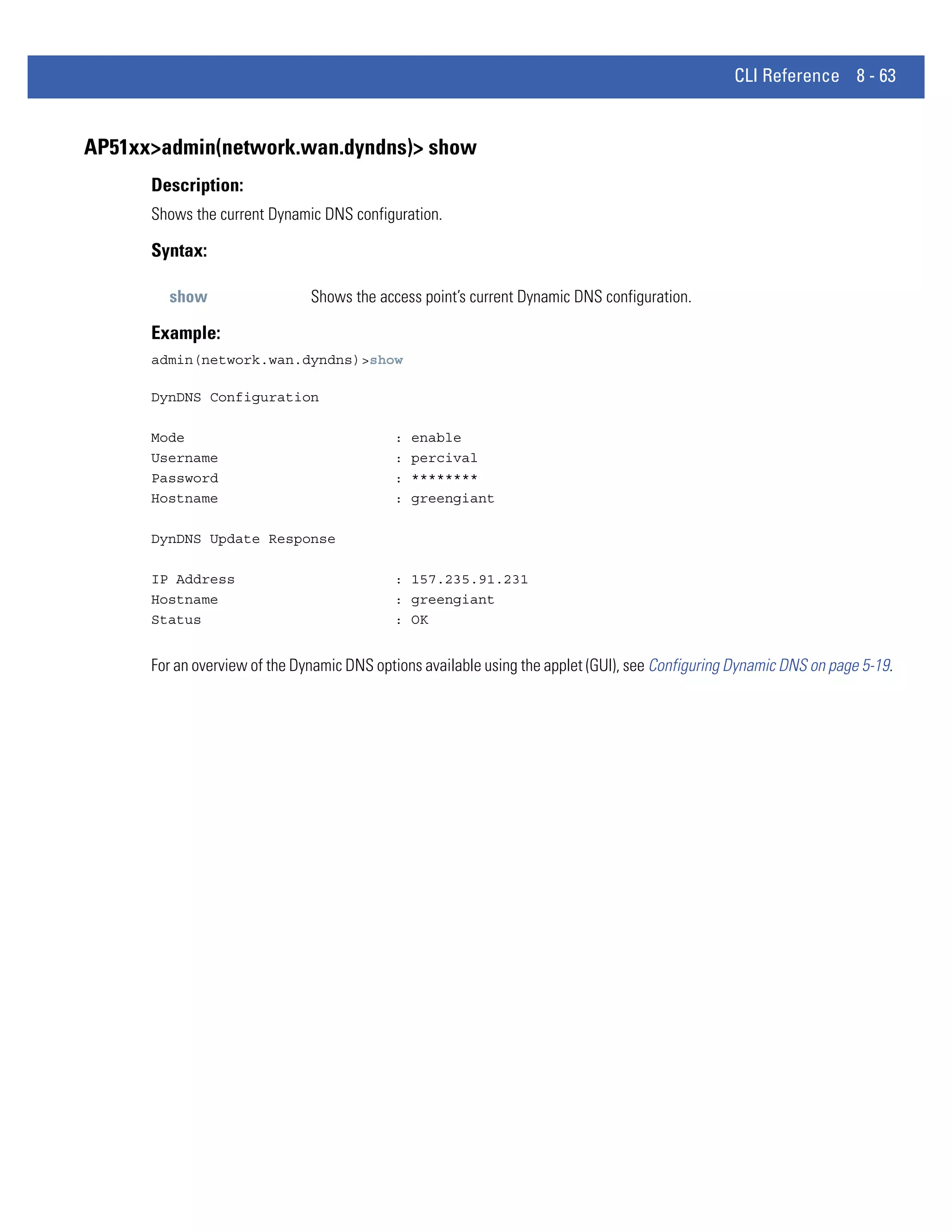
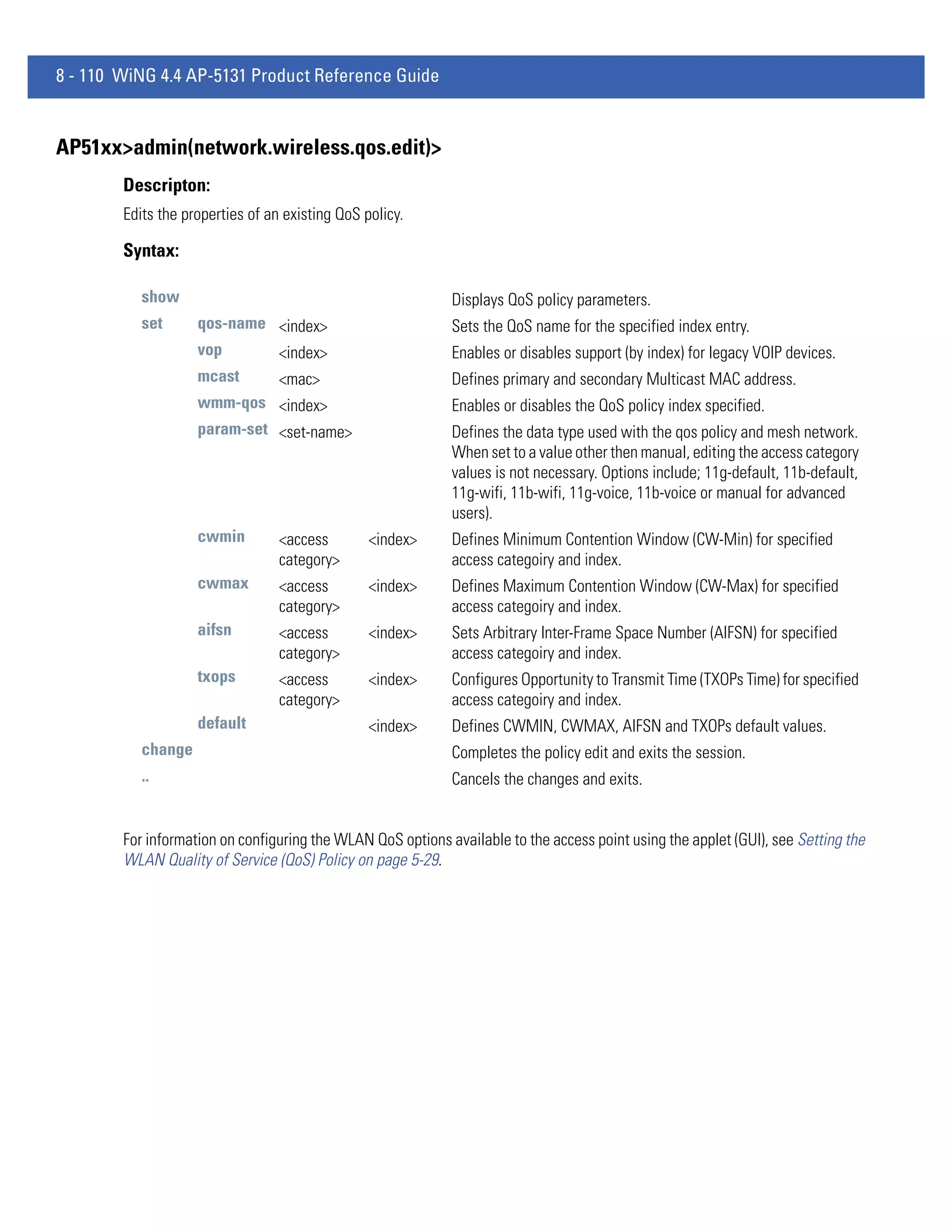
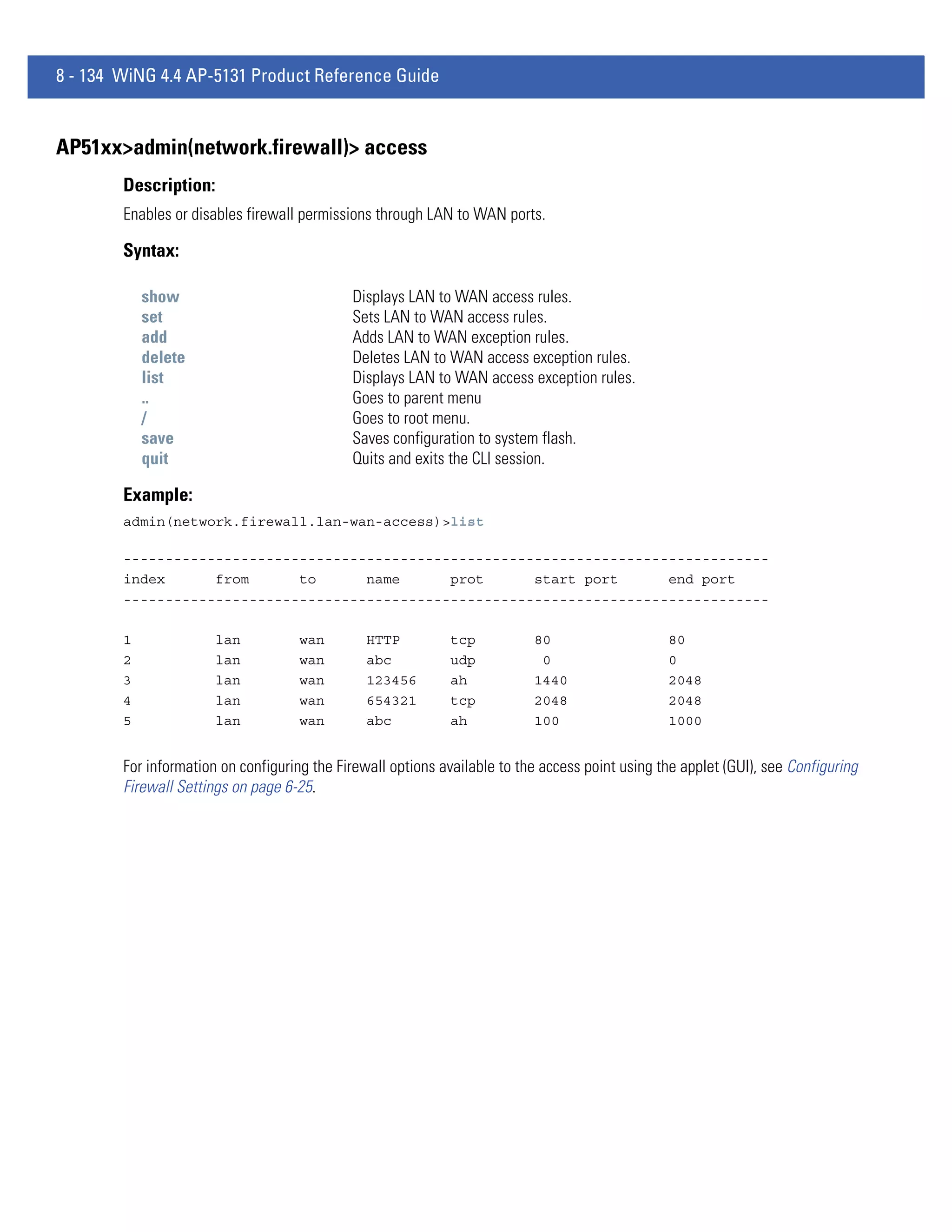
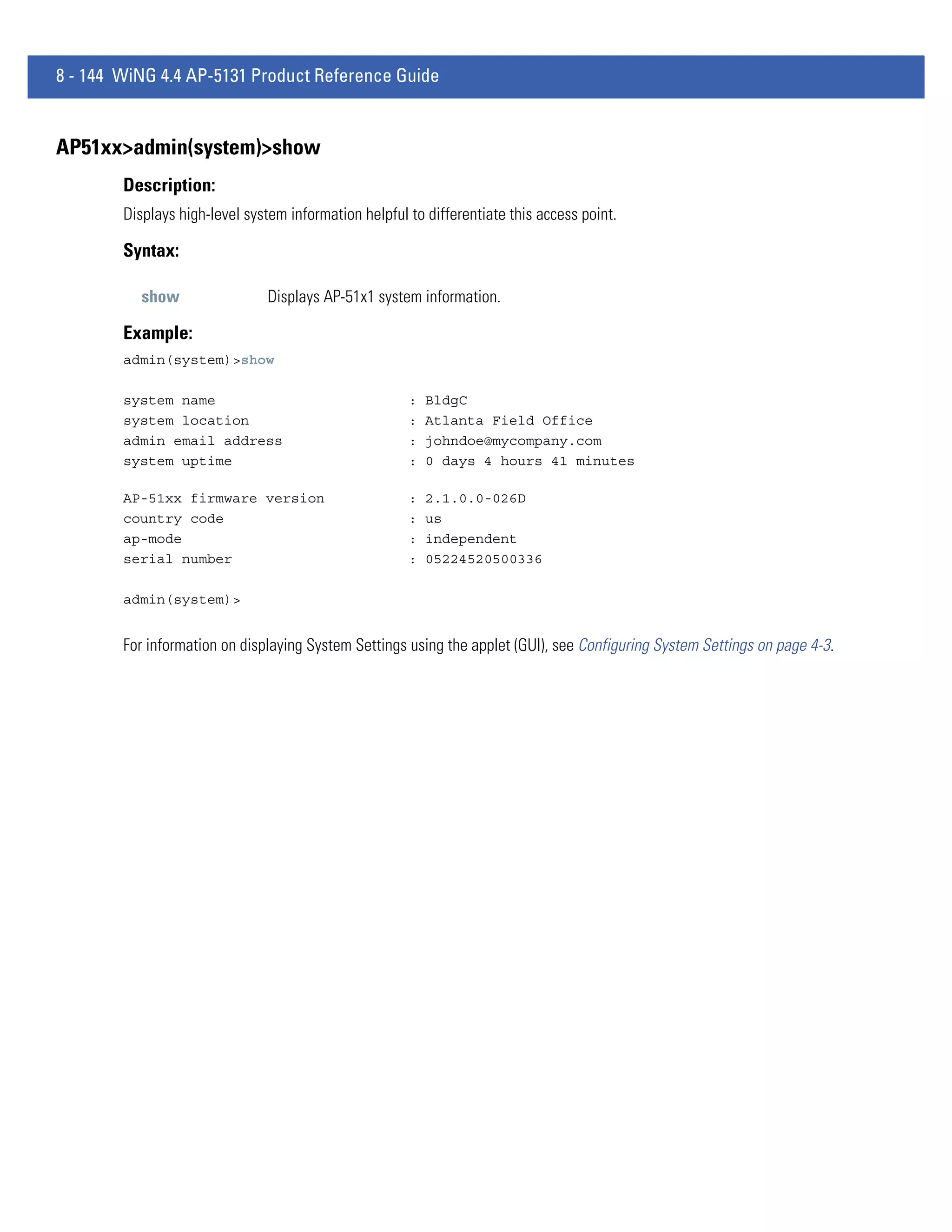
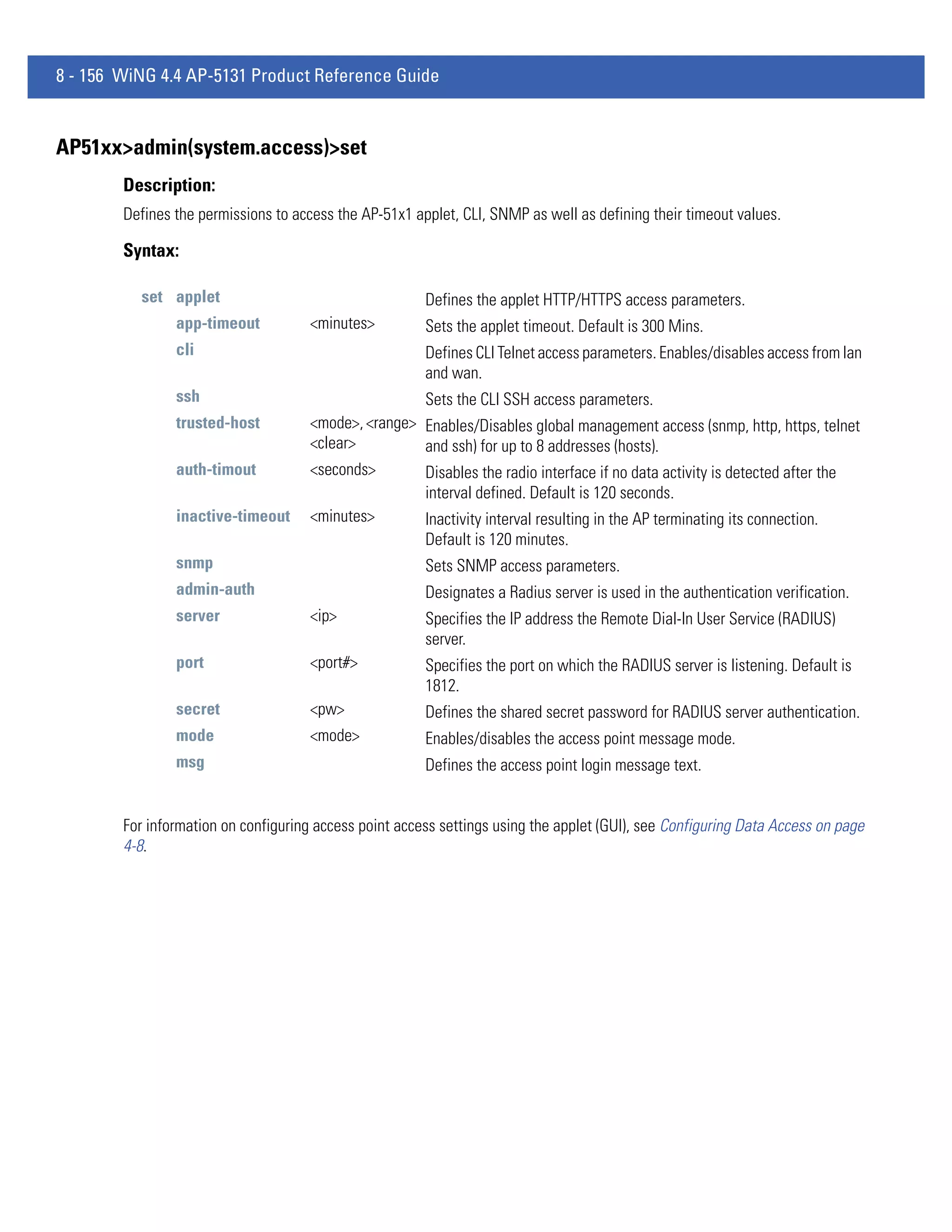
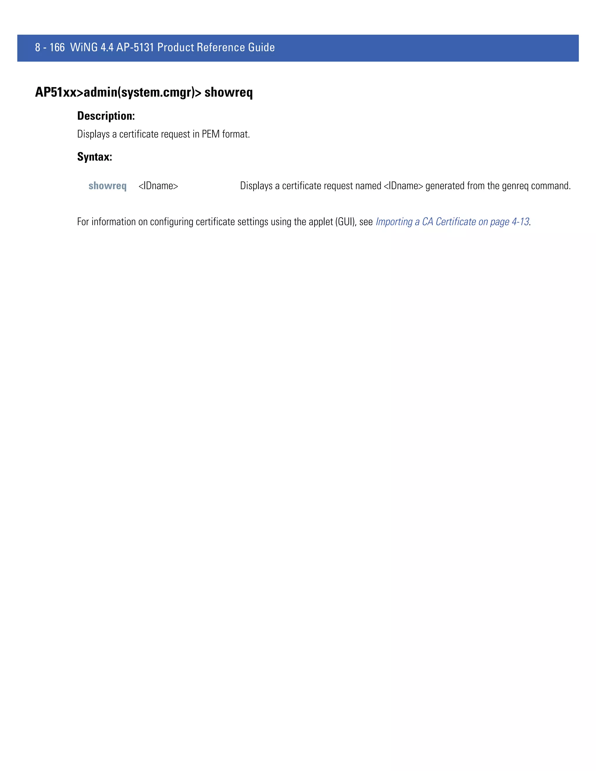
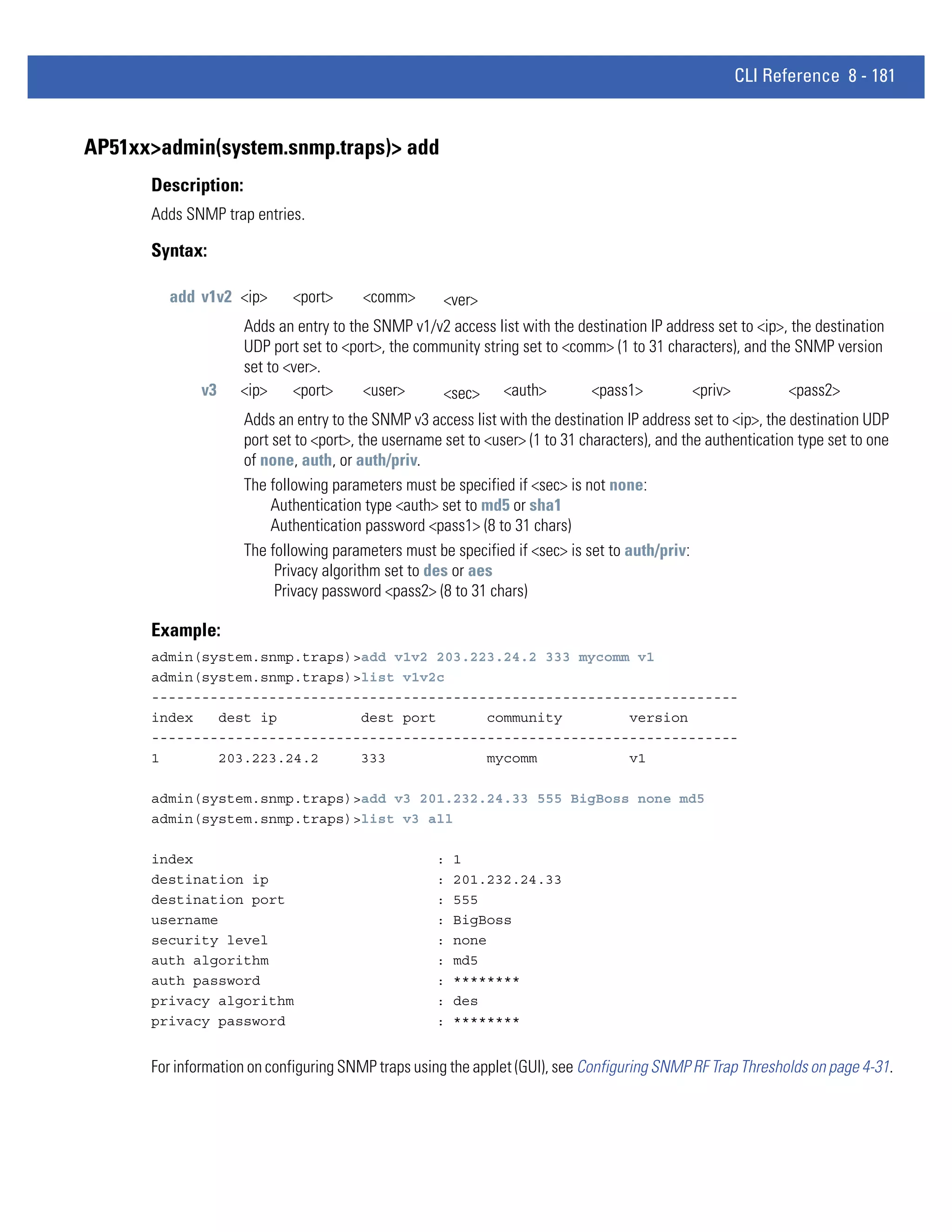
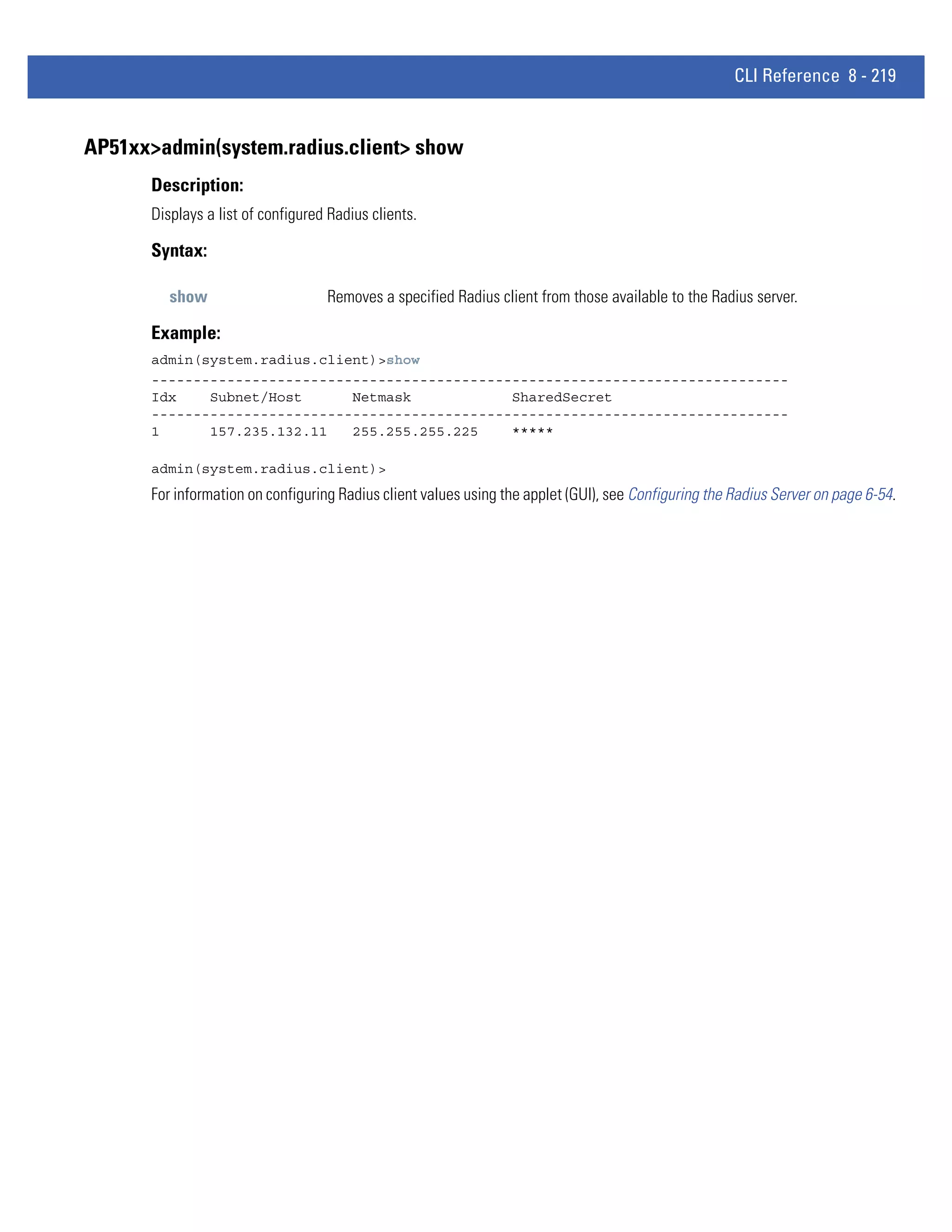
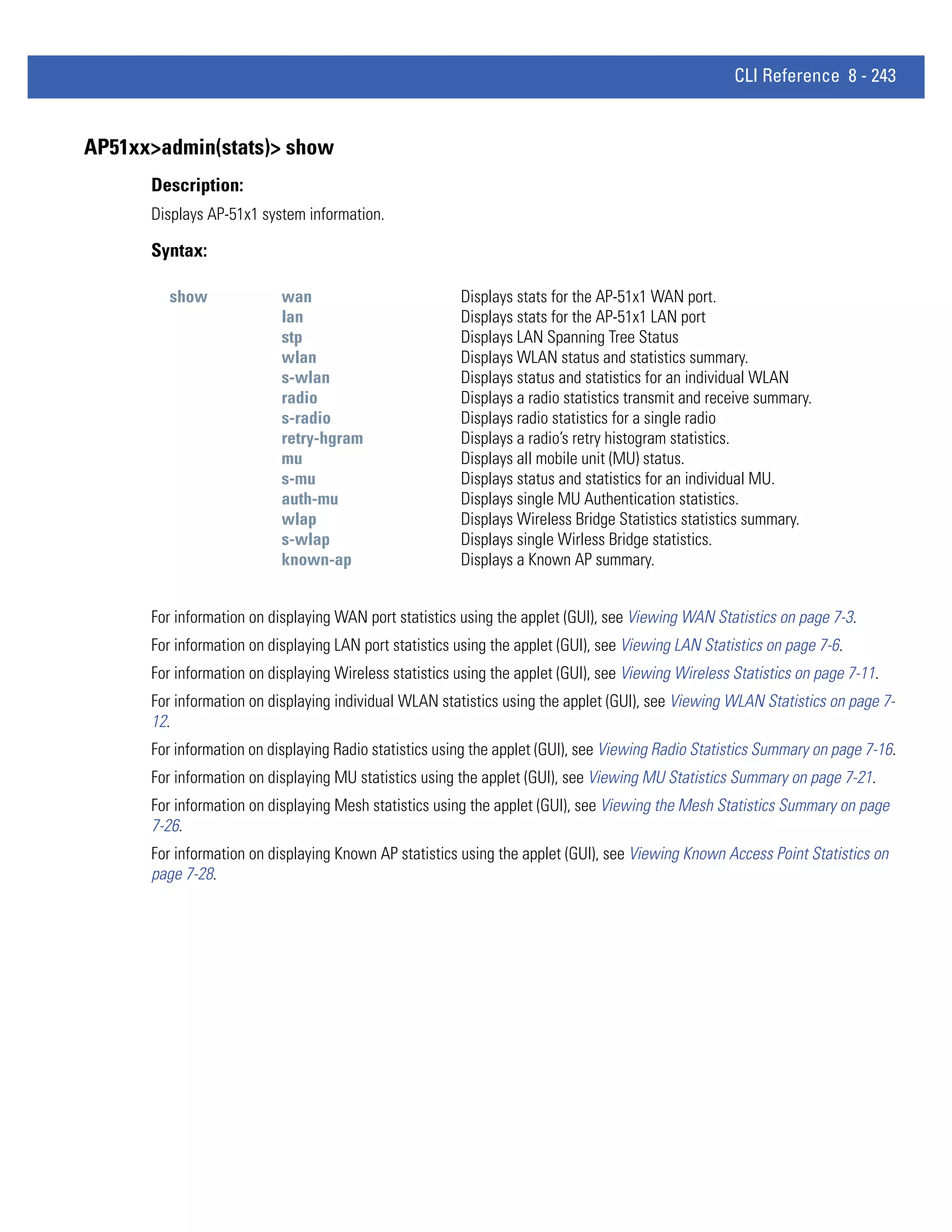
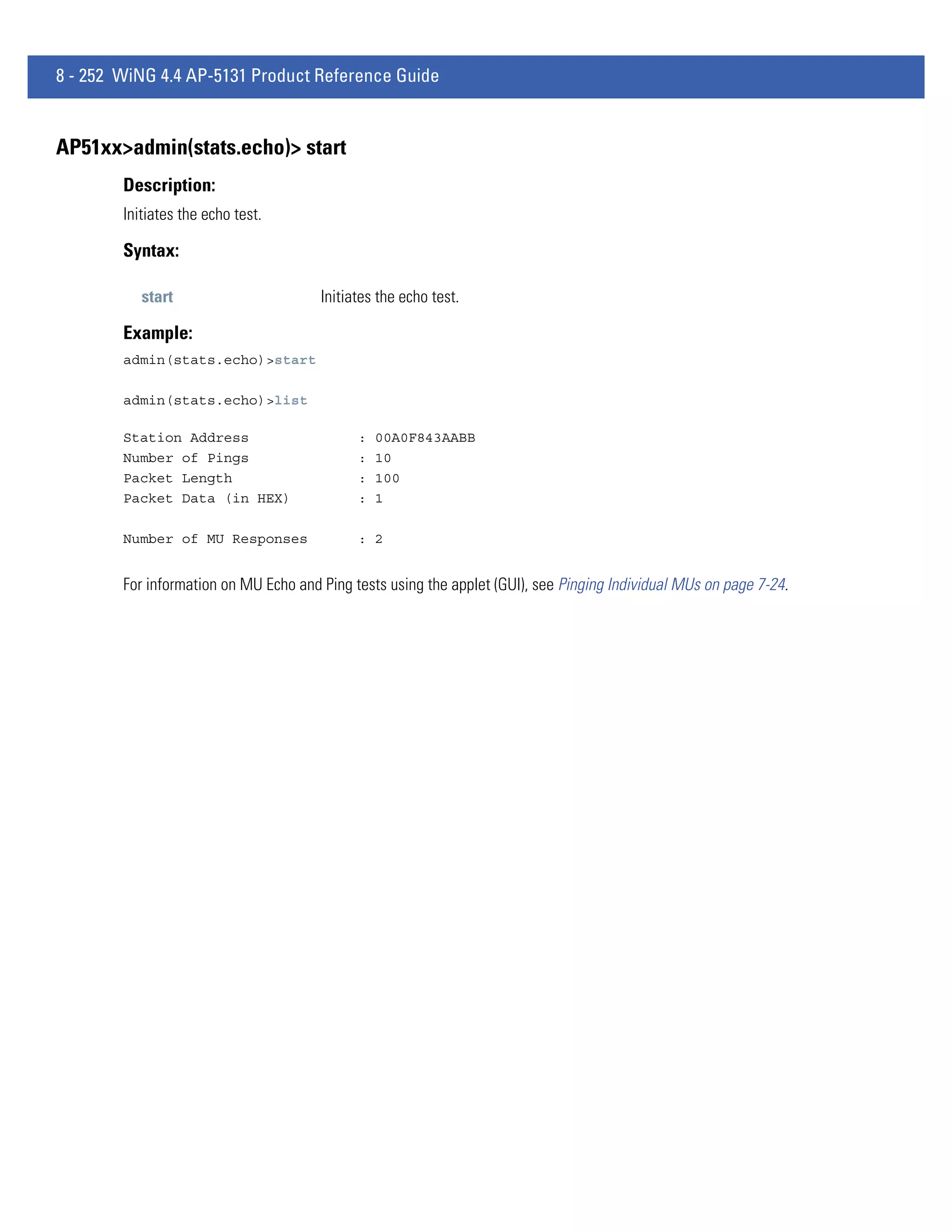
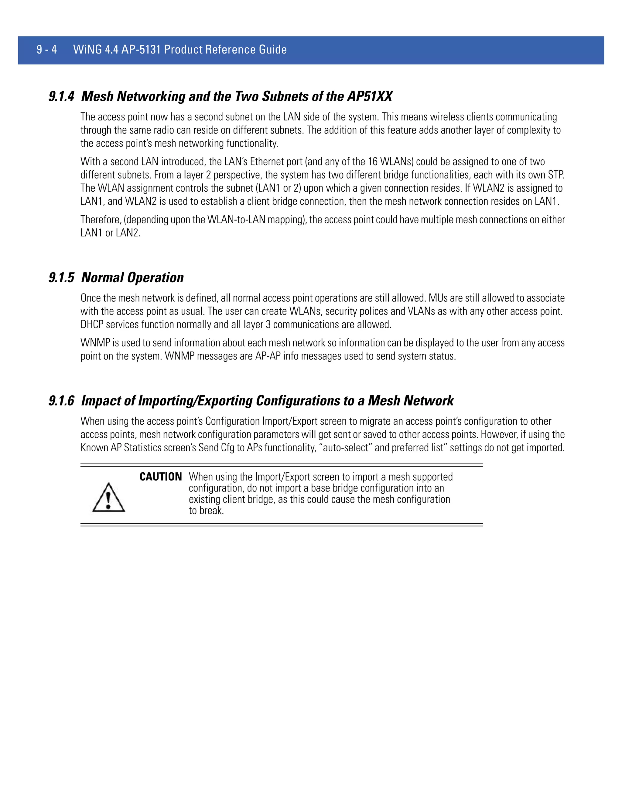
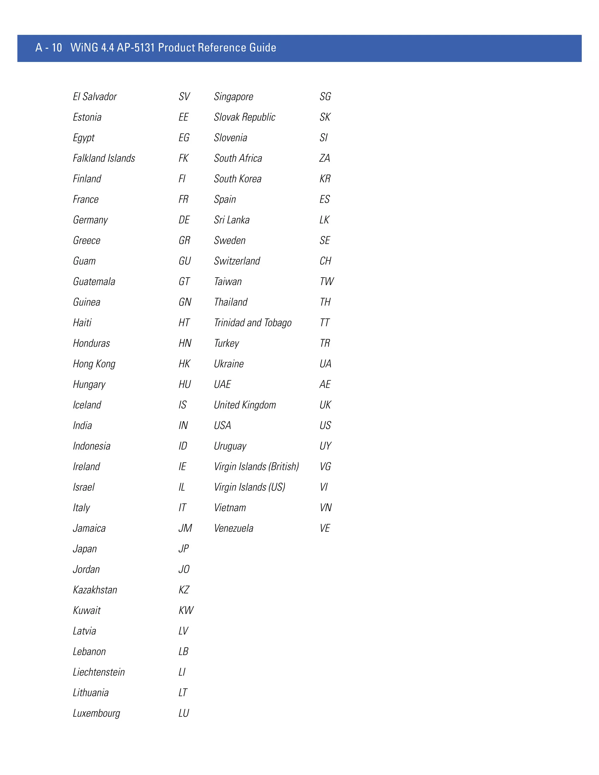
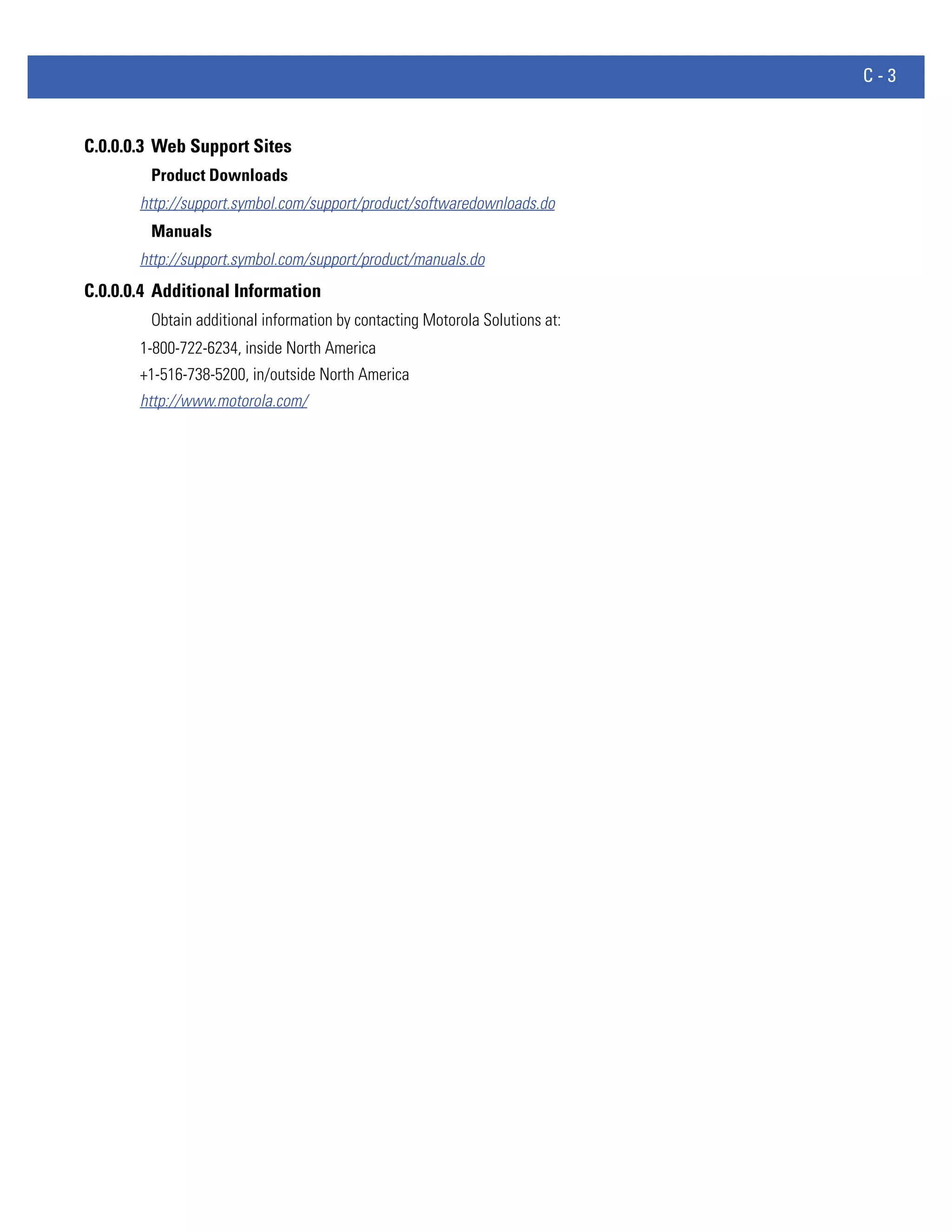
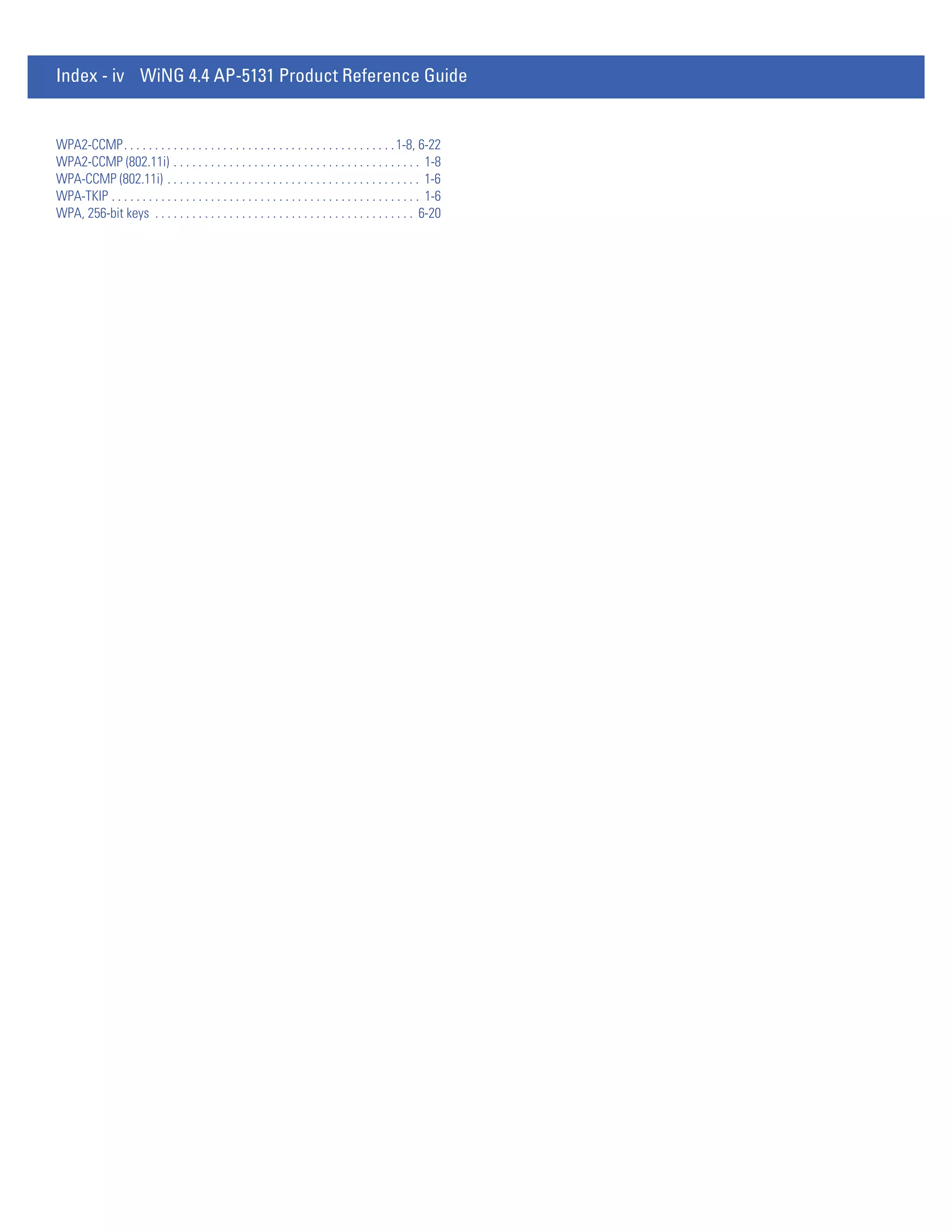
AP51xx>admin(system.cmgr)> genreq
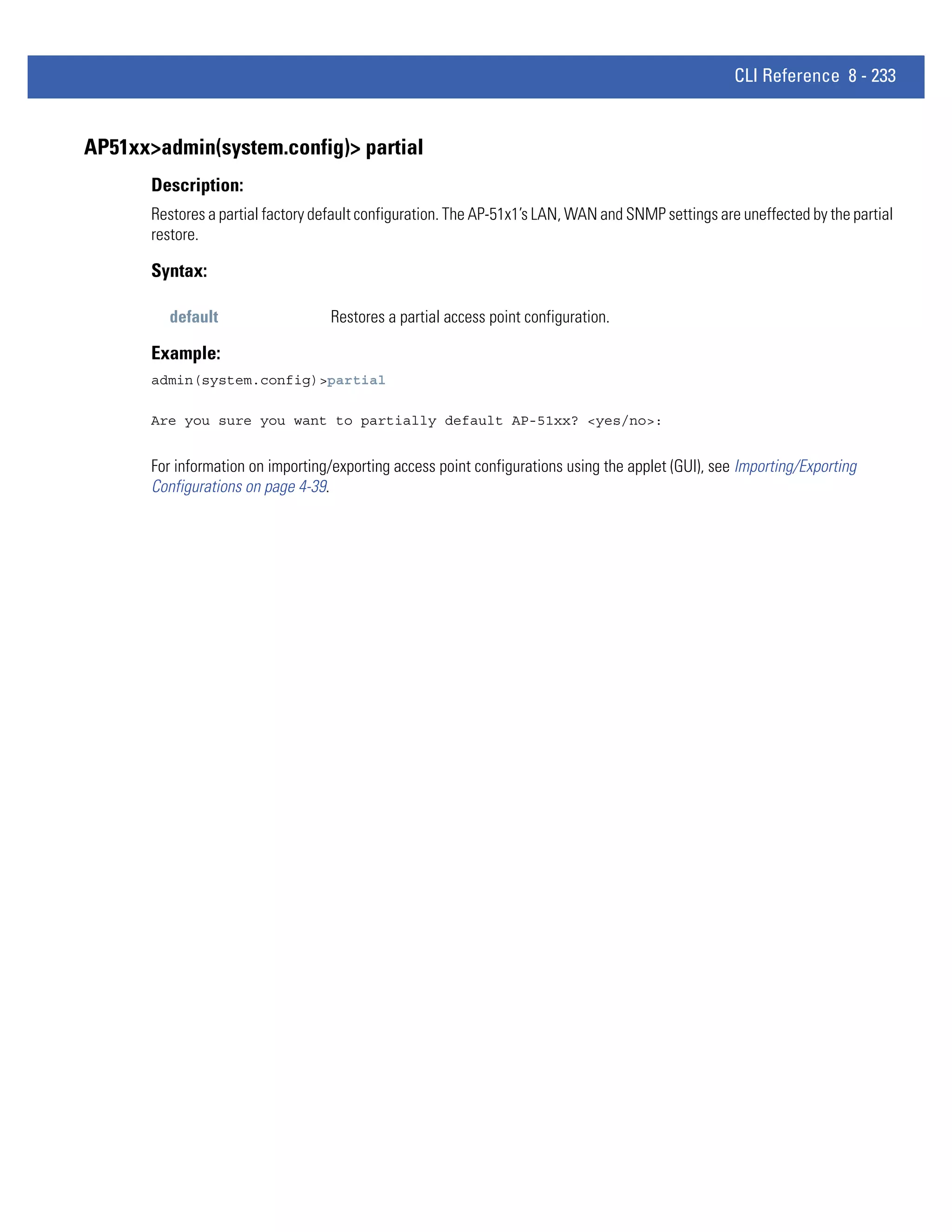
Description:
Generates a certificate request.
Syntax:
genreq <IDname> <Subject> [-ou <OrgUnit>] [-on <OrgName>] [-cn <City>] [-st <State>] . . .
[-p <PostCode>] [-cc <CCode>] [-e <Email>] [-d <Domain>] [-i <IP>] [-sa
<SAlgo>]
Generates a self-certificate request for a Certification Authority (CA), where:
<IDname> The private key ID Name (up to 7 chars)
<Subject> Subject Name (up to 49 chars)
-ou Organization Unit (up to 49 chars)
<Department> Organization Name (up to 49 chars)
-on <OrgName> City Name of Organization (up to 49 chars)
-cn <City> State Name (up to 49 chars)
-st <State> Postal code (9 digits)
-p <PostCode> Country code (2 chars)
-cc <CCode> E-mail Address (up to 49 chars)
-e <Email> Domain Name (up to 49 chars)
-d <Domain> IP Address (a.b.c.d)
-i <IP> Signature Algorithm (one of MD5-RSA or SHA1-RSA
-sa <SAlgo> Key size in bits (one of 512, 1024, or 2048)
-k <KSize>
NOTE: Note: The parameters in [square brackets] are optional. Check with the CA to determine what fields are necessary. For
example, most CAs require an email address and an IP address, but not the address of the organization.
Example:
admin(system.cmgr)>genreq MyCert2 MySubject -ou MyDept -on MyCompany
Please wait. It may take some time...
Generating the certificate request
Retreiving the certificate request
The certificate request is
-----BEGIN CERTIFICATE REQUEST-----
MIHzMIGeAgEAMDkxEjAQBgNVBAoTCU15Q29tcGFueTEPMA0GA1UECxMGTXlEZXB0
MRIwEAYDVQQDEwlNeVN1YmplY3QwXDANBgkqhkiG9w0BAQEFAANLADBIAkEAtKcX
plKFCFAJymTFX71yuxY1fdS7UEhKjBsH7pdqnJnsASK6ZQGAqerjpKScWV1mzYn4
1q2+mgGnCvaZUlIo7wIDAQABoAAwDQYJKoZIhvcNAQEEBQADQQCClQ5LHdbG/C1f
Bj8AszttSo/bA4dcX3vHvhhJcmuuWO9LHS2imPA3xhX/d6+Q1SMbs+tG4RP0lRSr
iWDyuvwx
-----END CERTIFICATE REQUEST-----
For information on configuring certificate management settings using the applet (GUI), see Managing Certificate Authority
(CA) Certificates on page 4-13.](https://image.slidesharecdn.com/motorolasolutionswing4-4ap51xxaccesspointproductreferenceguidepartno-72e-157066-01rev-a-120807142110-phpapp02/75/Motorola-solutions-wing-4-4-ap51xx-access-point-product-reference-guide-part-no-72-e-157066-01-rev-a-429-2048.jpg)


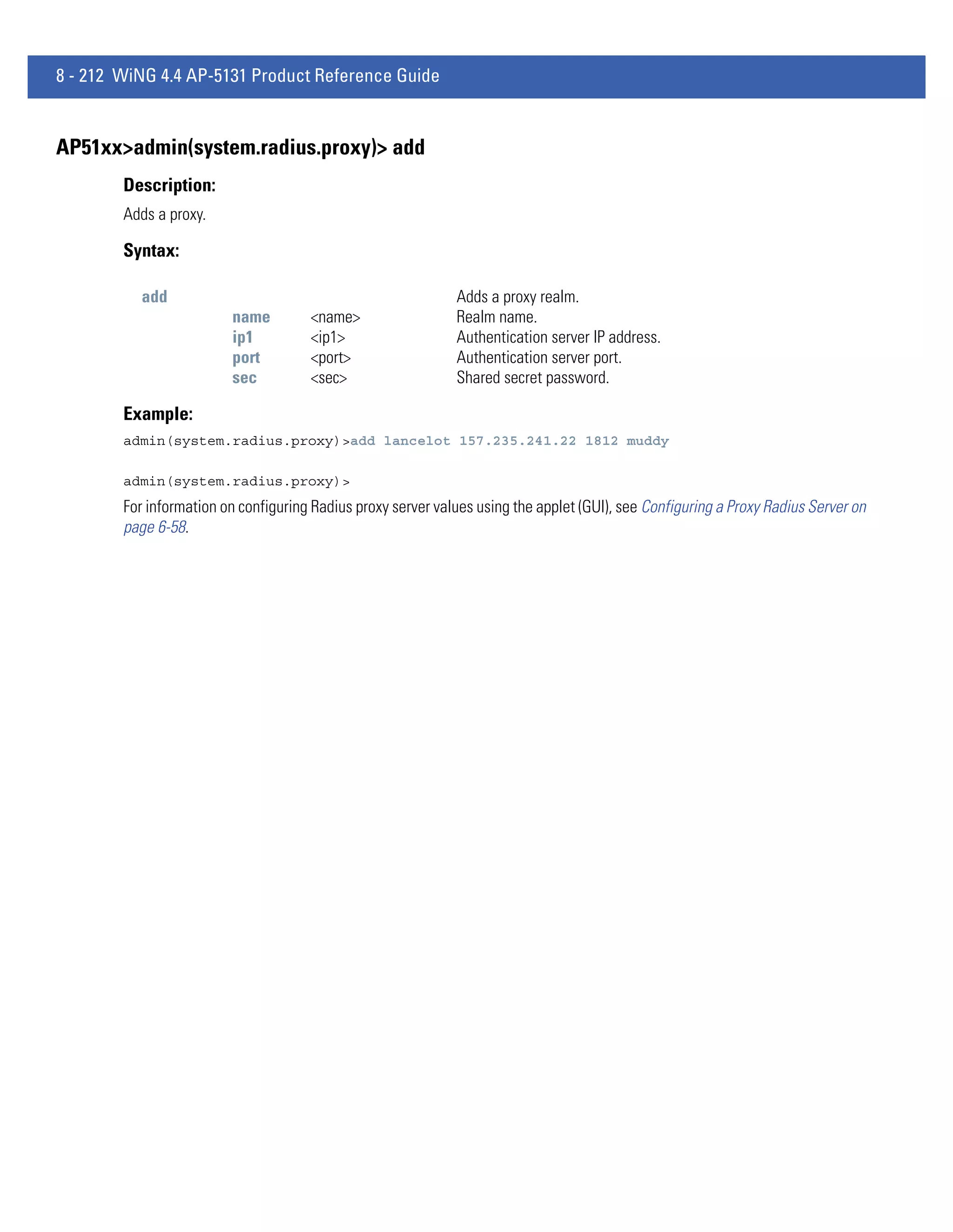
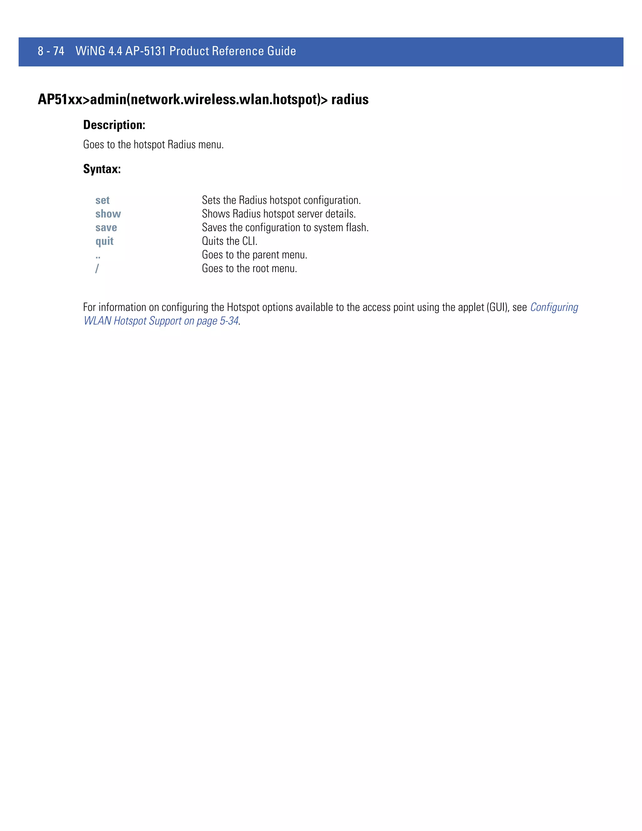
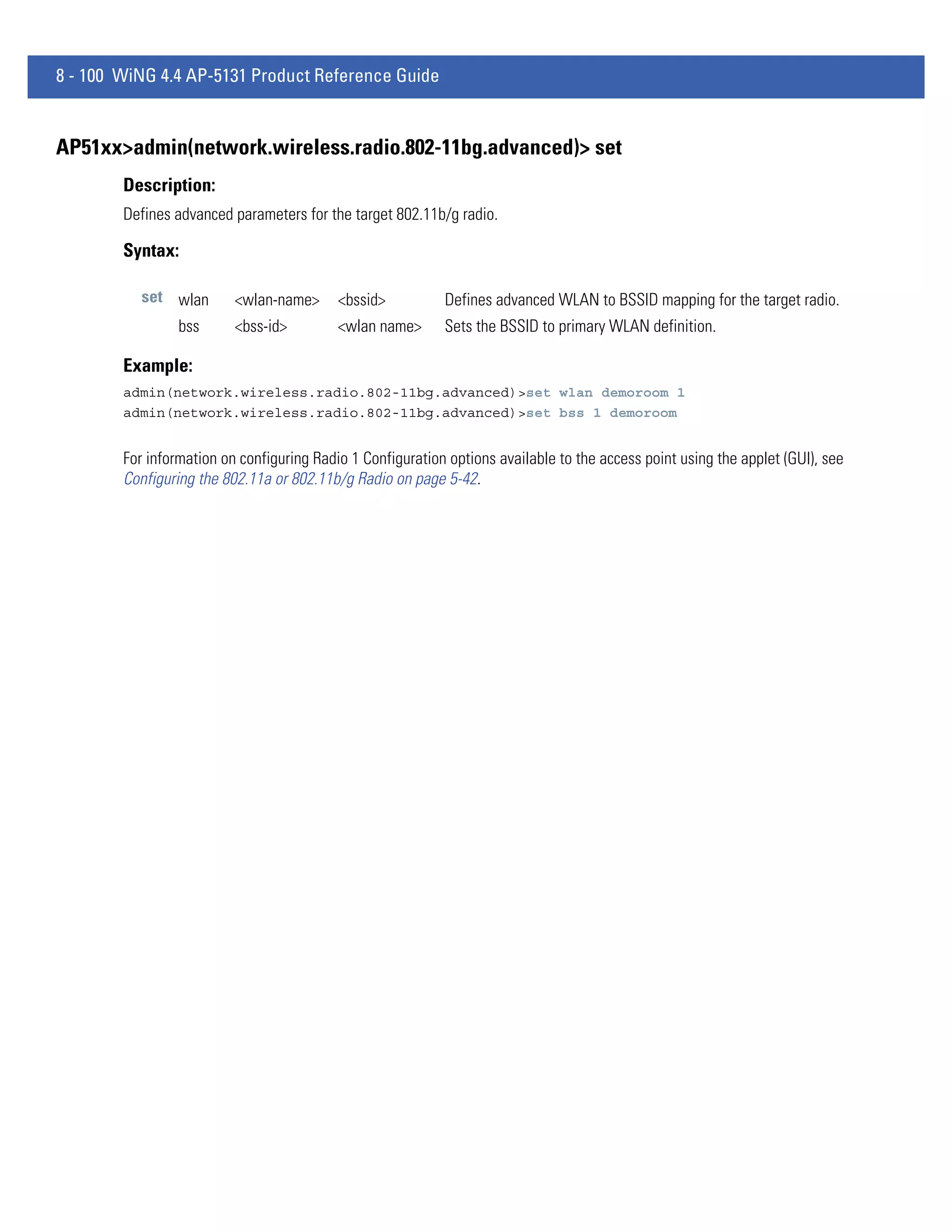
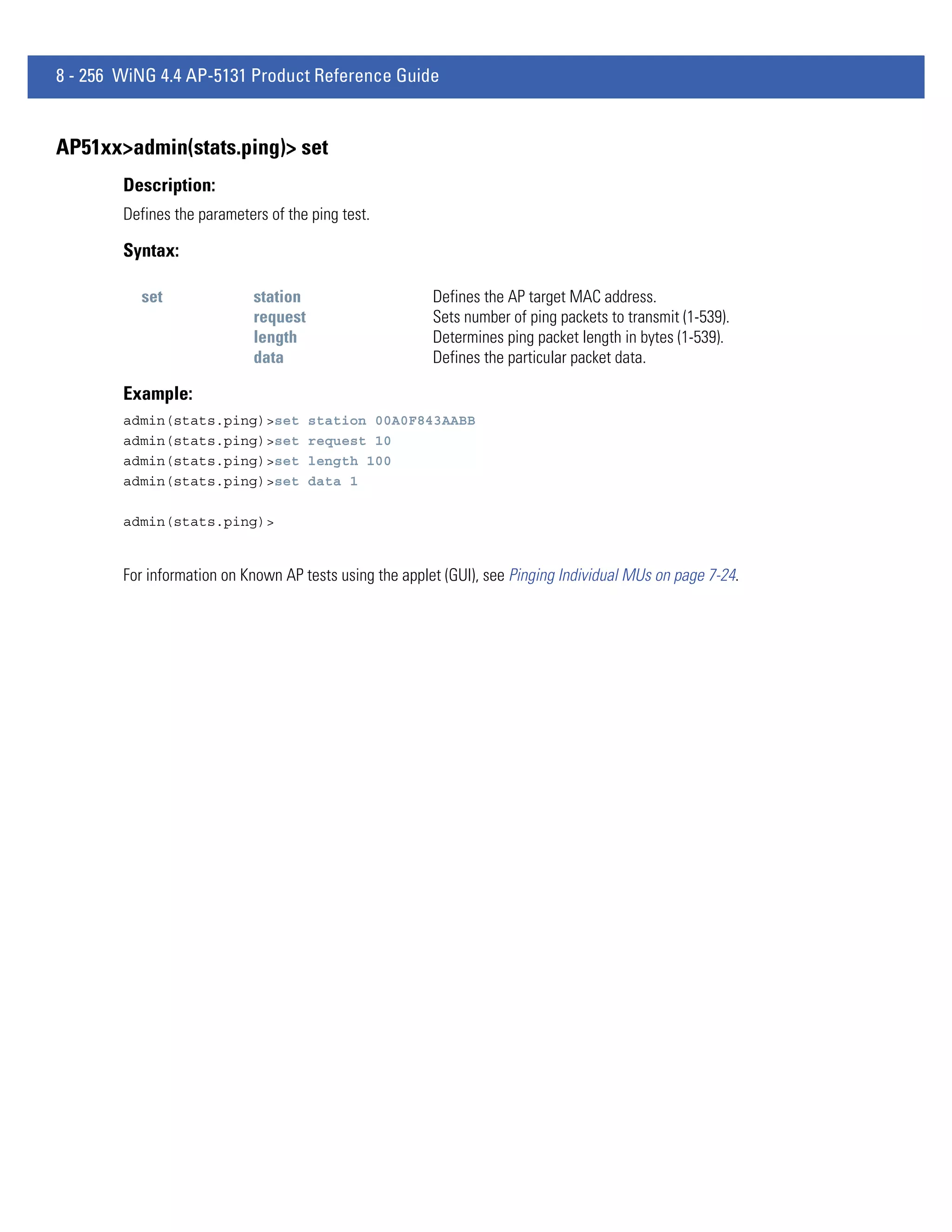
![8 - 224 WiNG 4.4 AP-5131 Product Reference Guide
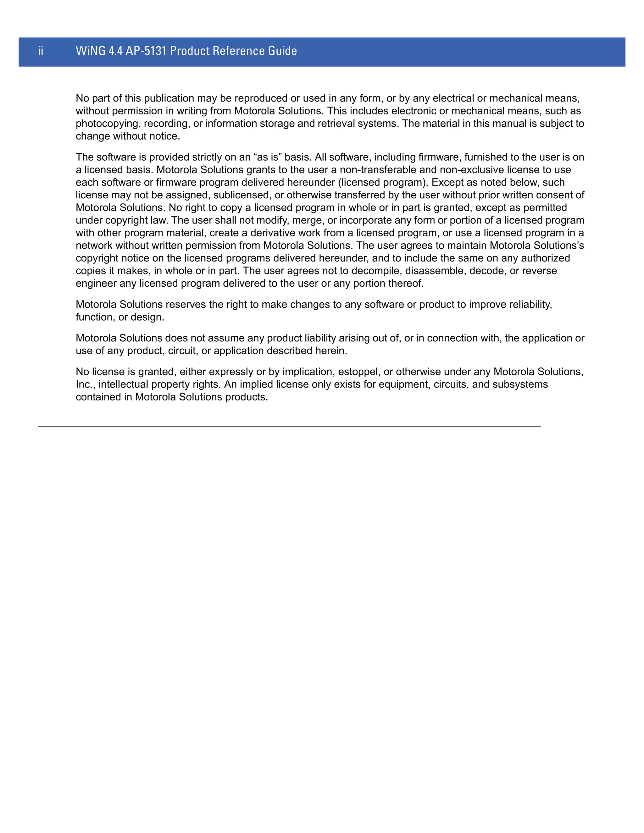
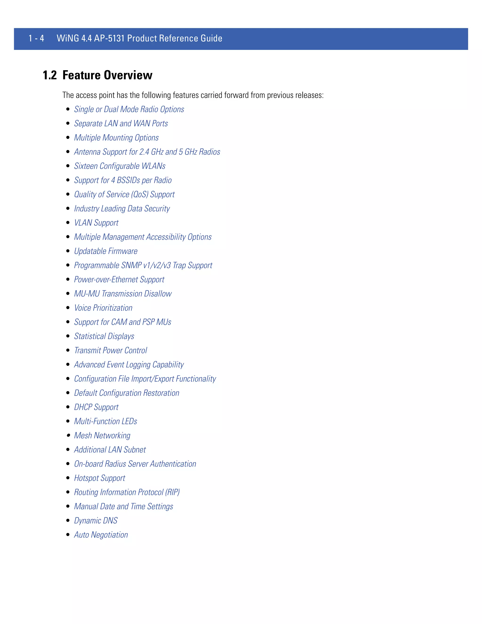
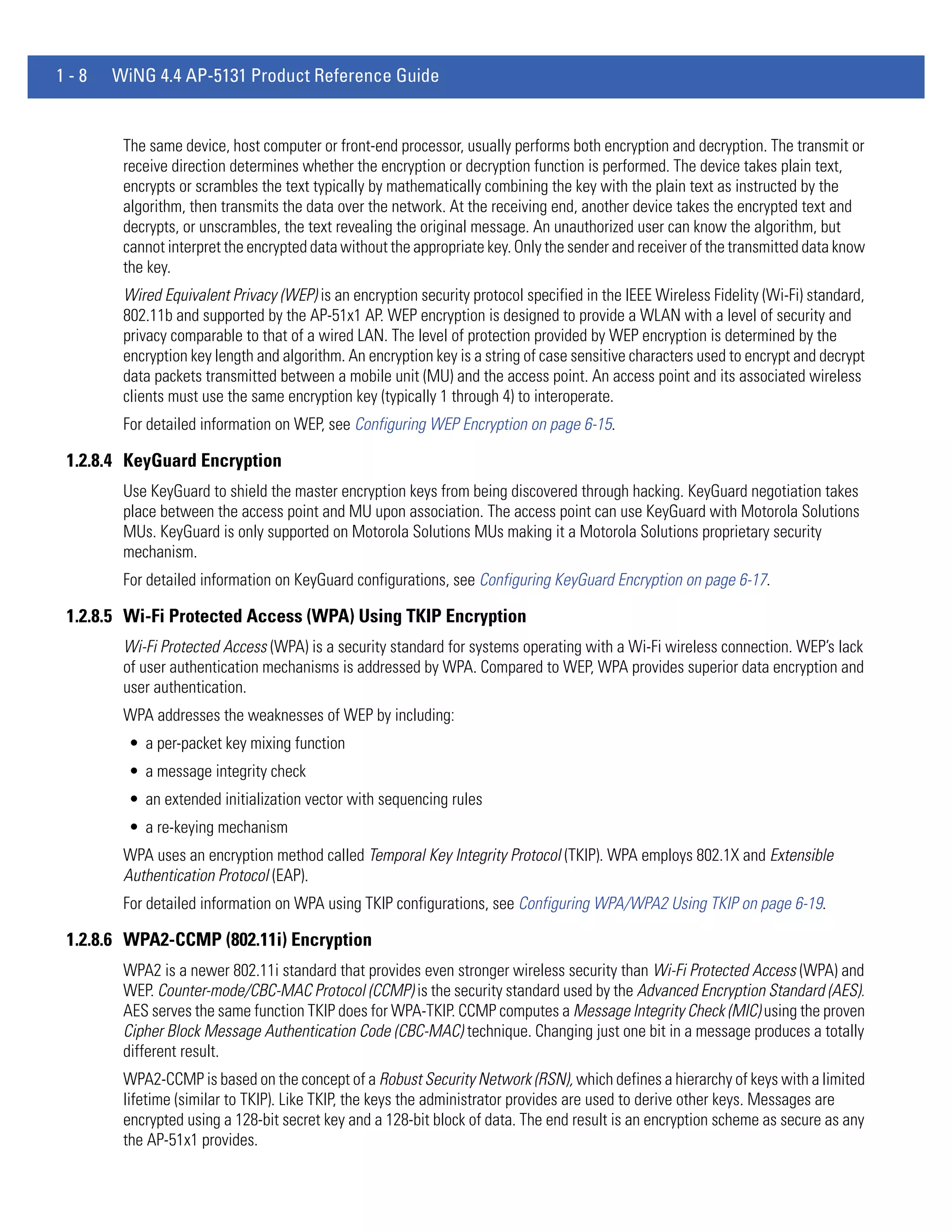
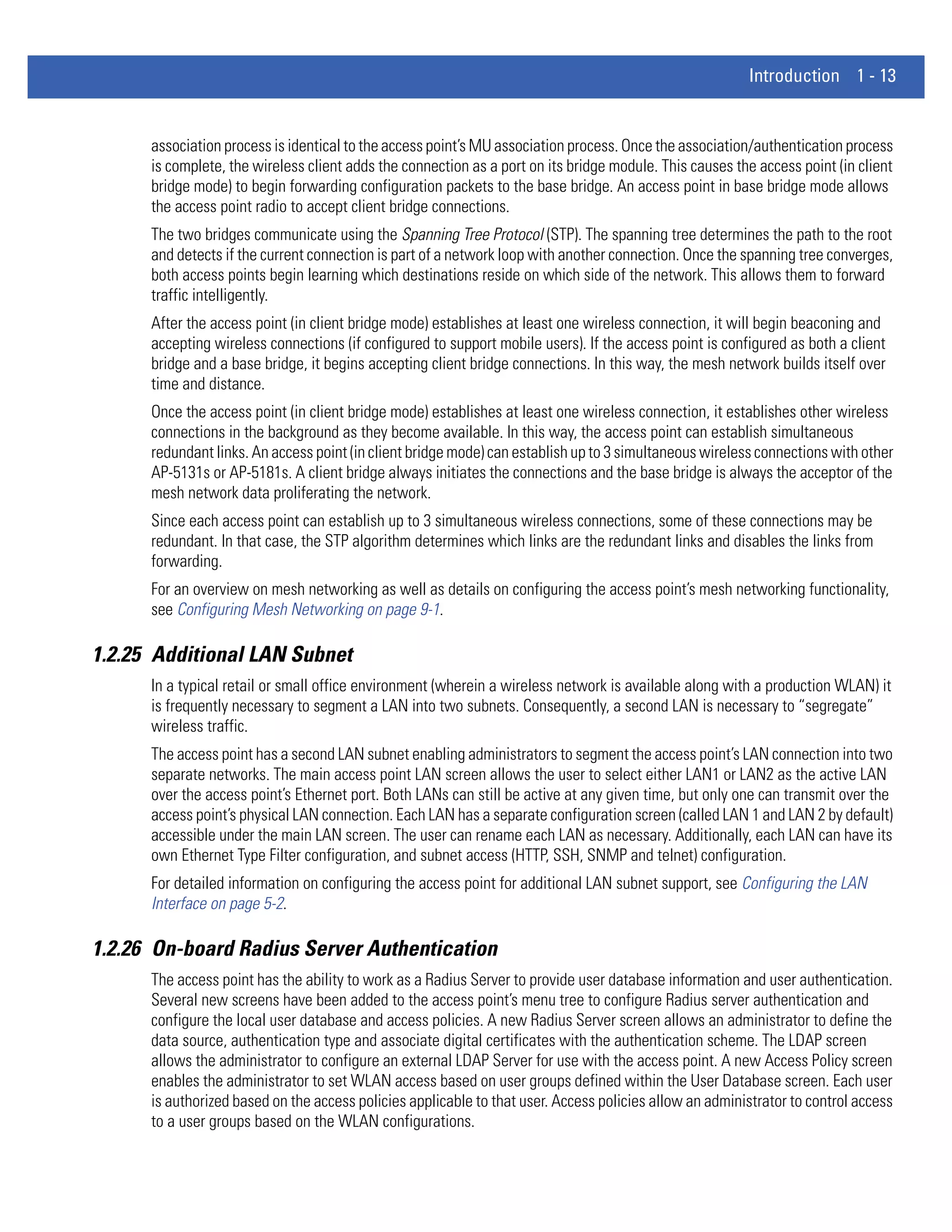
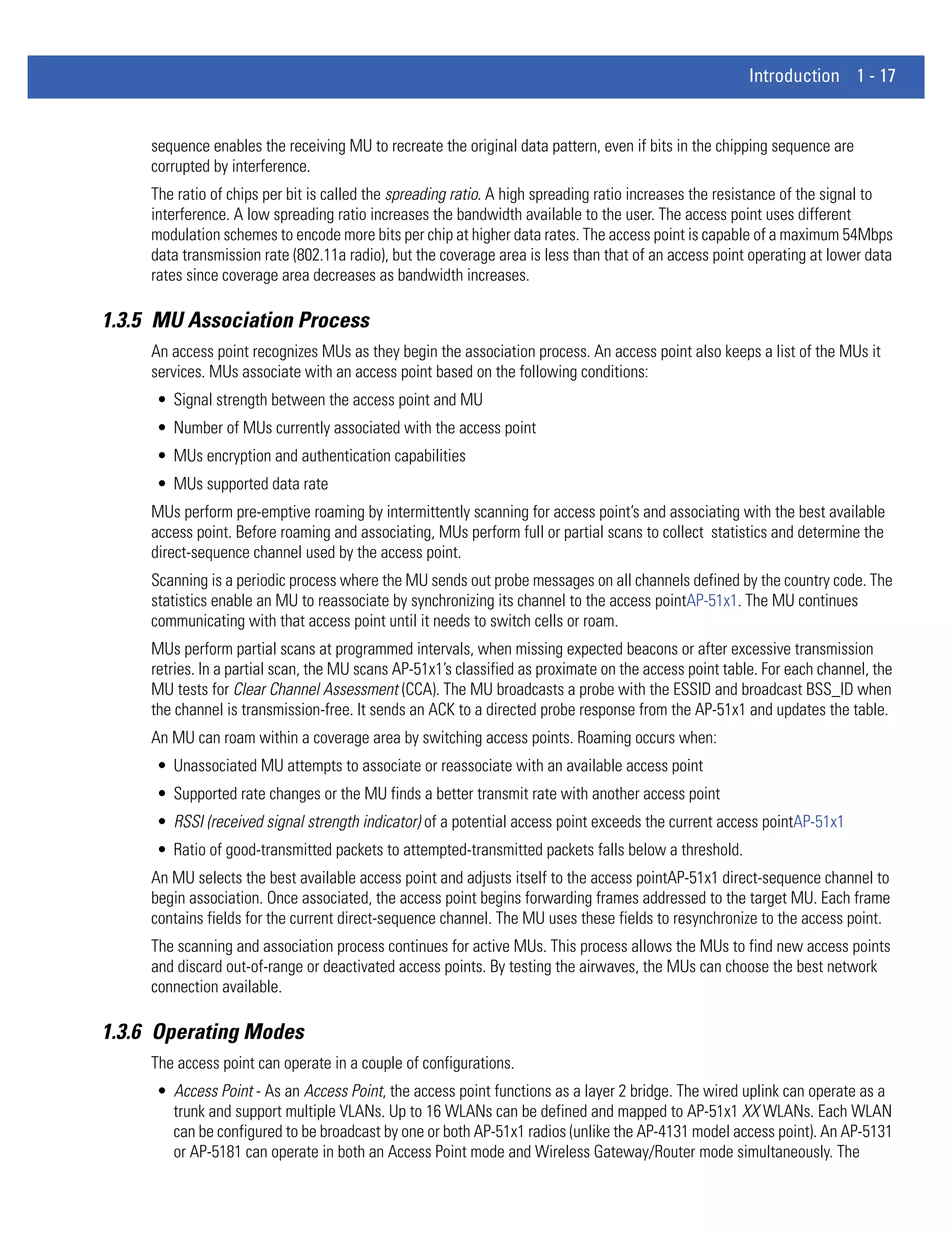
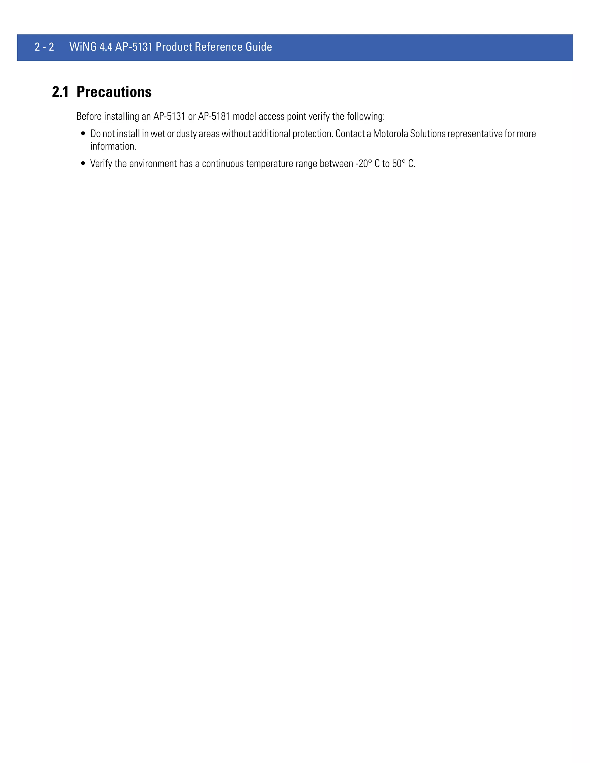
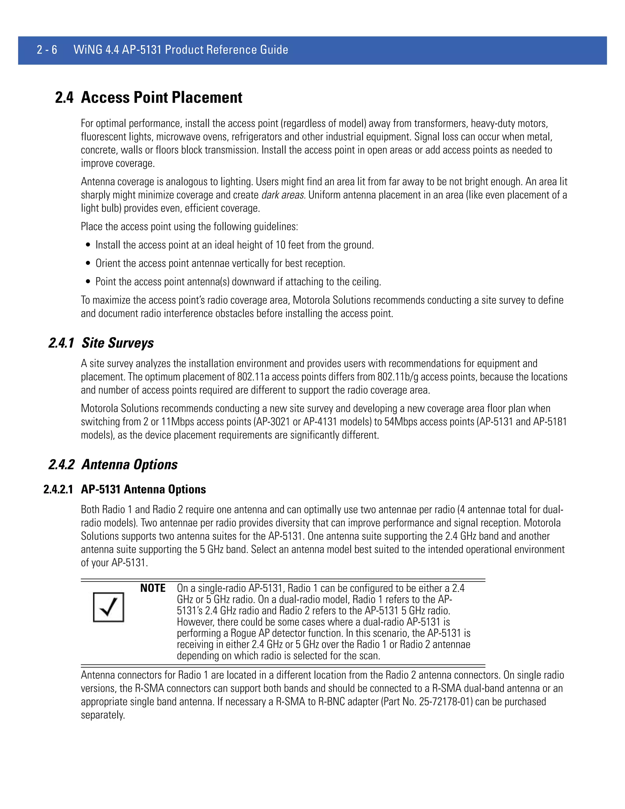
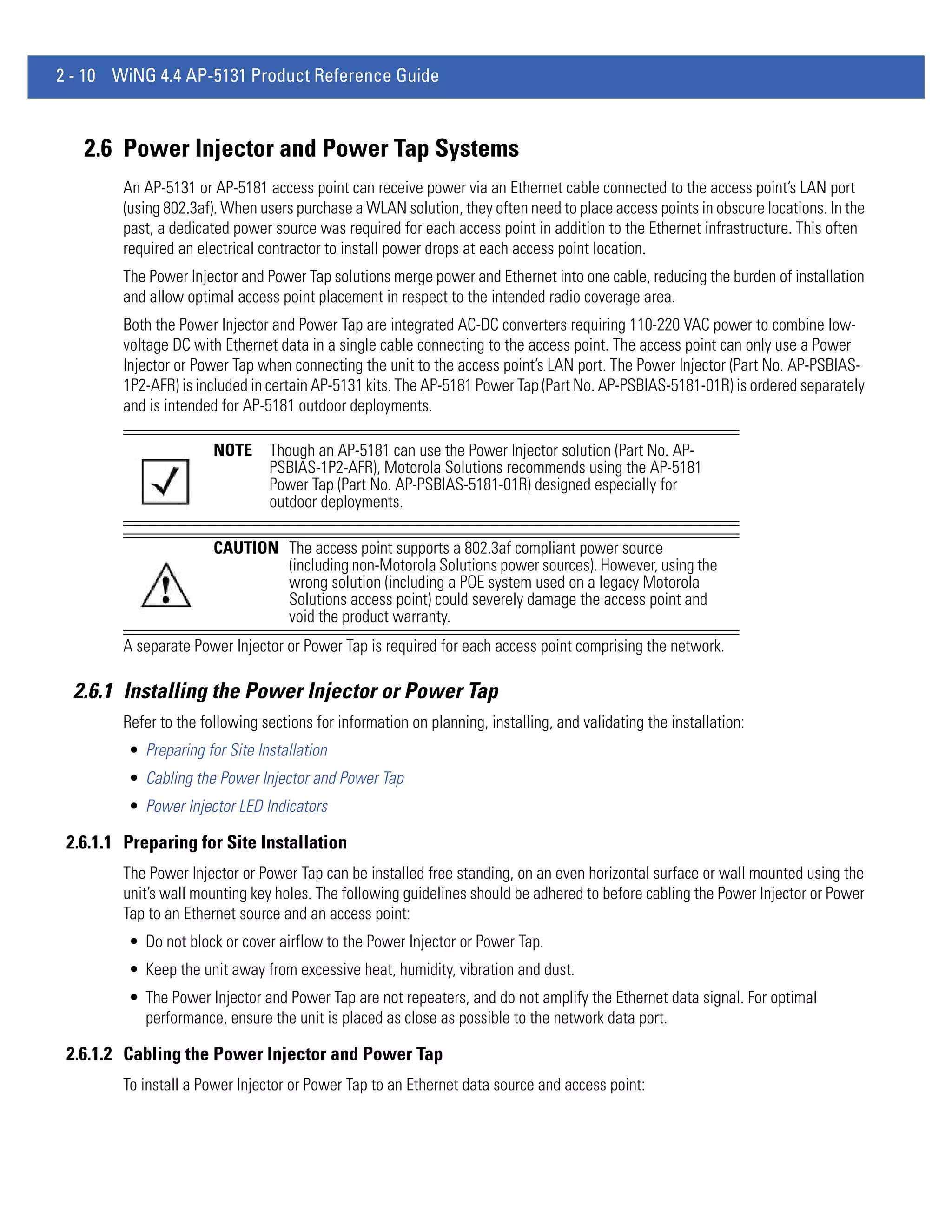
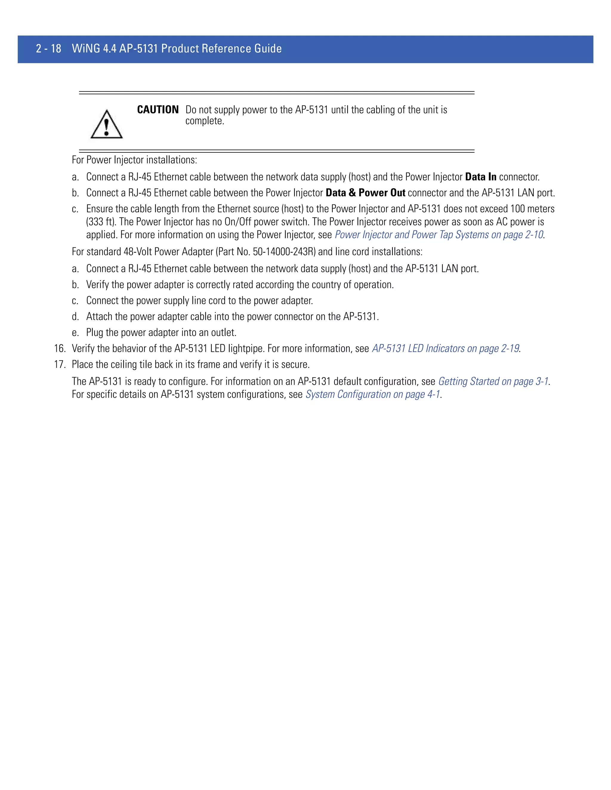
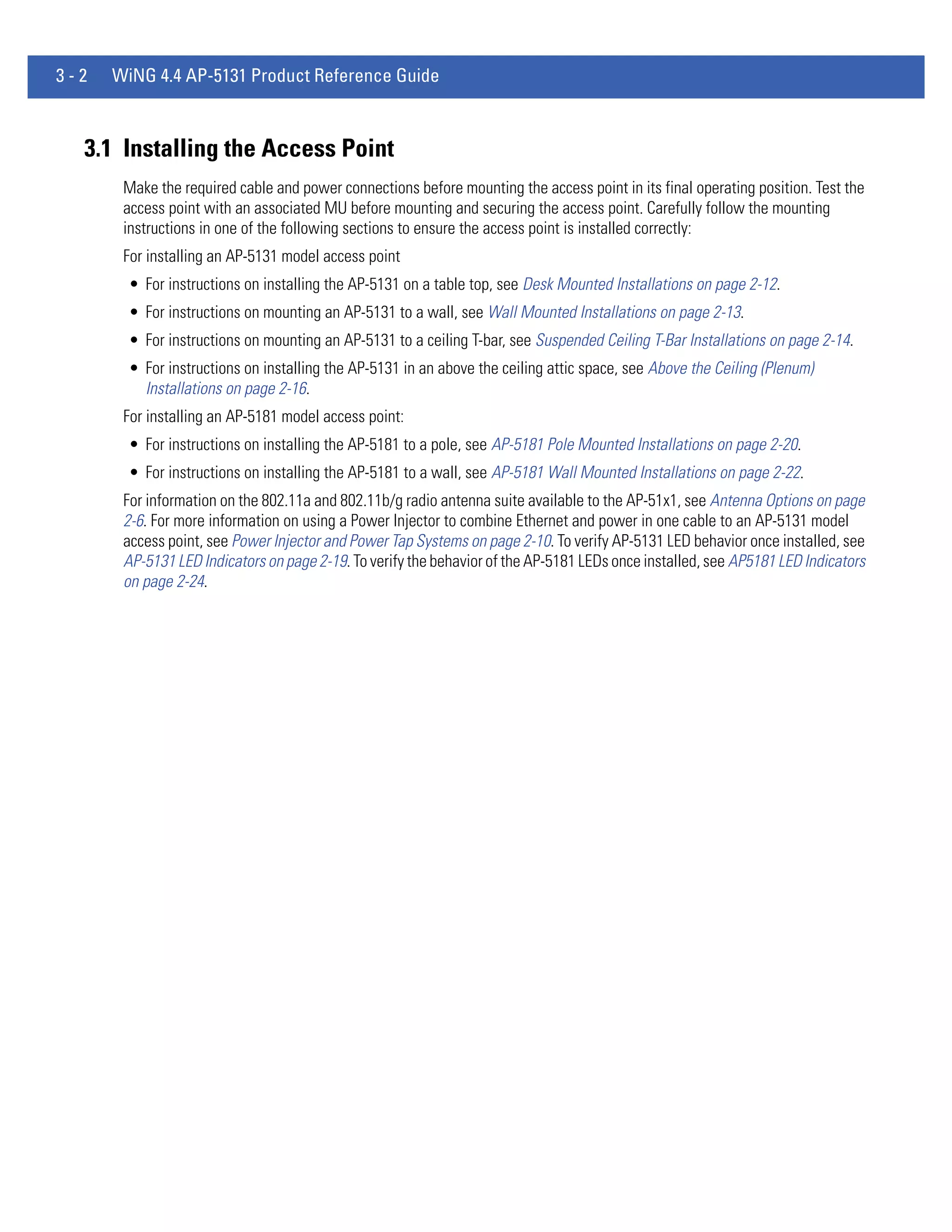
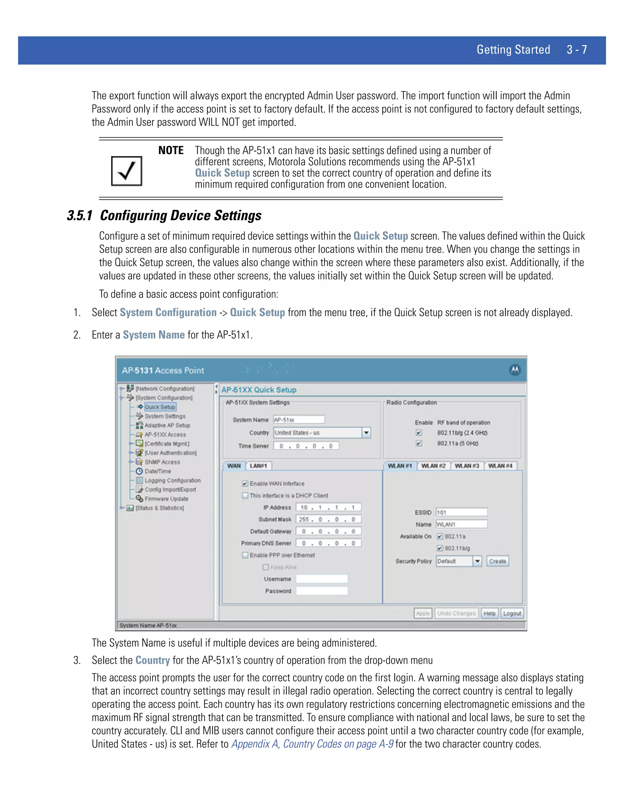
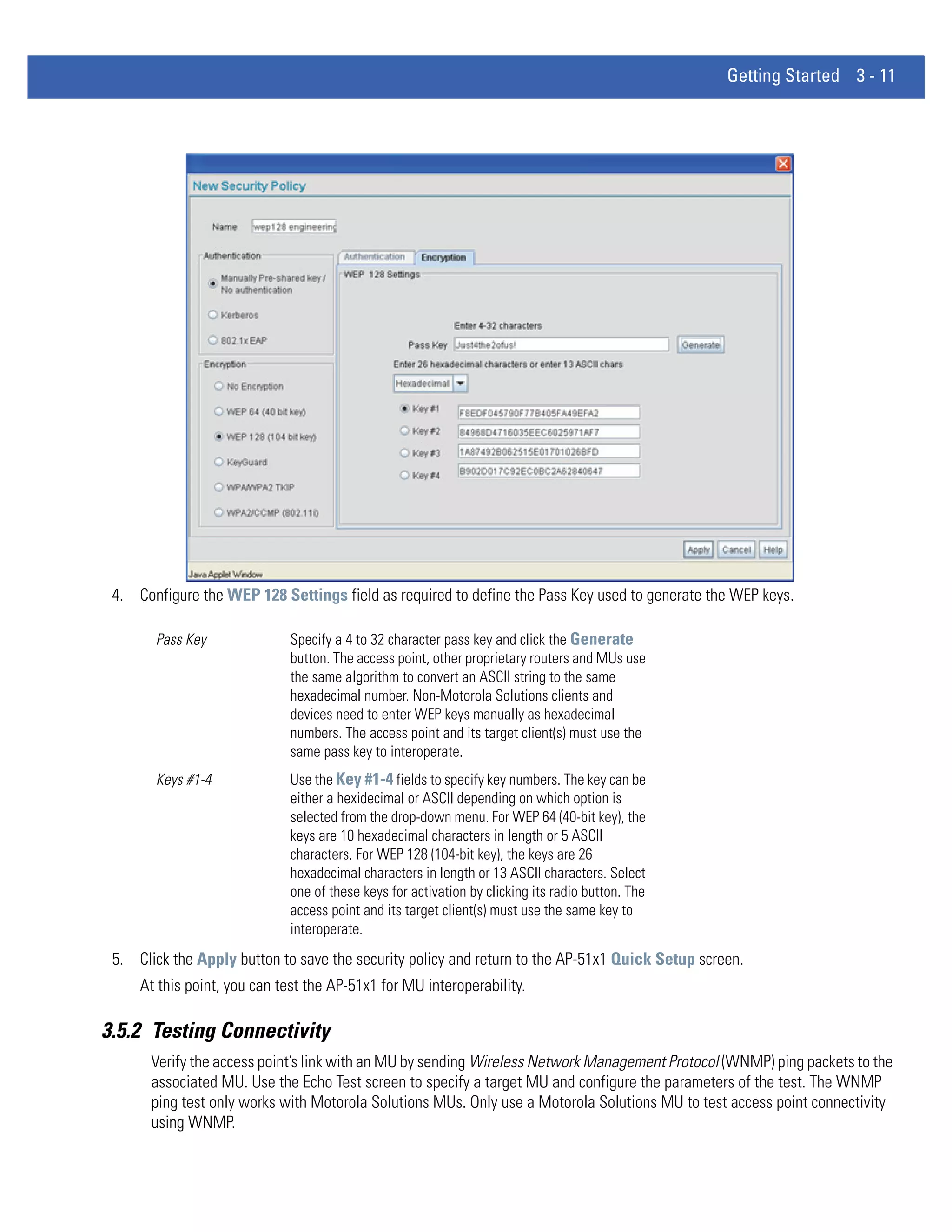
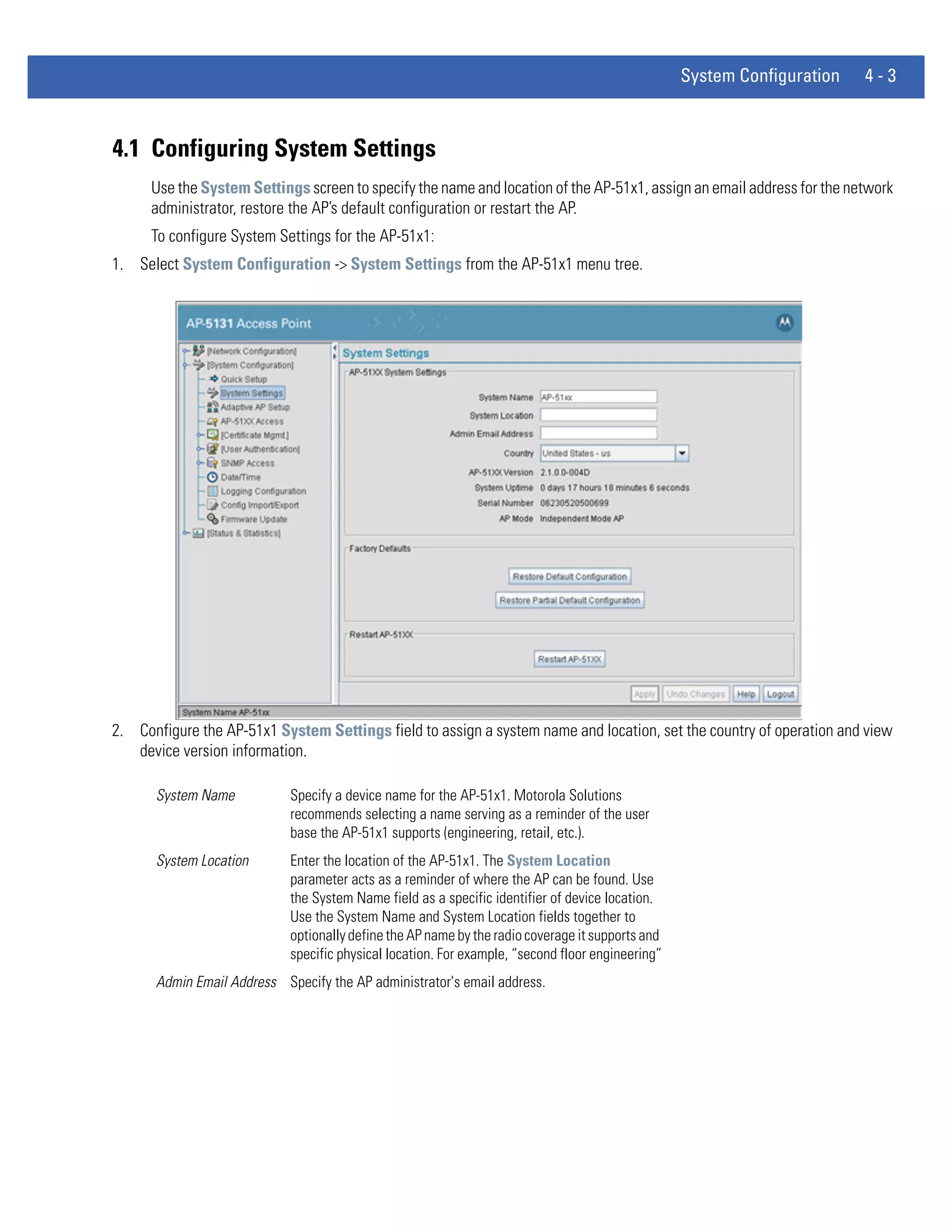
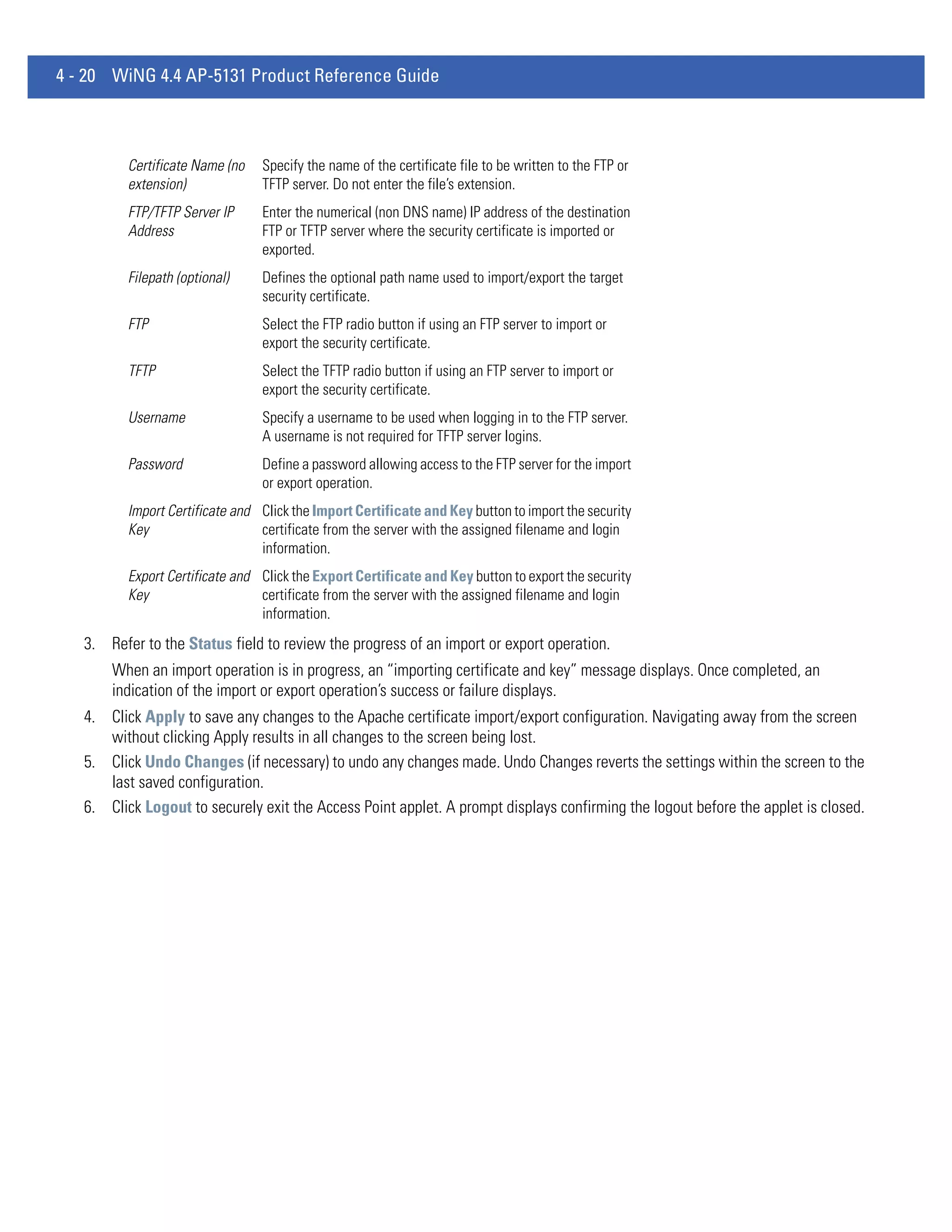
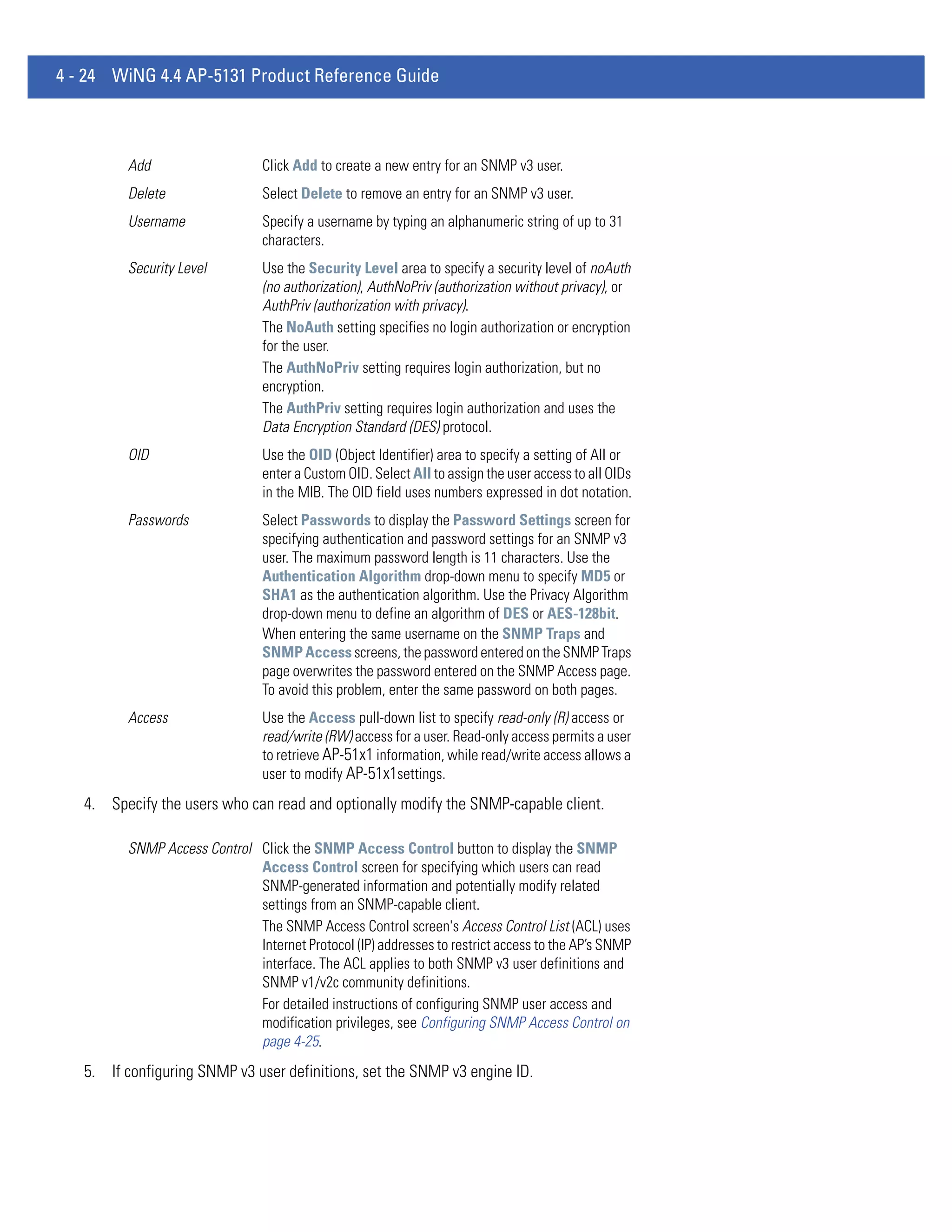
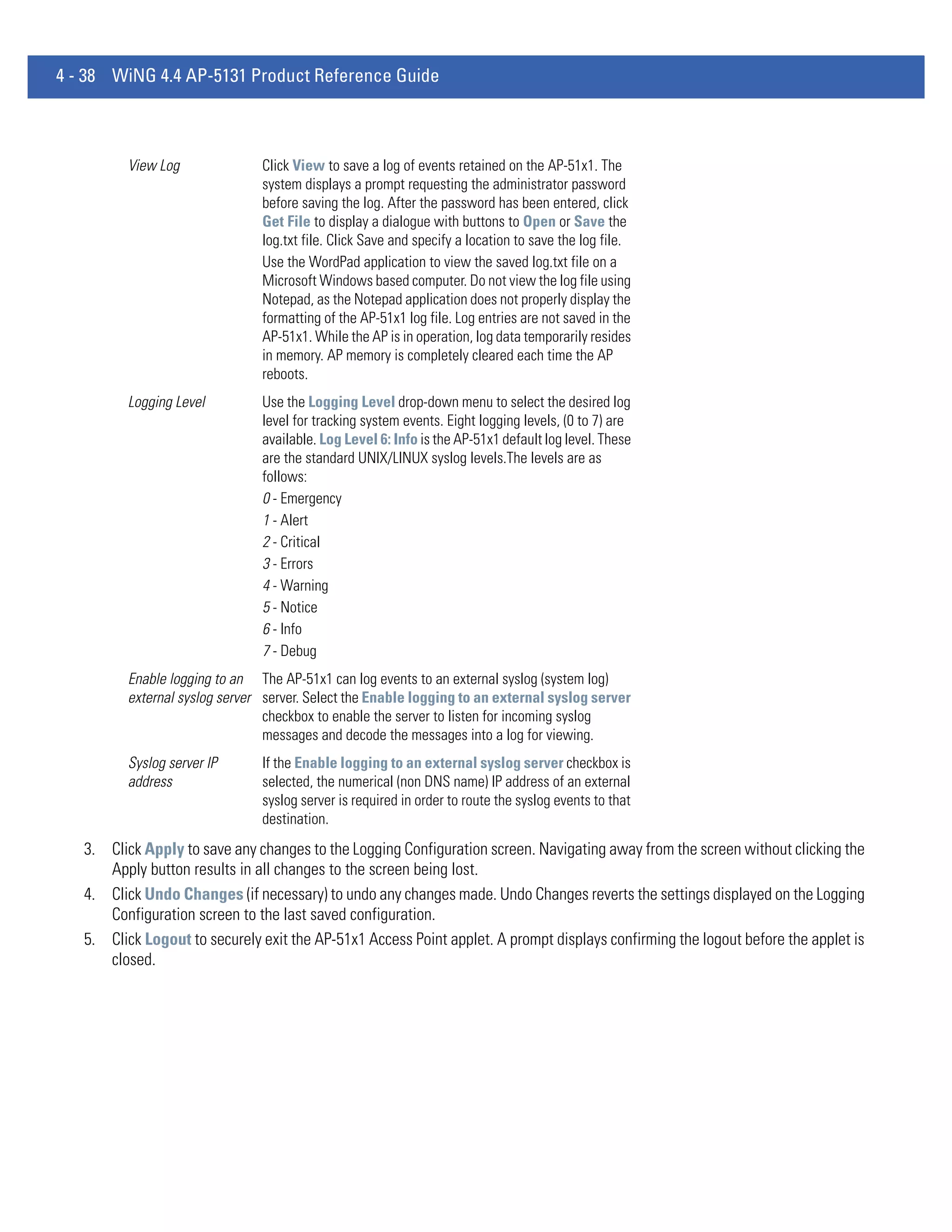
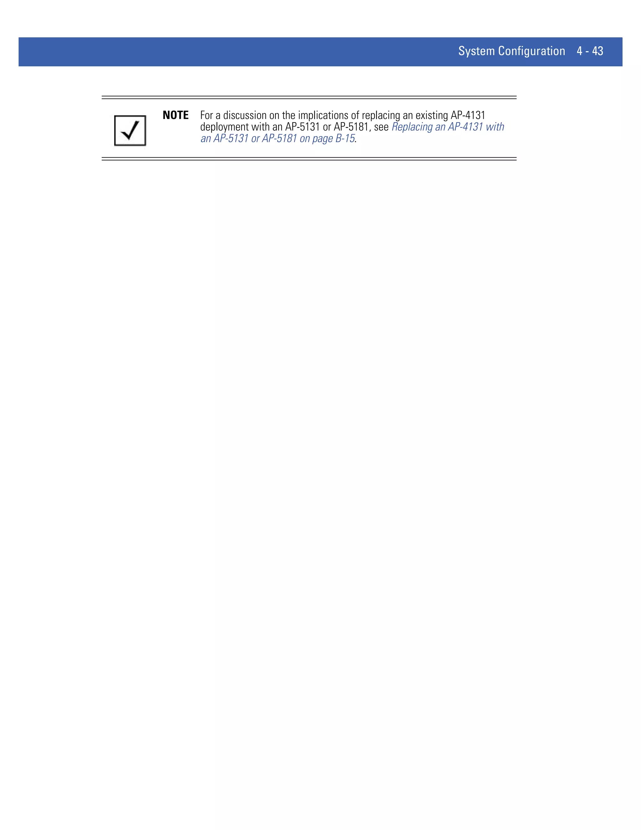
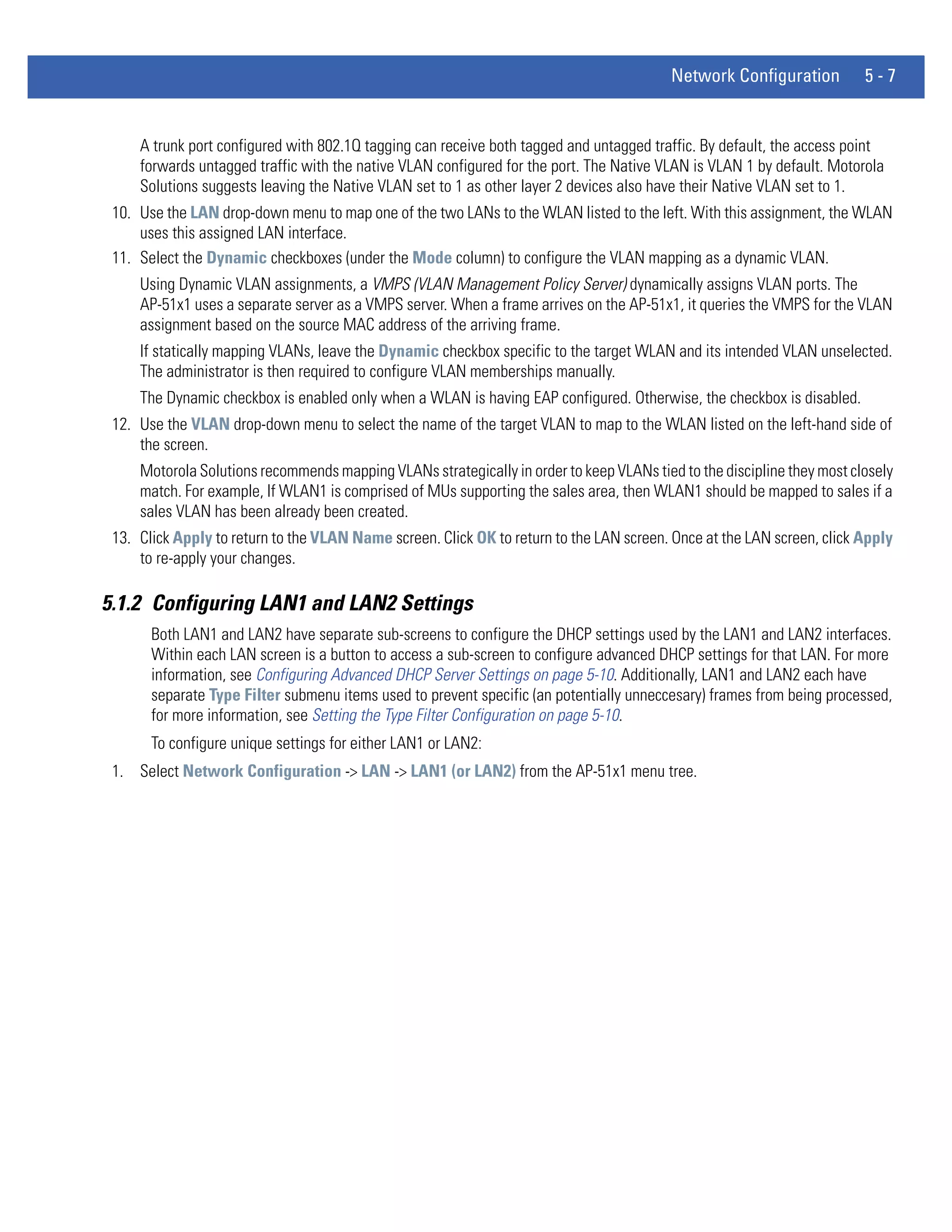
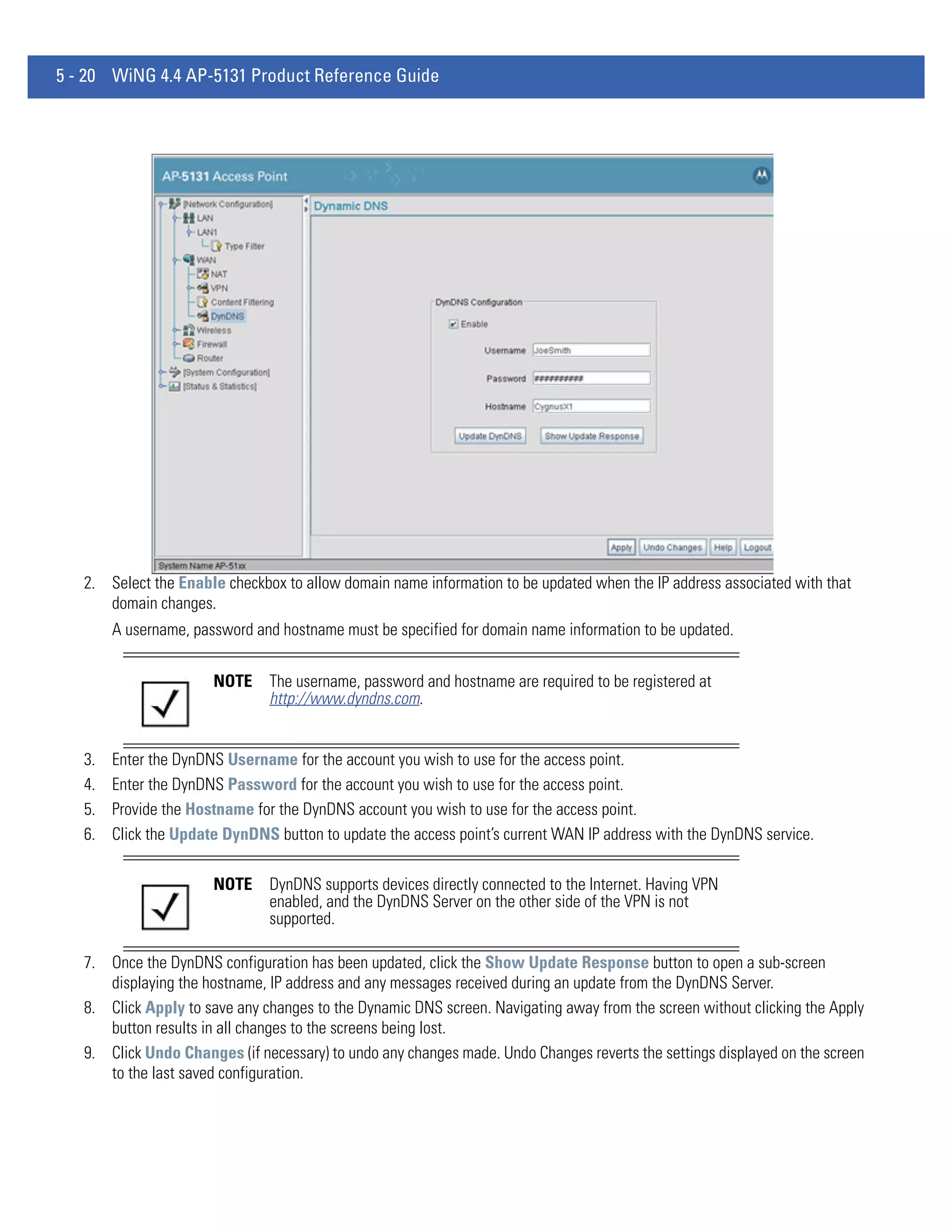
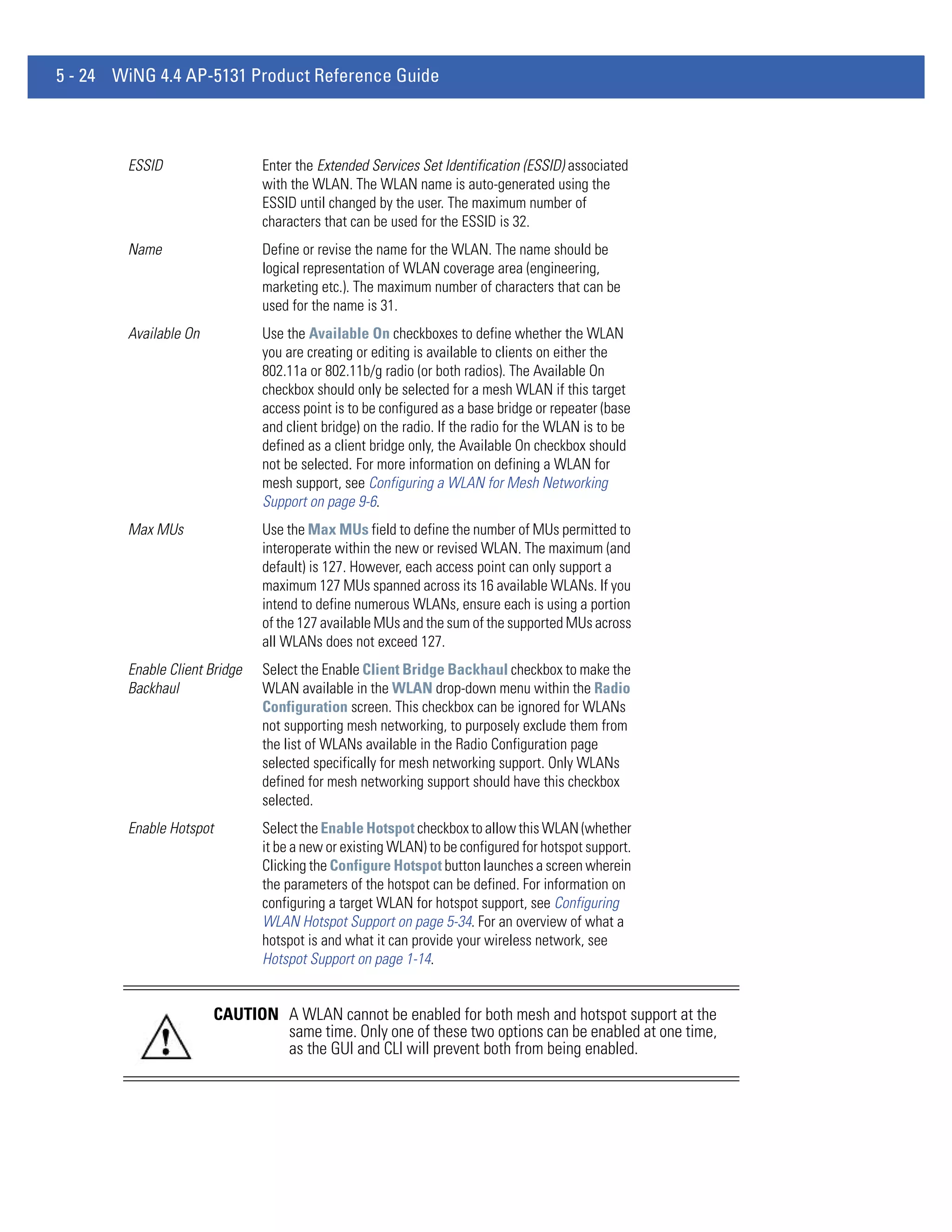
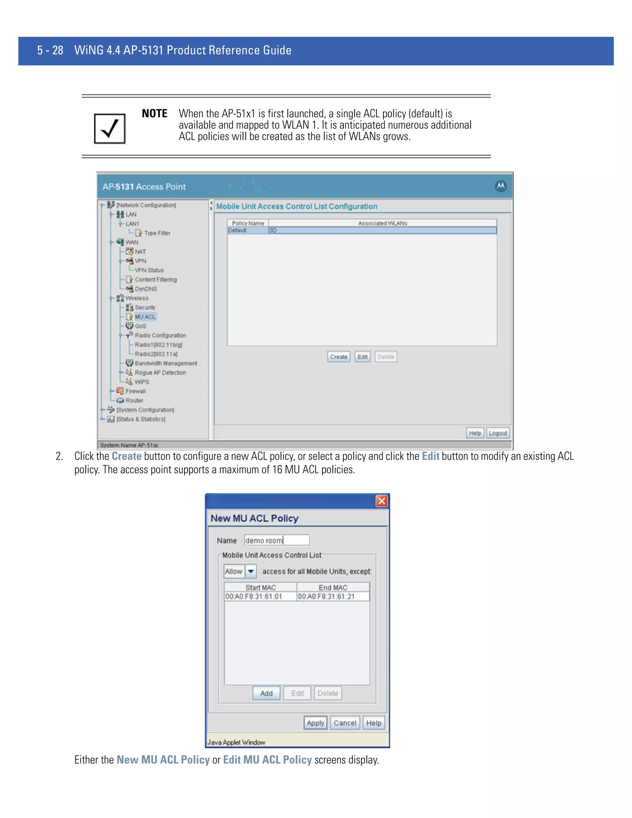
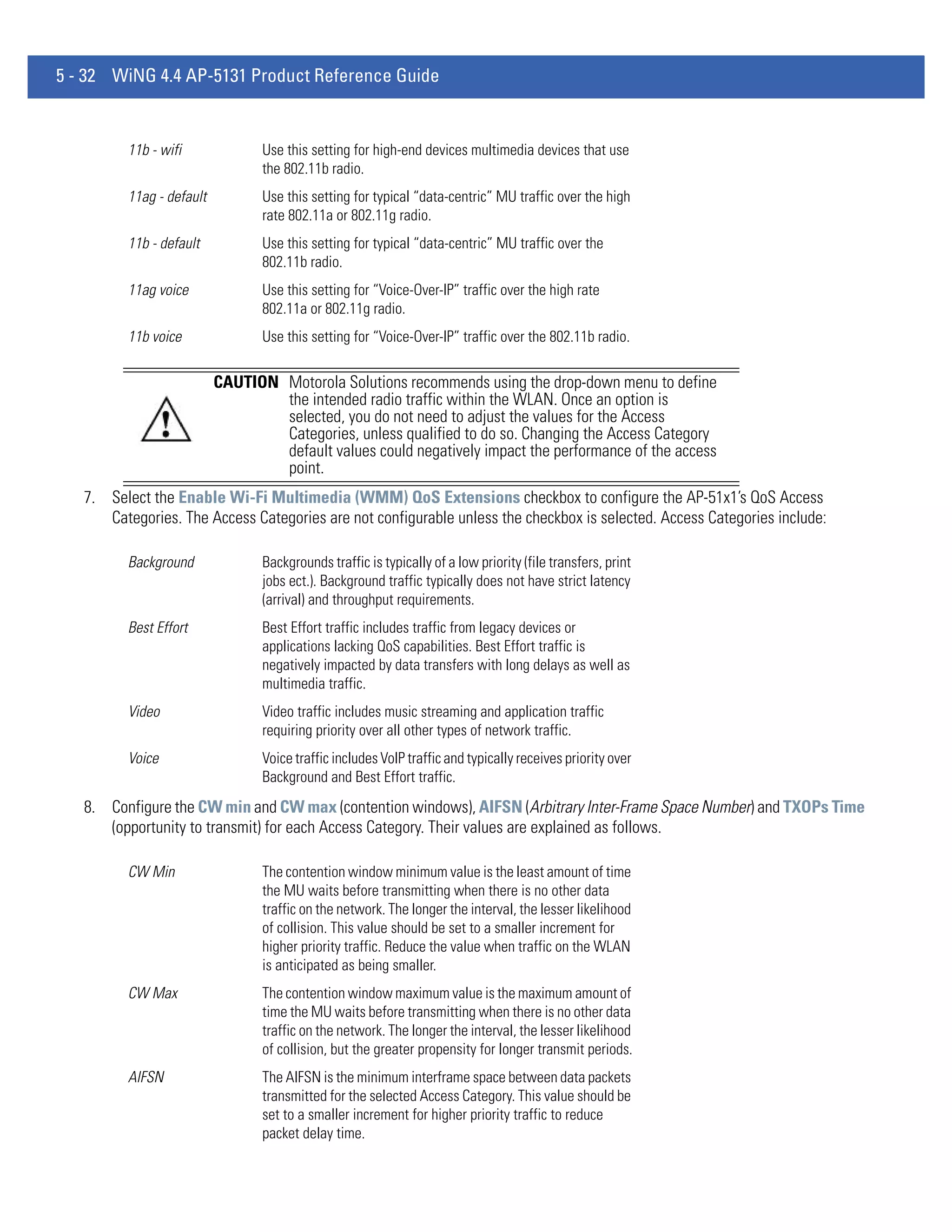
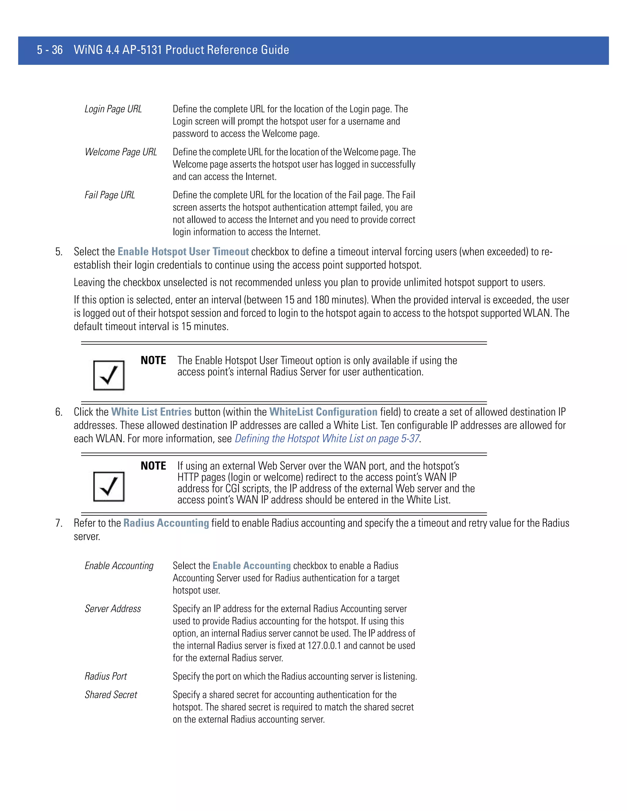
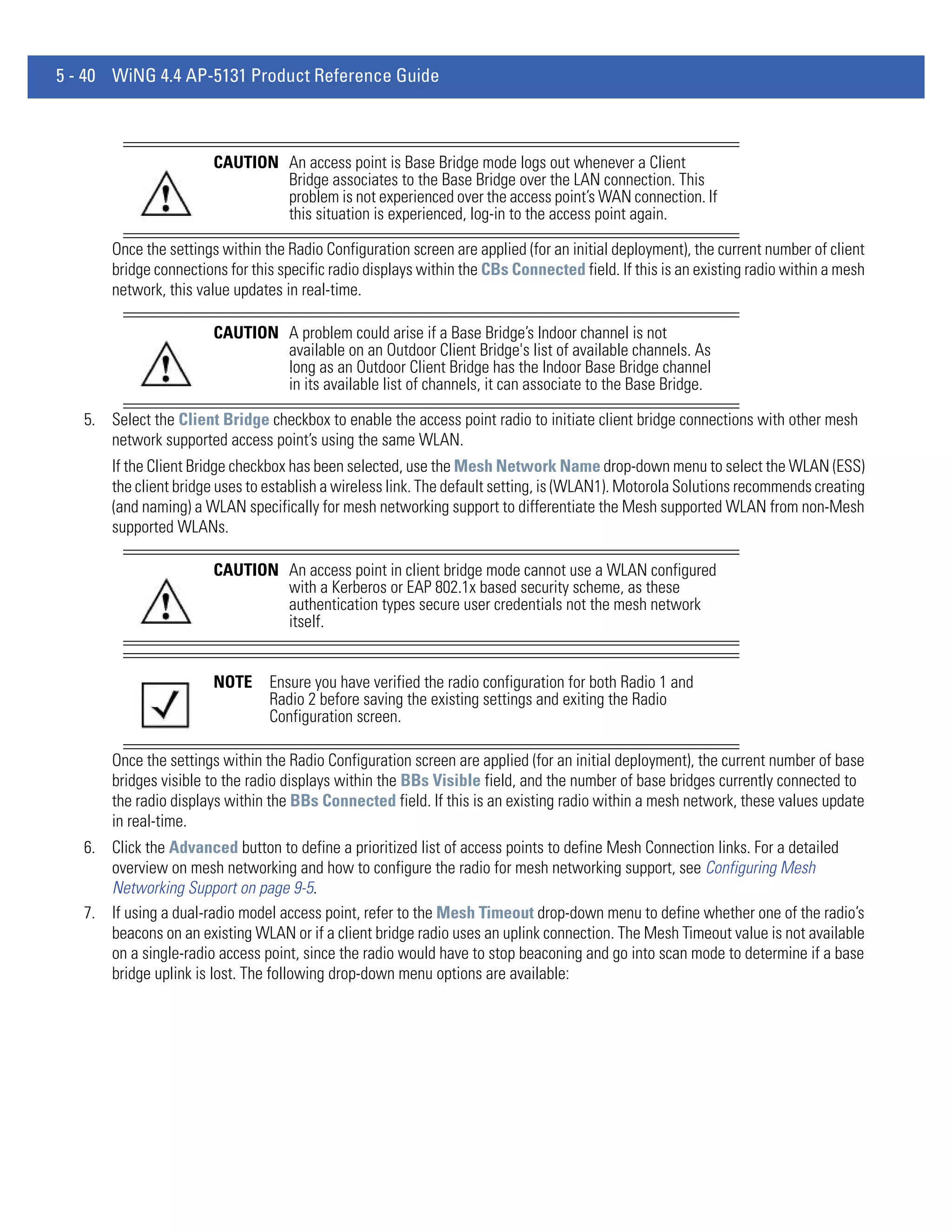
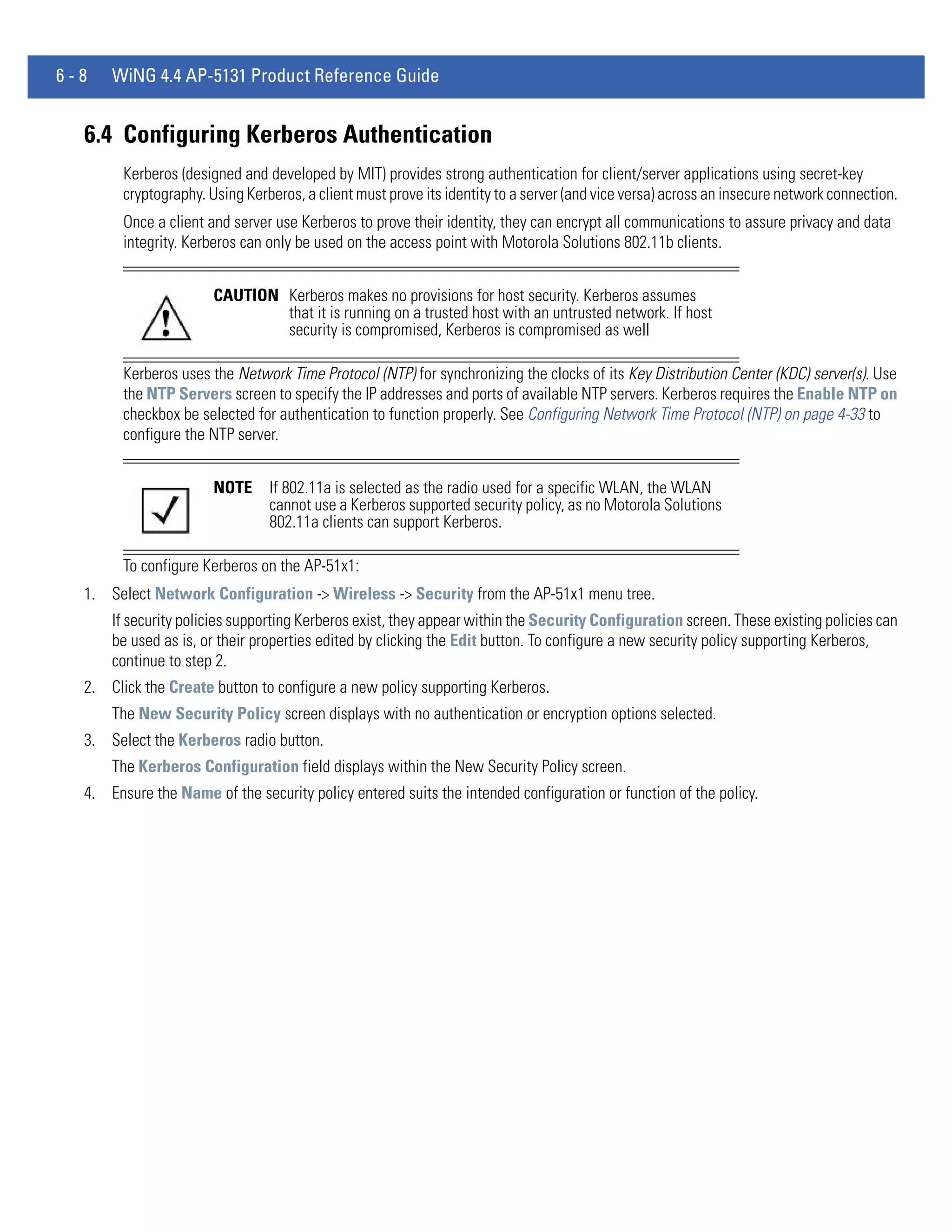
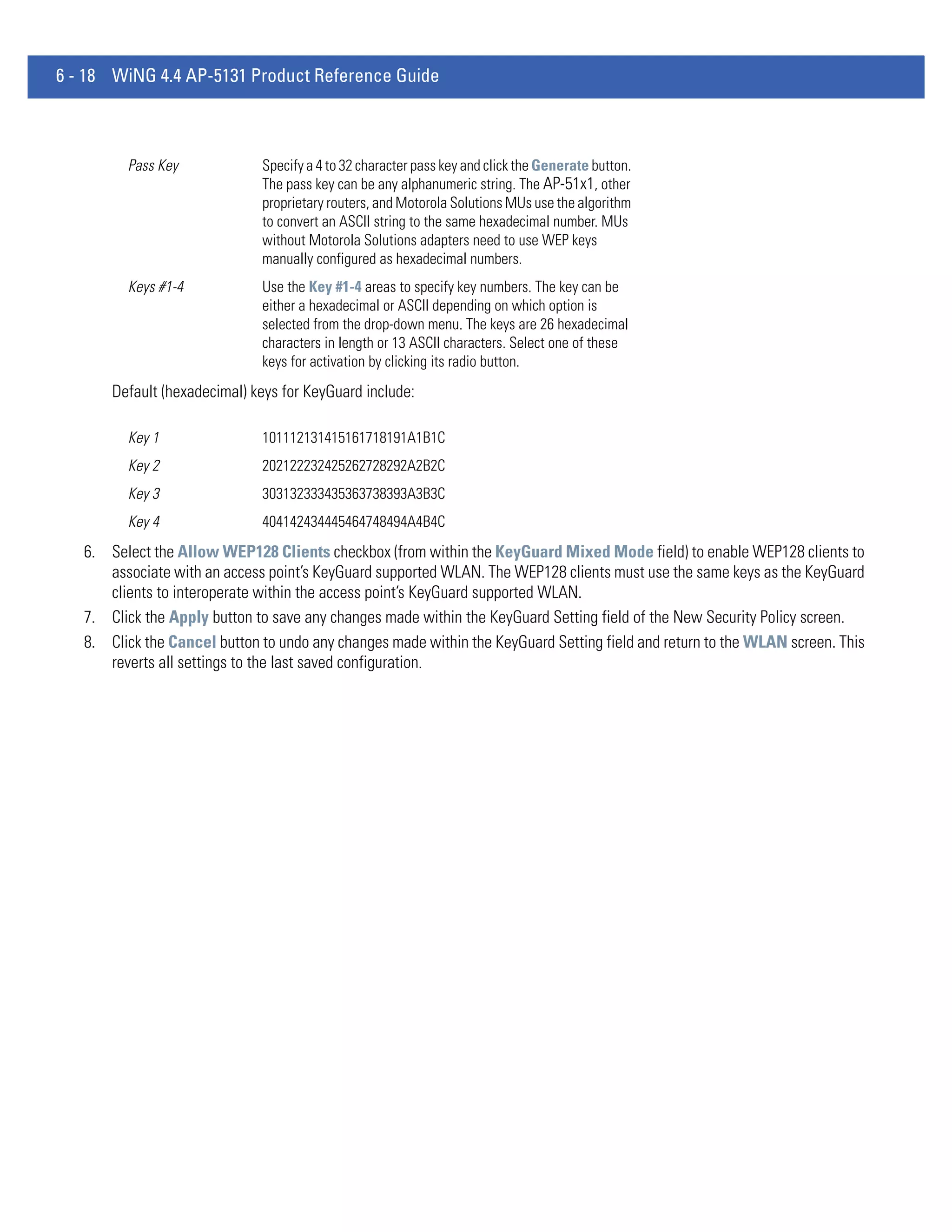
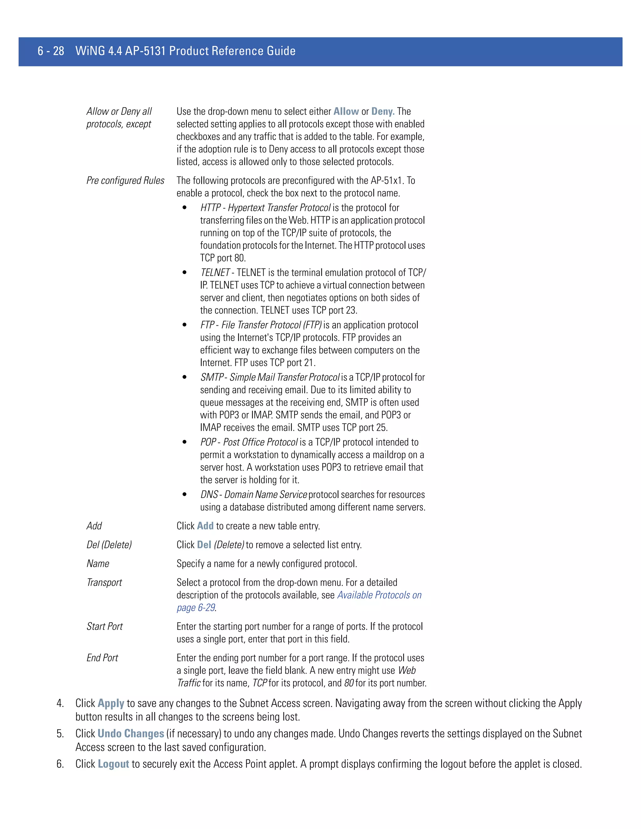
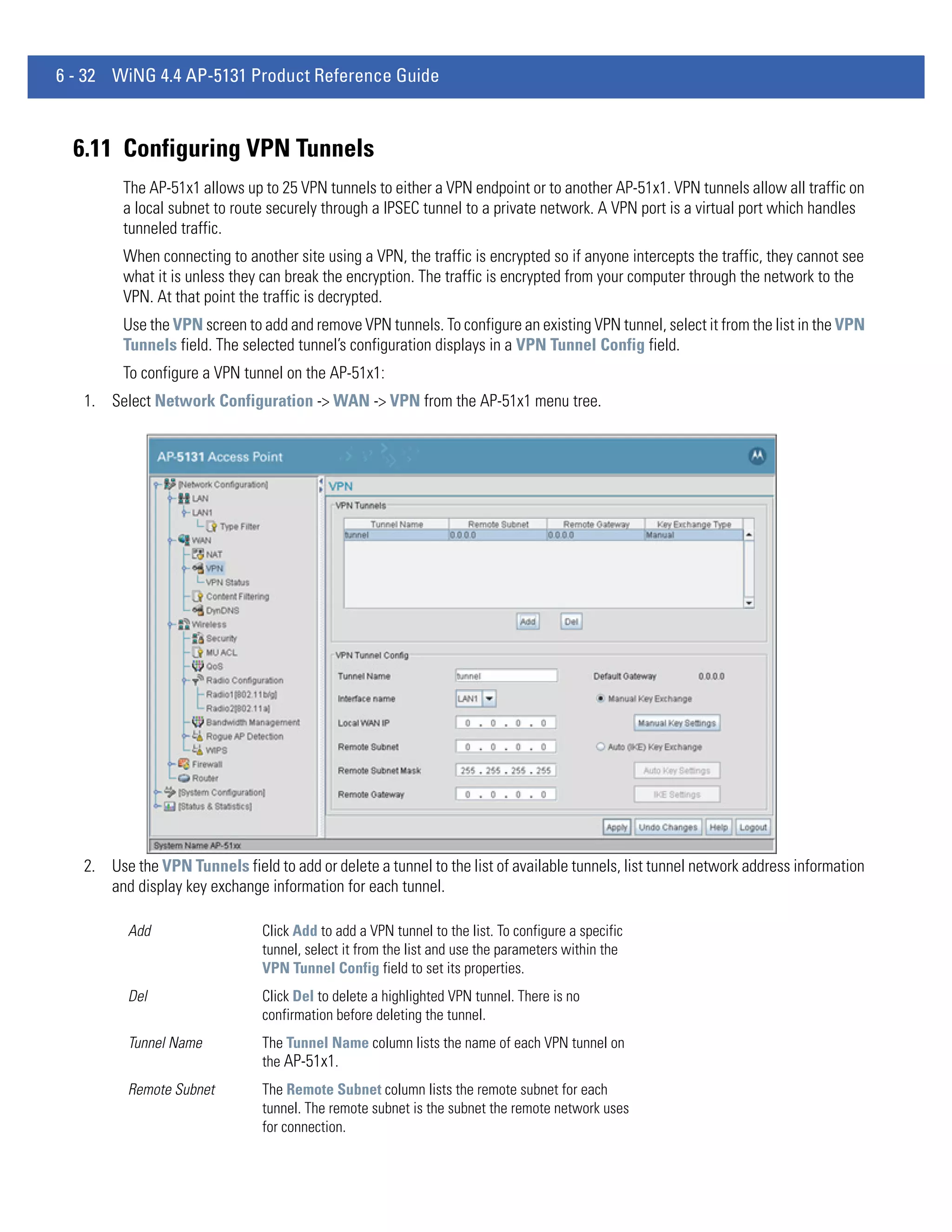
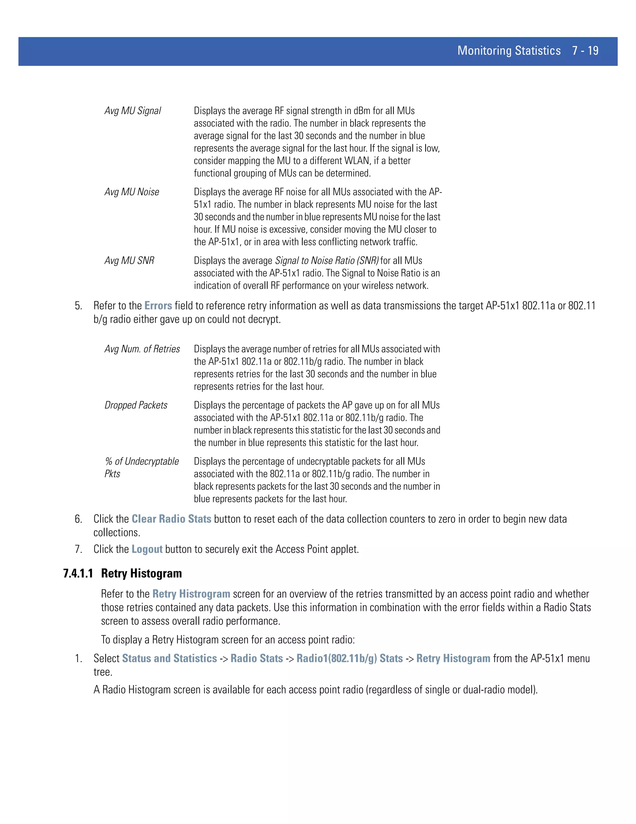
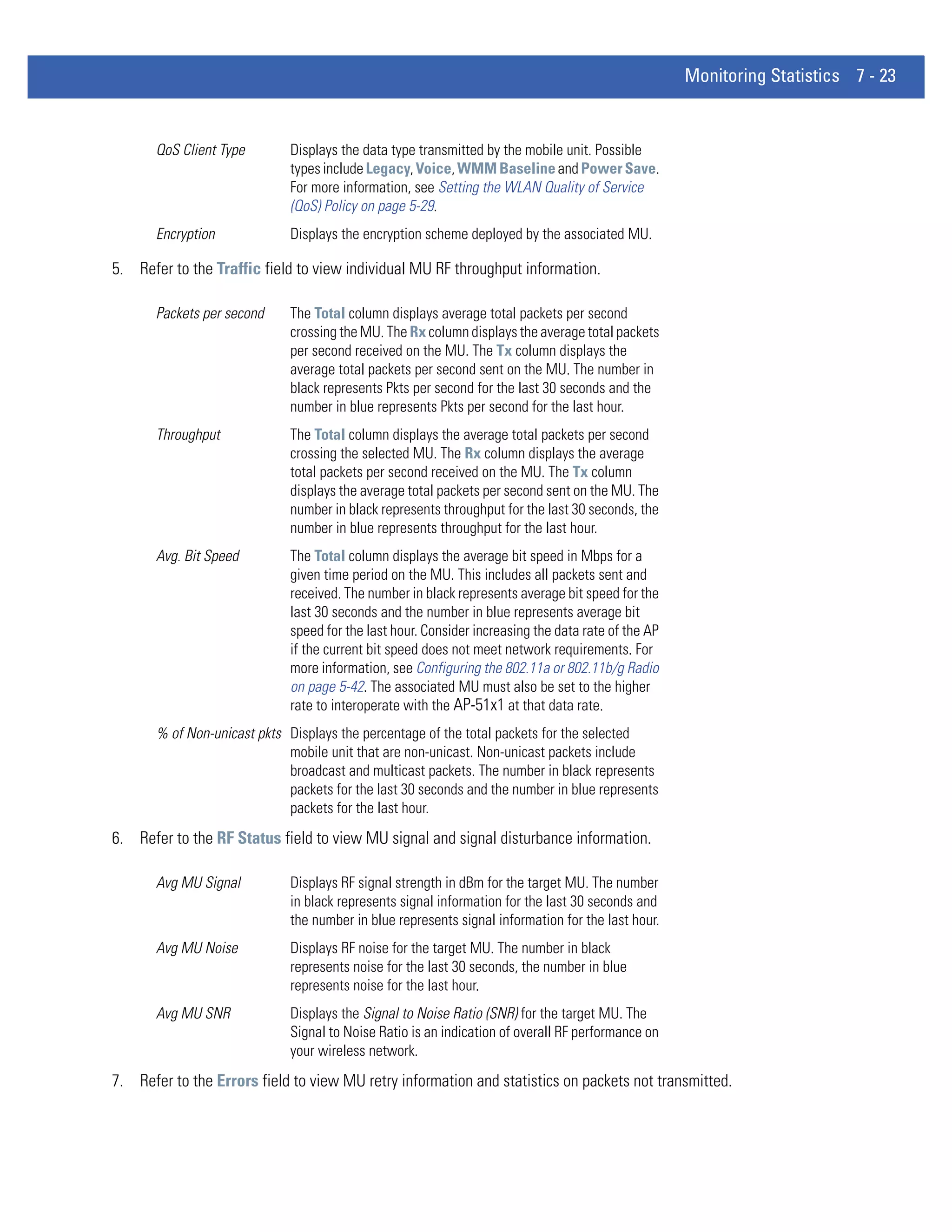
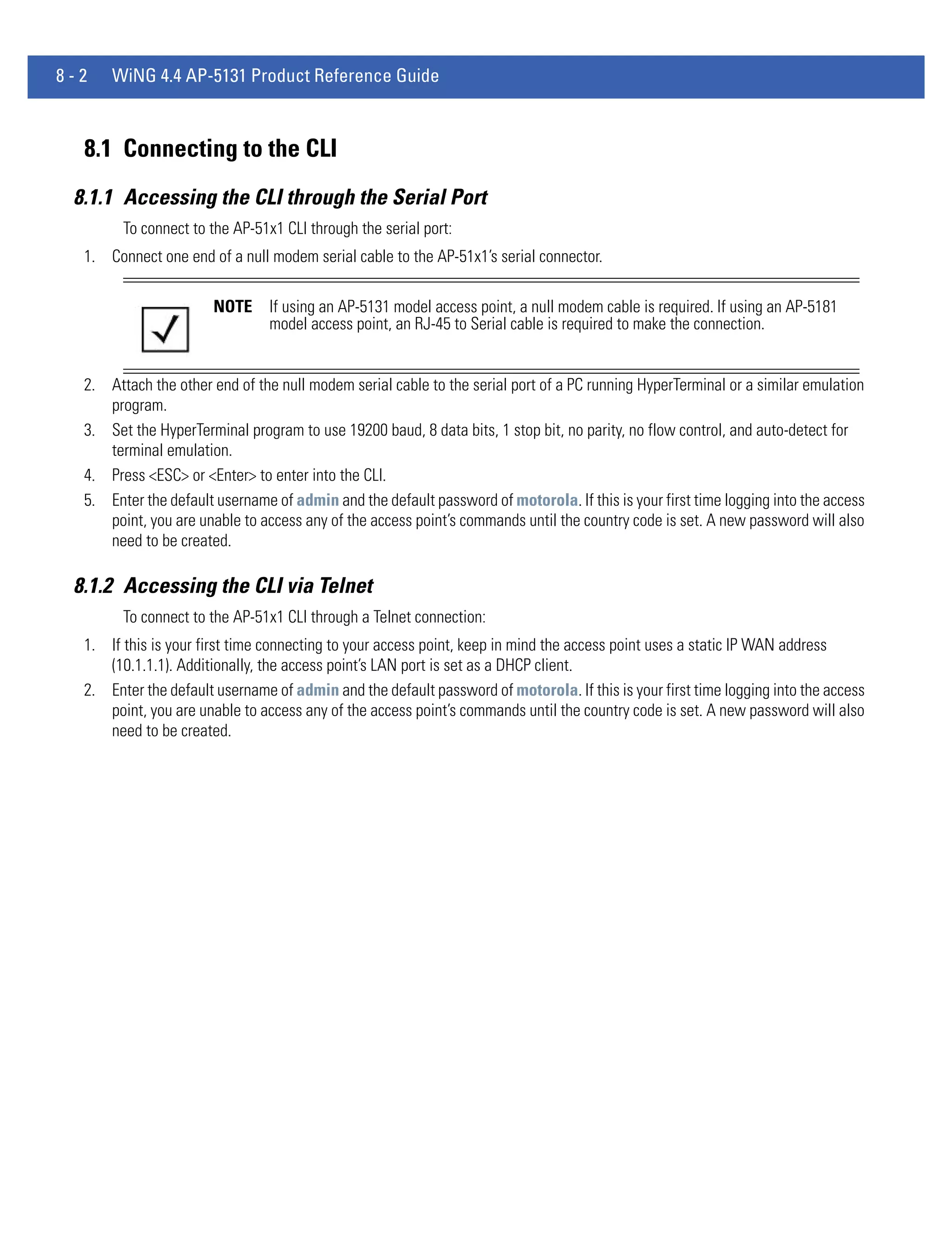
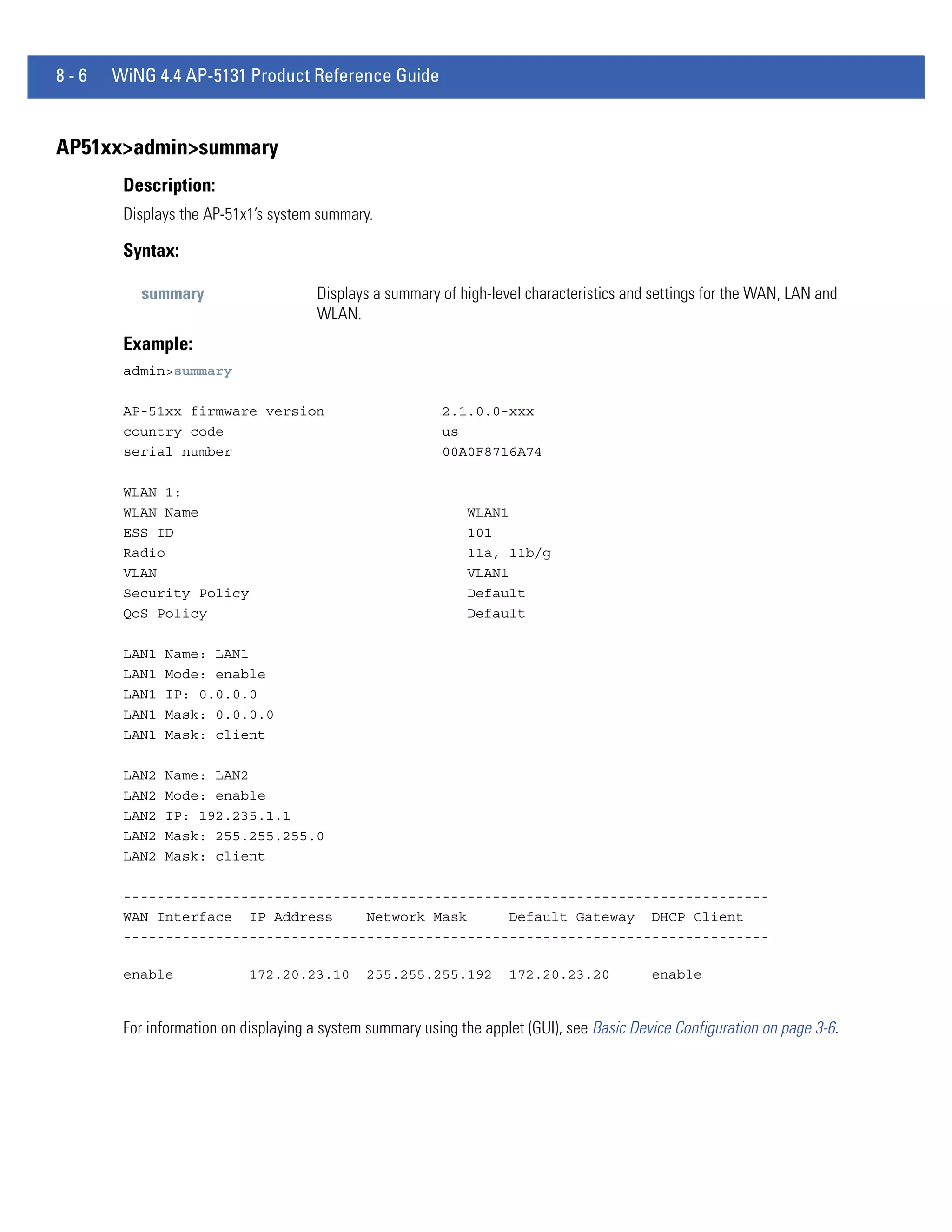
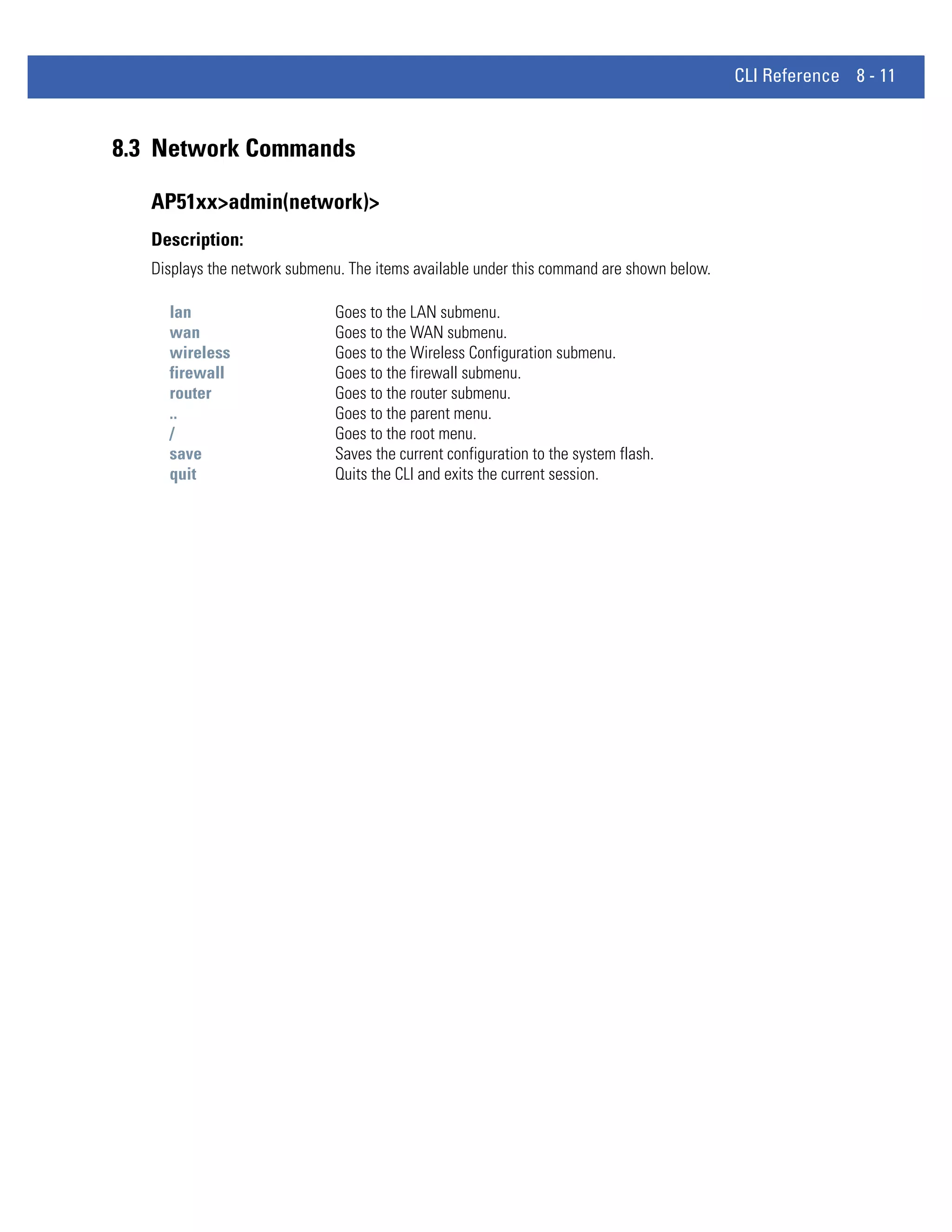
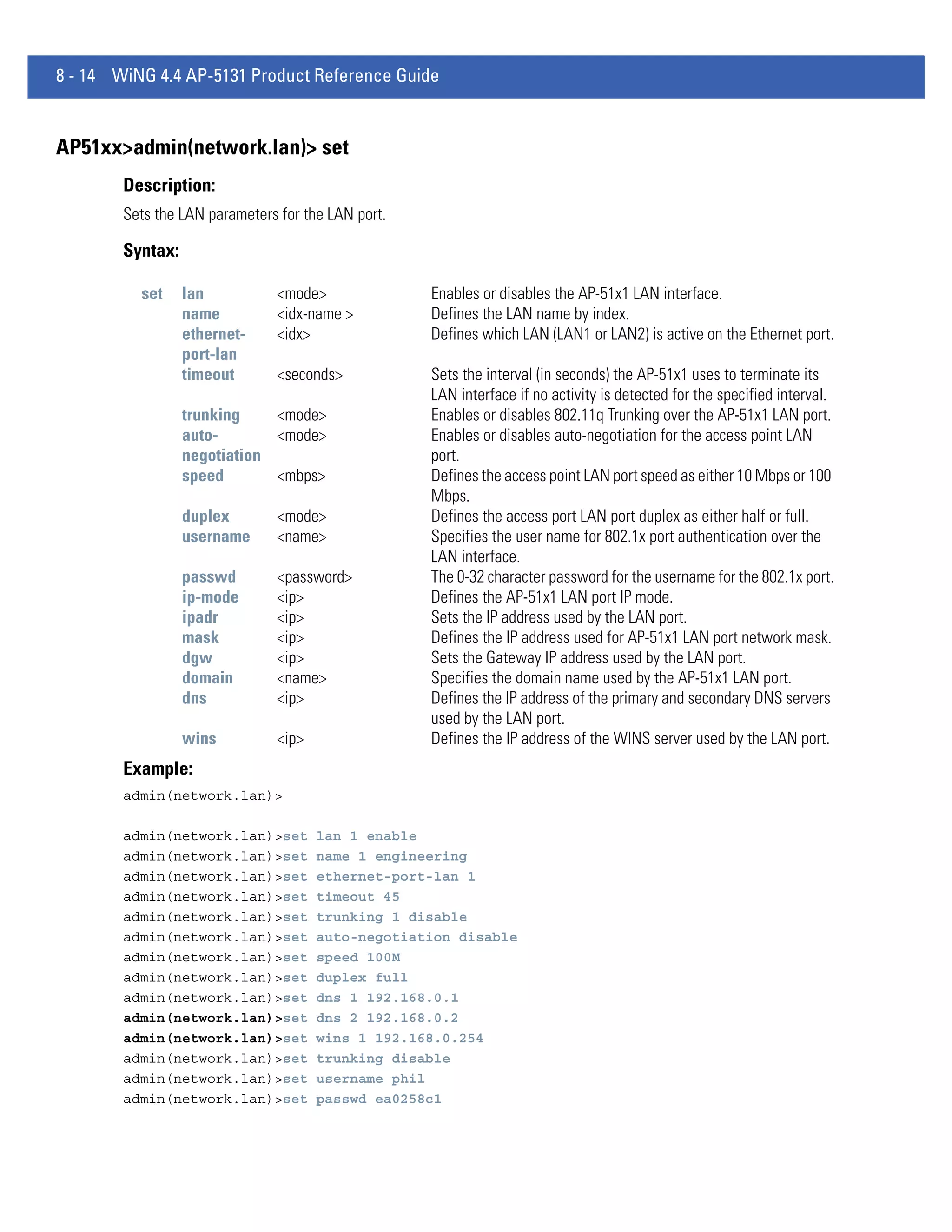
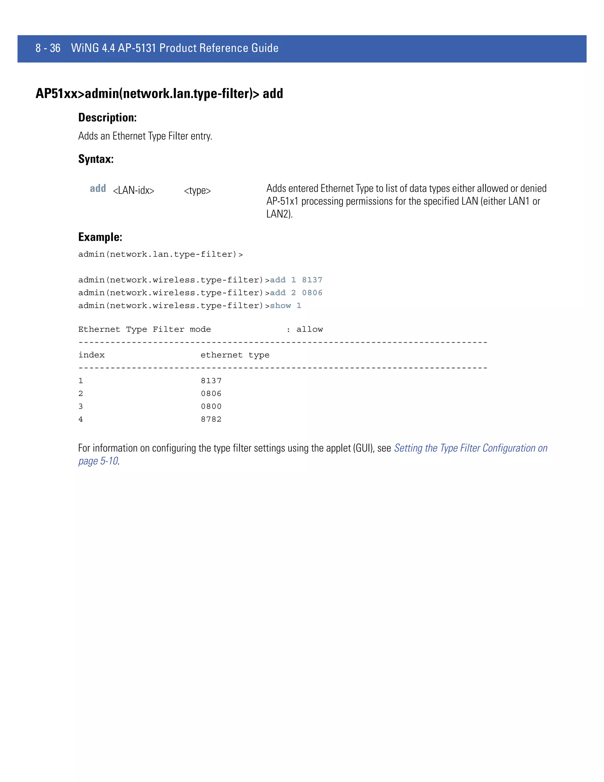
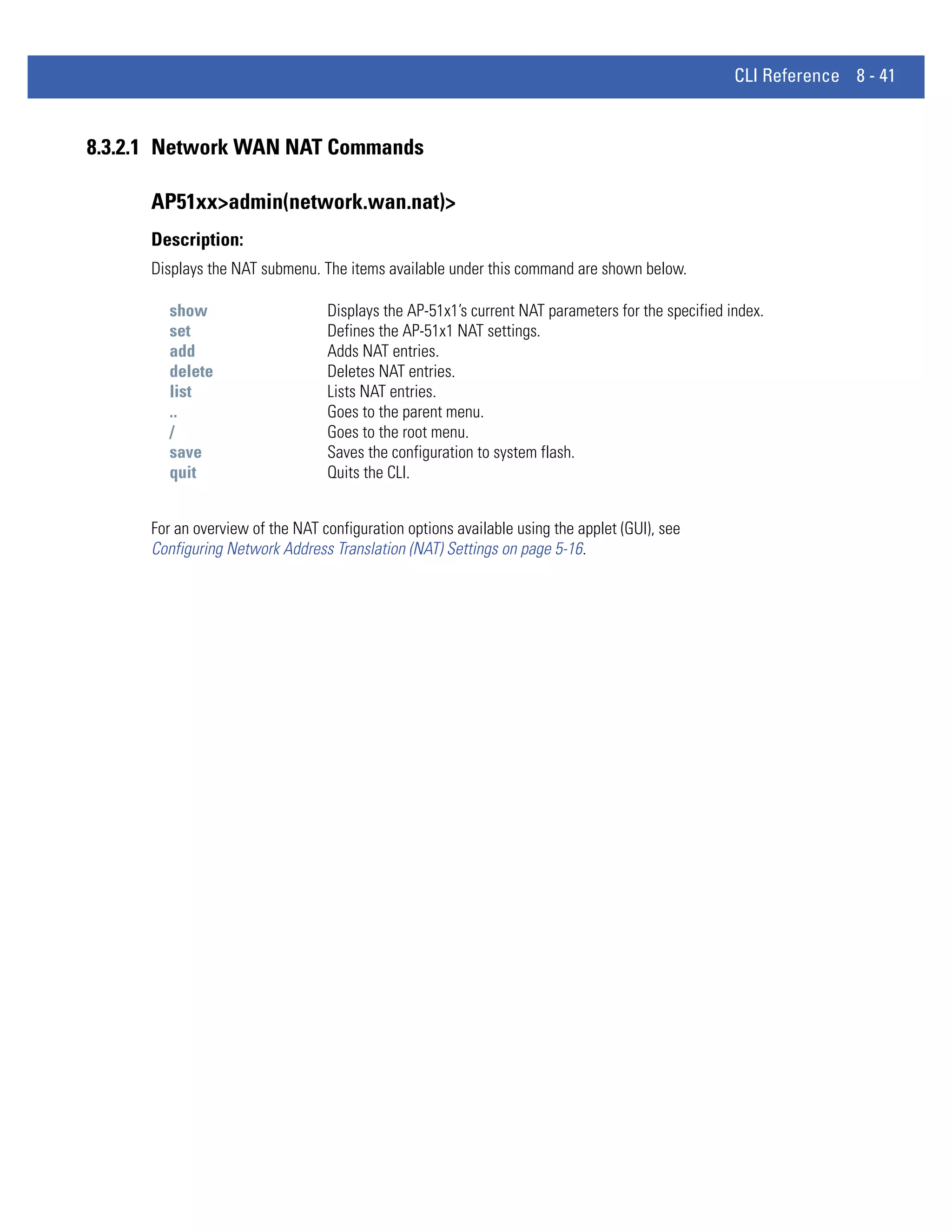
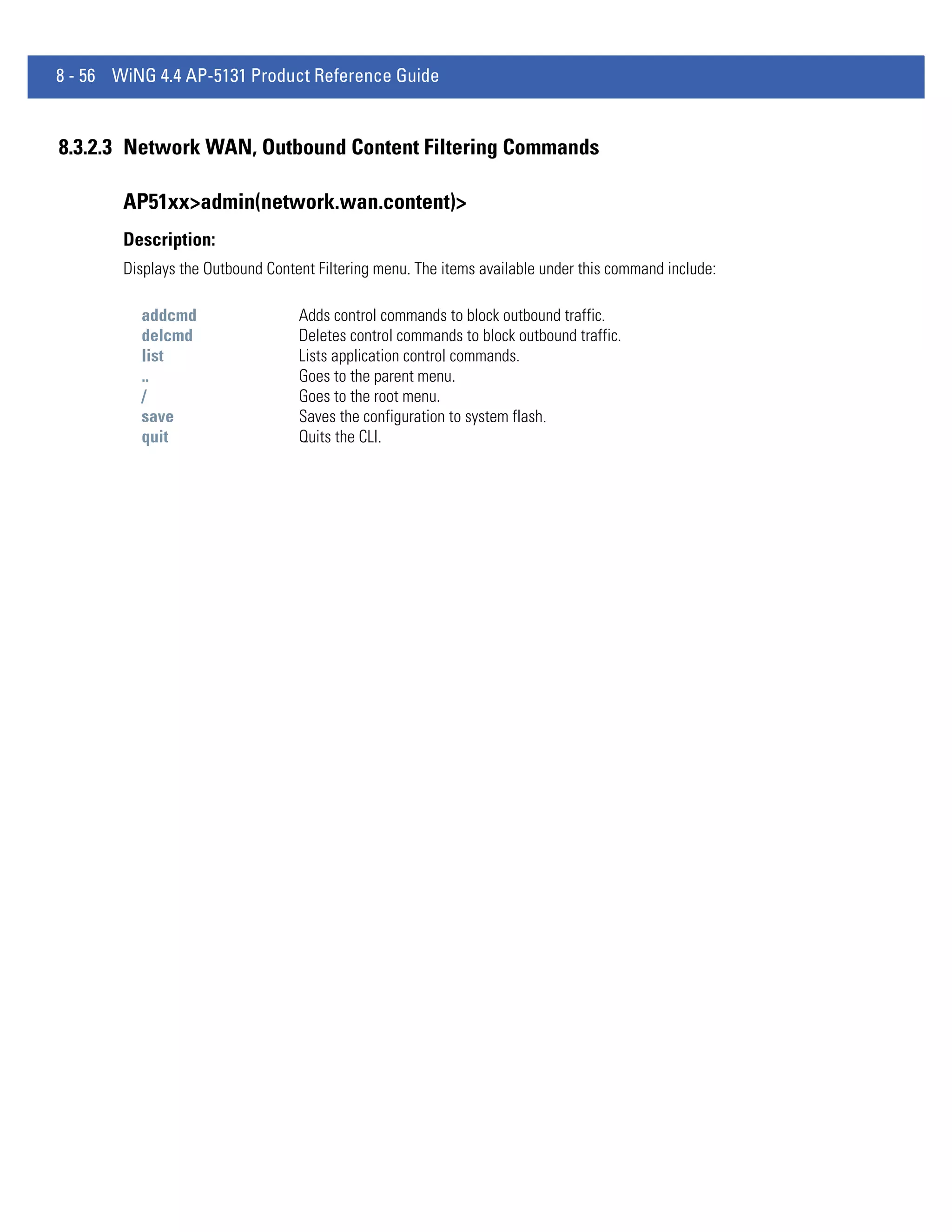
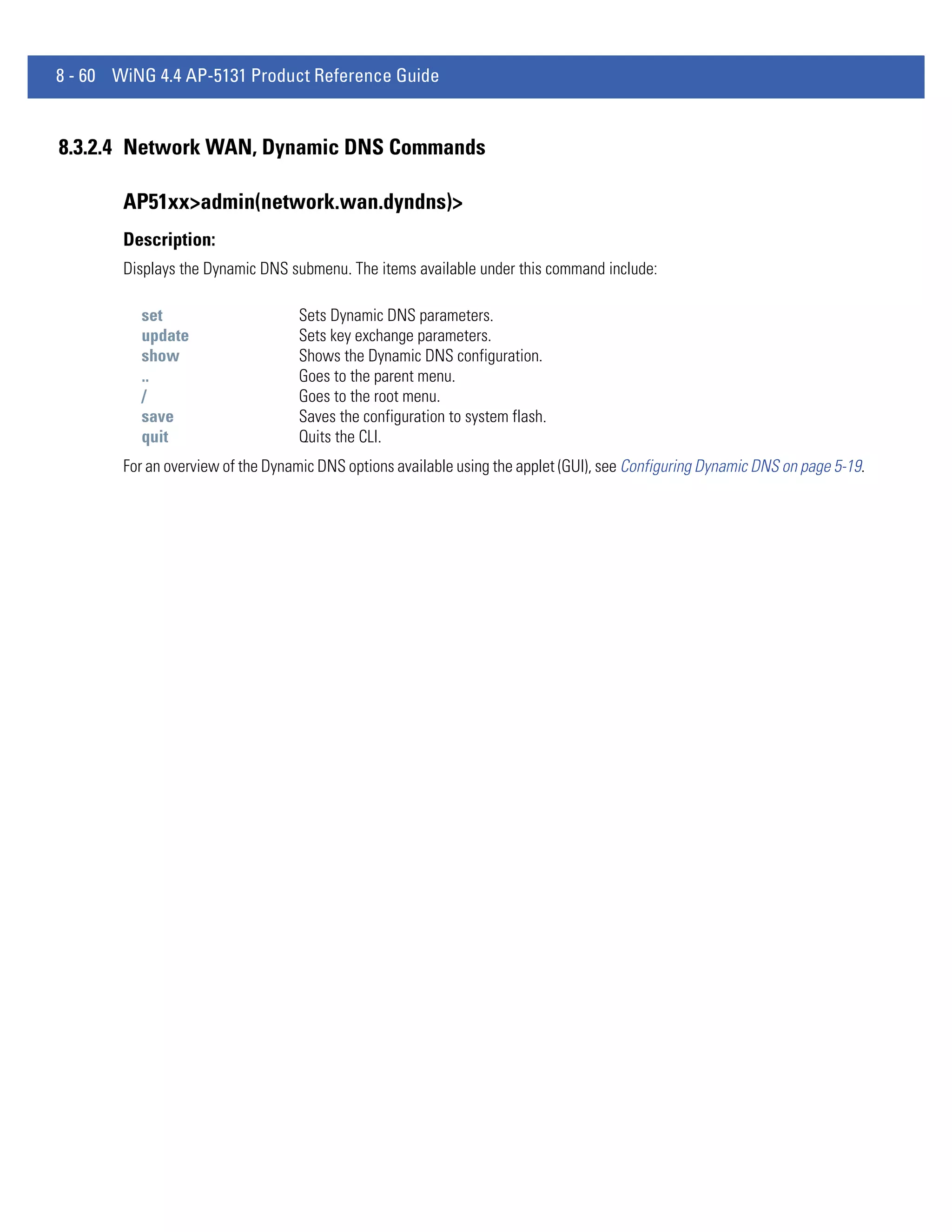
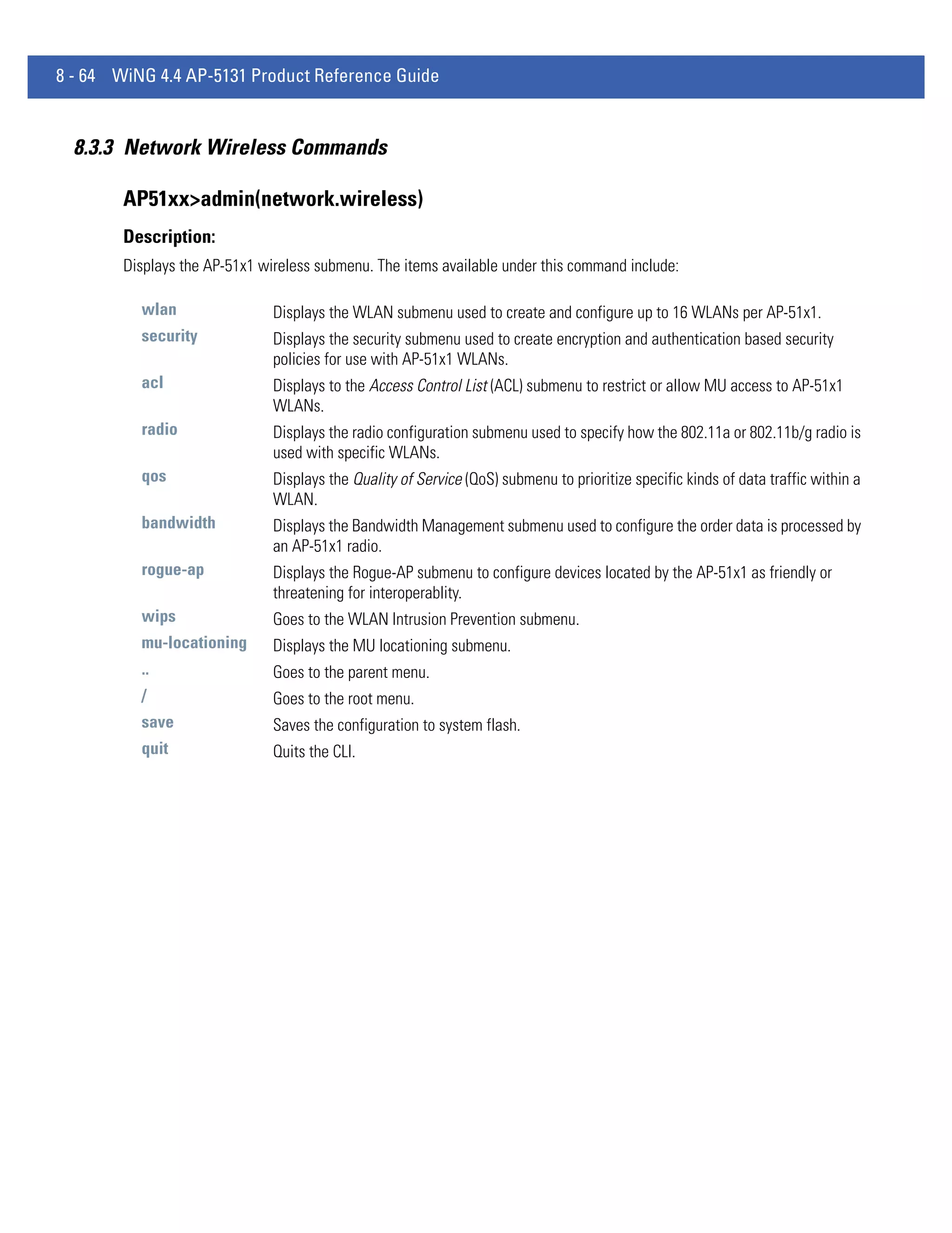
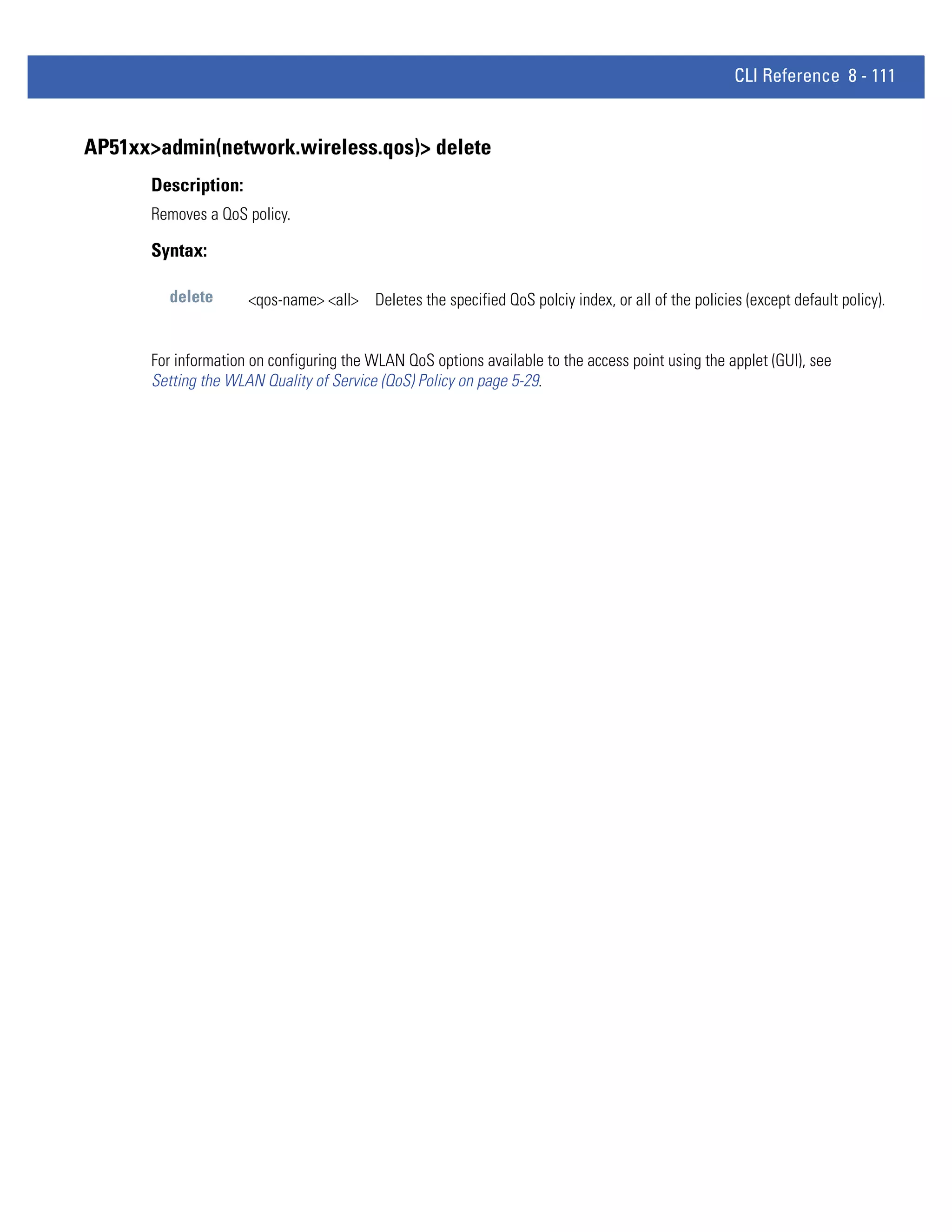
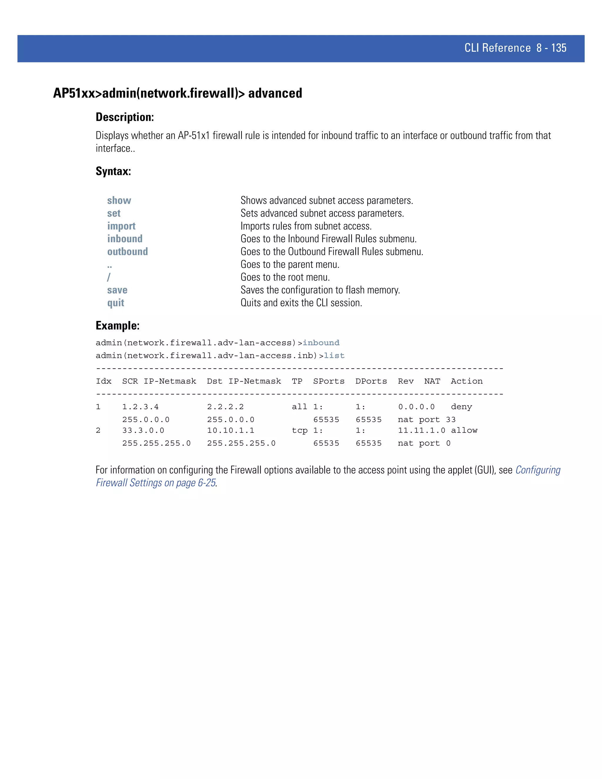
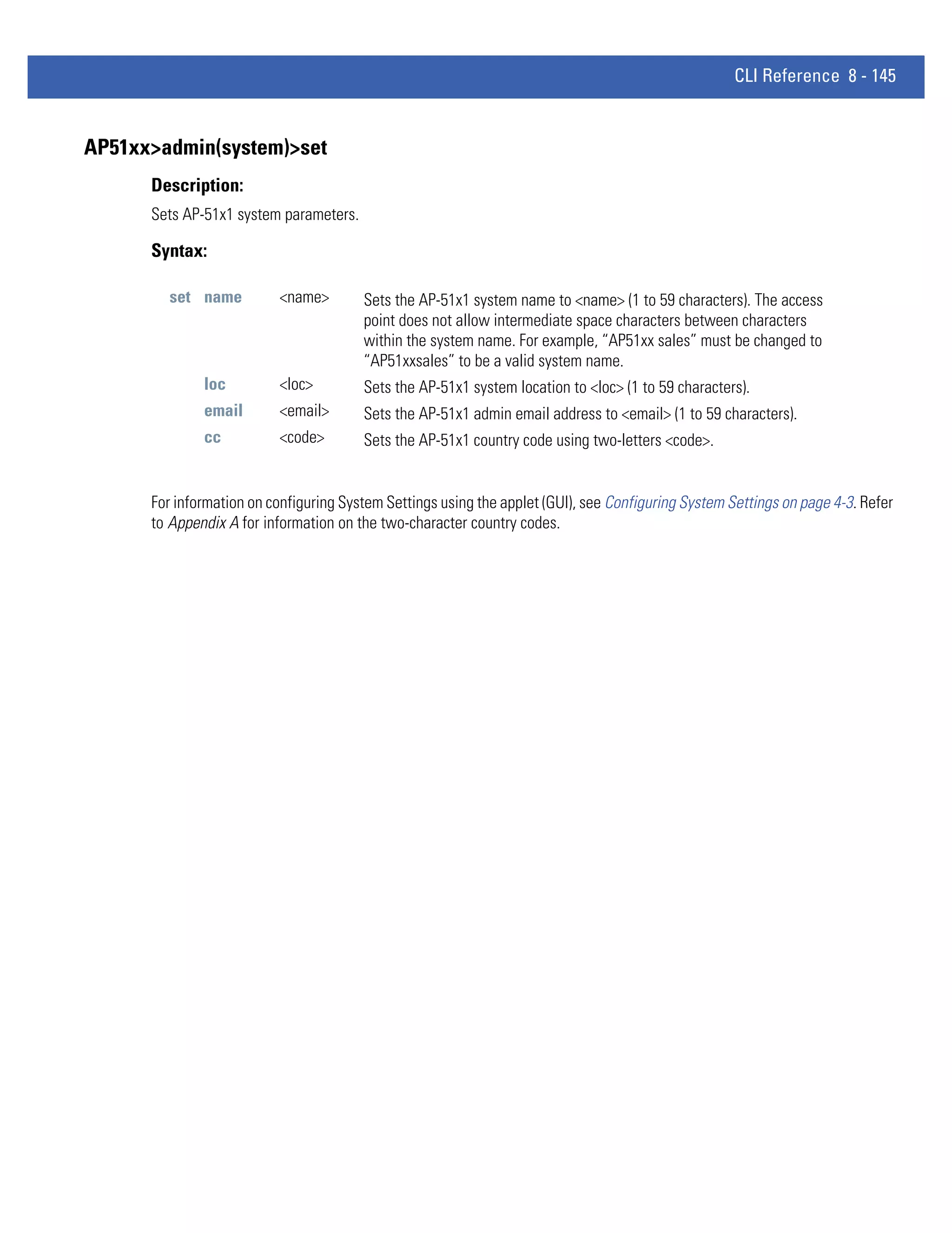
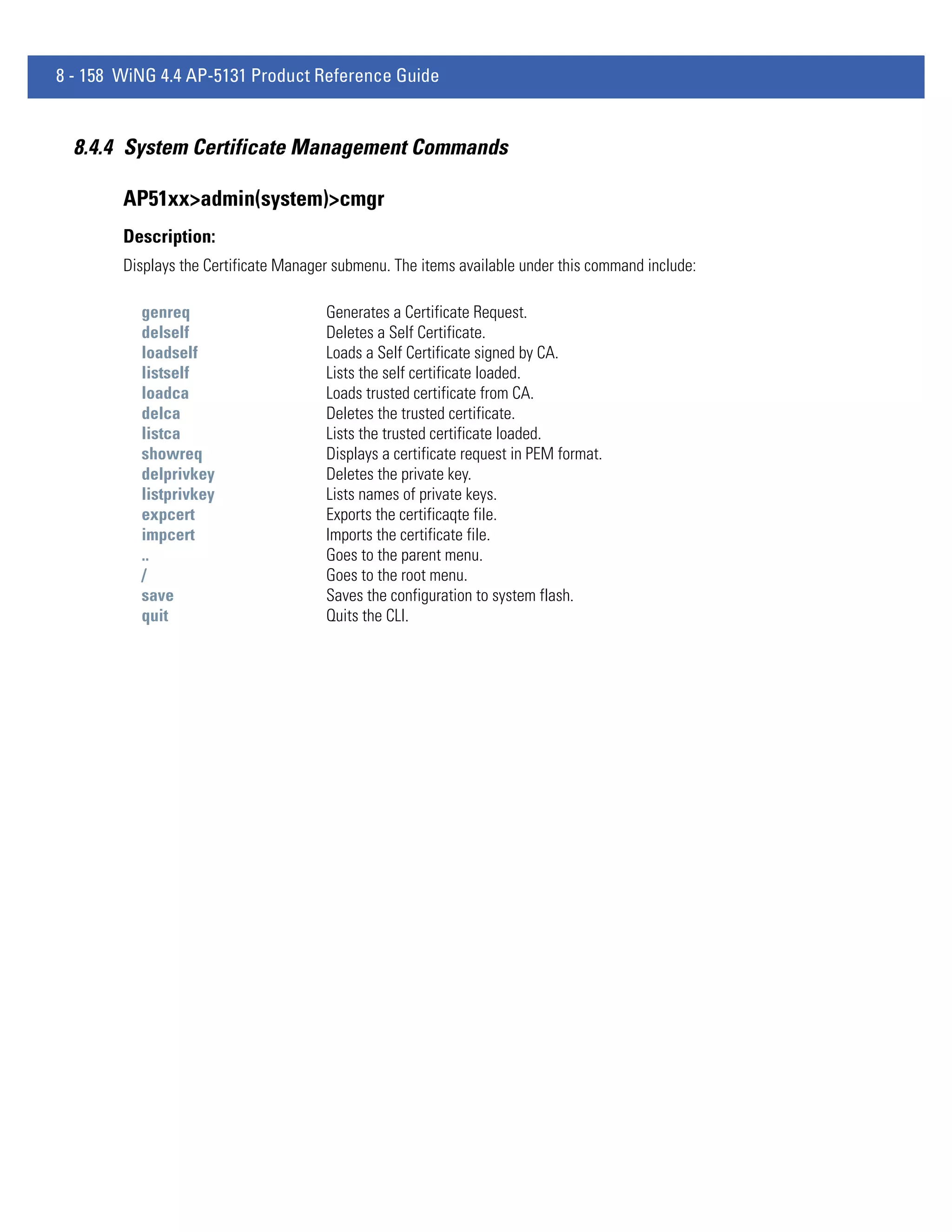
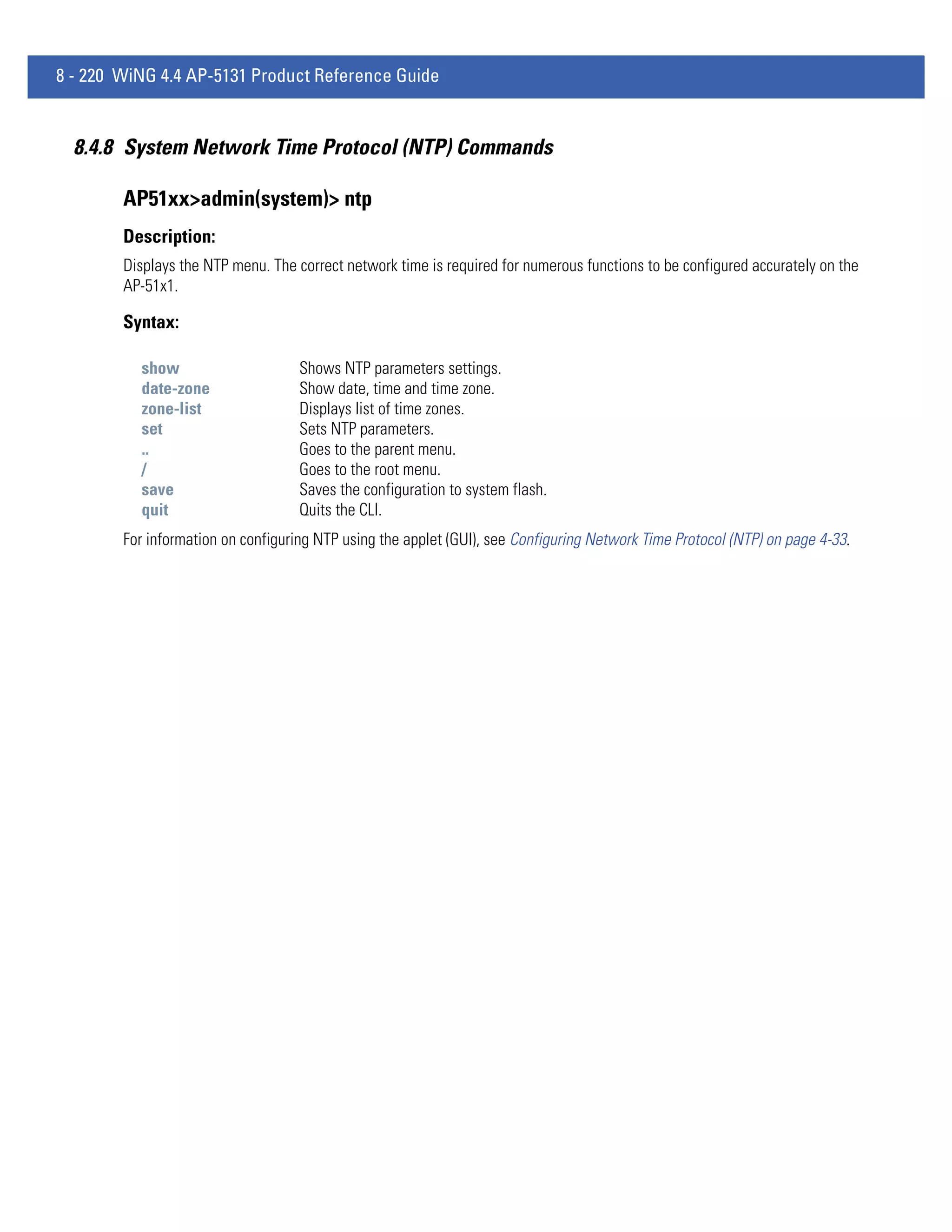
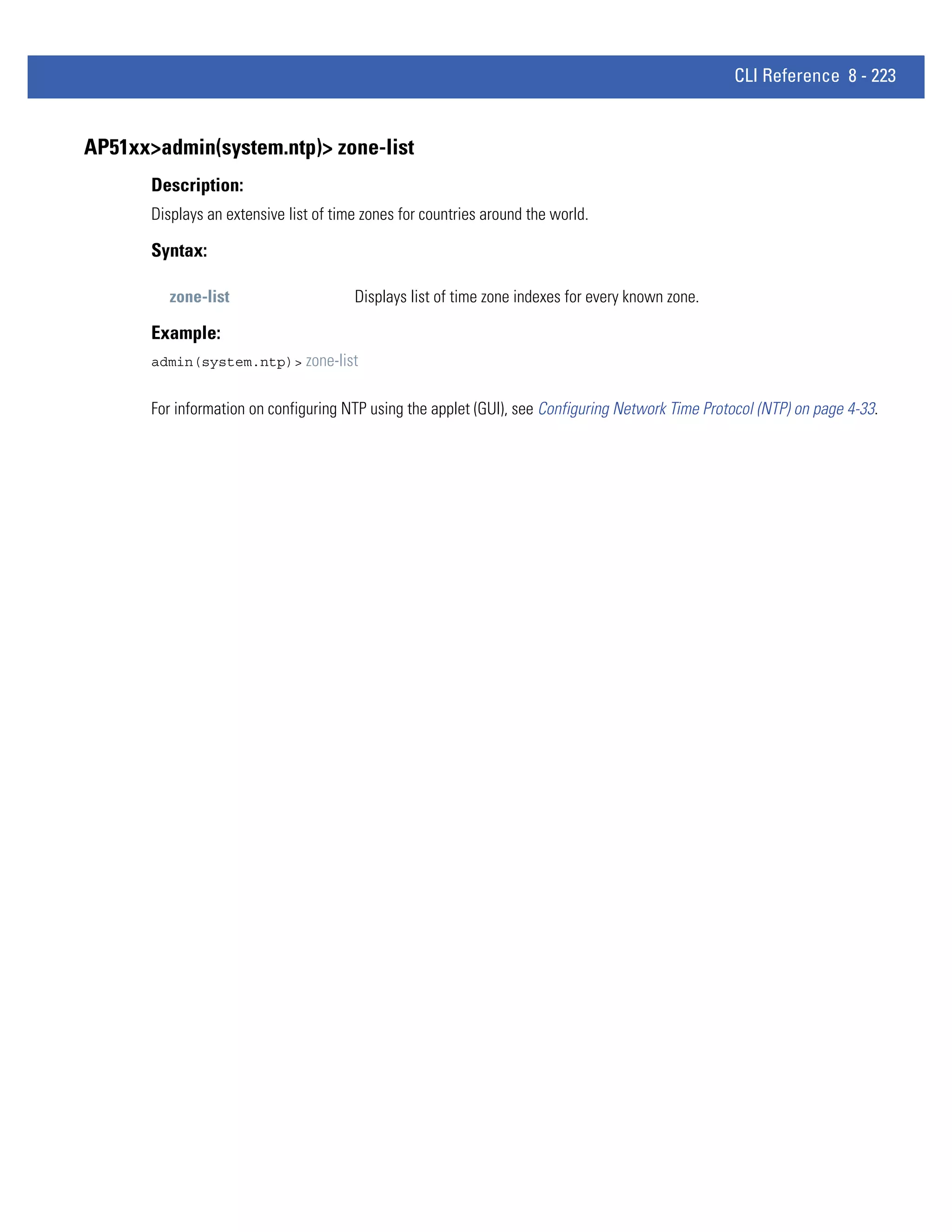
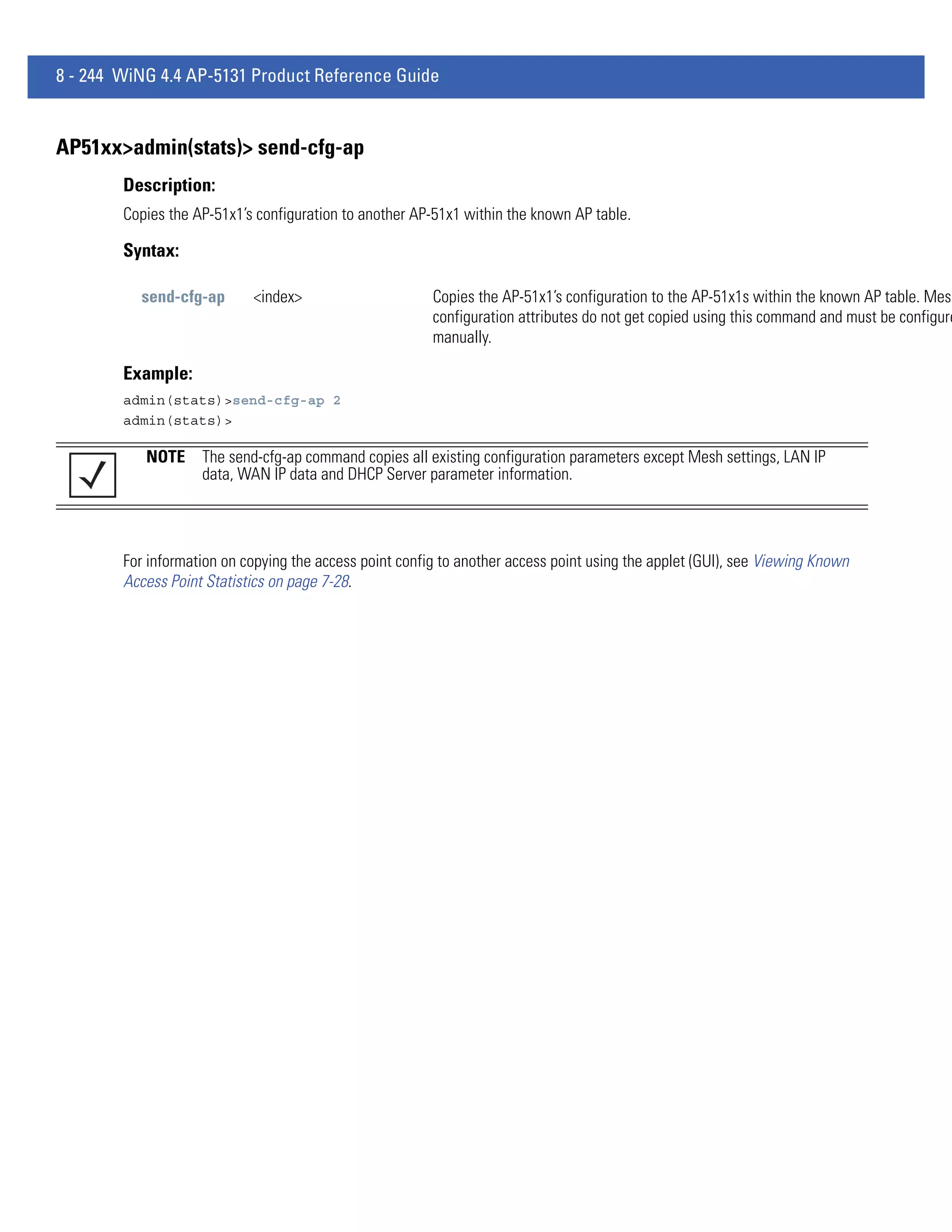
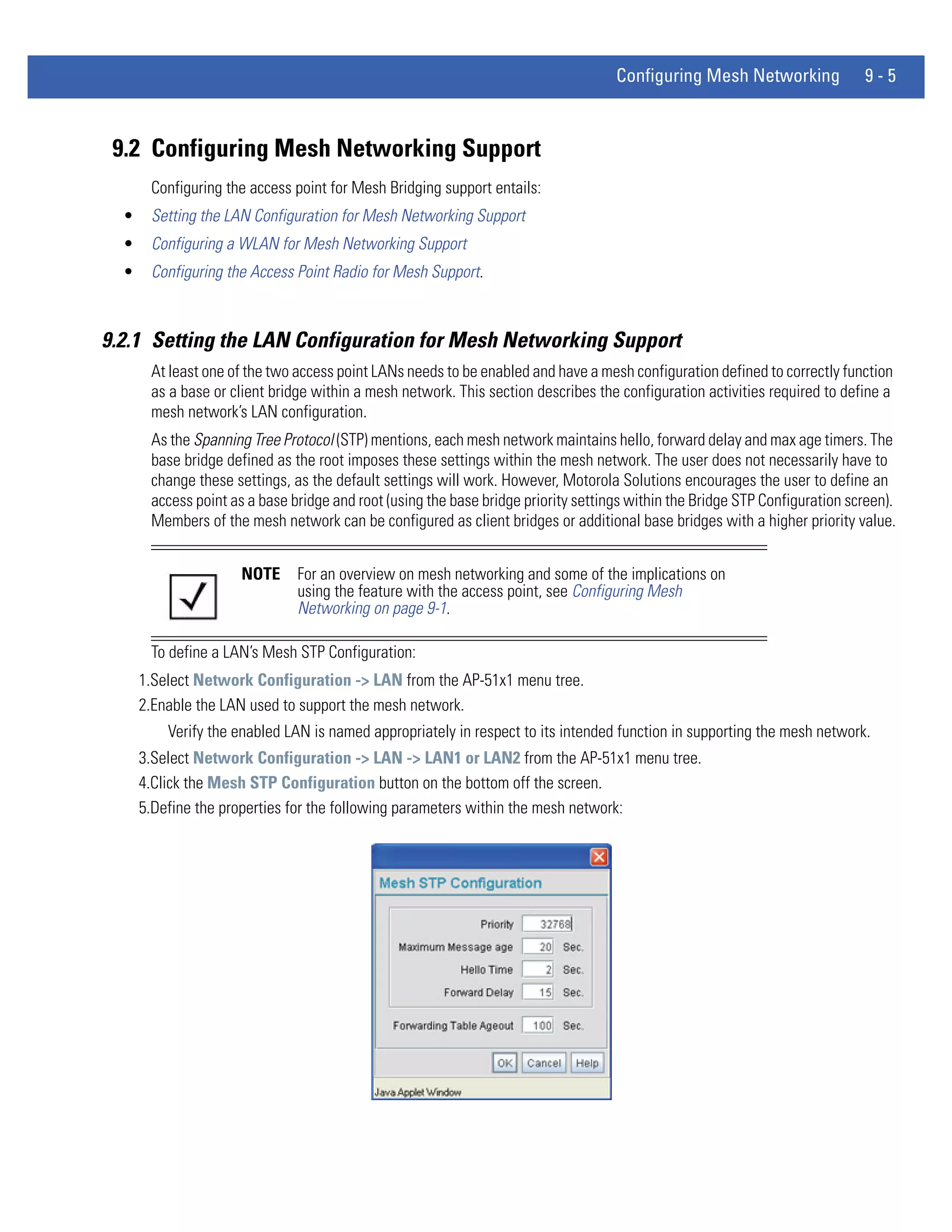
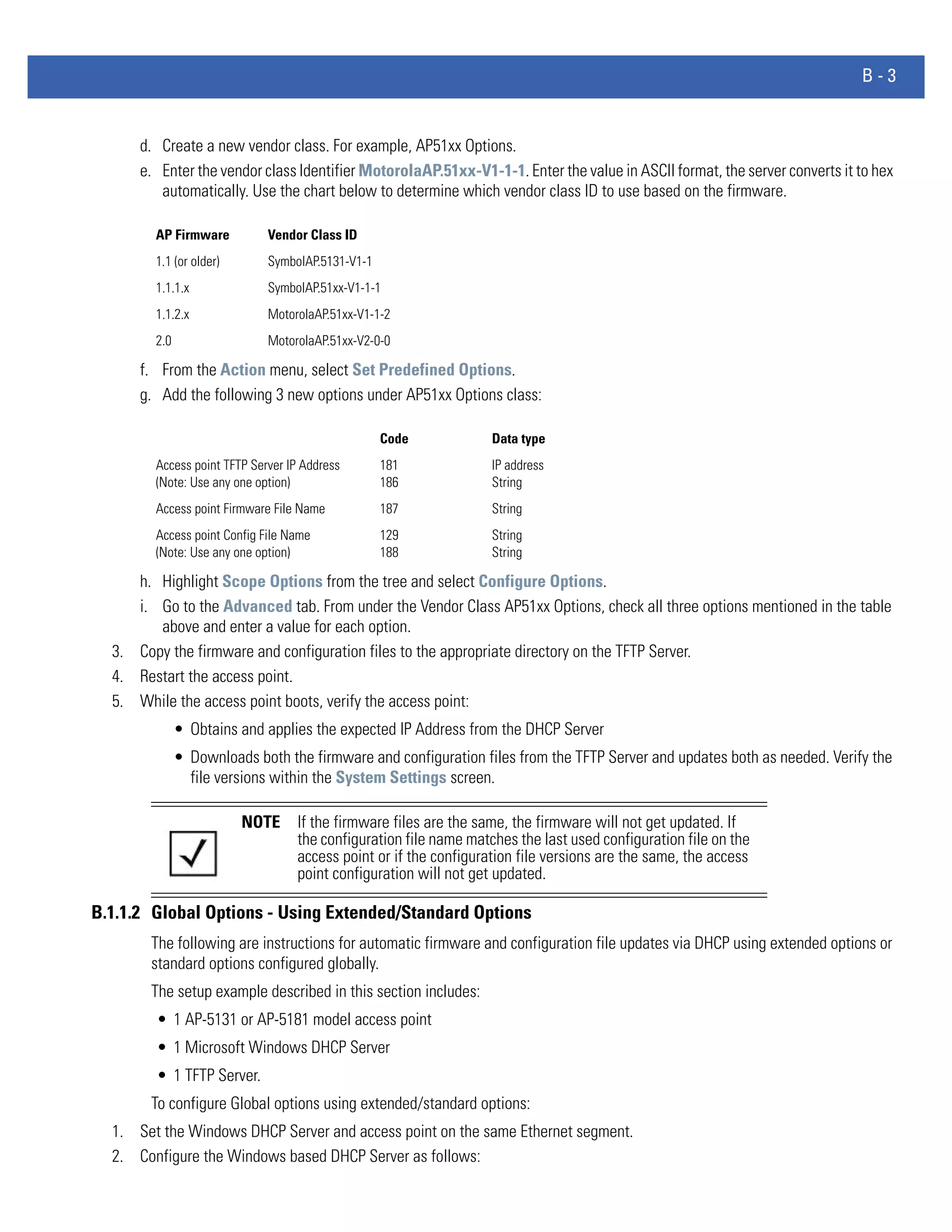
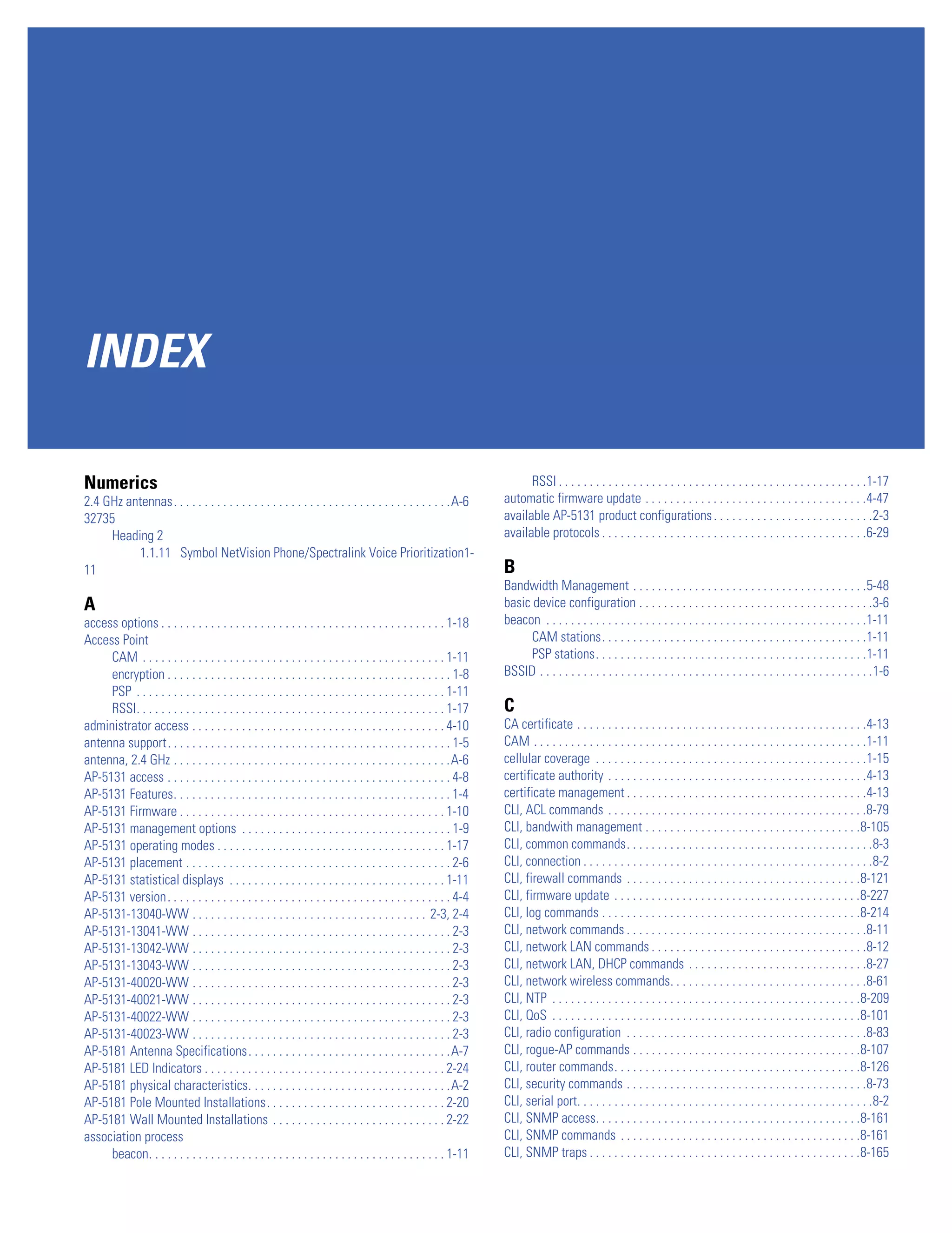
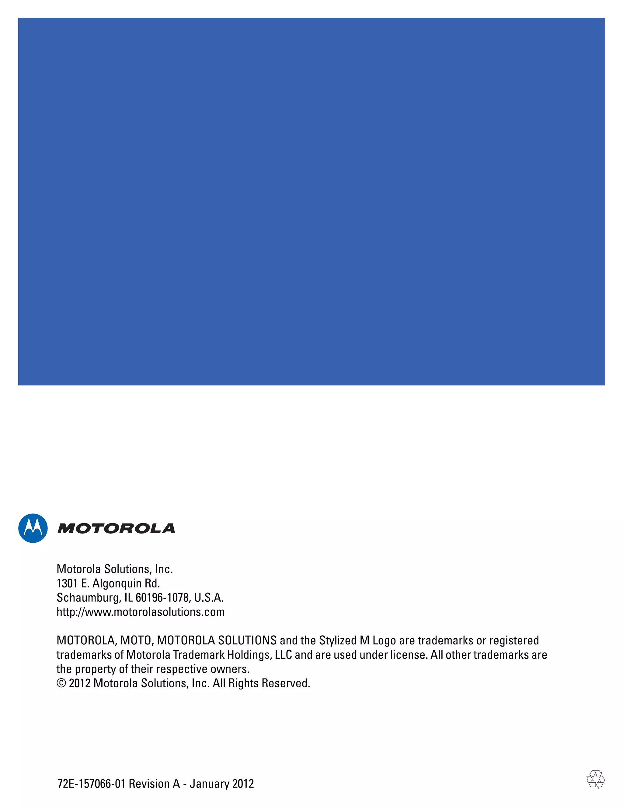
AP51xx>admin(system.ntp)> set
Description:
Sets NTP parameters for AP-51x1 clock synchronization.
Syntax:
set mode <ntp- Enables or disables NTP.
mode>
server <idx> Sets the NTP sever IP address.
<ip>
port <idx> Defines the port number.
<port>
intrvl <period Defines the clock synchronization interval used between the
> AP-51x1 and the NTP server in minutes (15 - 65535).
time <time> Sets the current system time. [yyyy] - year, [mm] - month, [dd] - day
of the month, [hh] - hour of the day, [mm] - minute, [ss] second, [zone
-idx] Index of the zone.
zone <zone> Defines the time zone (by index) for the target country.
Example:
admin(system.ntp)>set mode enable
admin(system.ntp)>set server 1 203.21.37.18
admin(system.ntp)>set port 1 123
admin(system.ntp)>set intrvl 15
admin(system.ntp)>set zone 1
For information on configuring NTP using the applet (GUI), see Configuring Network Time Protocol (NTP) on page 4-33.](https://image.slidesharecdn.com/motorolasolutionswing4-4ap51xxaccesspointproductreferenceguidepartno-72e-157066-01rev-a-120807142110-phpapp02/75/Motorola-solutions-wing-4-4-ap51xx-access-point-product-reference-guide-part-no-72-e-157066-01-rev-a-494-2048.jpg)
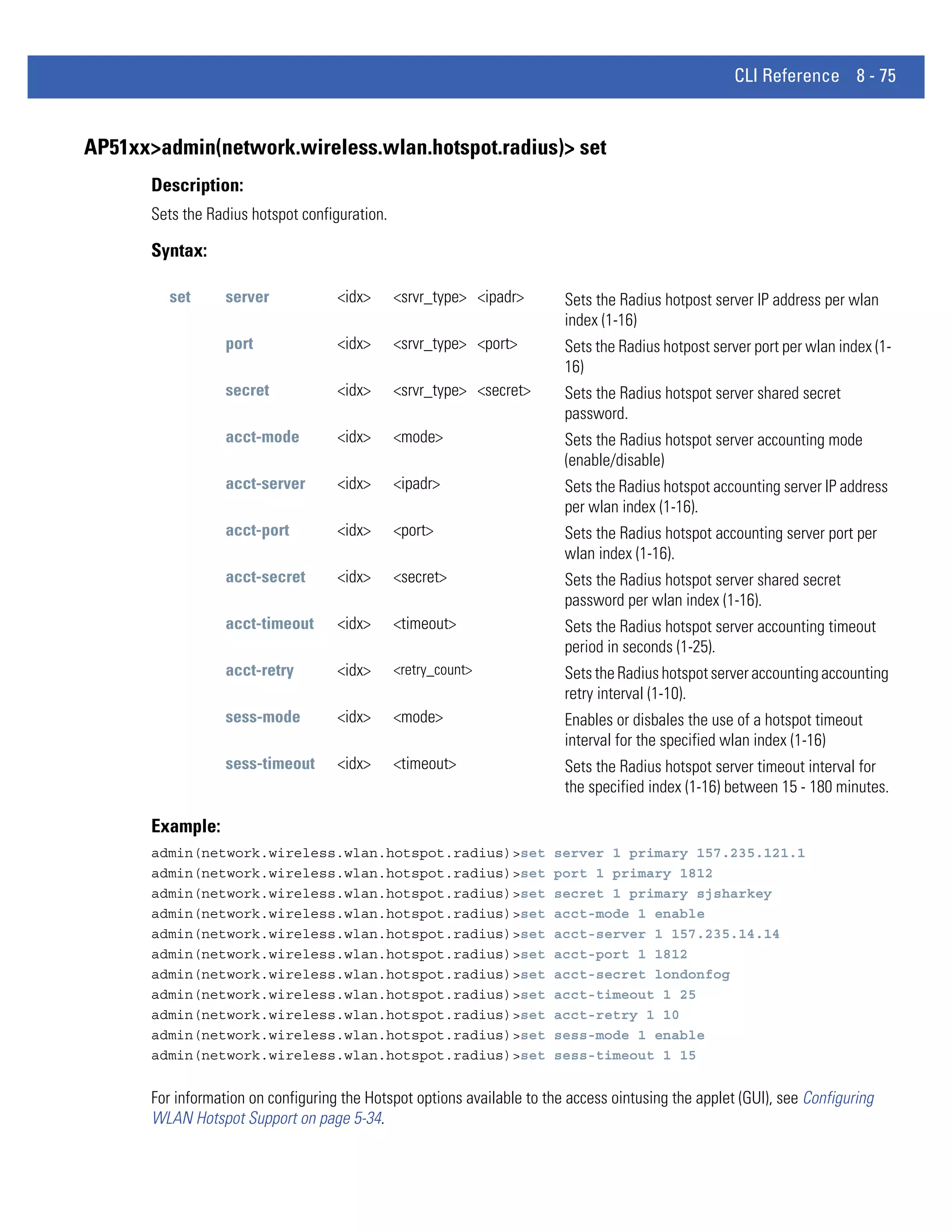
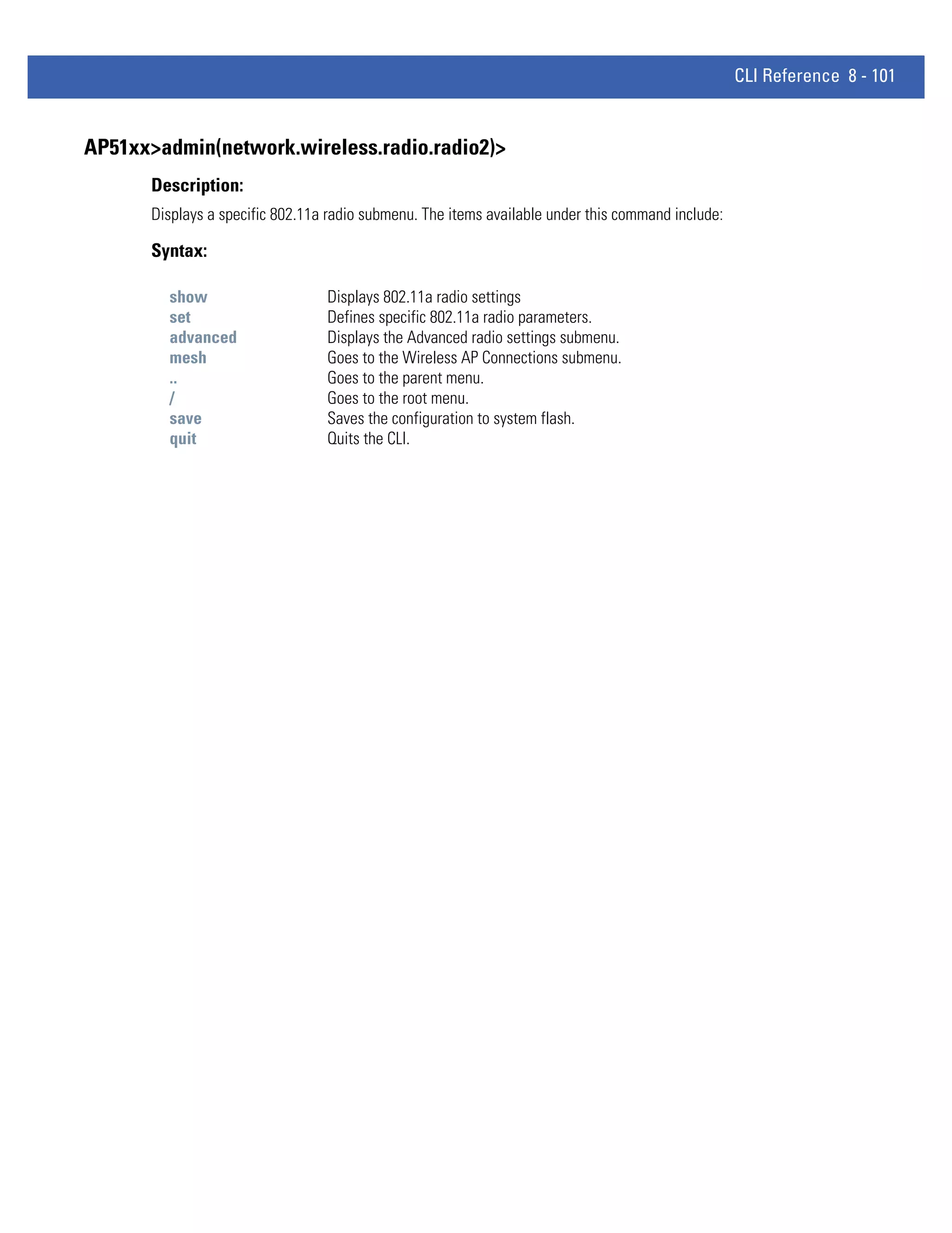
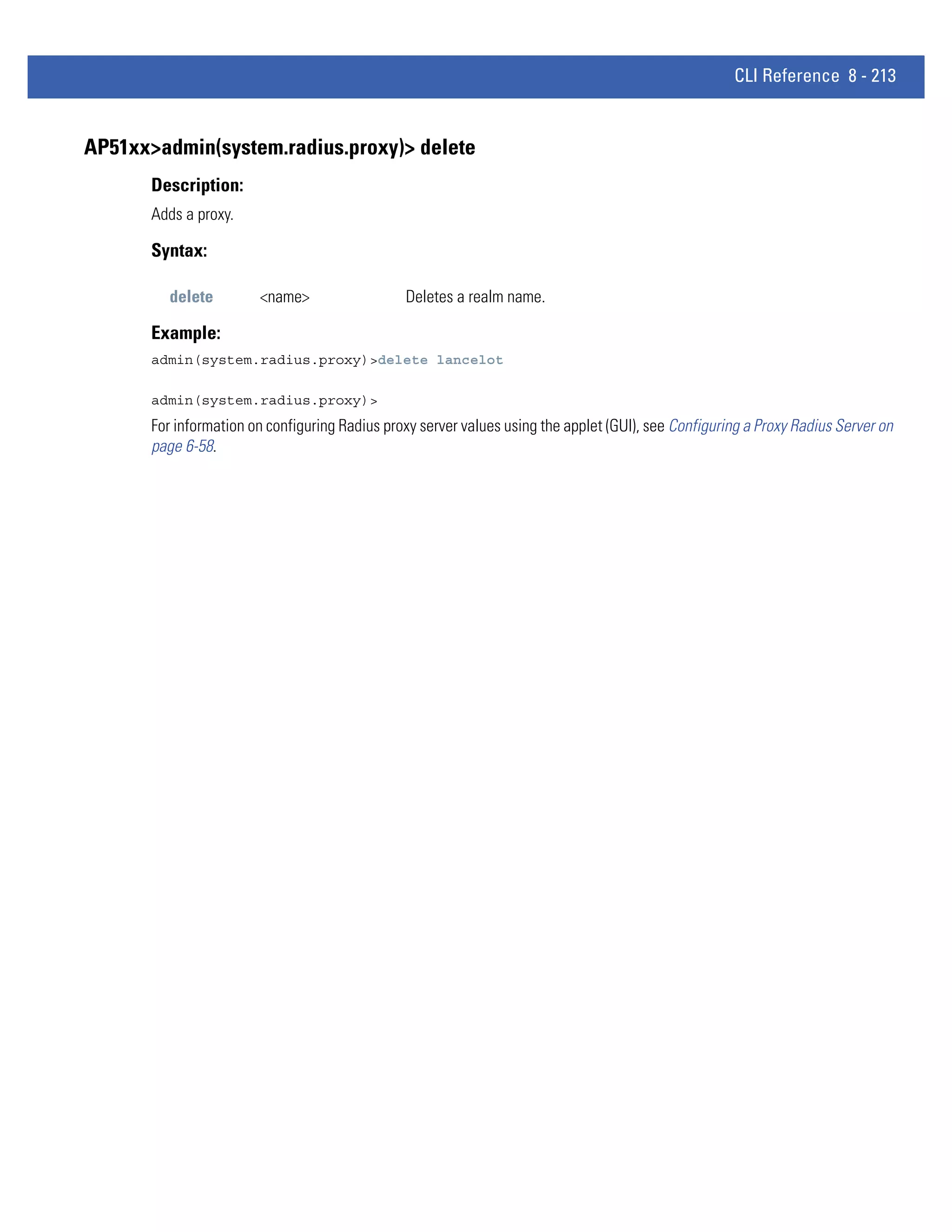
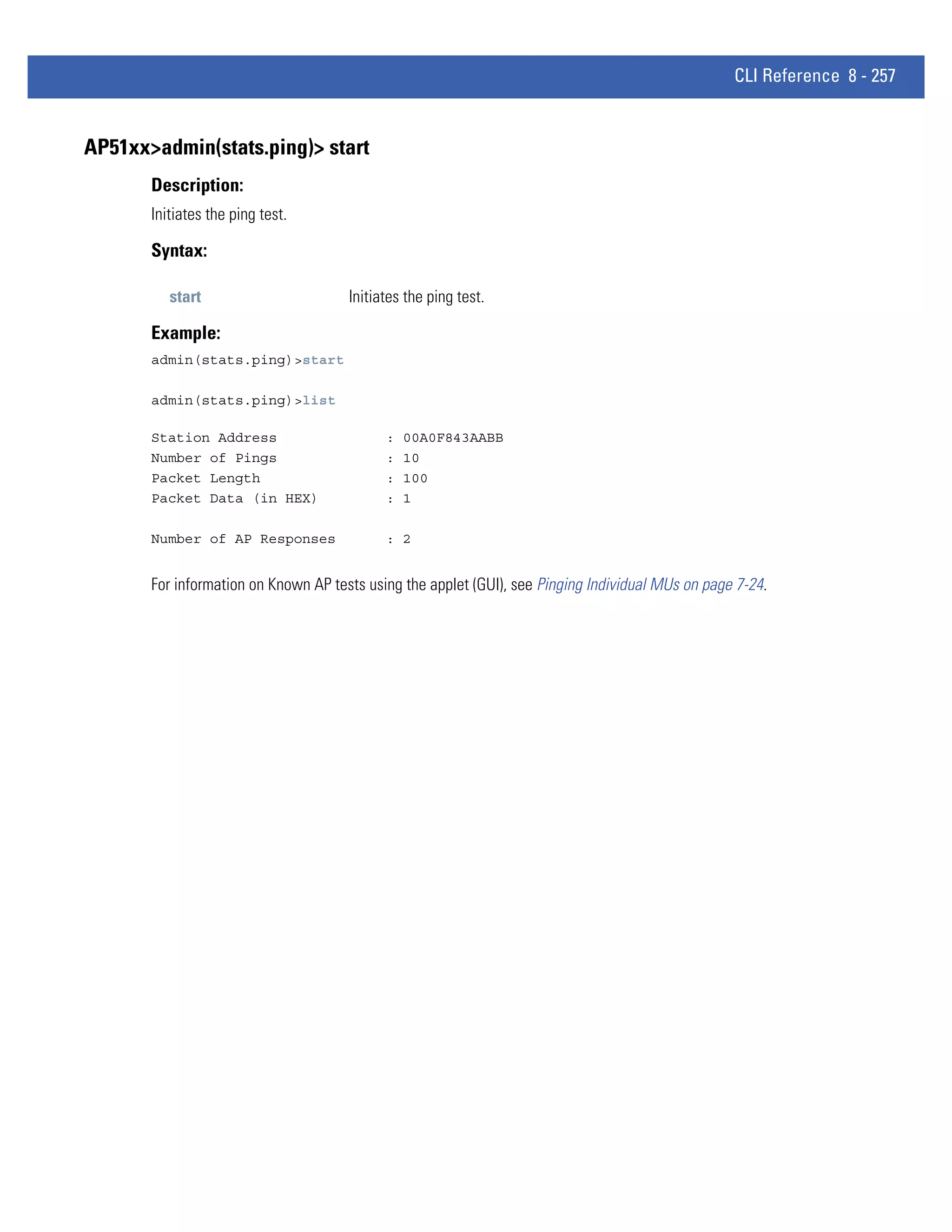
![8 - 230 WiNG 4.4 AP-5131 Product Reference Guide
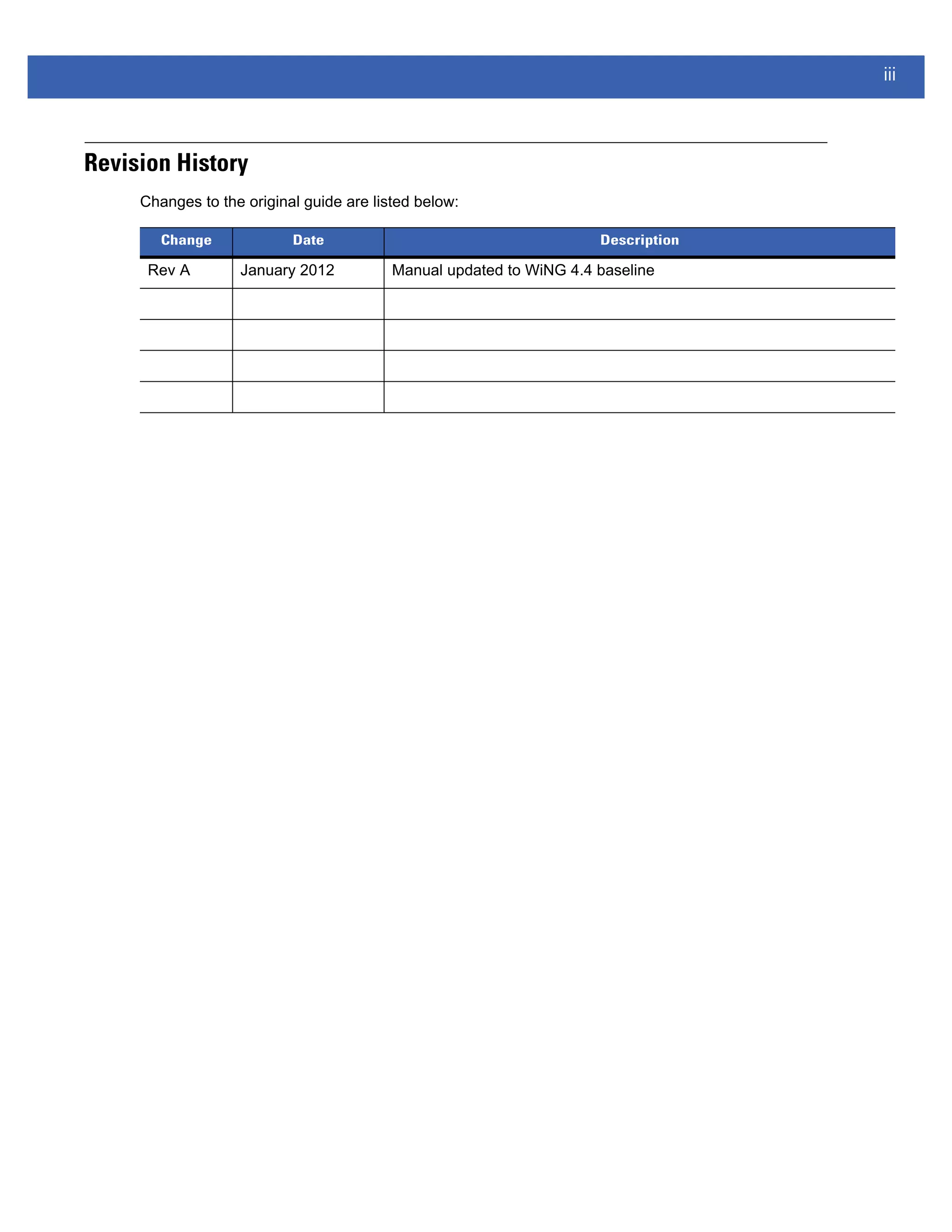
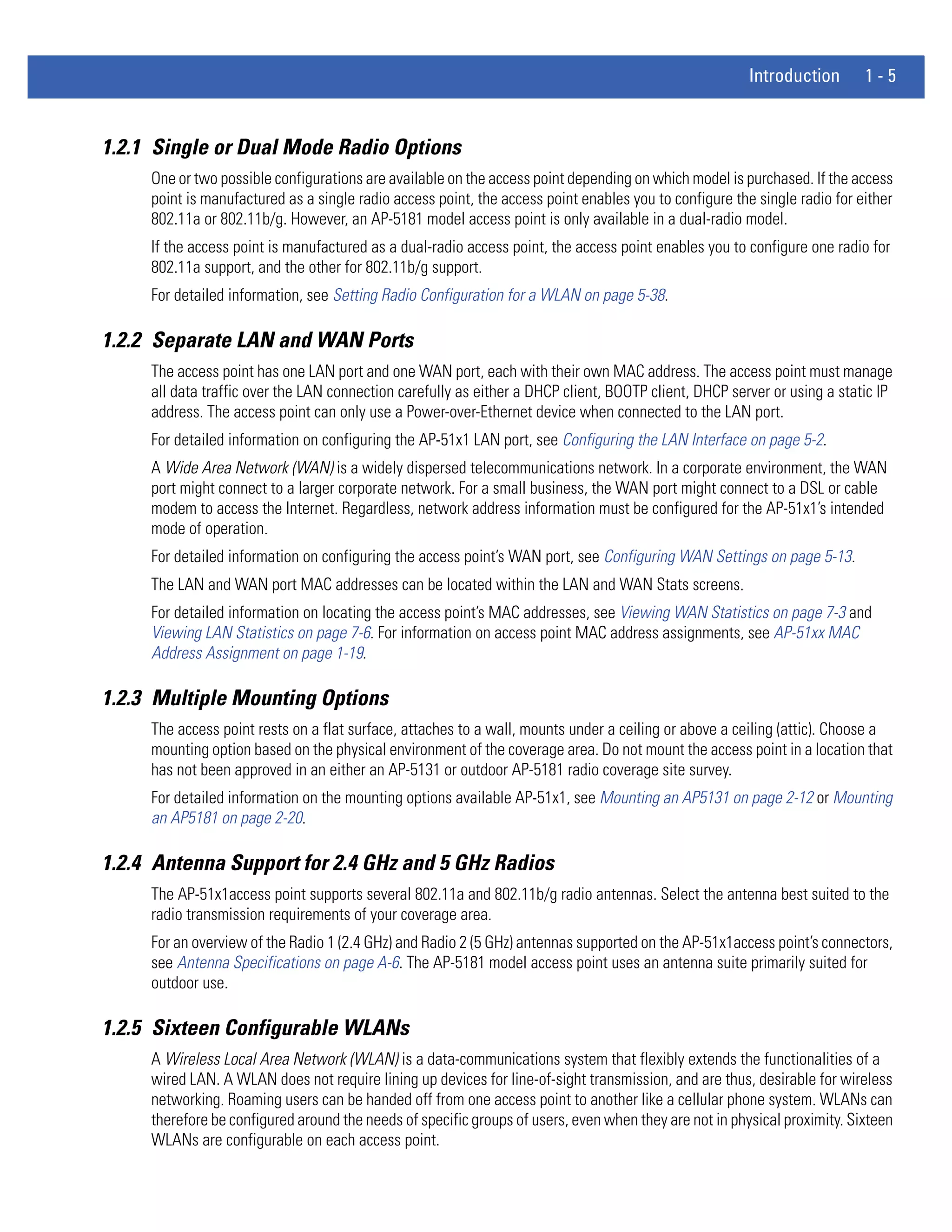
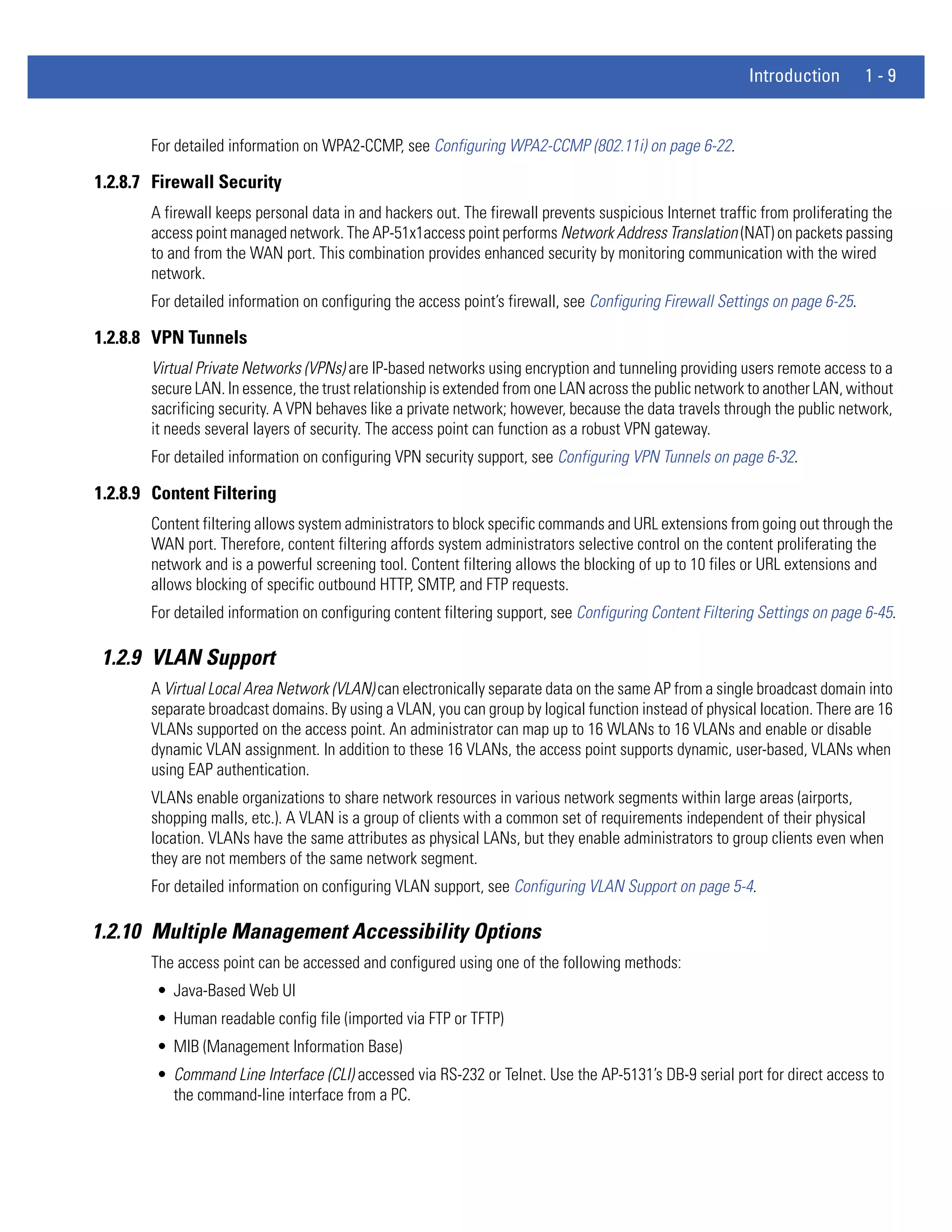
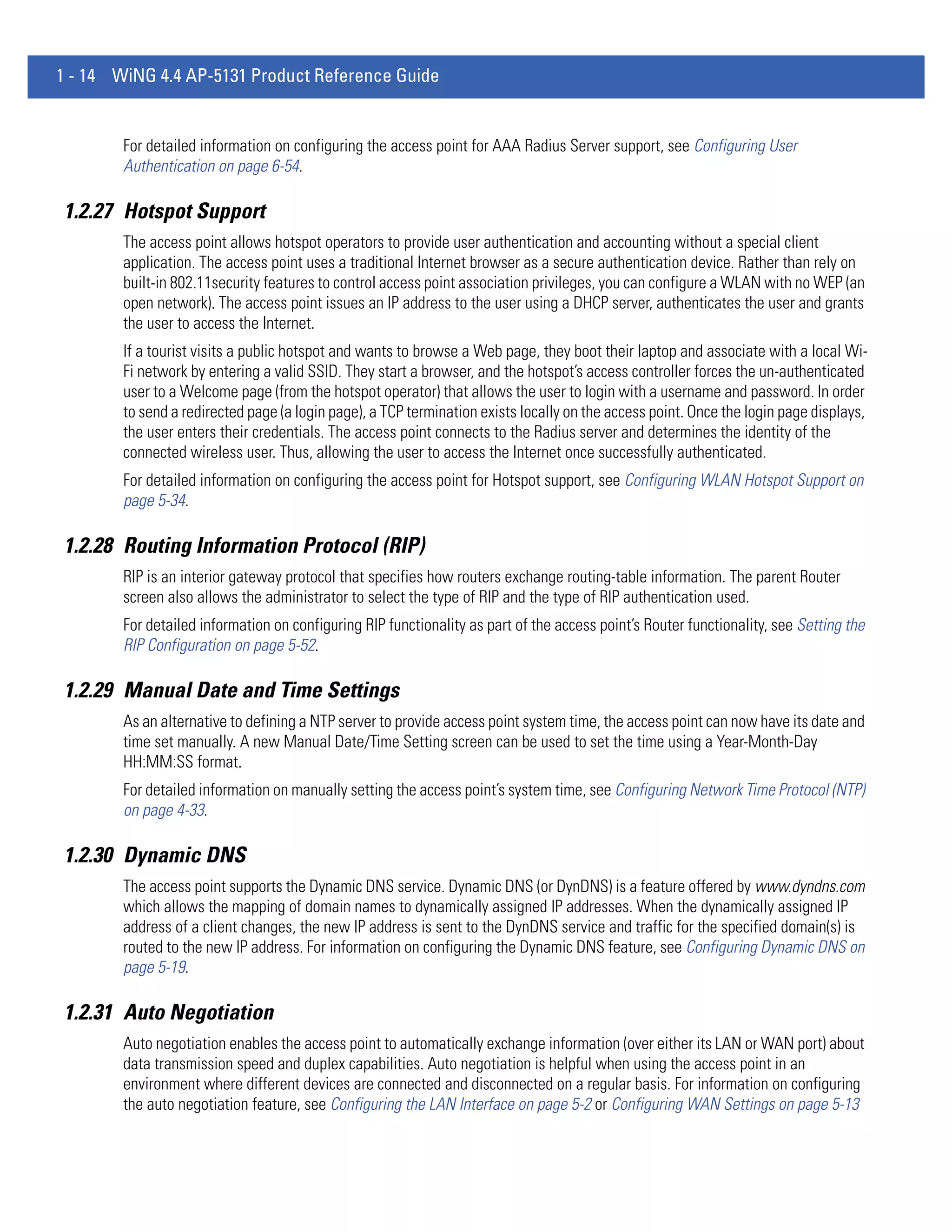
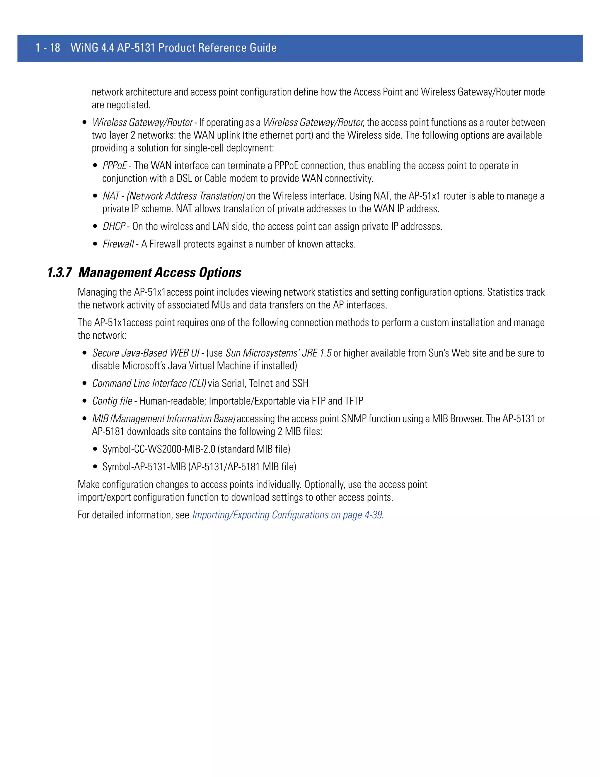
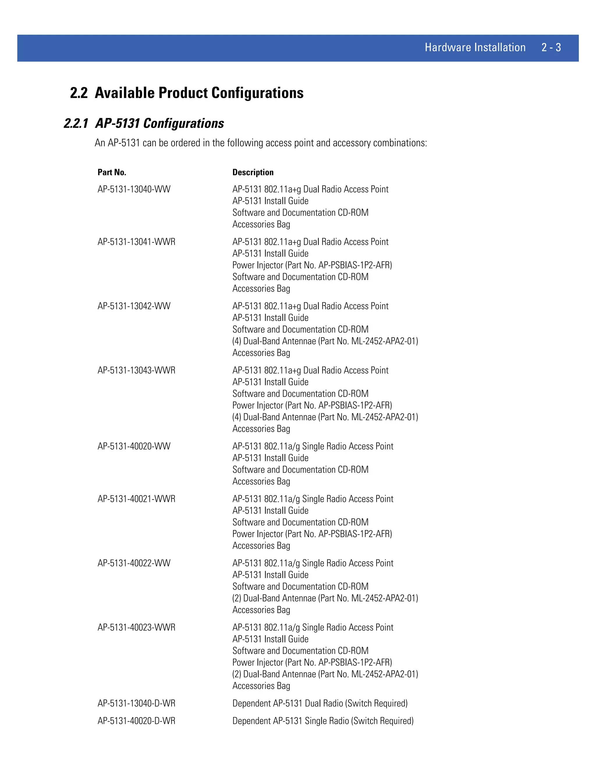
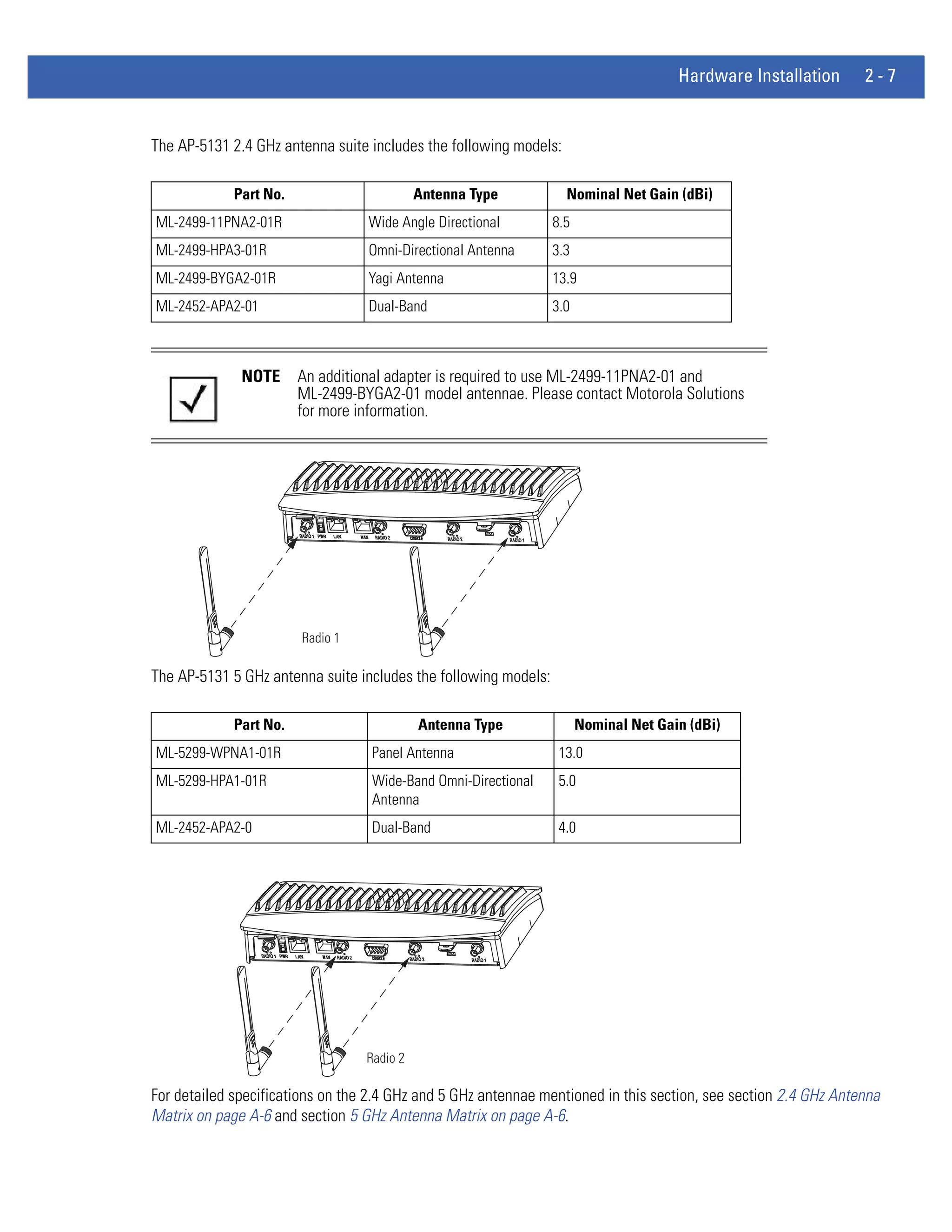
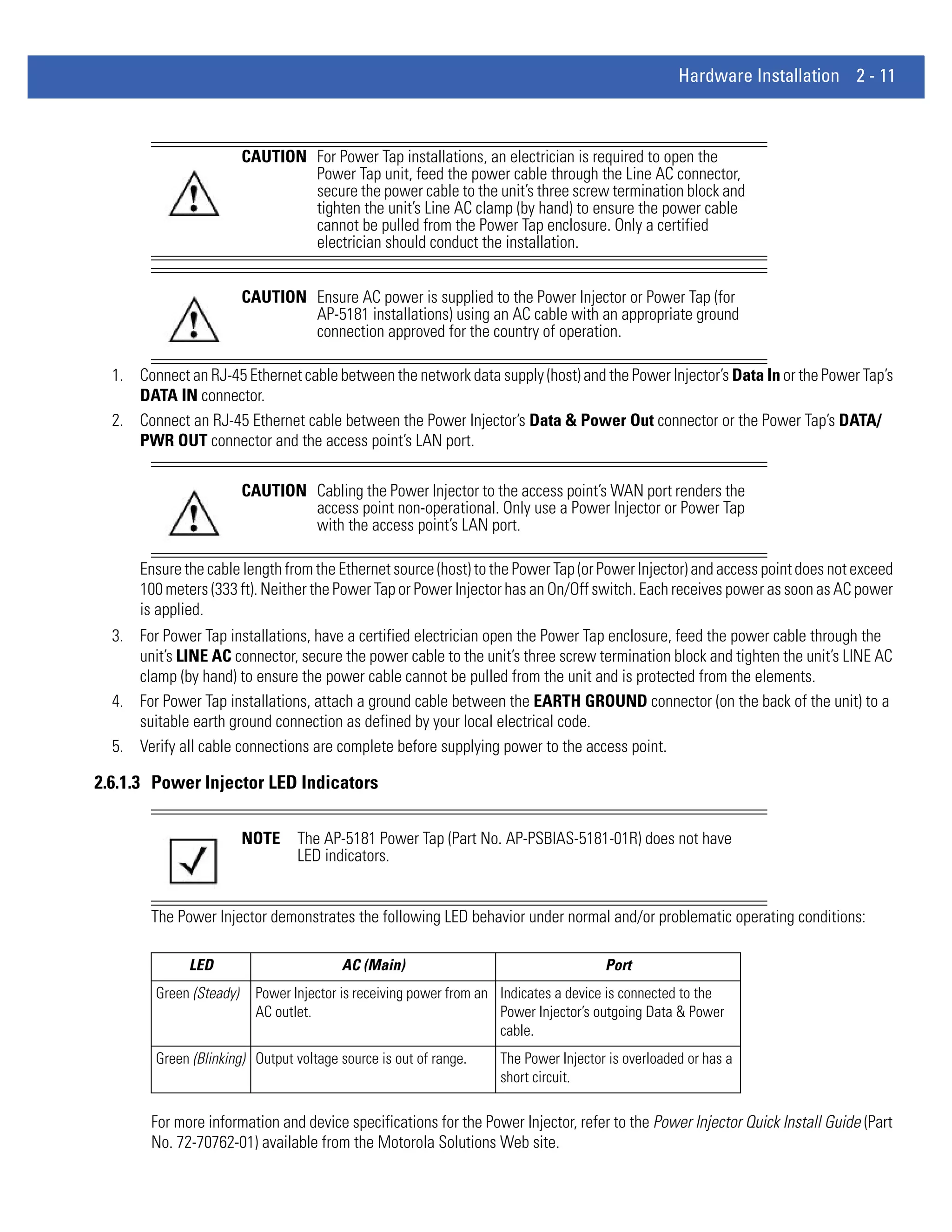
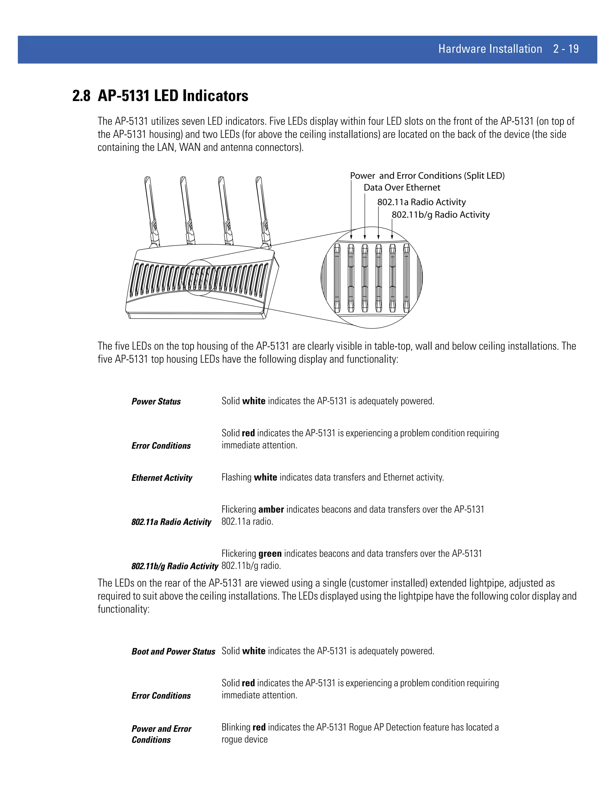
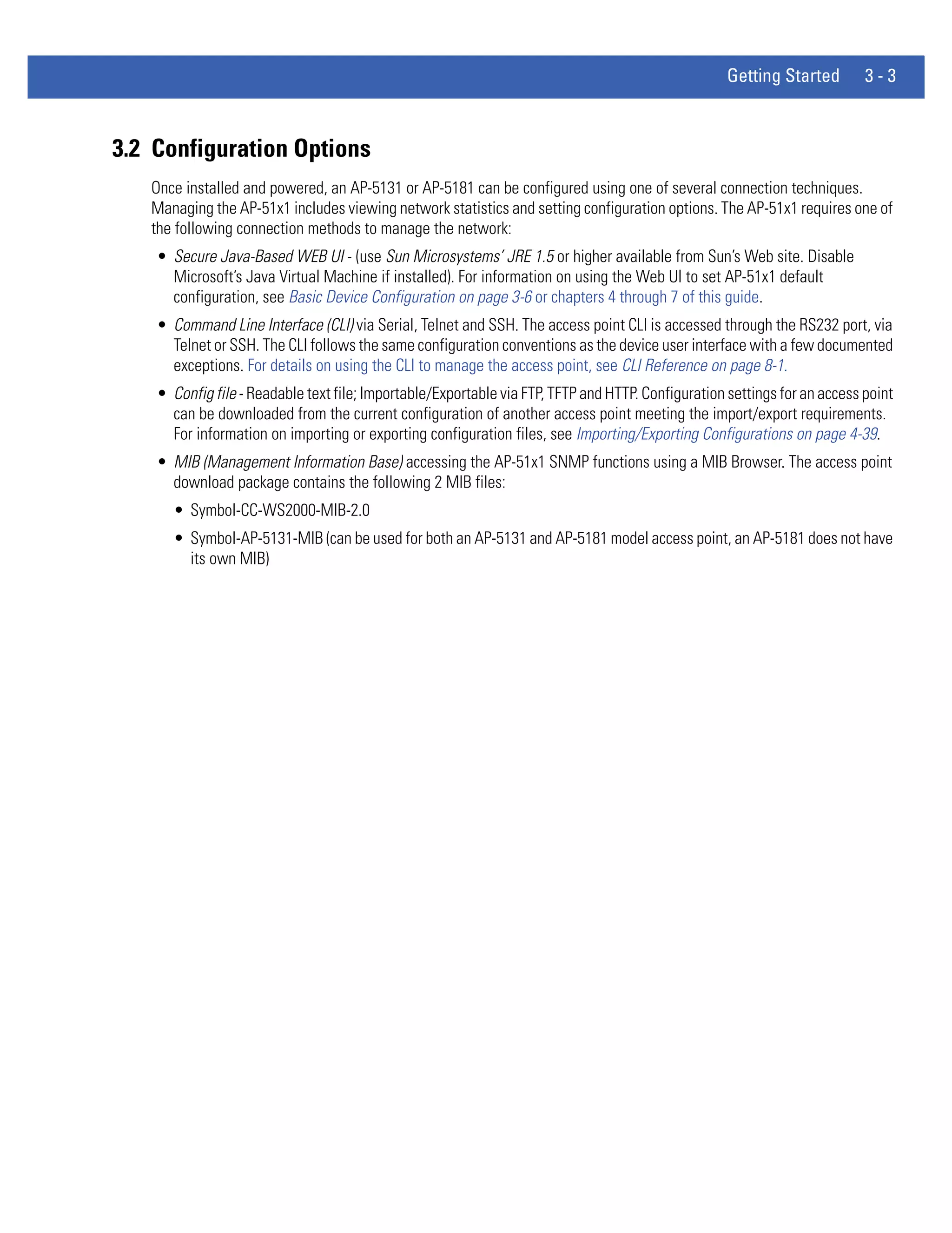
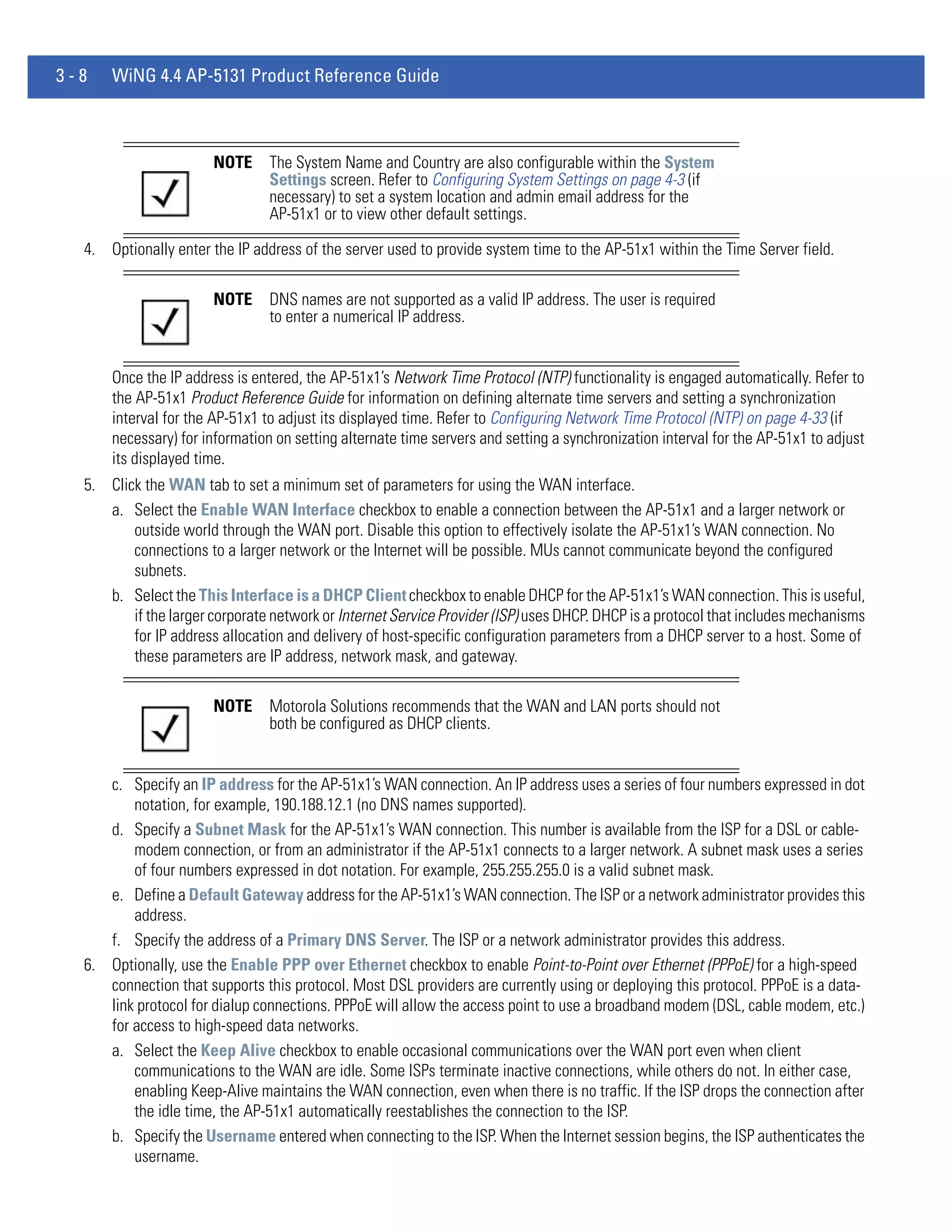
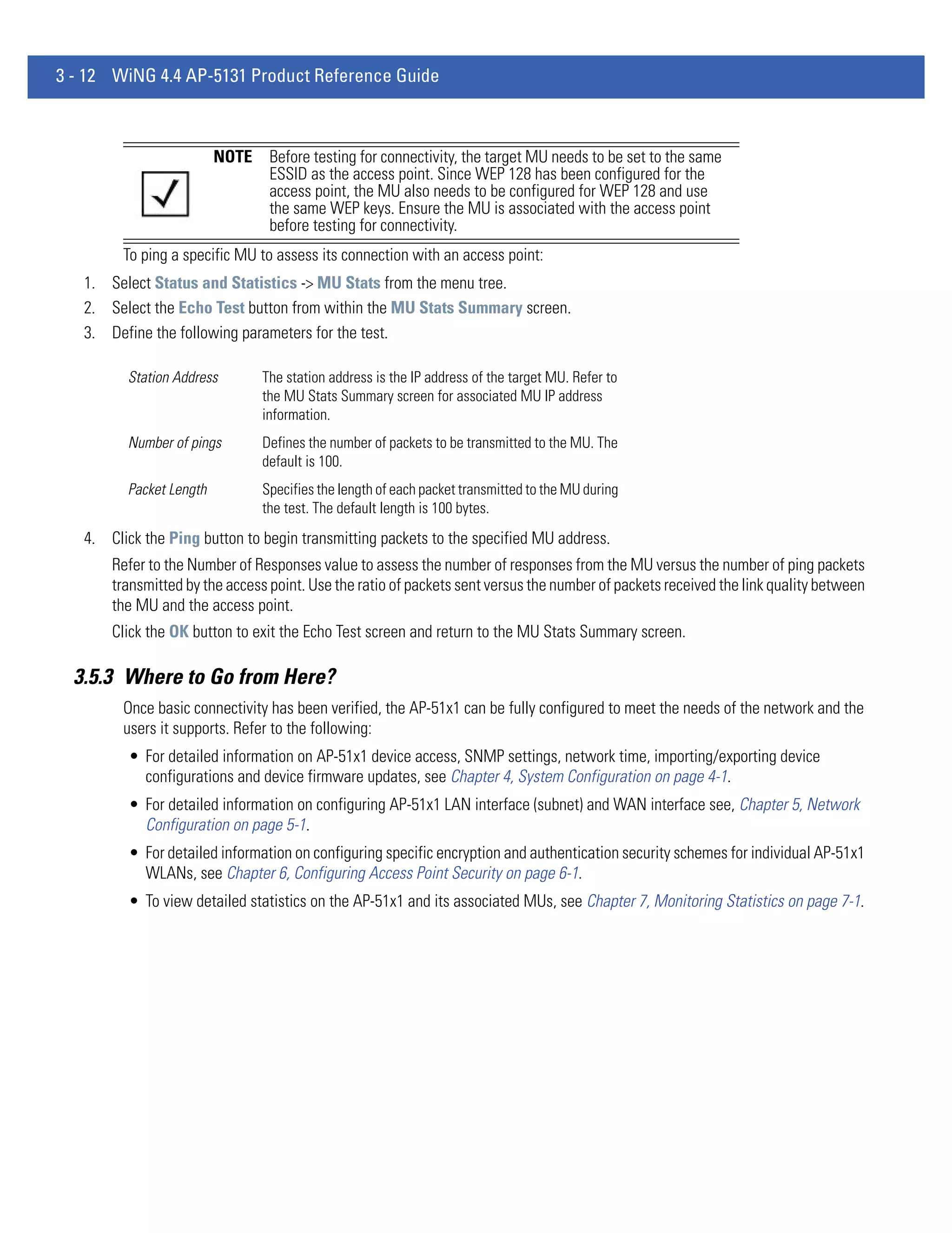
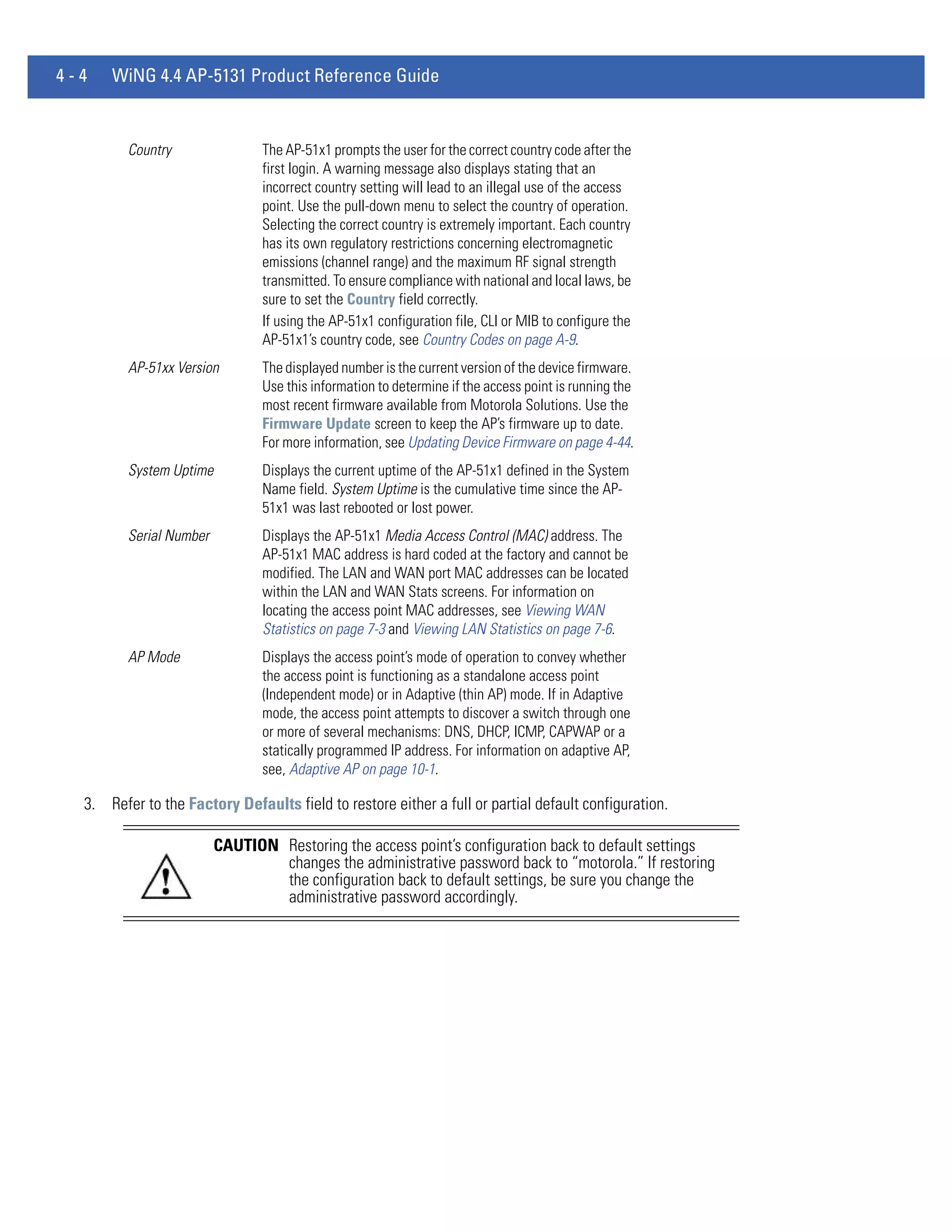
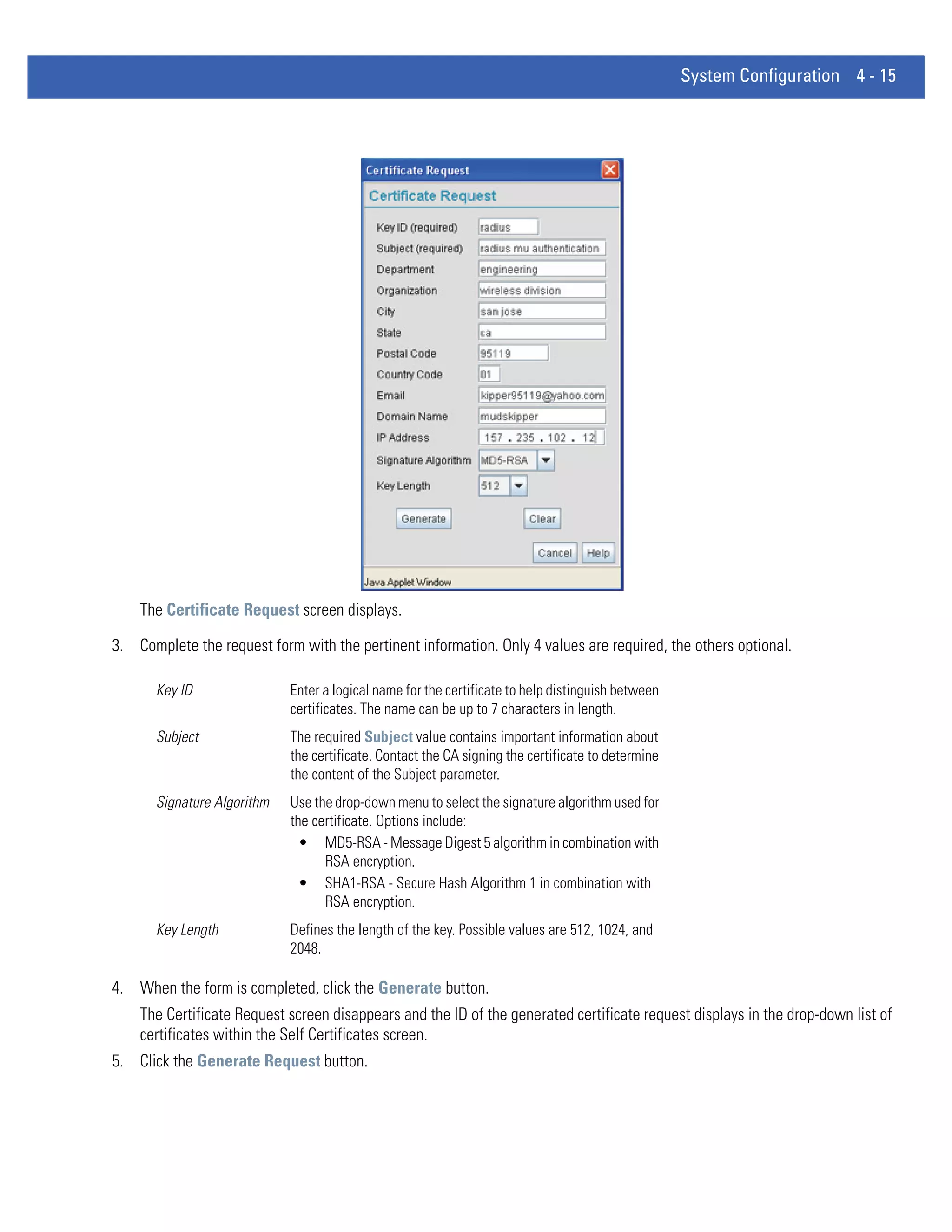
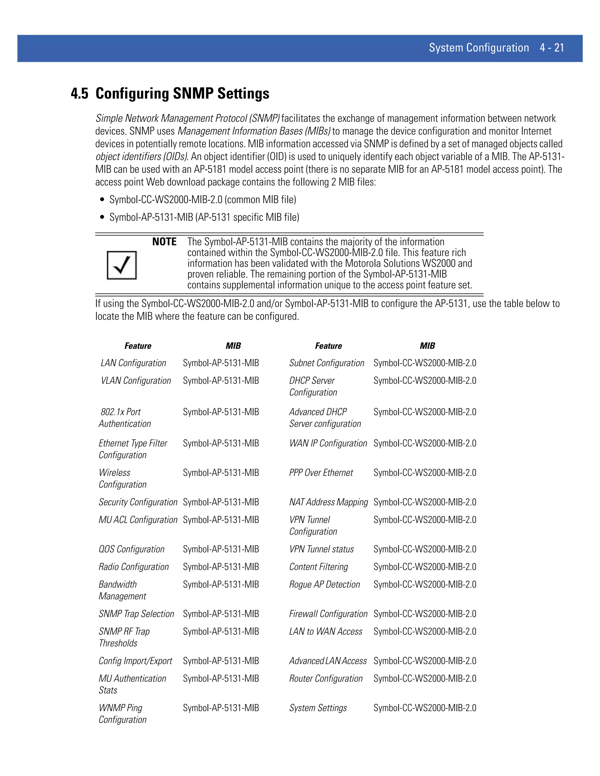
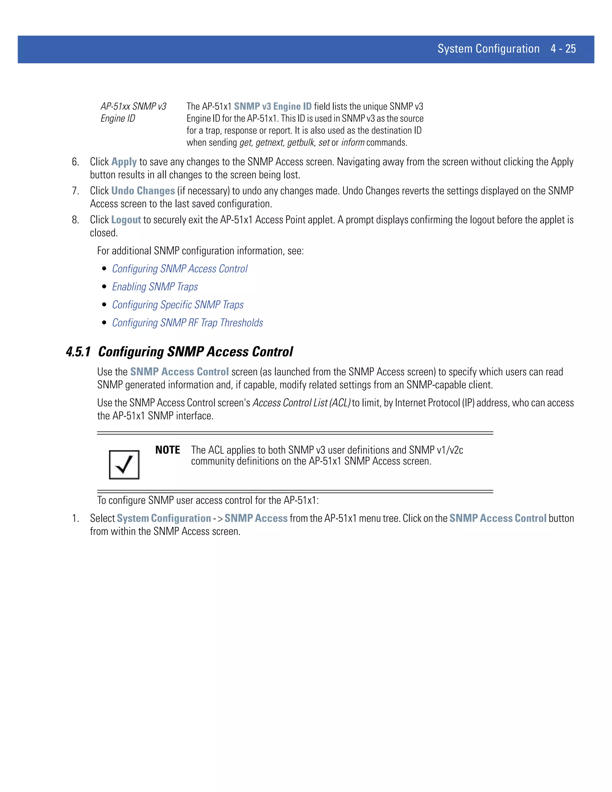
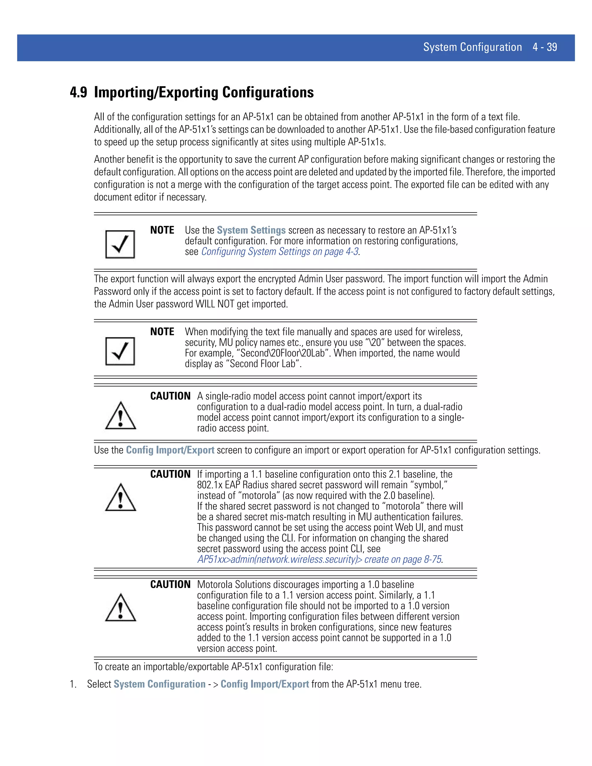
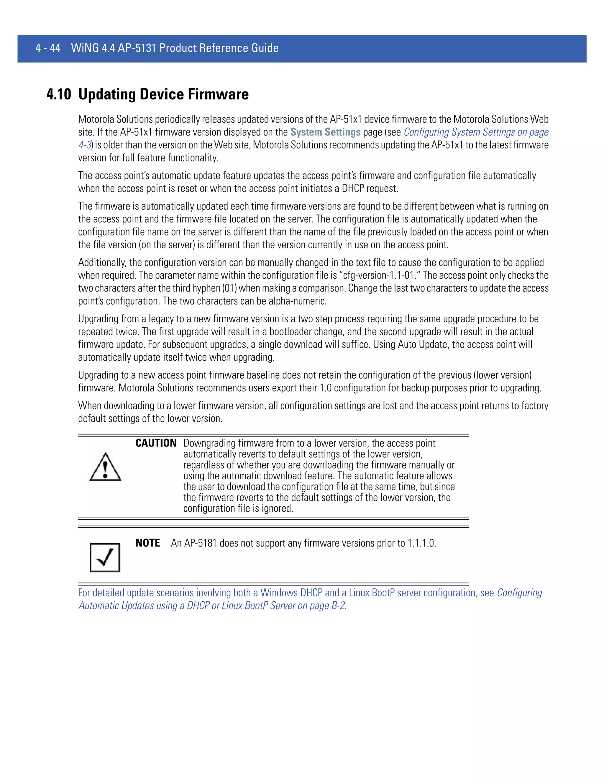
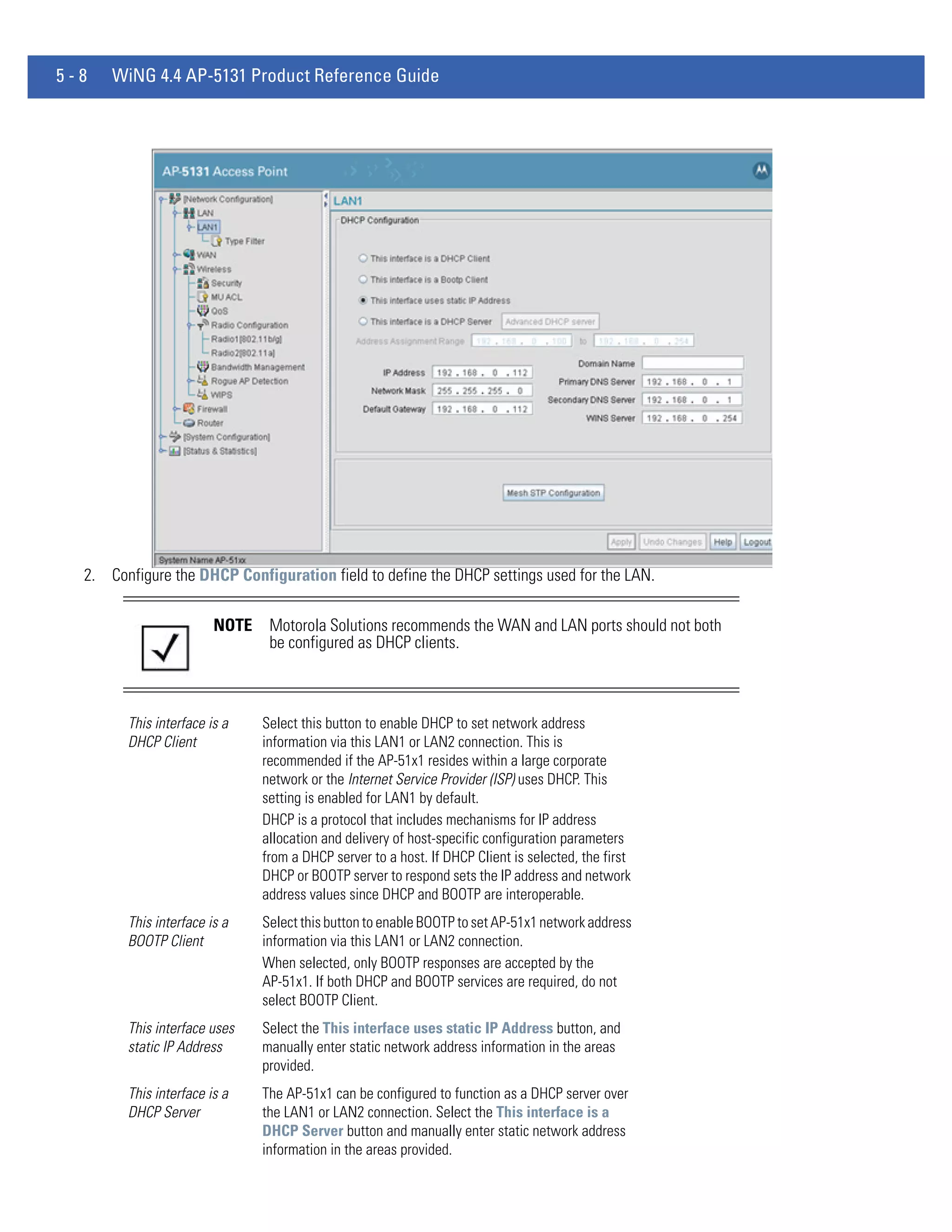
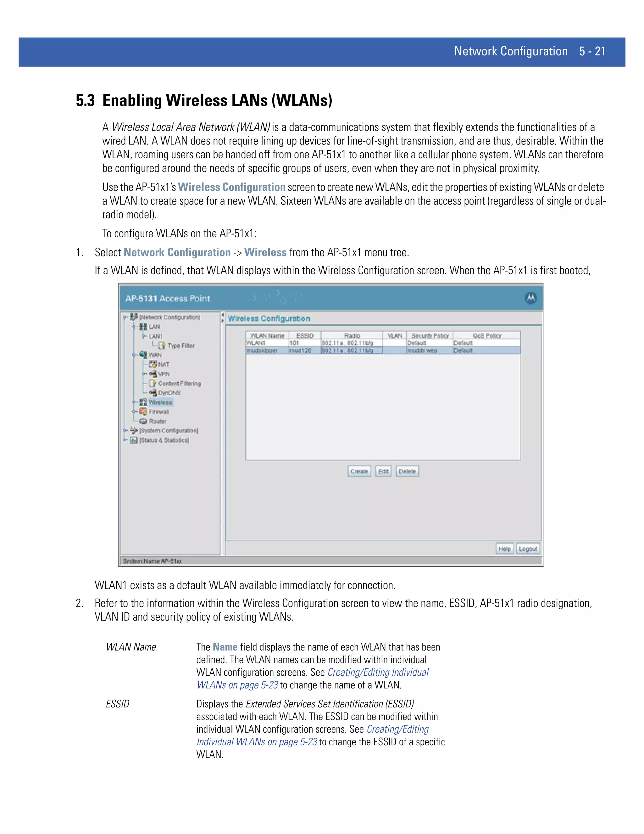
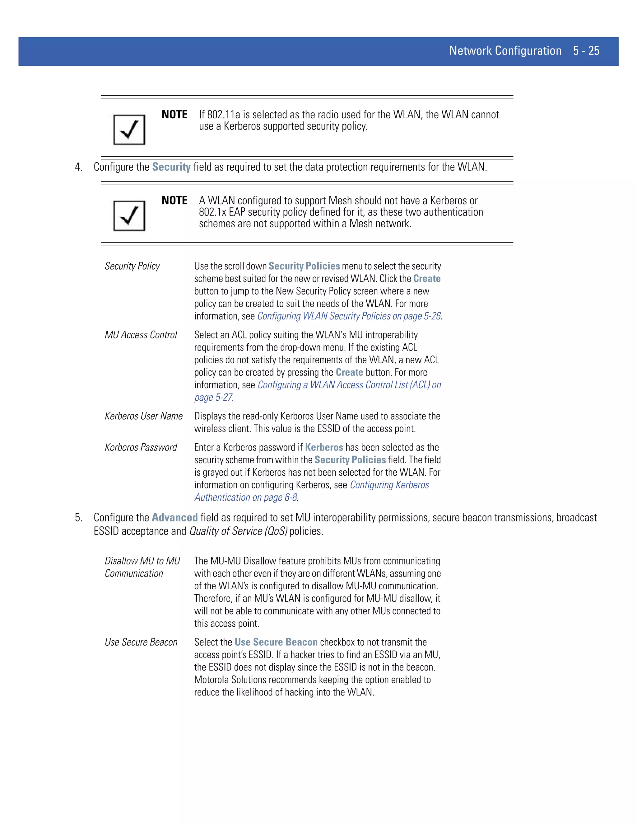
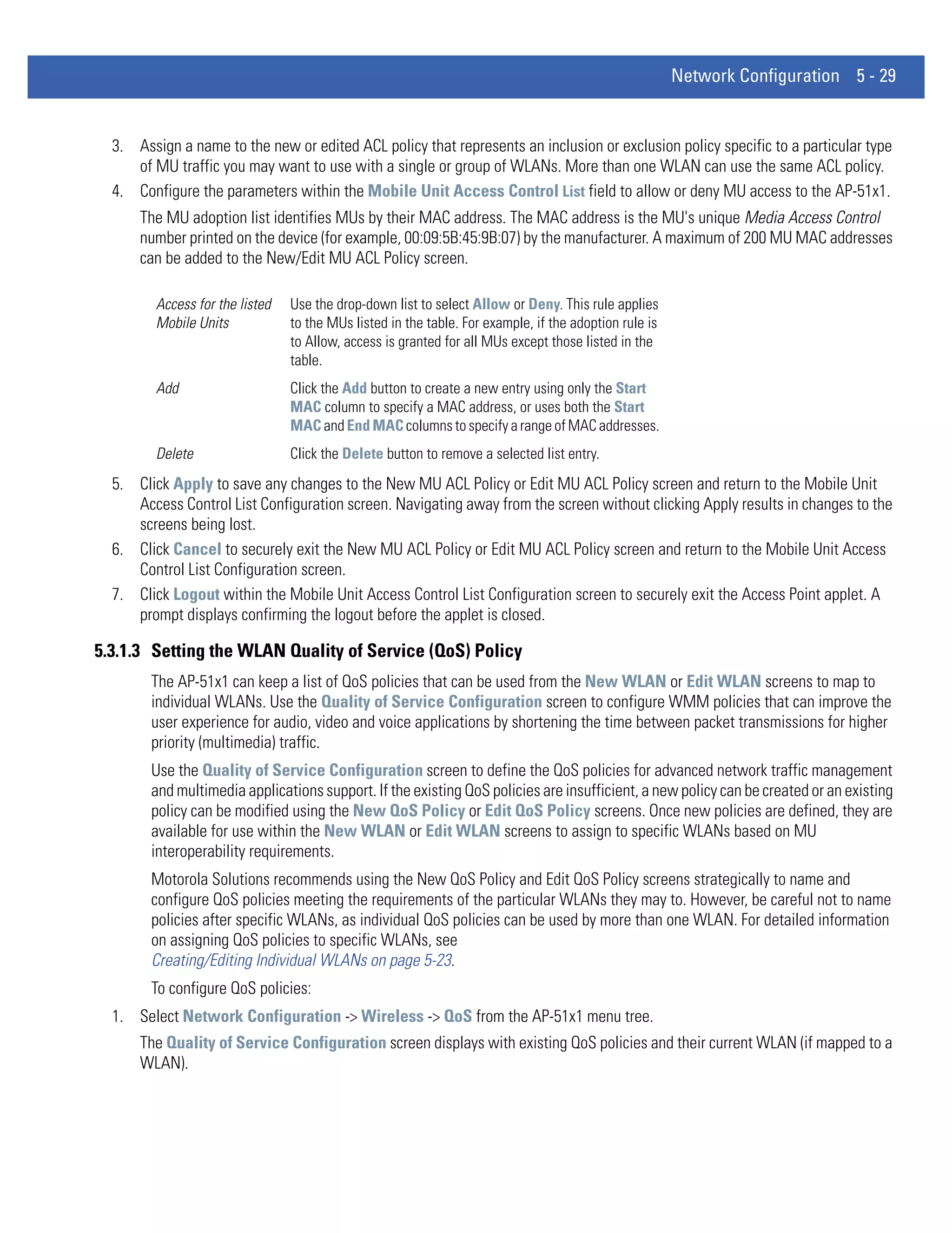
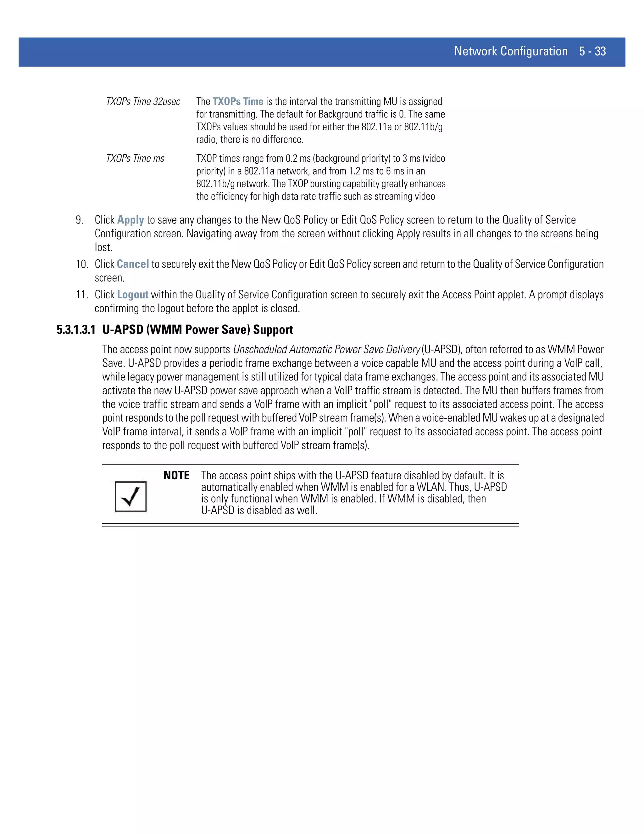
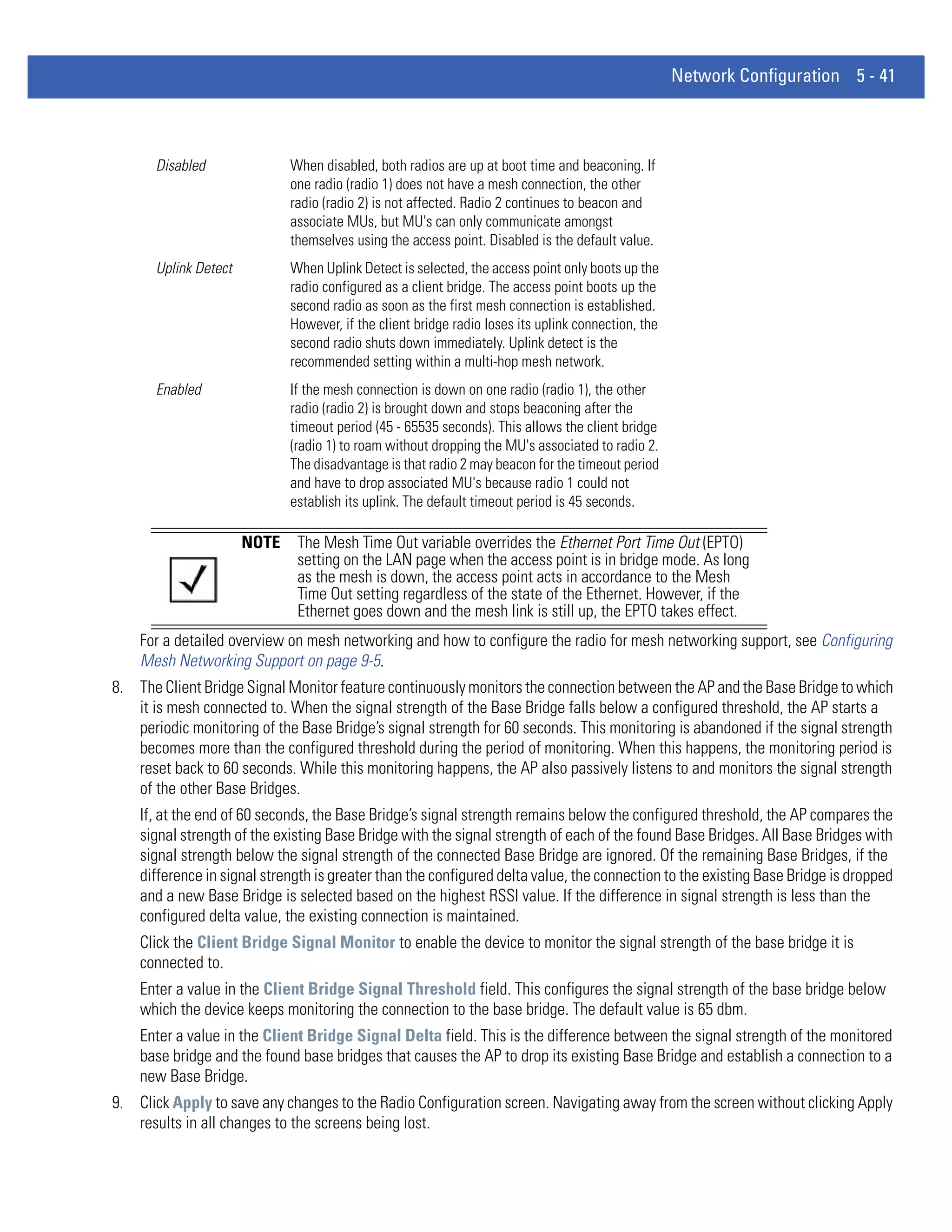
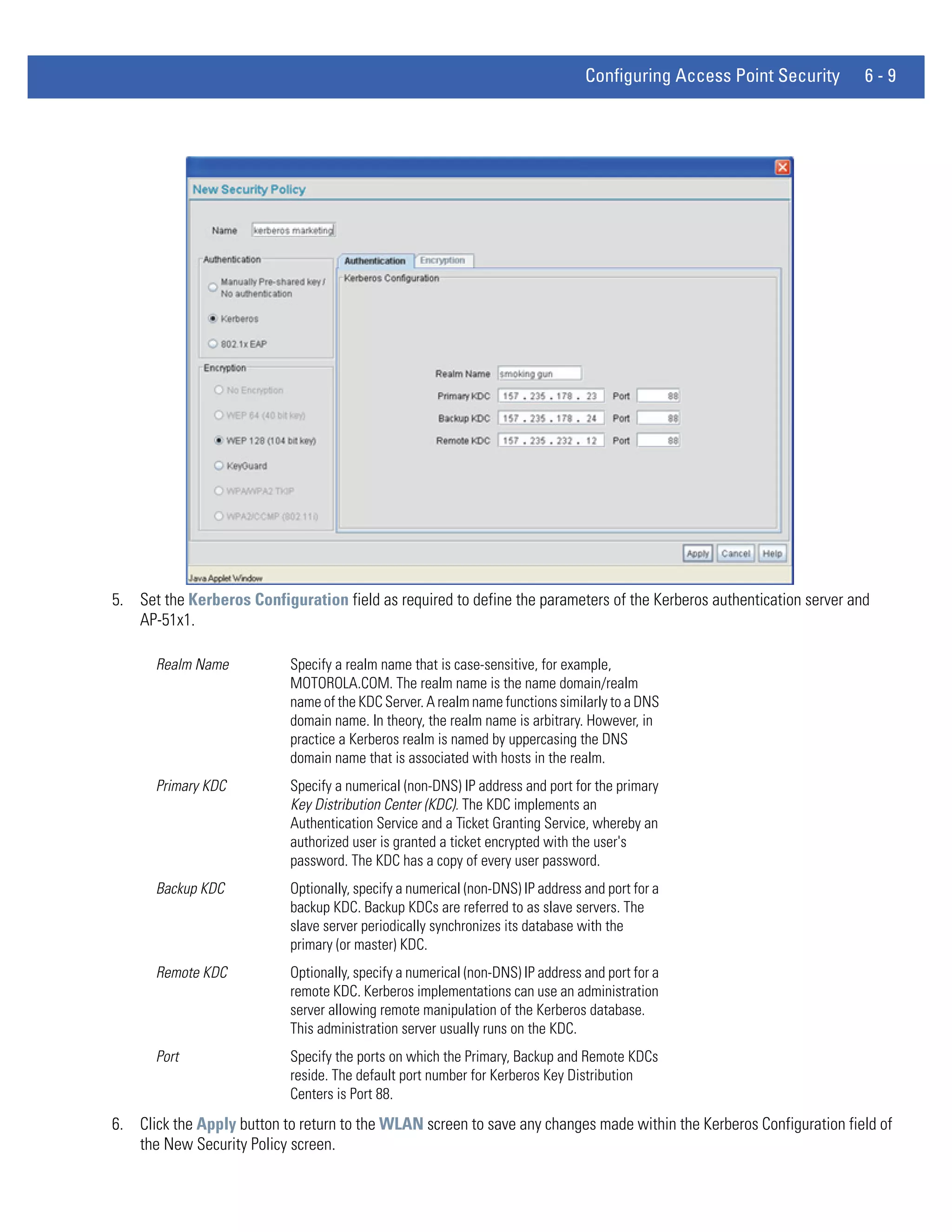
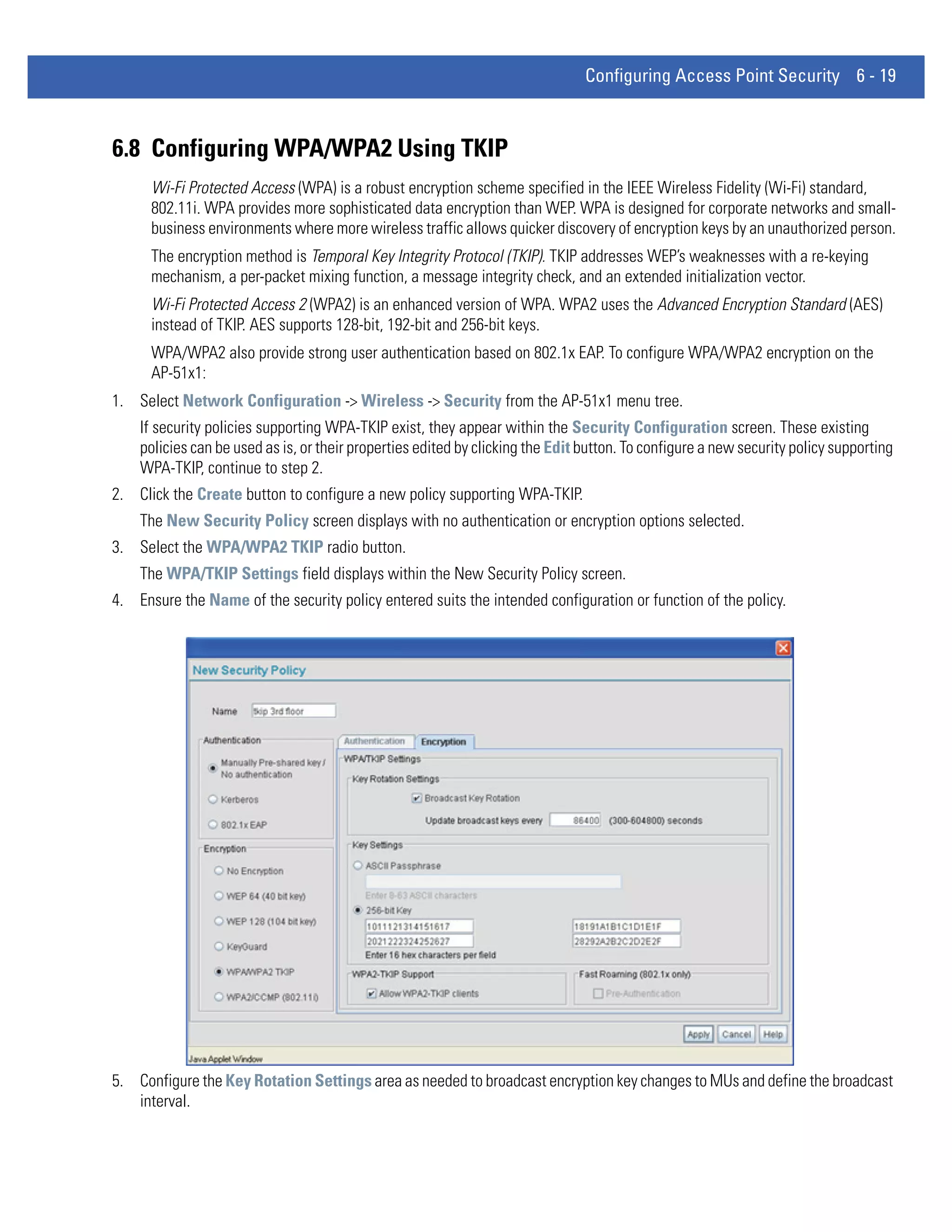
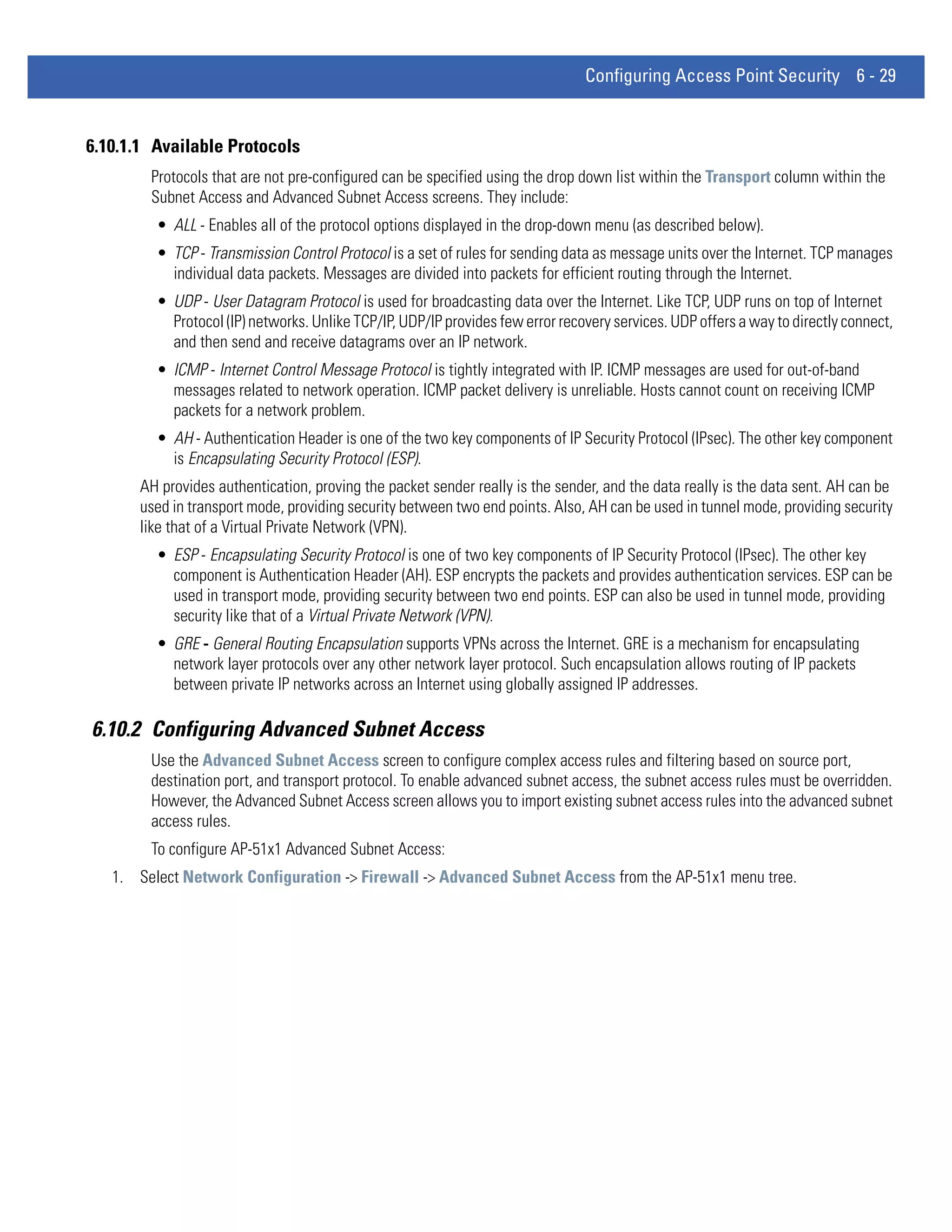
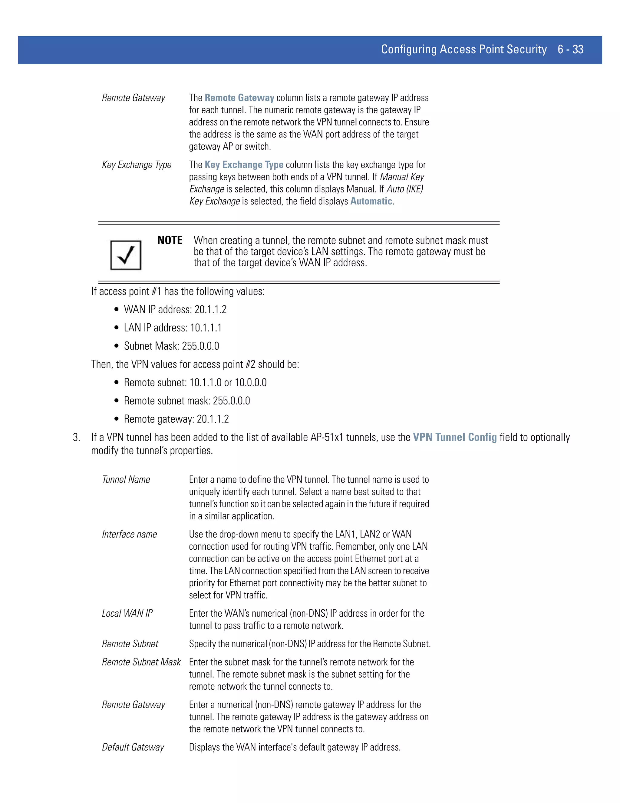
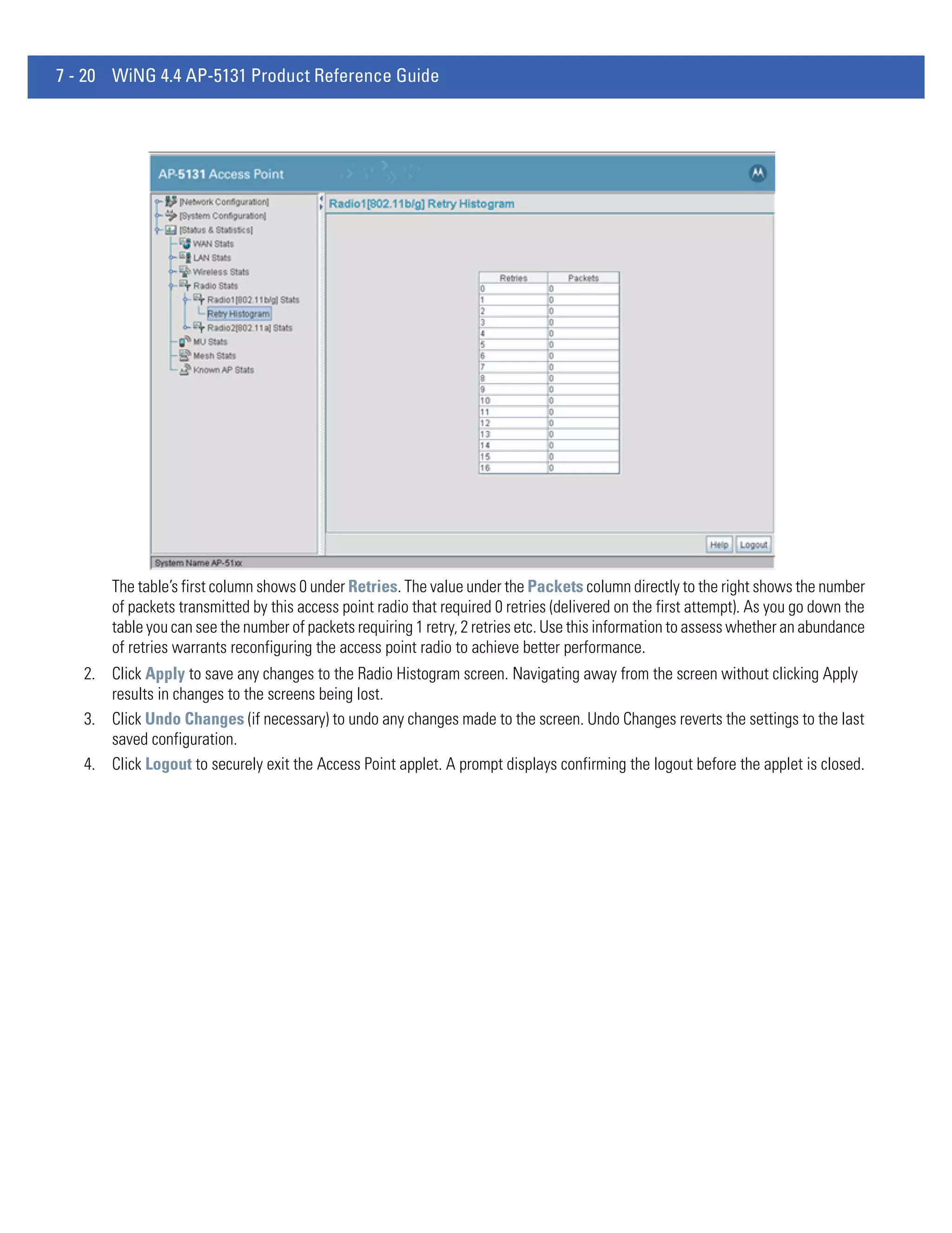
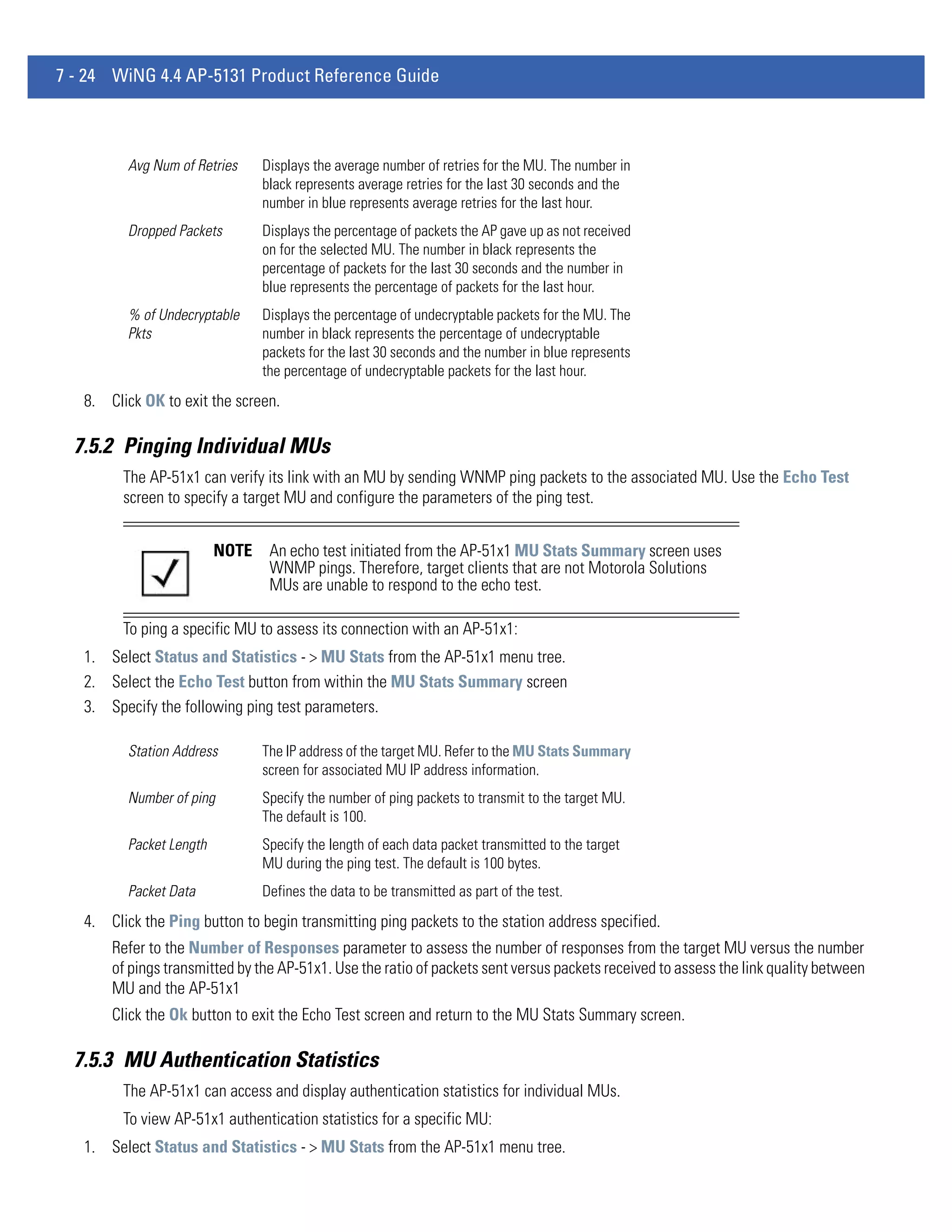
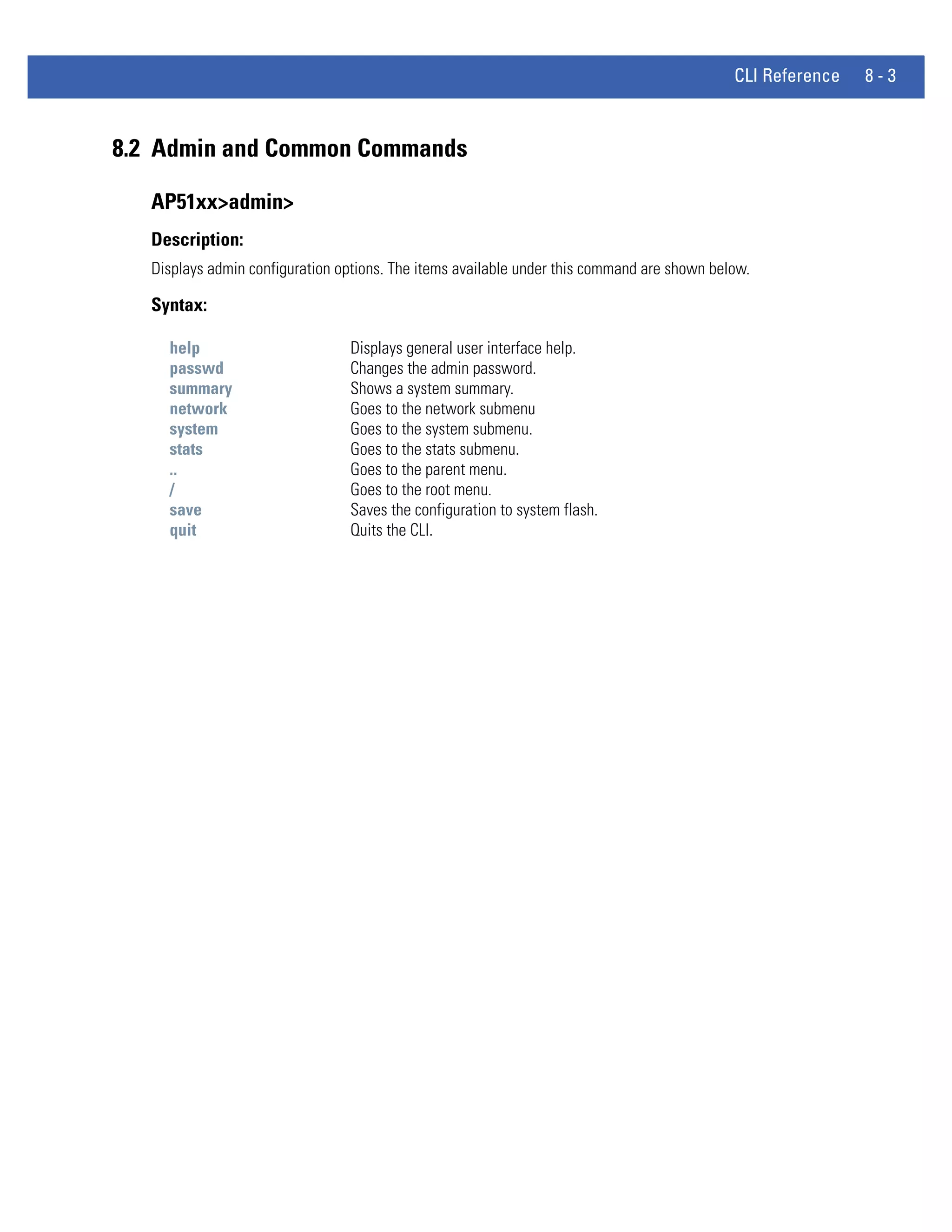
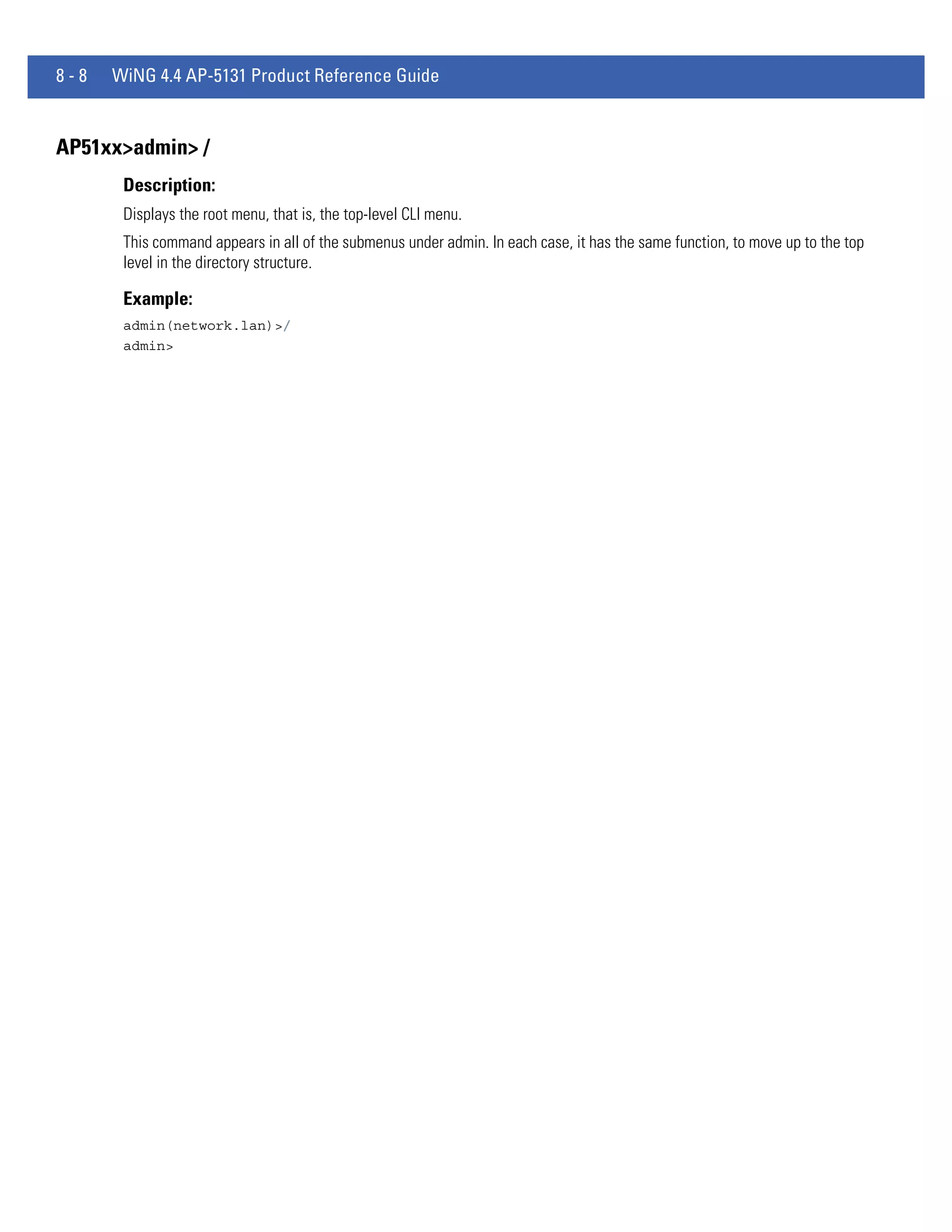
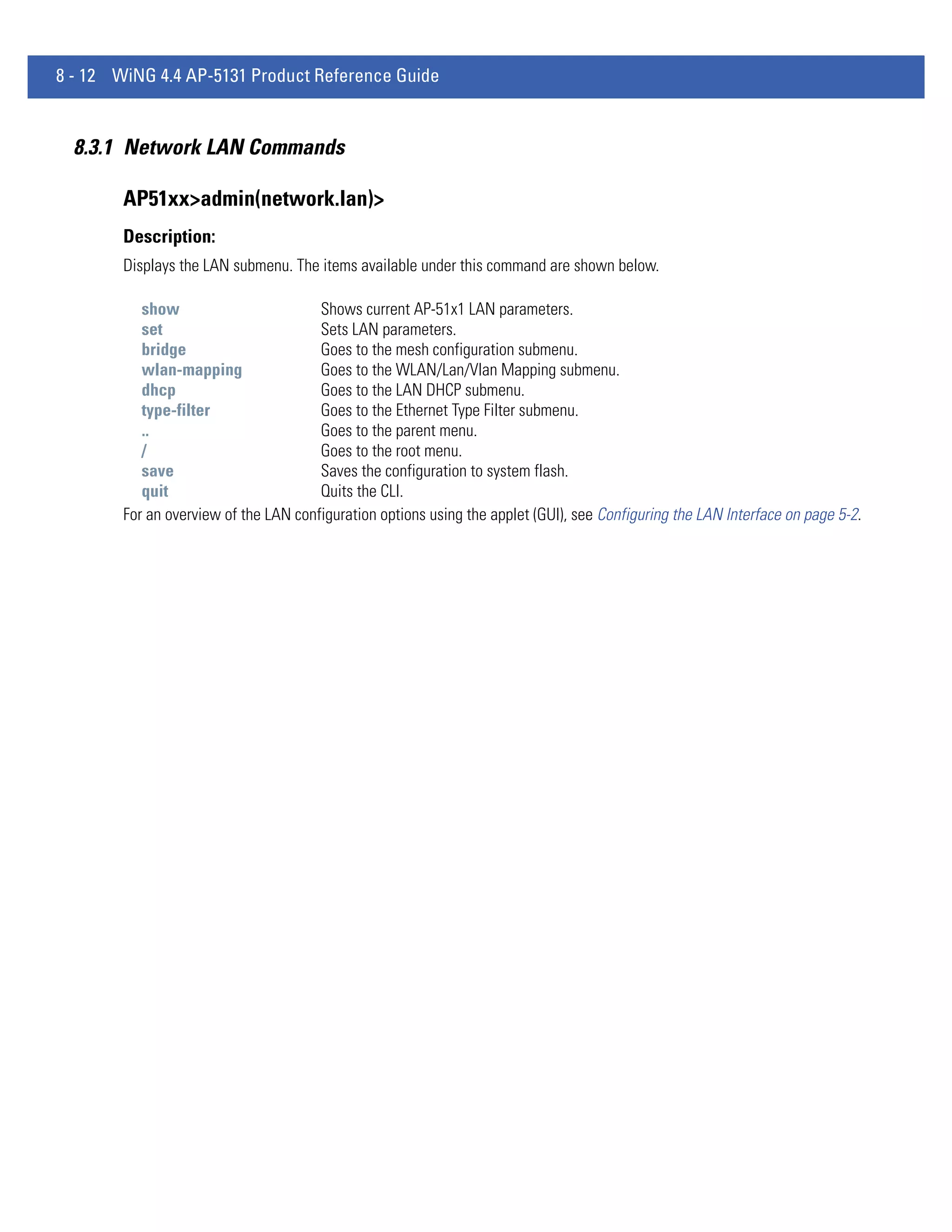
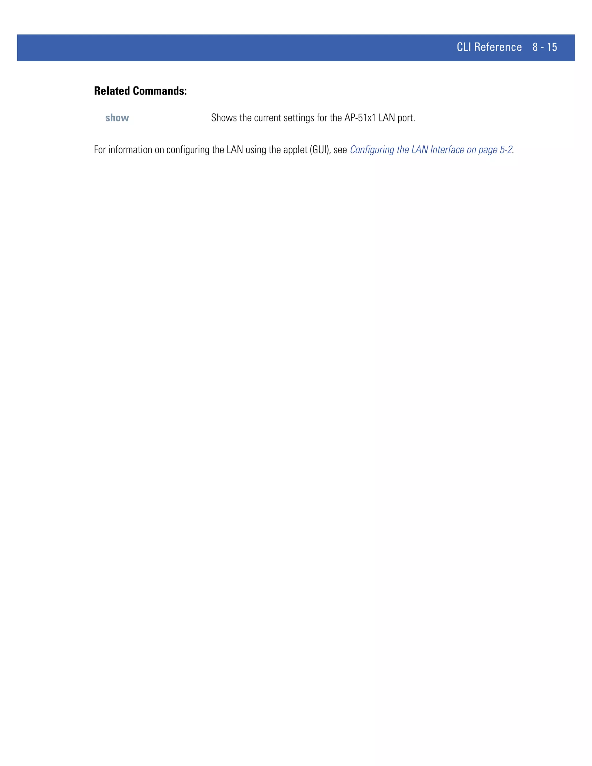
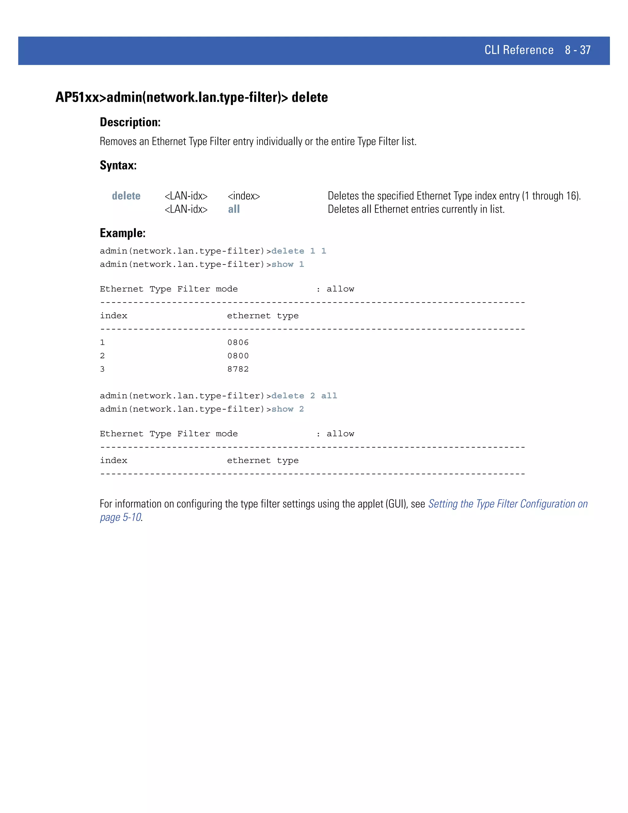
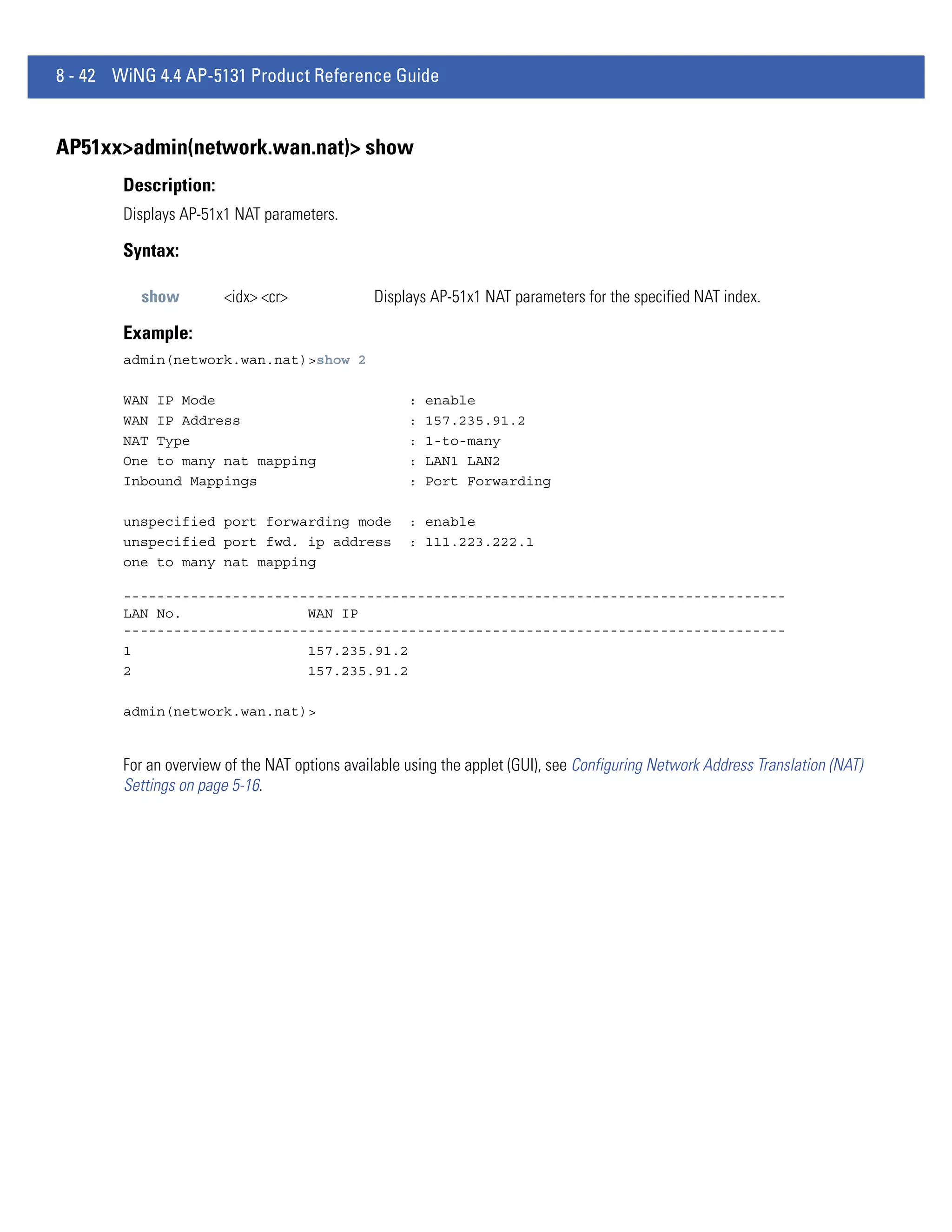
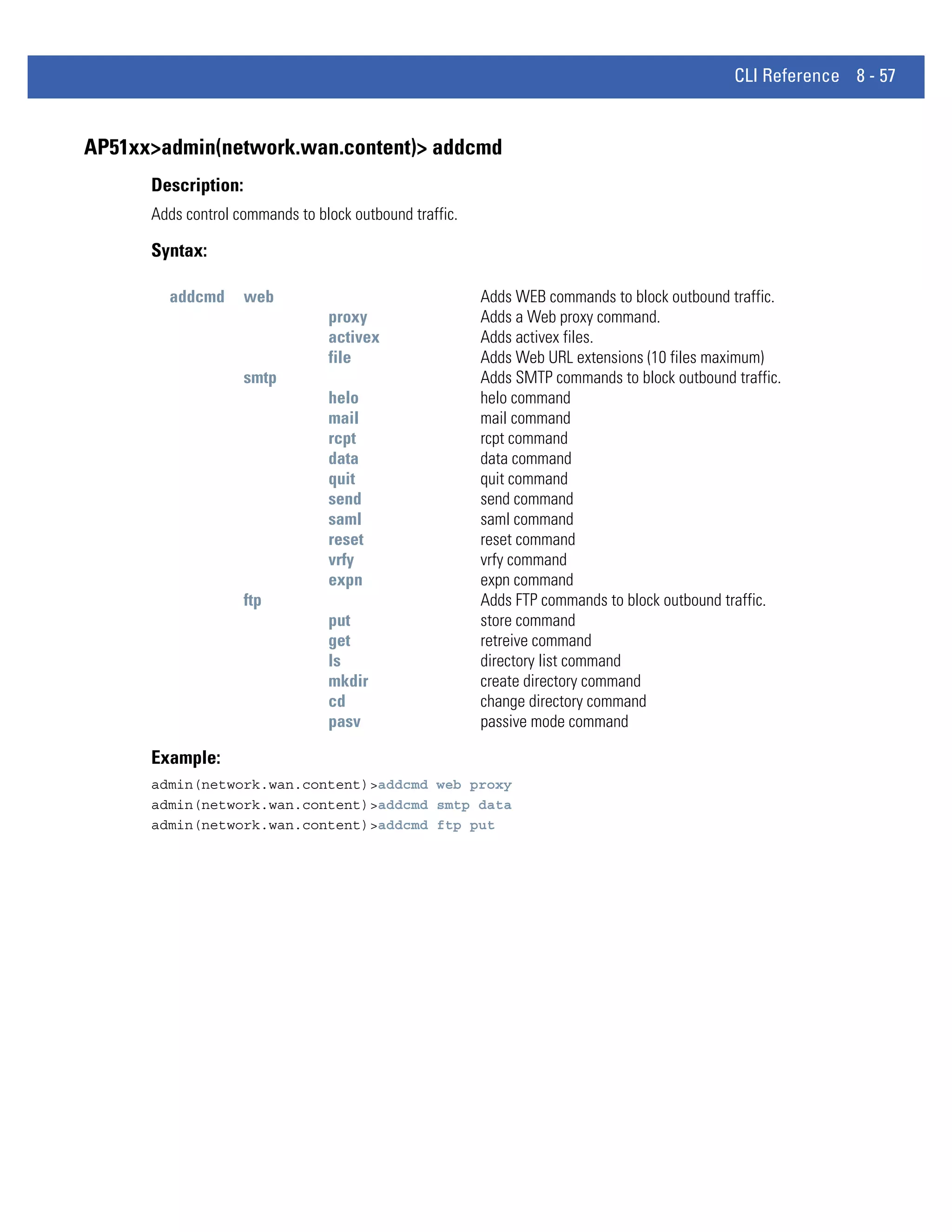
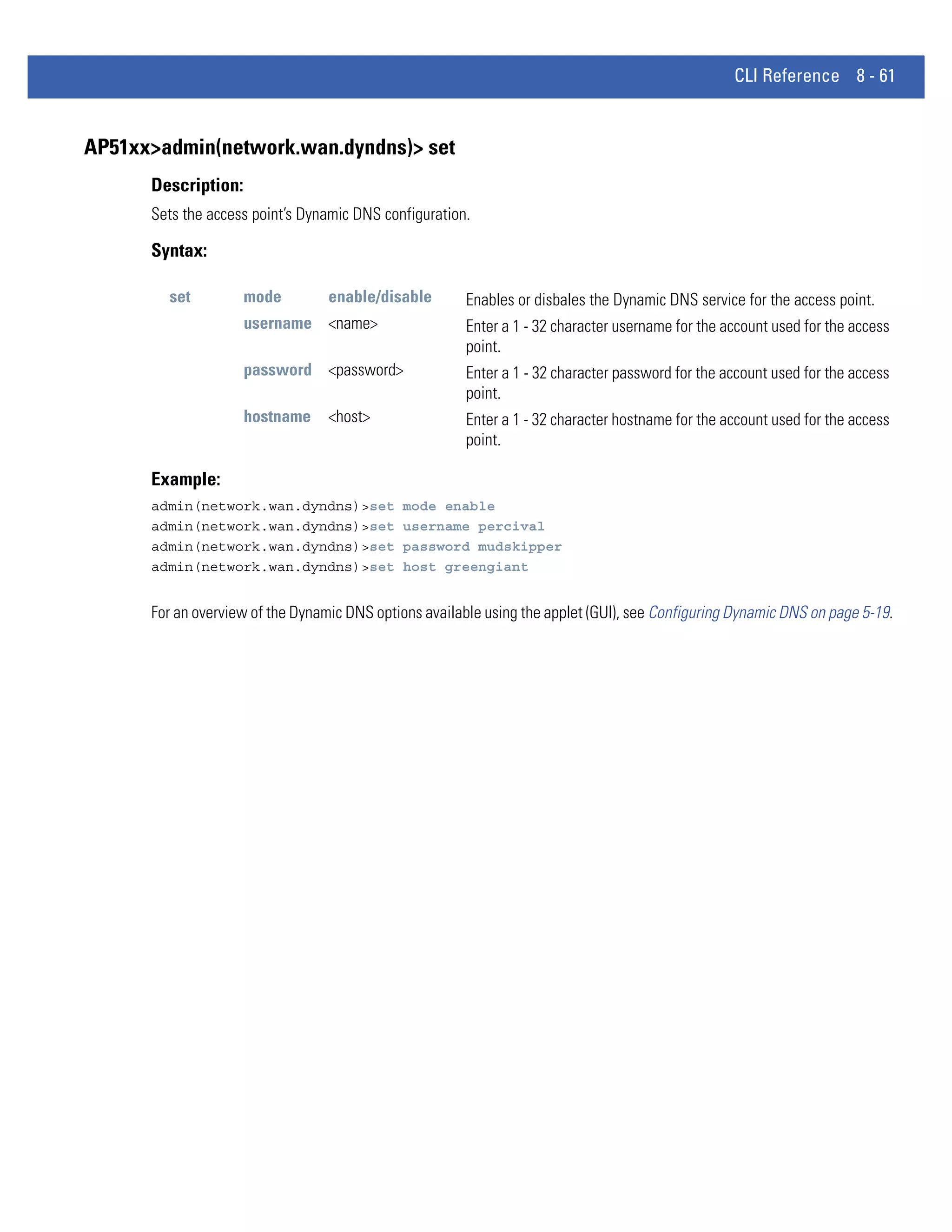
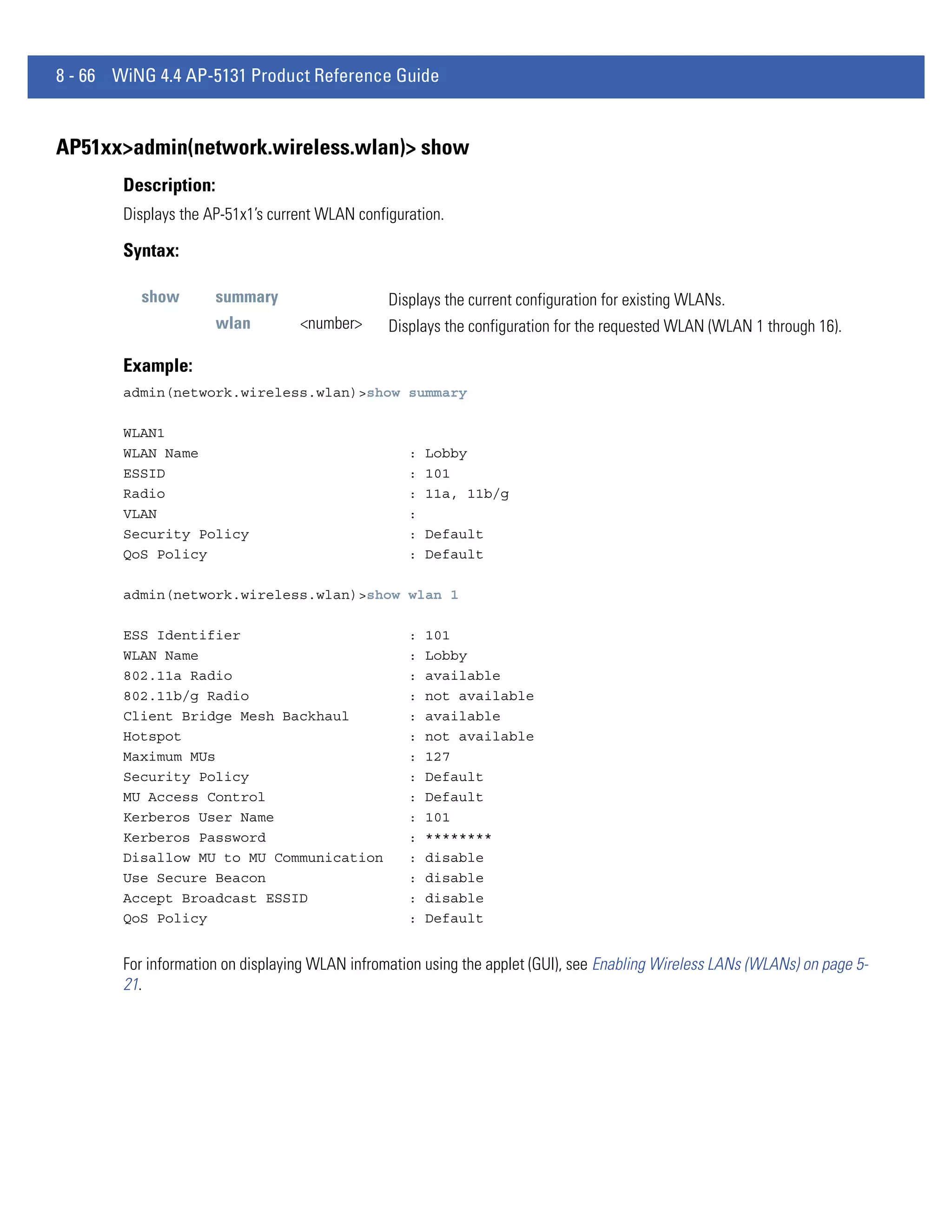
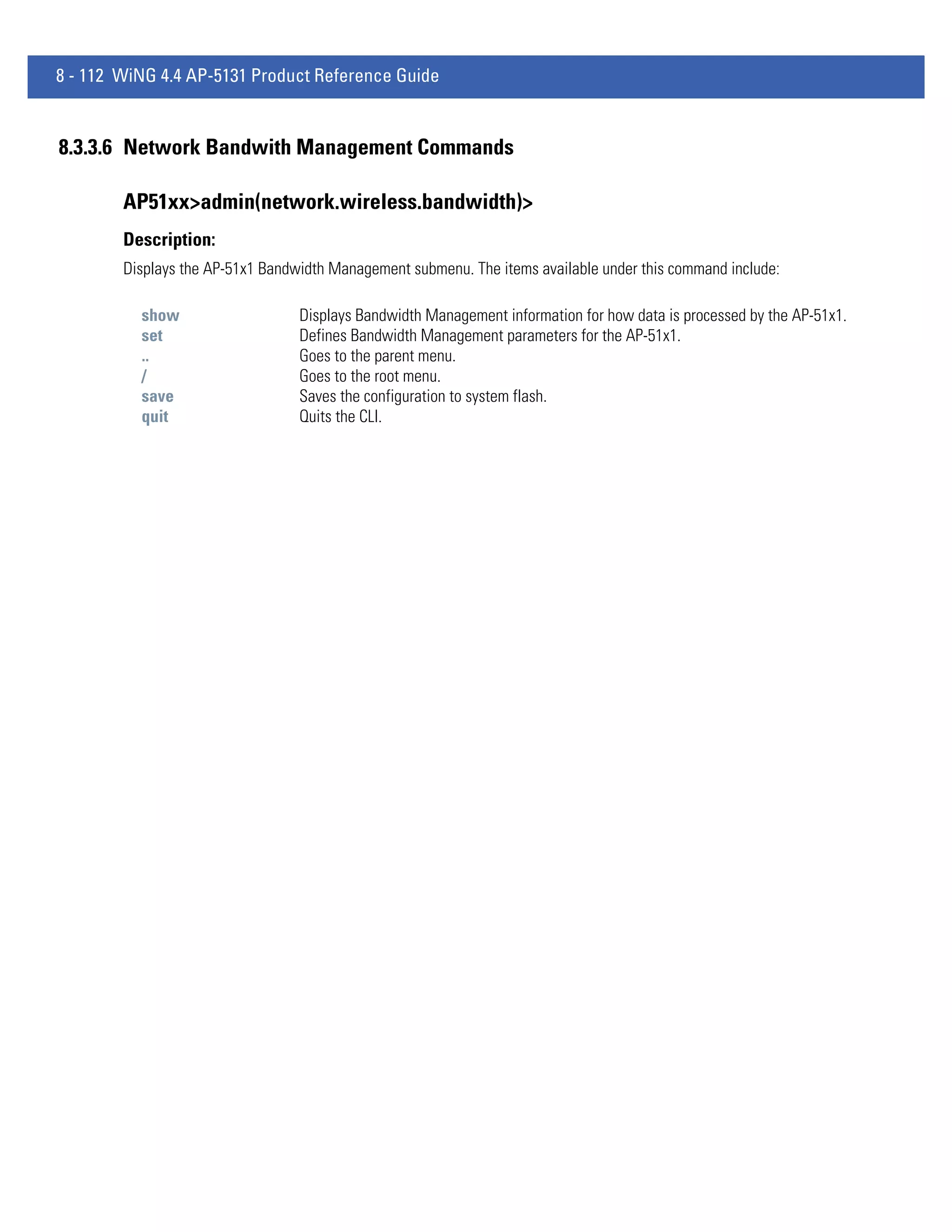
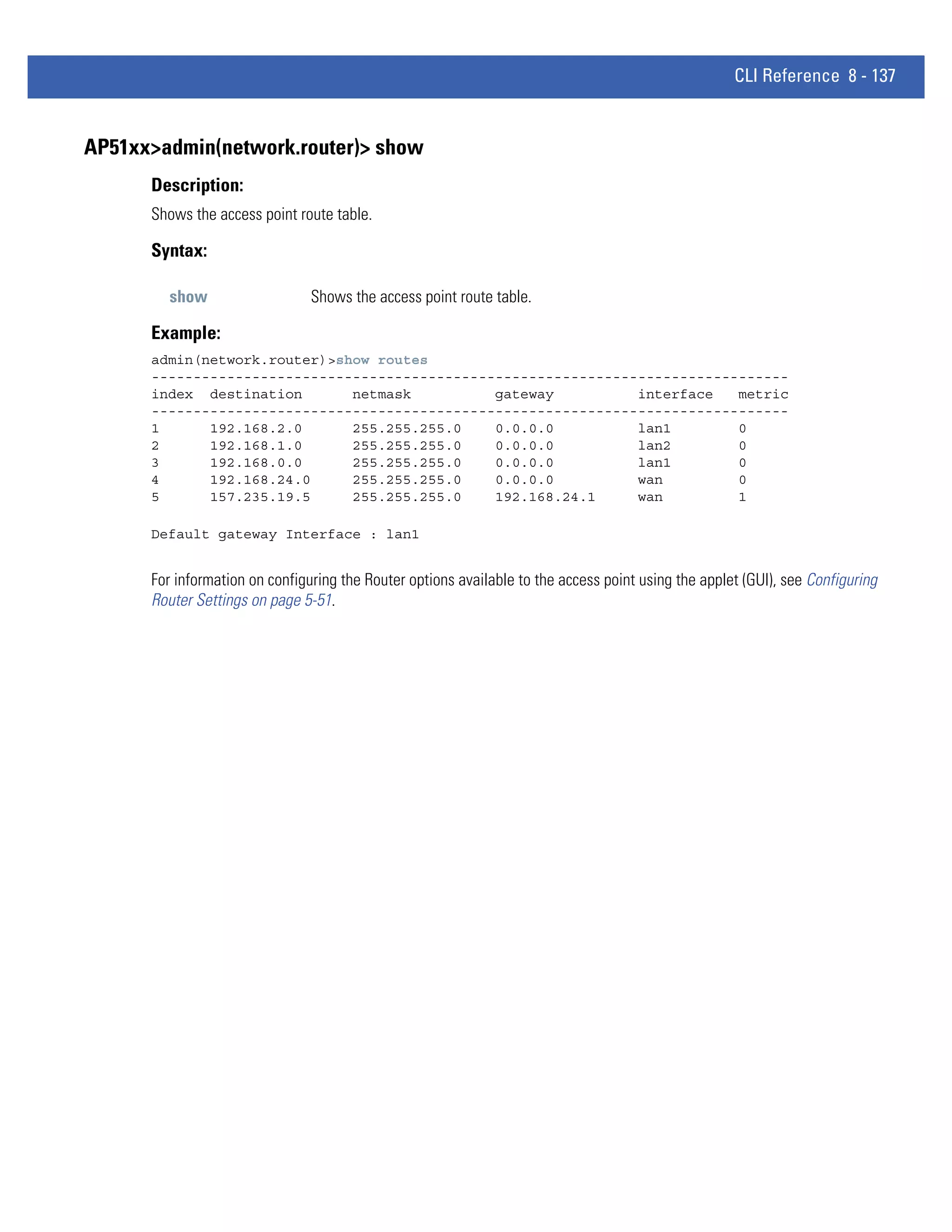
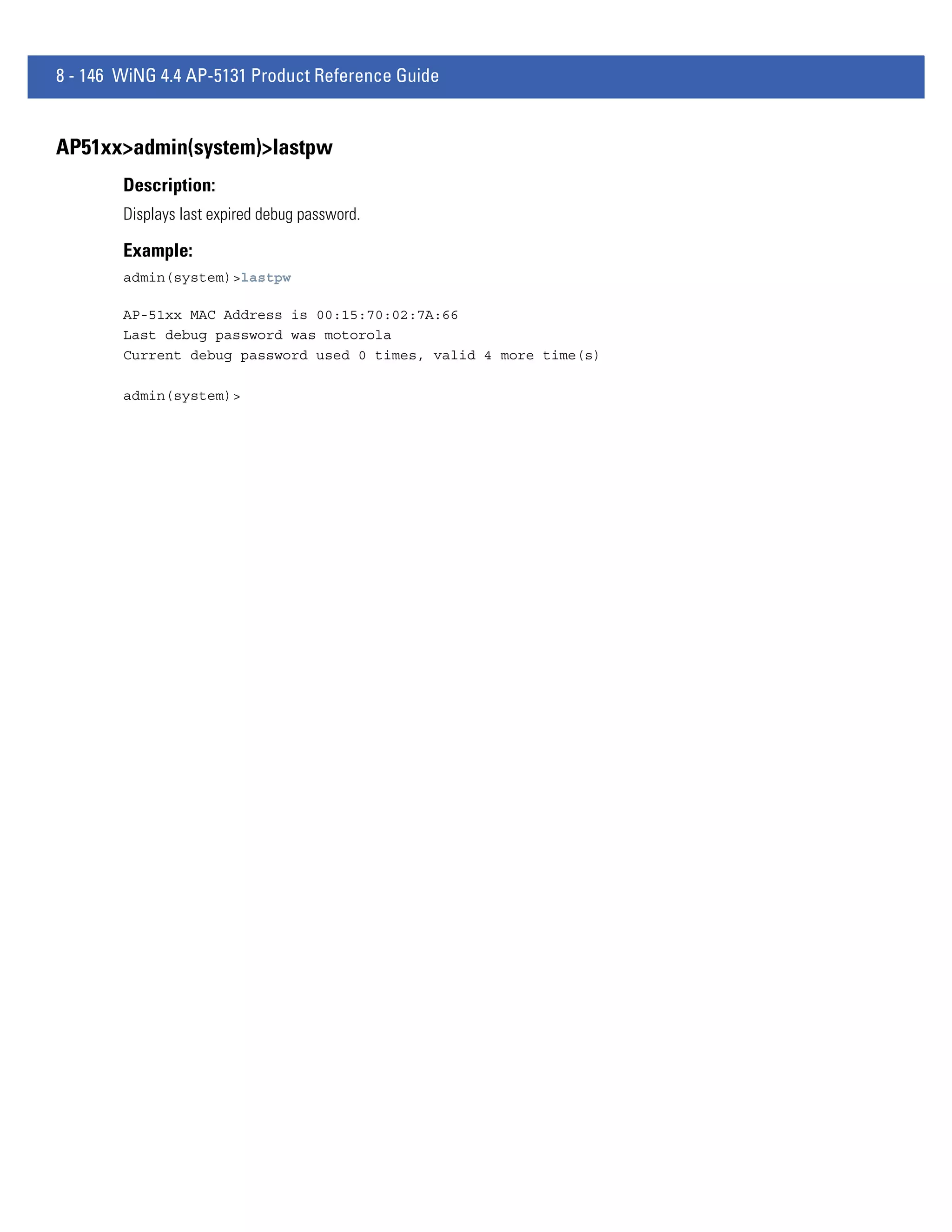
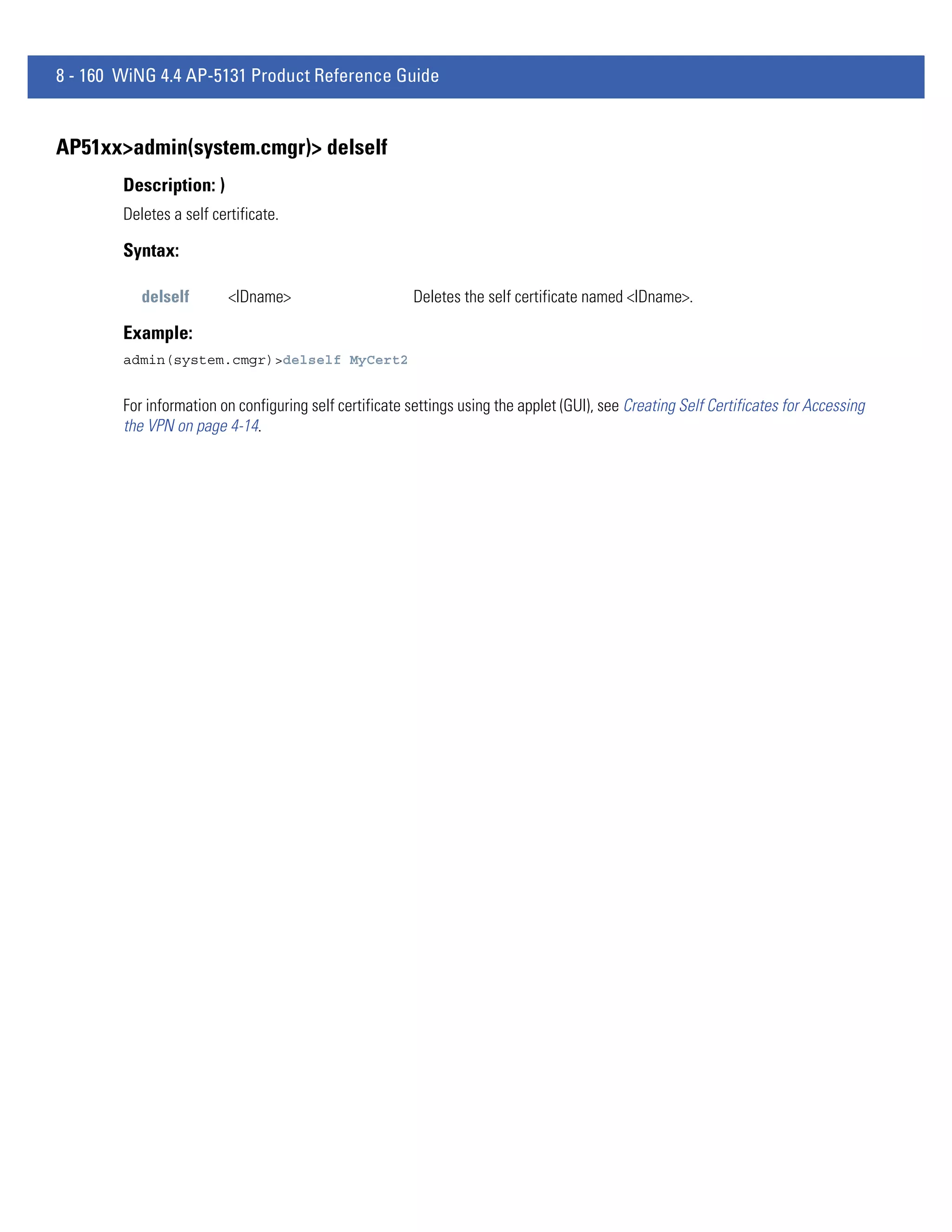
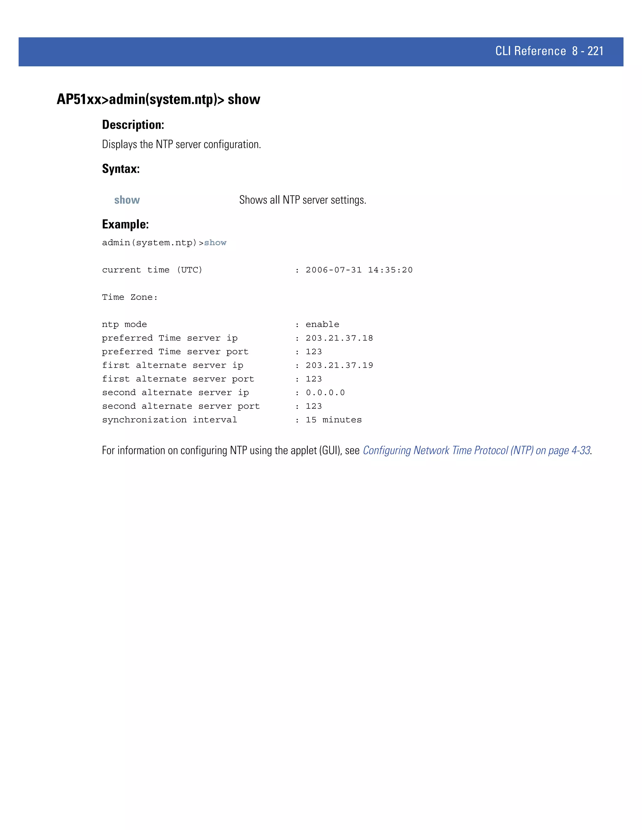
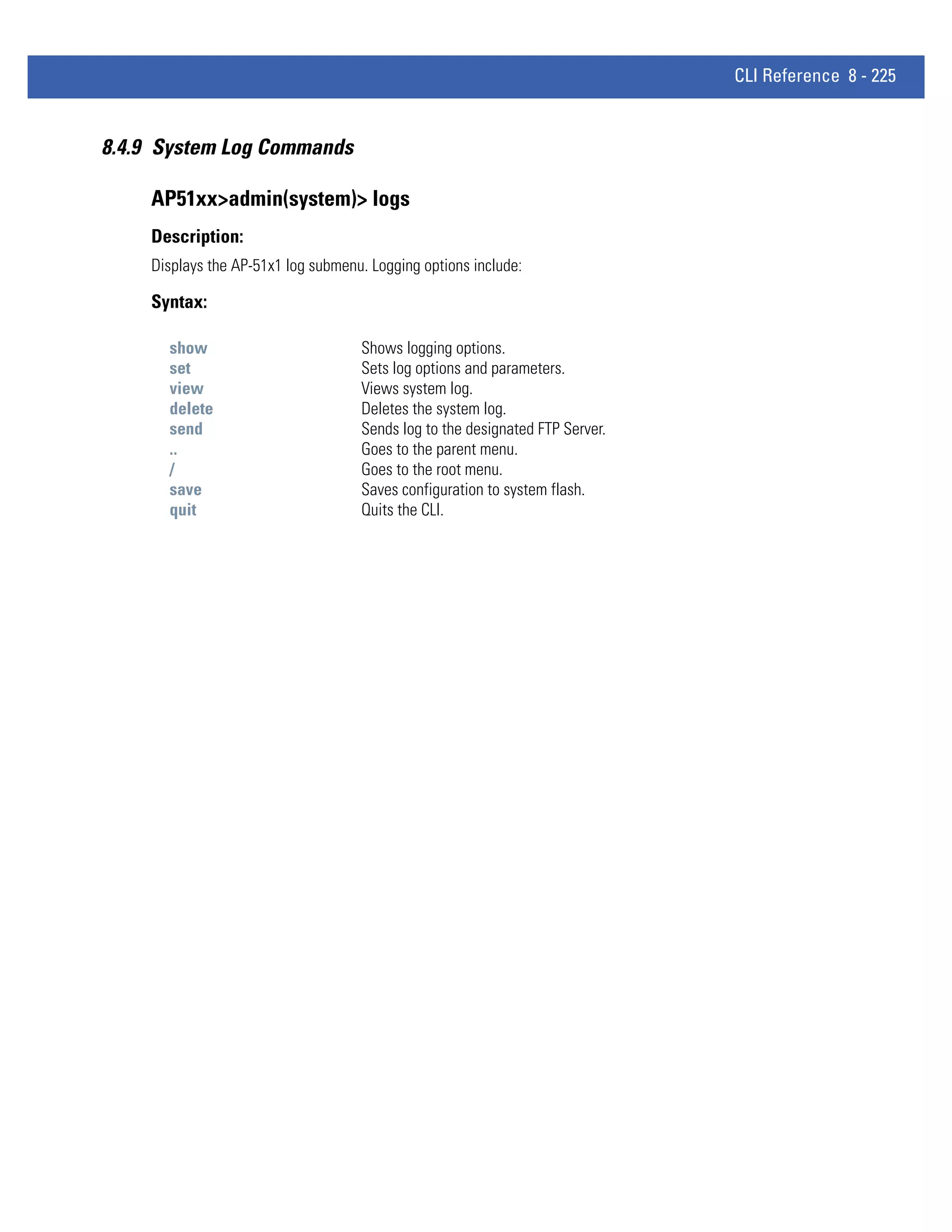
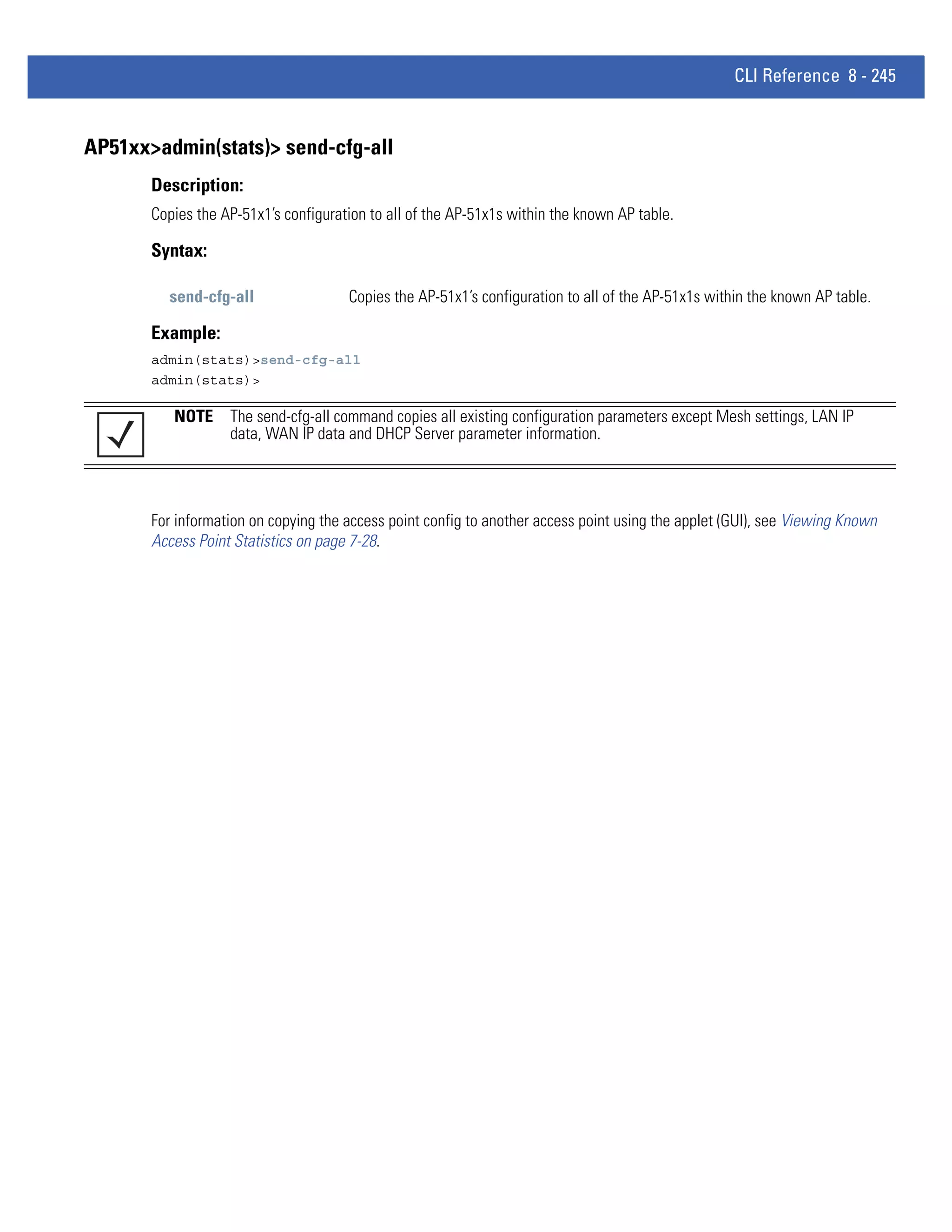
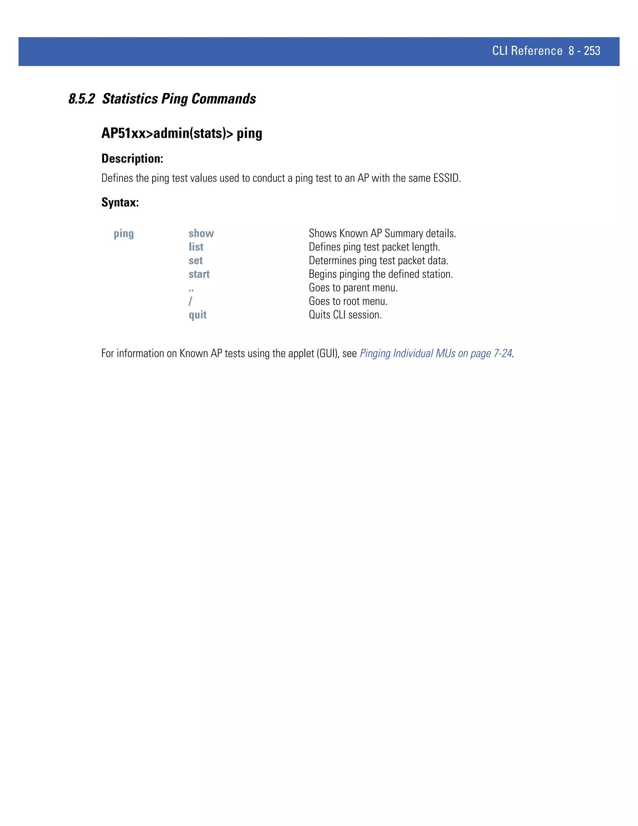
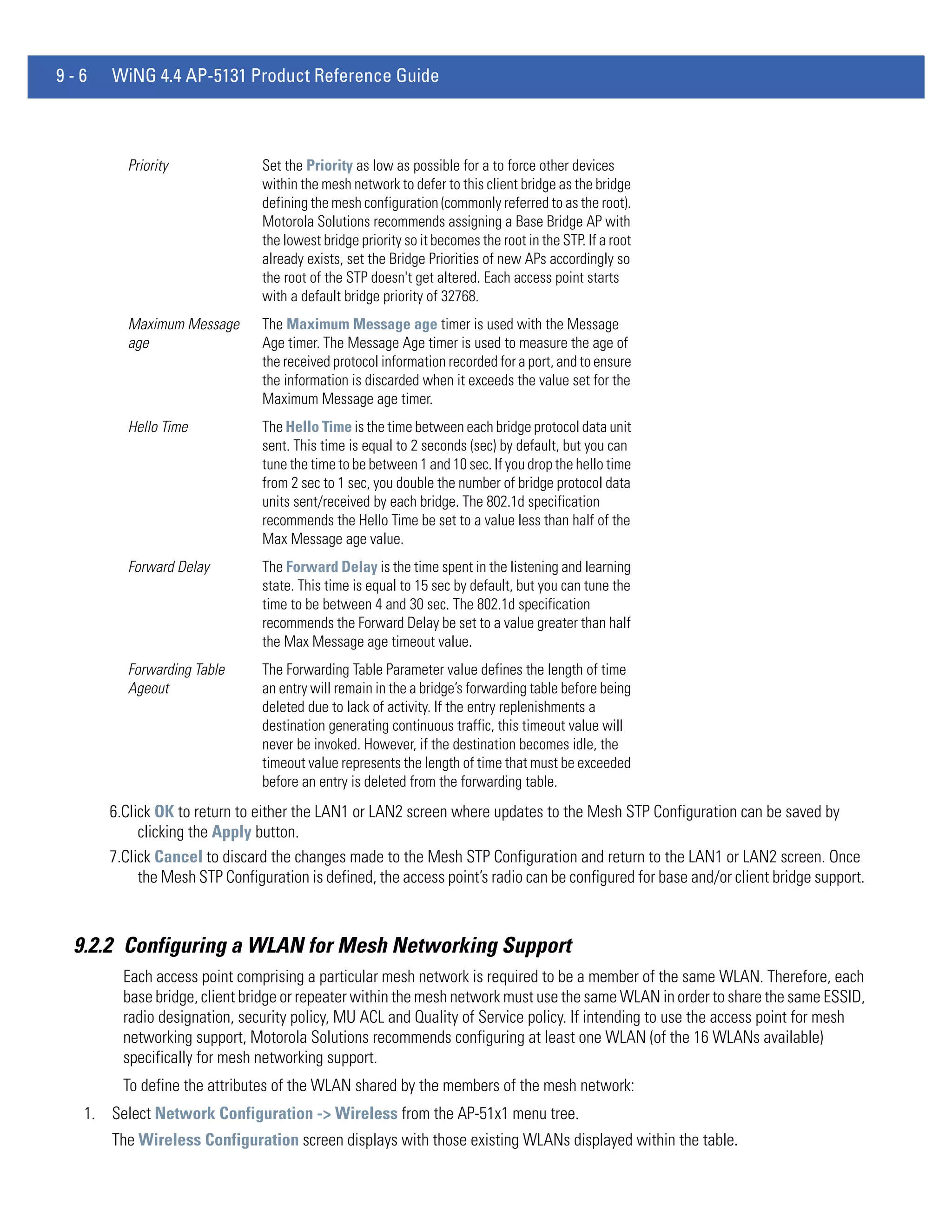
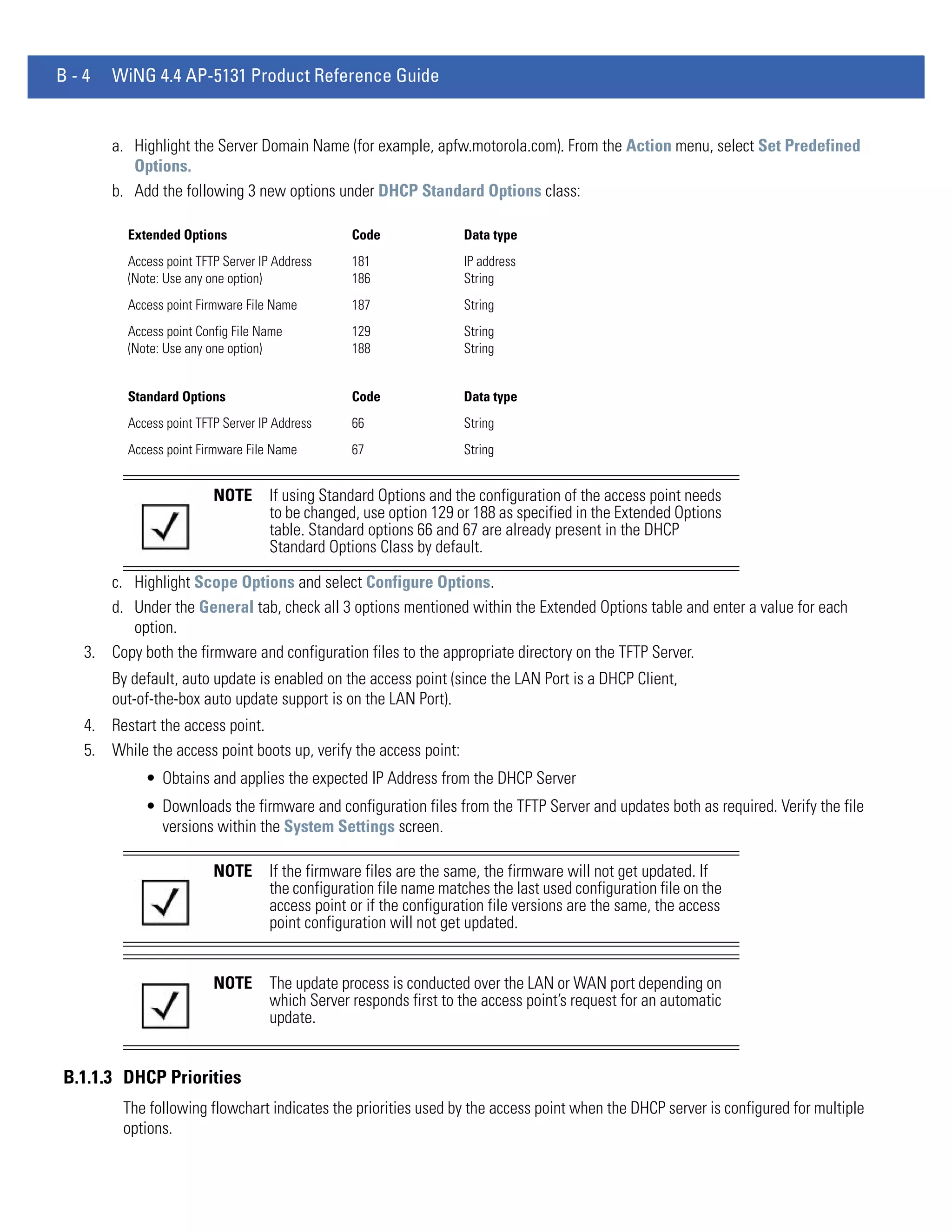
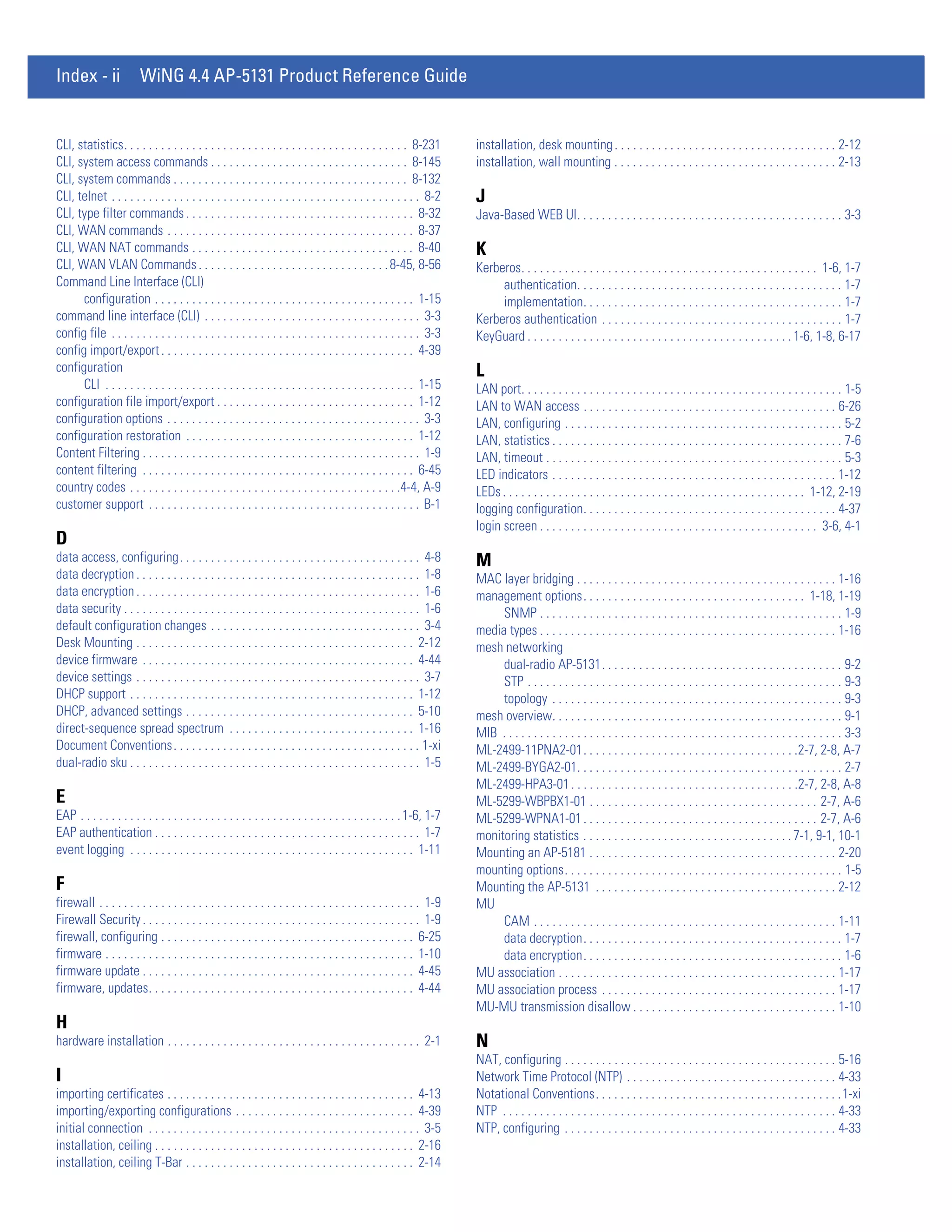
AP51xx>admin(system.logs)> send
Description:
Sends log and core file to an FTP Server.
Syntax:
send Sends the system log file via FTP to a location specified with the set command. Refer to the command
set under the AP51xx>admin(config) command for information on setting up an FTP server and login
information.
Example:
admin(system.logs)>send
File transfer : [ In progress ]
File transfer : [ Done ]
admin(system.logs)>
For information on configuring logging settings using the applet (GUI), see Logging Configuration on page 4-37.](https://image.slidesharecdn.com/motorolasolutionswing4-4ap51xxaccesspointproductreferenceguidepartno-72e-157066-01rev-a-120807142110-phpapp02/75/Motorola-solutions-wing-4-4-ap51xx-access-point-product-reference-guide-part-no-72-e-157066-01-rev-a-500-2048.jpg)
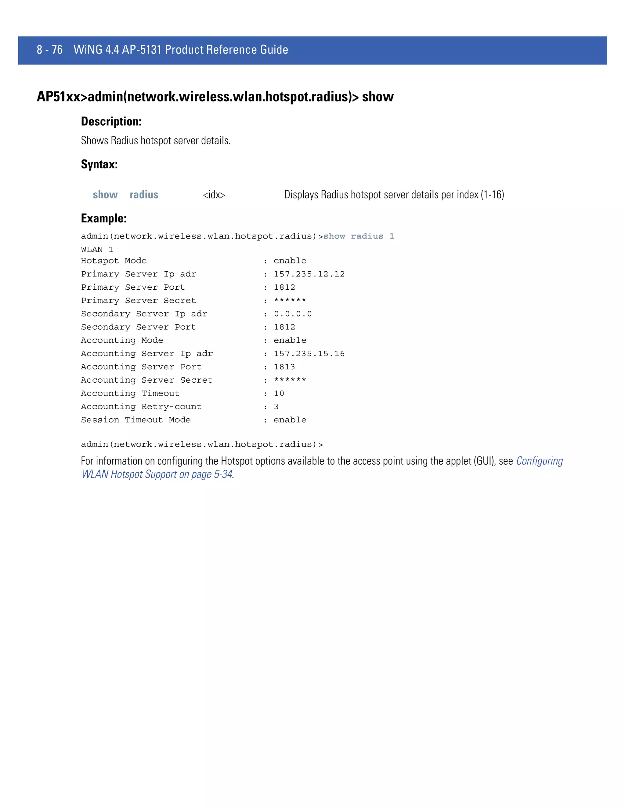
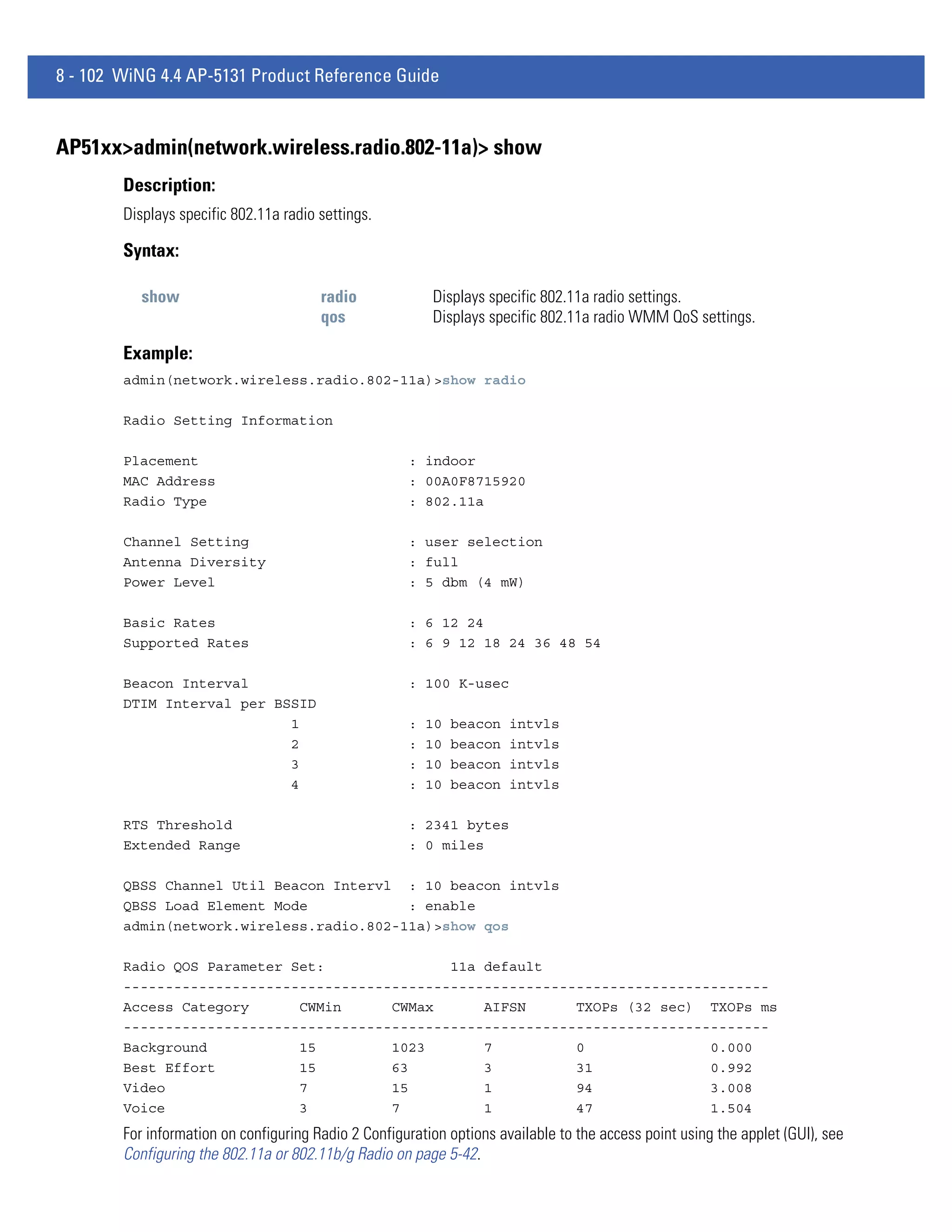
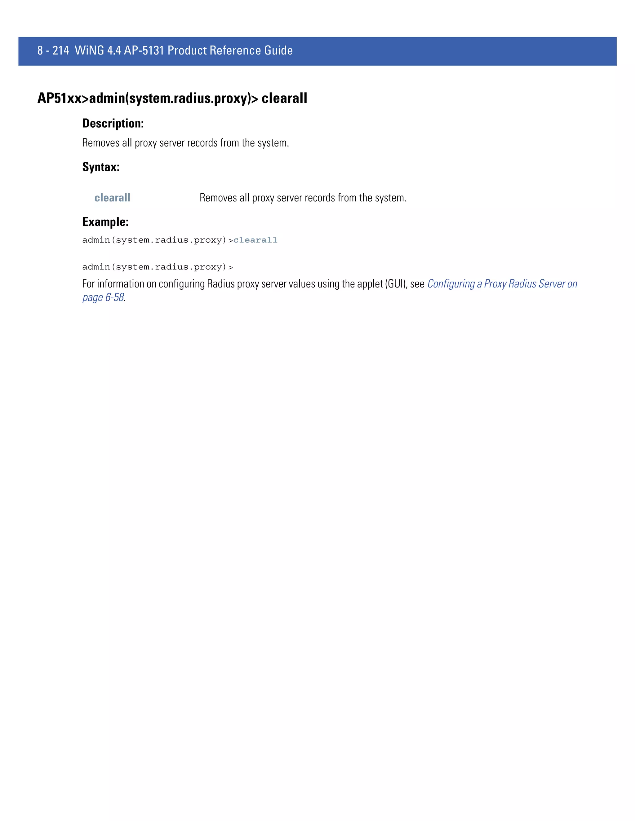
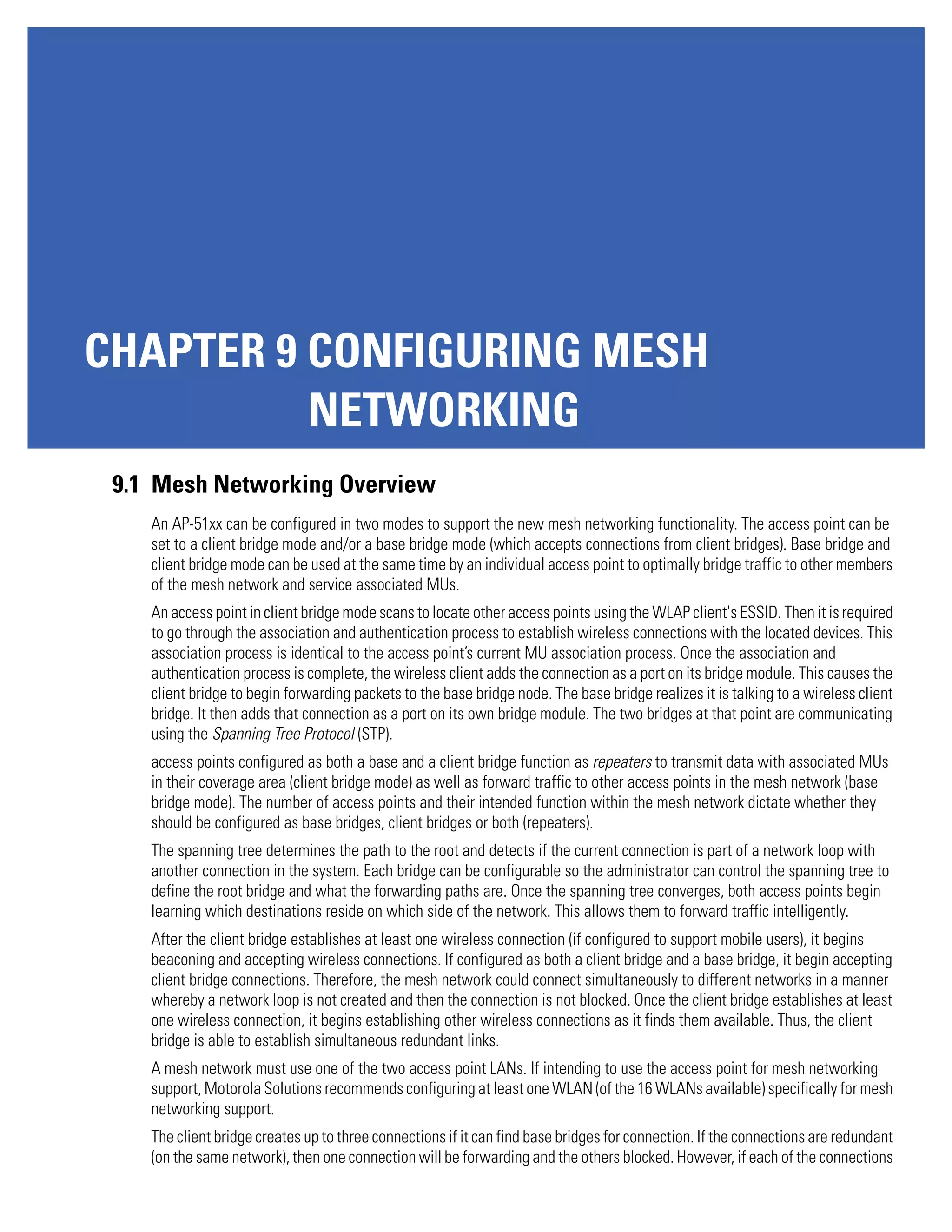
![8 - 236 WiNG 4.4 AP-5131 Product Reference Guide
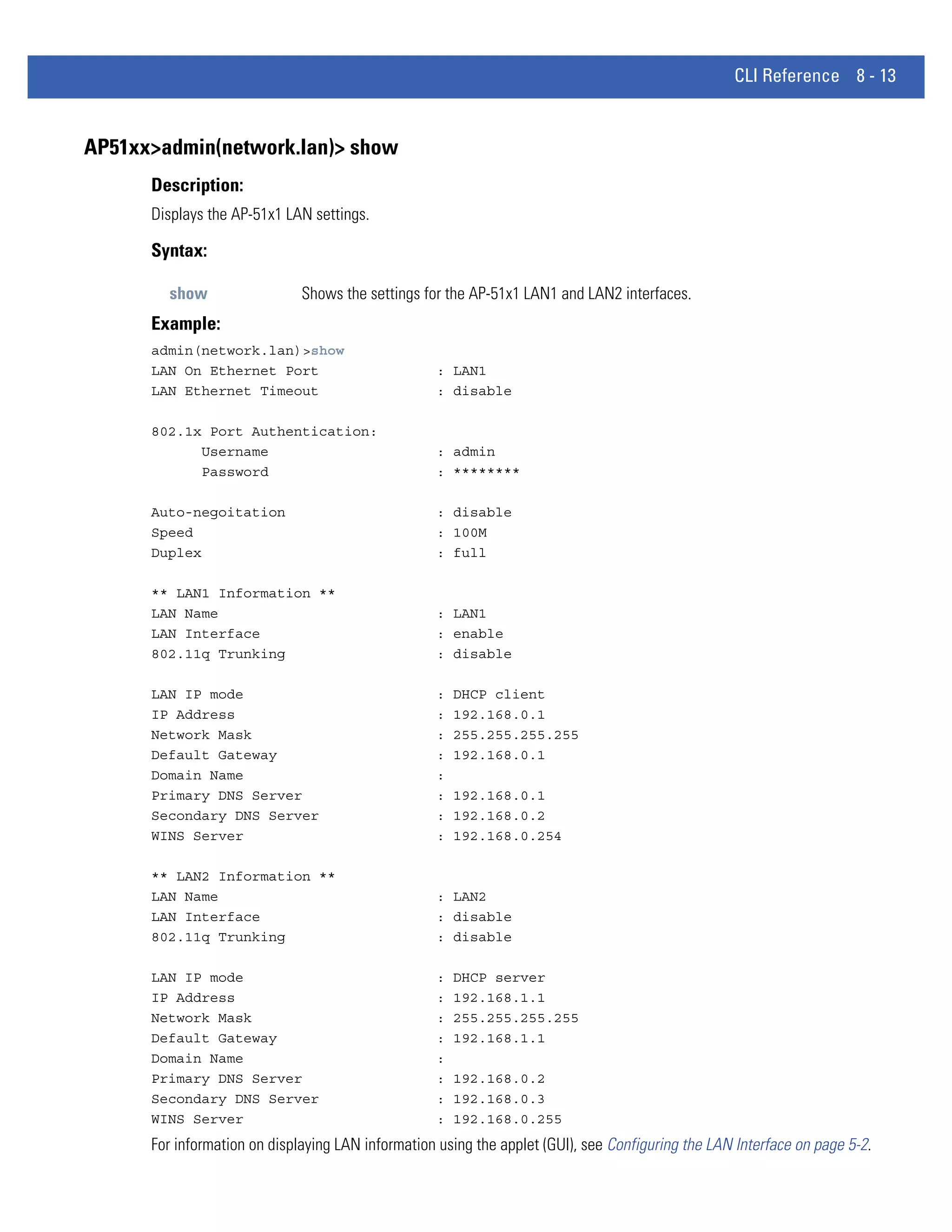
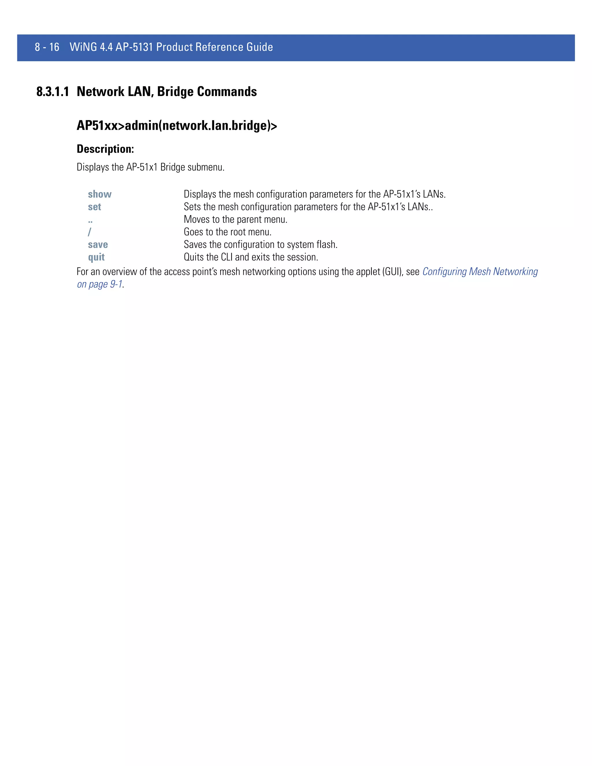
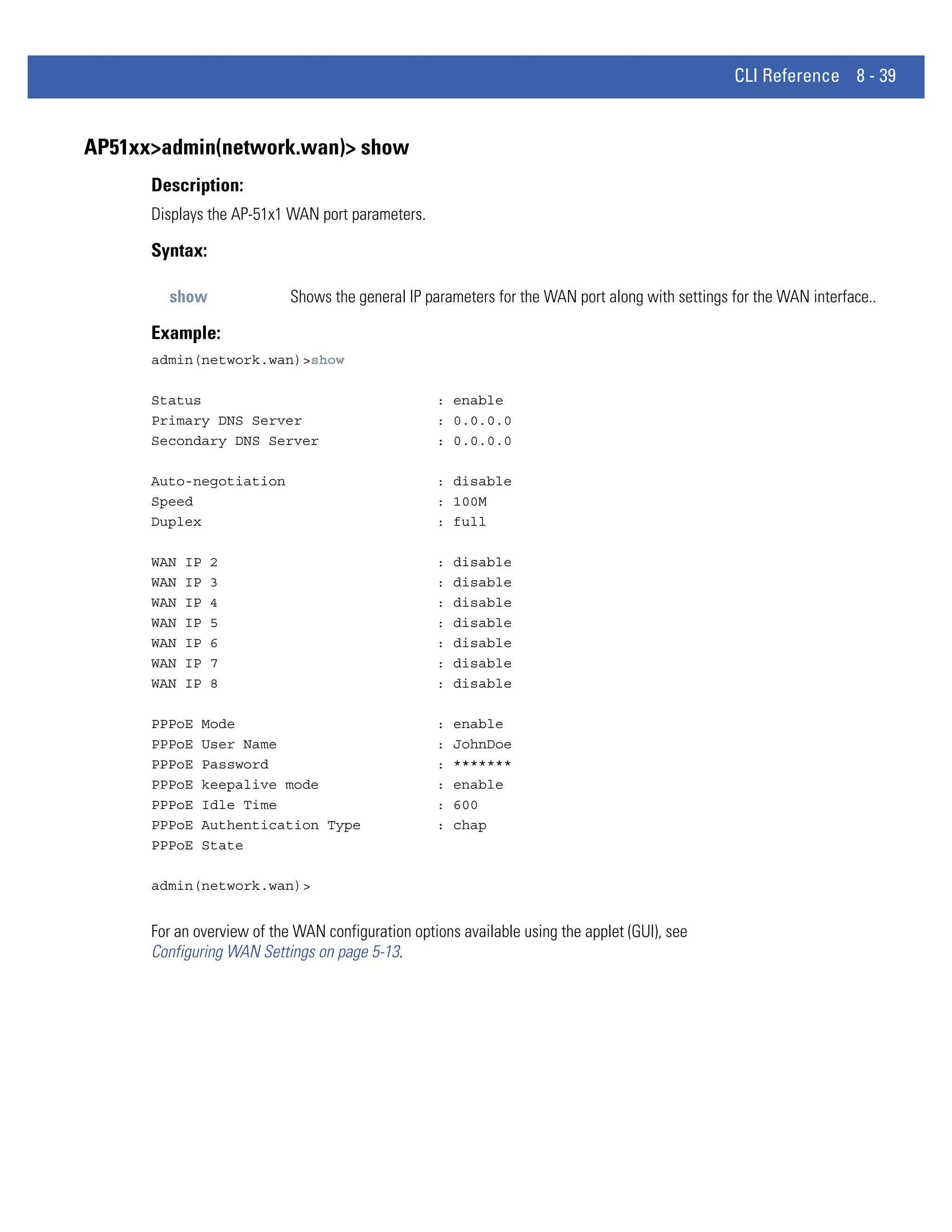
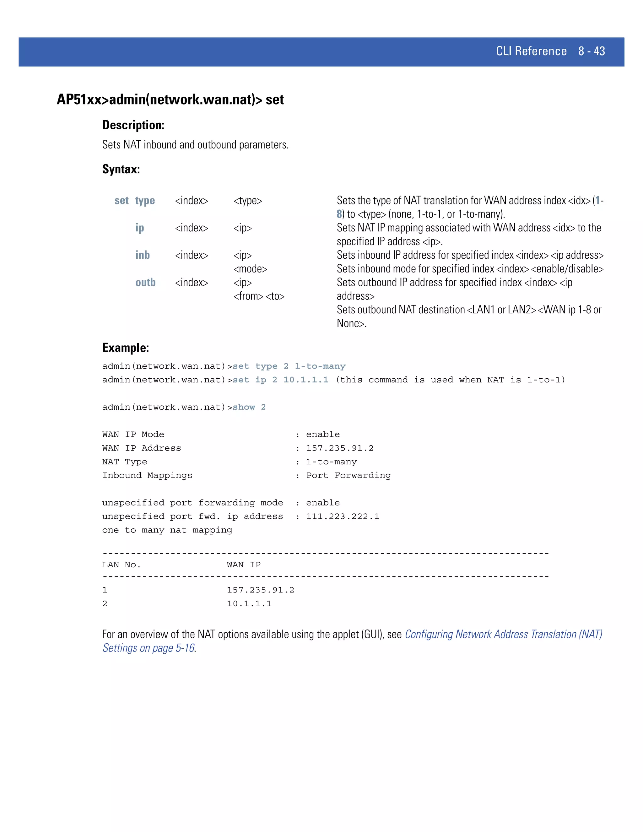
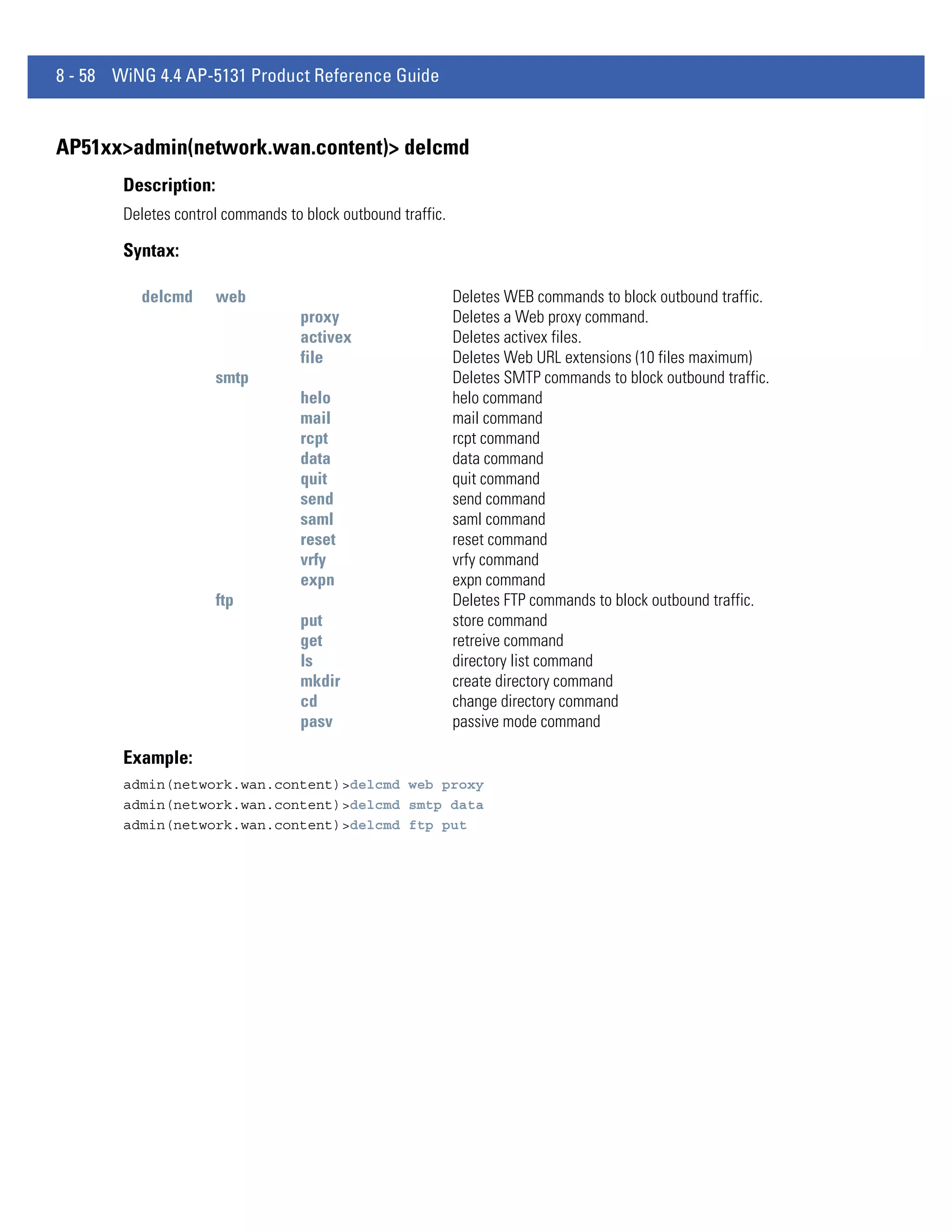
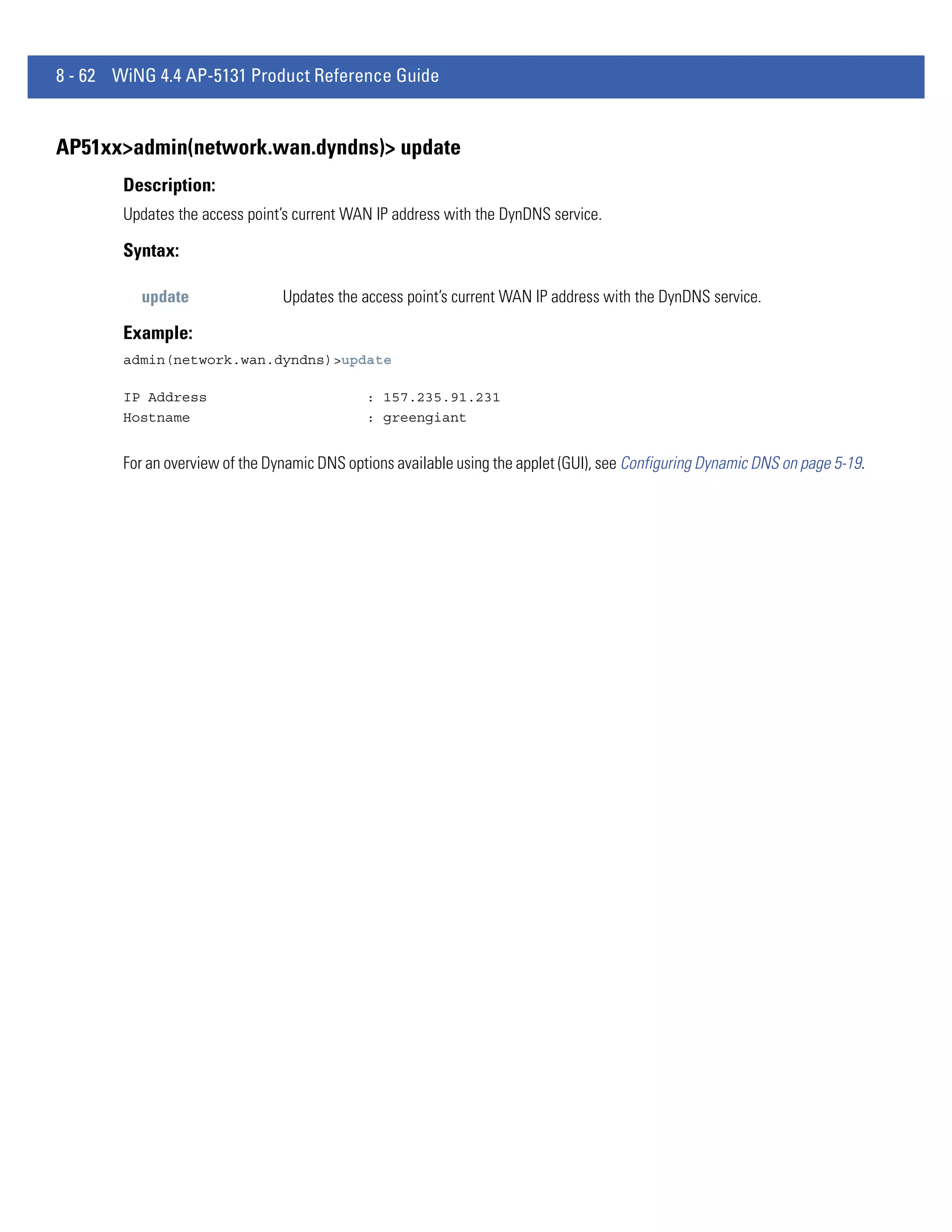
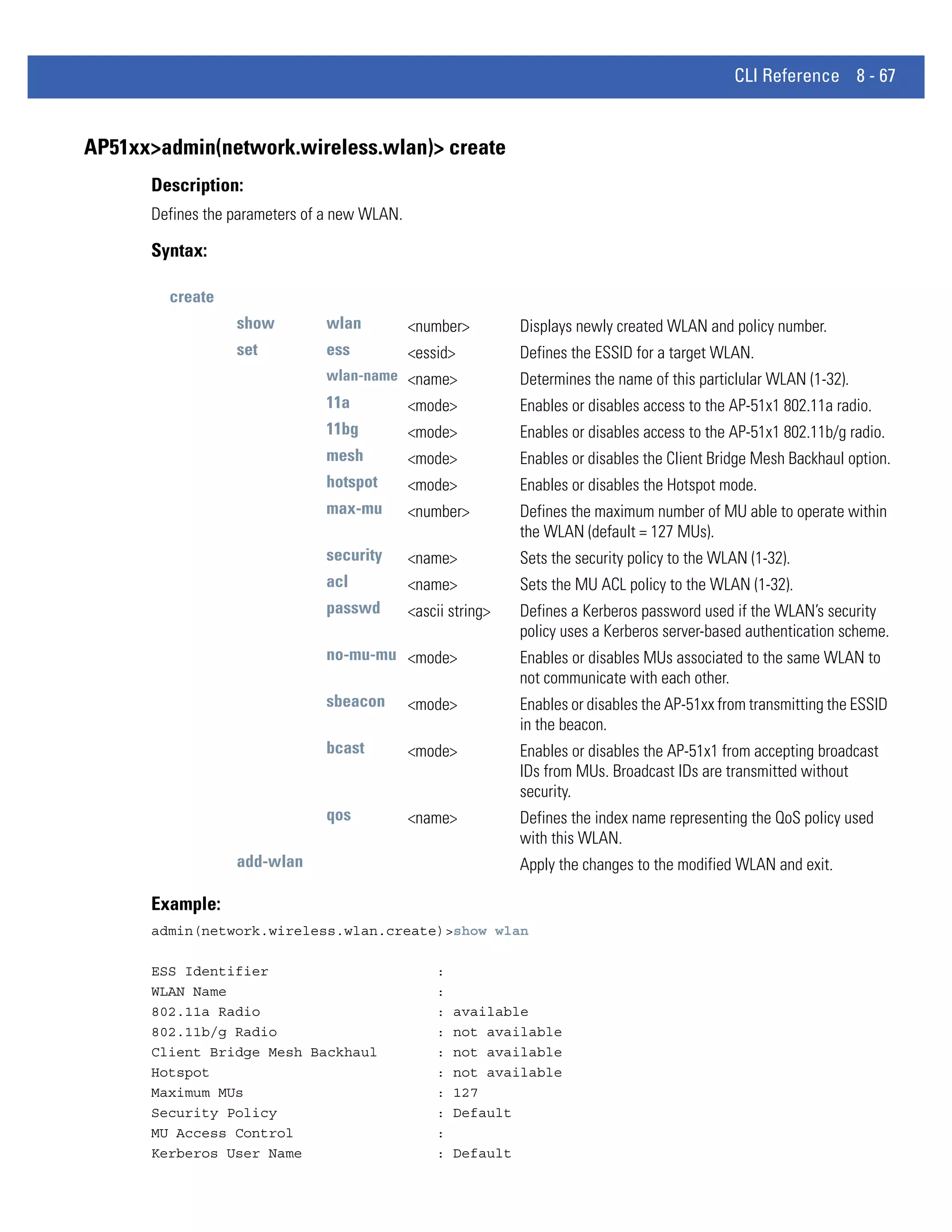
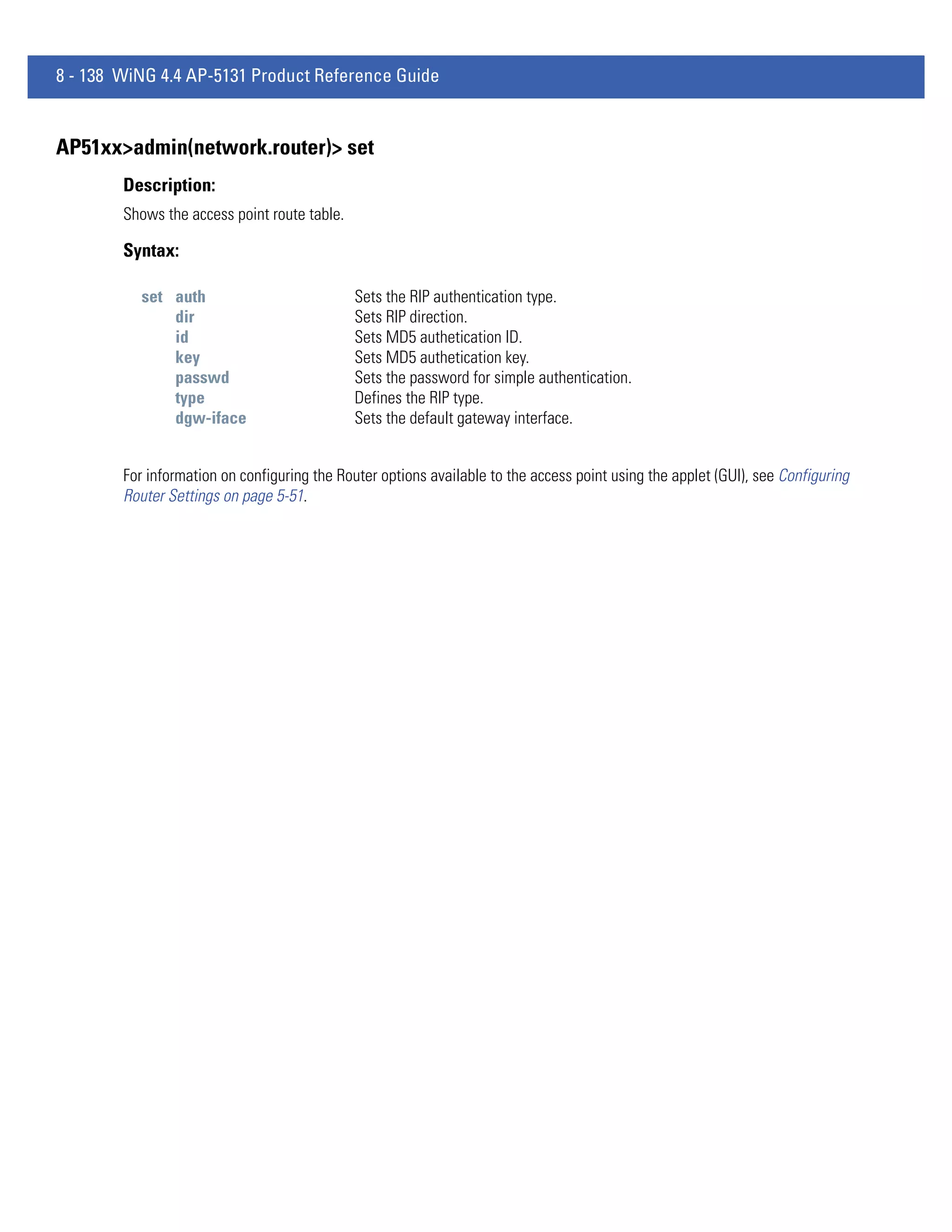
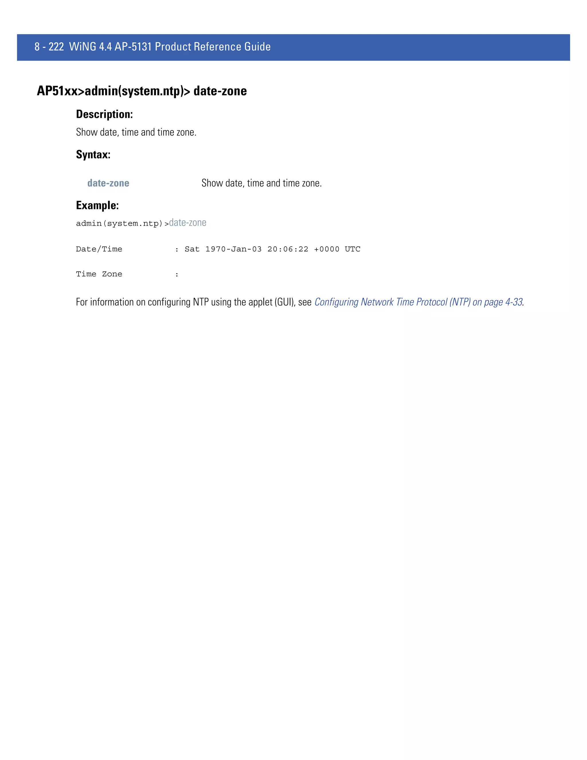
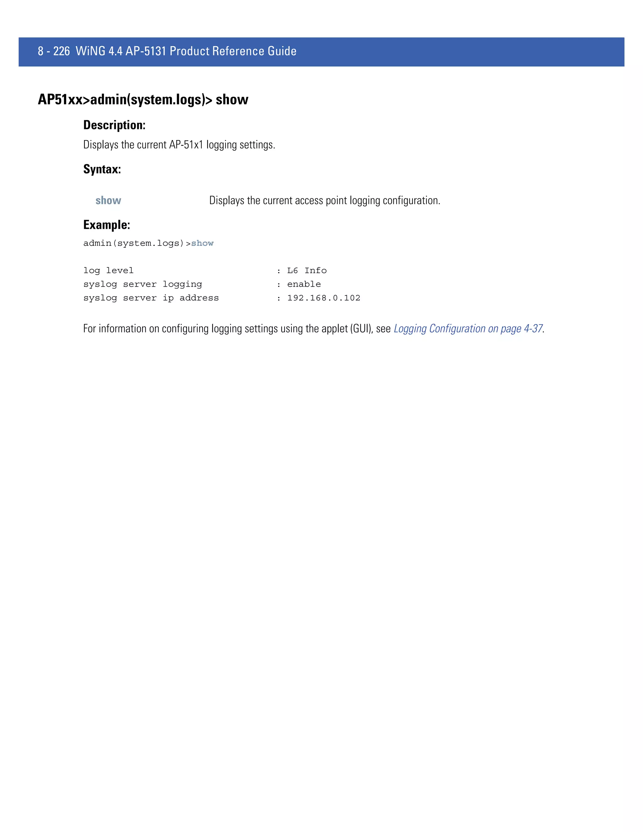
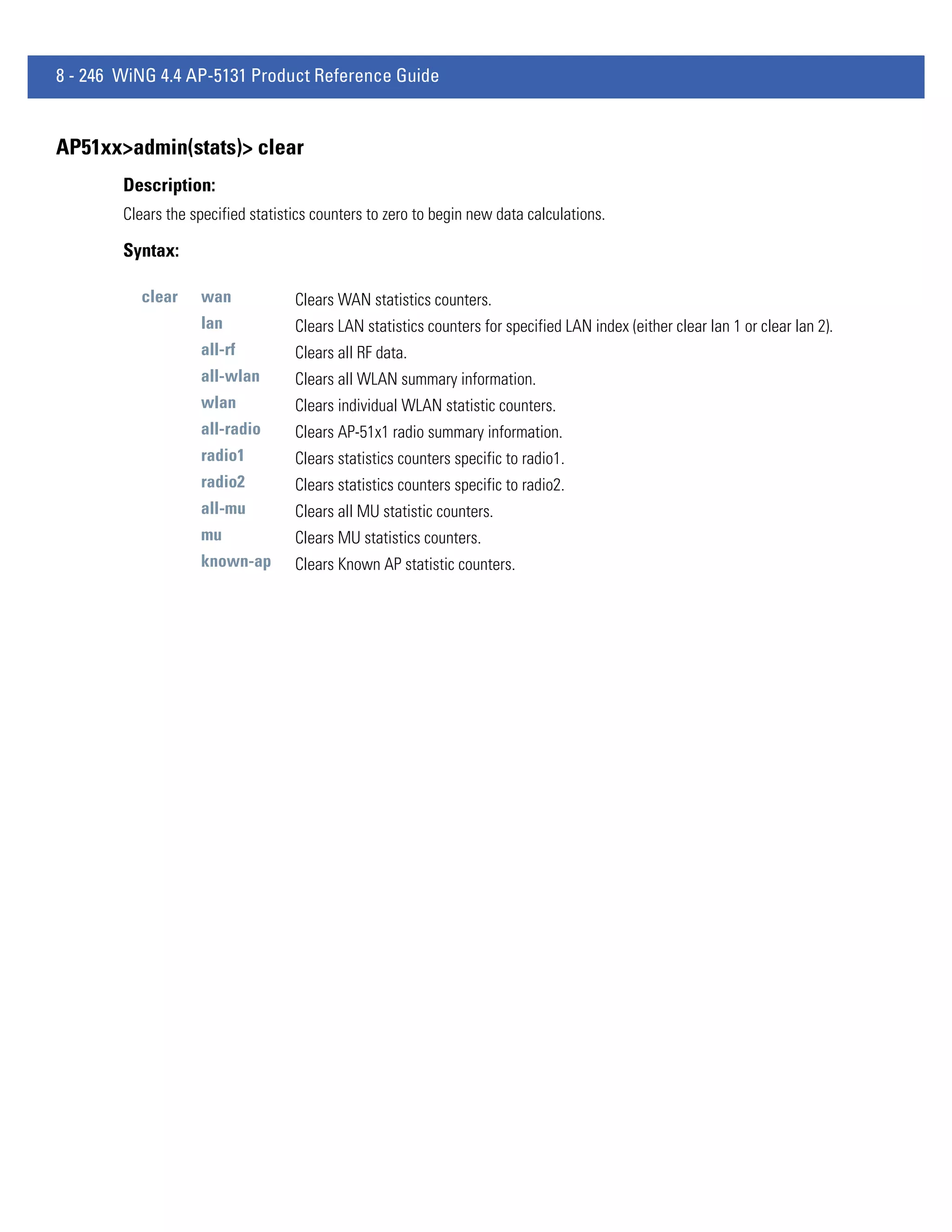
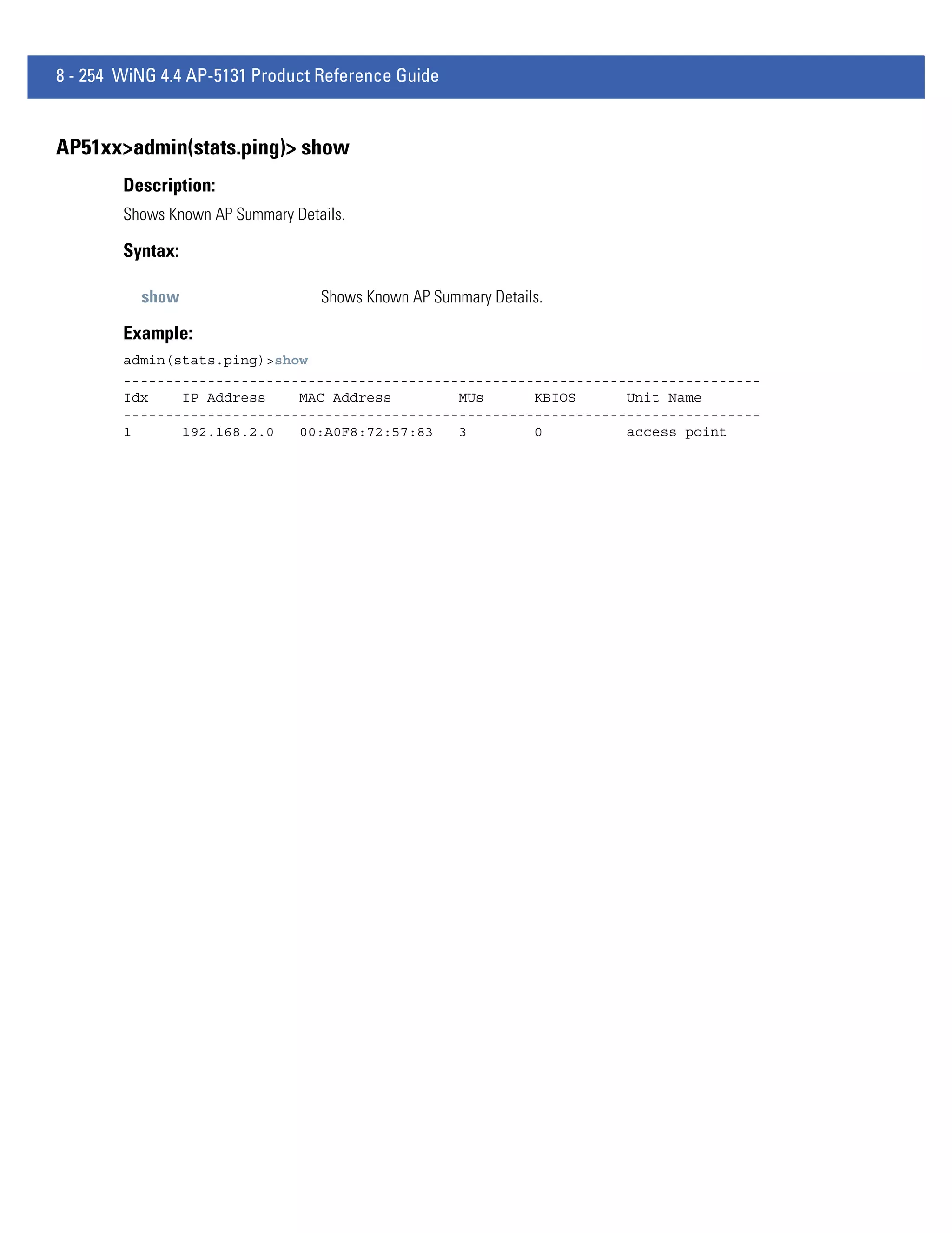
AP51xx>admin(system.config)> export
Description:
Exports the configuration from the system.
Syntax:
export ftp Exports the AP-51x1 configuration to the FTP server. Use the set command to set the server, user, password,
and file name before using this command.
tftp Exports the AP-51x1 configuration to the TFTP server. Use the set command to set the IP address for the
TFTP server before using the command.
terminal Exports the AP-51x1 configuration to a terminal.
Example:
Export FTP Example:
admin(system.config)>set server 192.168.22.12
admin(system.config)>set user myadmin
admin(system.config)>set file config.txt
admin(system.config)>set passwd
admin(system.config)>export ftp
Export operation : [ Started ]
Building configuration file : [ Done ]
File transfer : [ In progress ]
File transfer : [ Done ]
Export Operation : [ Done ]
Export TFTP Example:
admin(system.config)>set server 192.168.0.101
admin(system.config)>set file config.txt
admin(system.config)>export tftp
Export operation : [ Started ]
Building configuration file : [ Done ]
File transfer : [ In progress ]
File transfer : [ Done ]
Export Operation : [ Done ]
CAUTION Make sure a copy of the AP-51x1’s current configuration is exported (to a secure location) before
! exporting the access point’s configuration, as you will want a valid version available in case errors are
encountered with the configuration export.
For information on importing/exporting access point configurations using the applet (GUI), see Importing/Exporting
Configurations on page 4-39.](https://image.slidesharecdn.com/motorolasolutionswing4-4ap51xxaccesspointproductreferenceguidepartno-72e-157066-01rev-a-120807142110-phpapp02/75/Motorola-solutions-wing-4-4-ap51xx-access-point-product-reference-guide-part-no-72-e-157066-01-rev-a-506-2048.jpg)
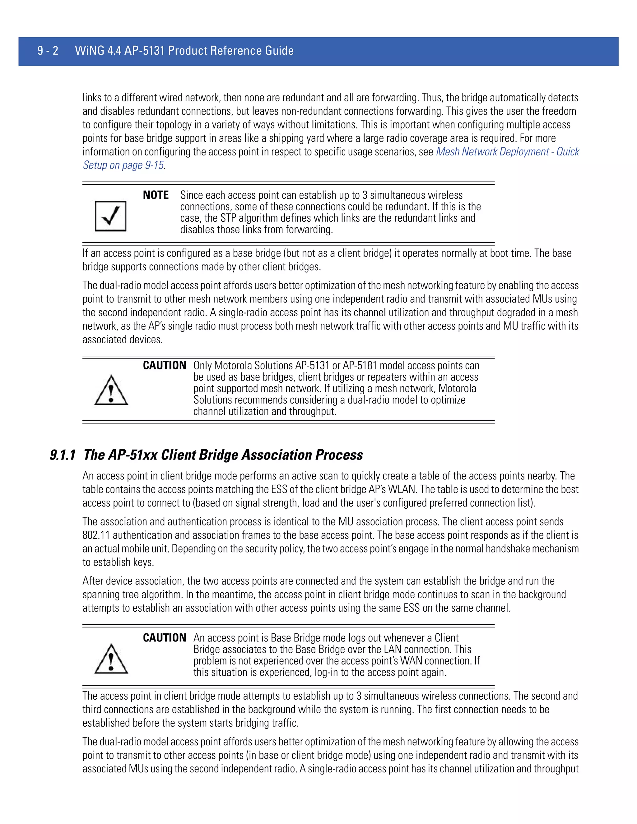
![CLI Reference 8 - 237
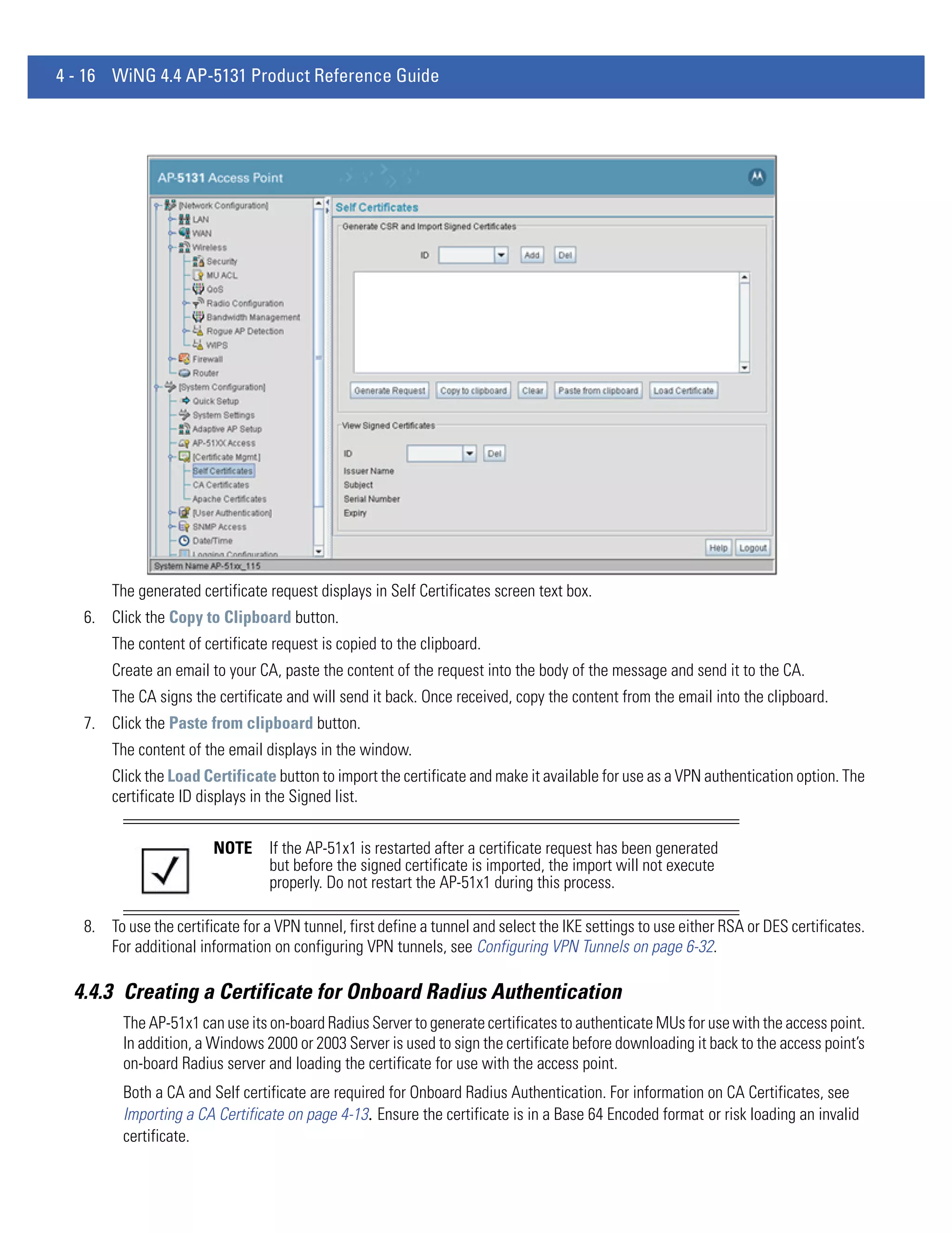
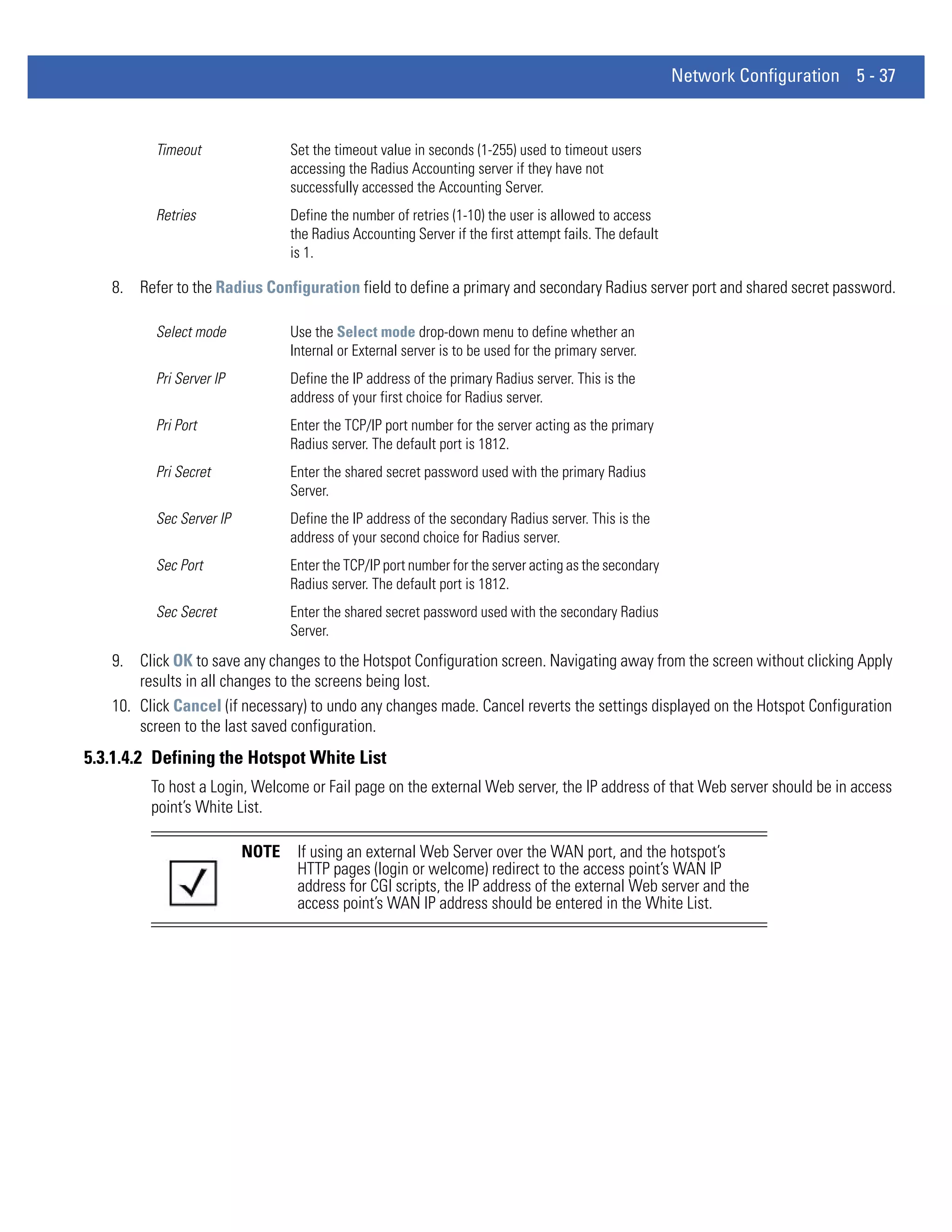
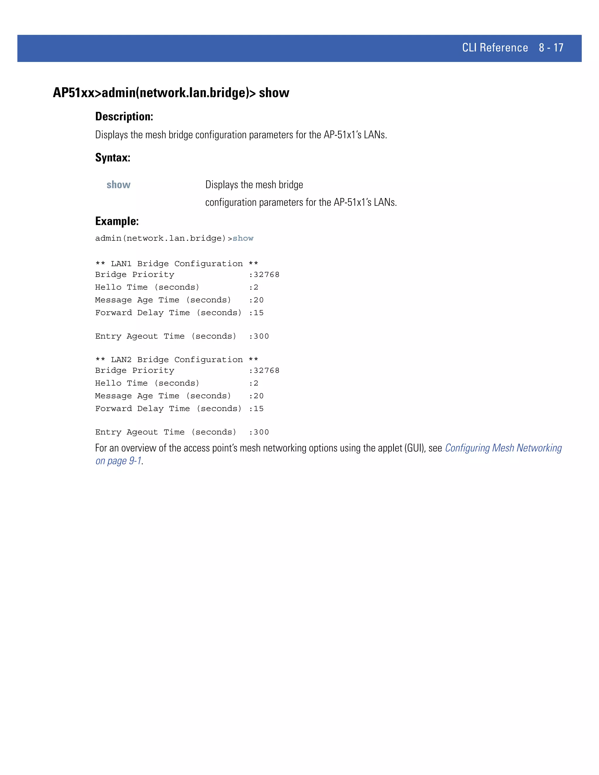
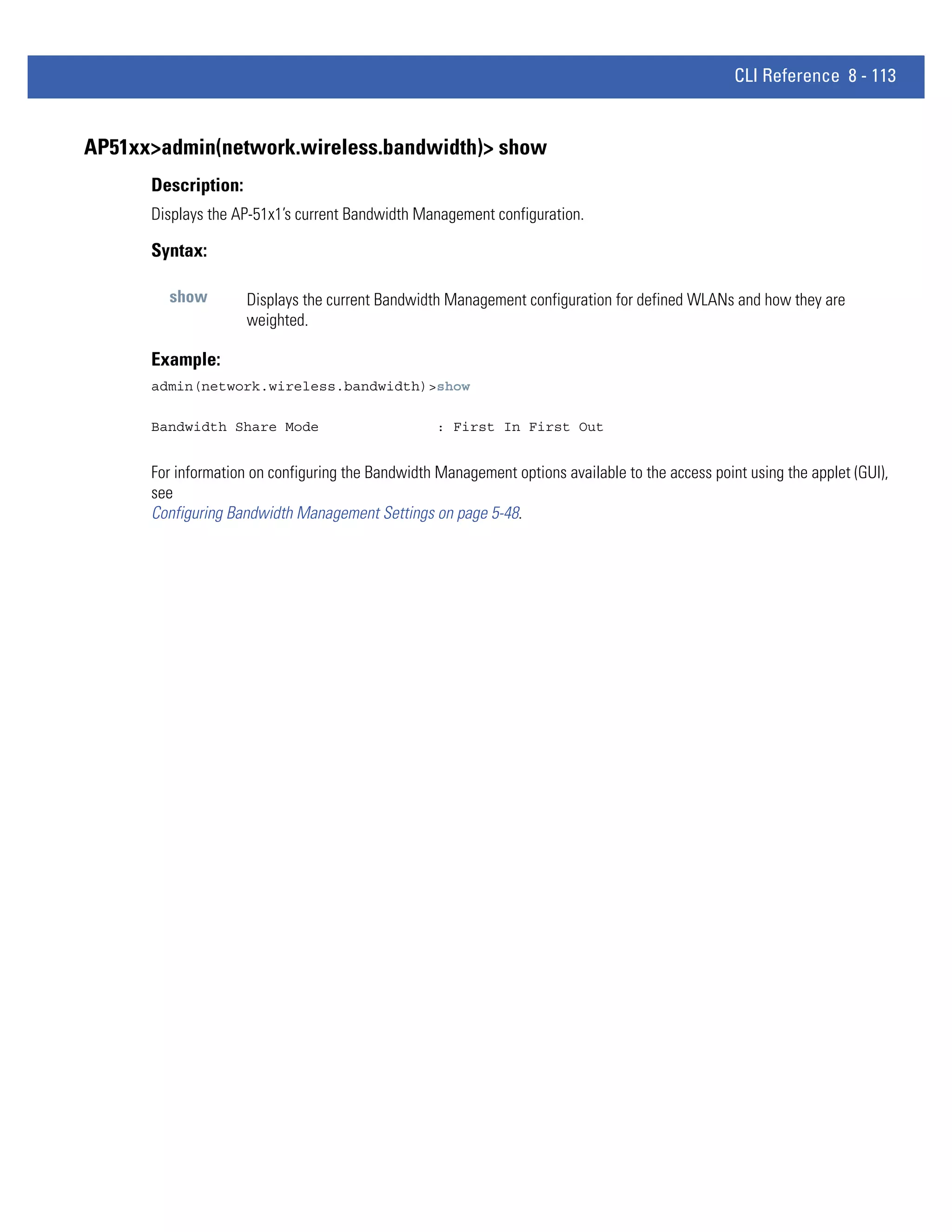
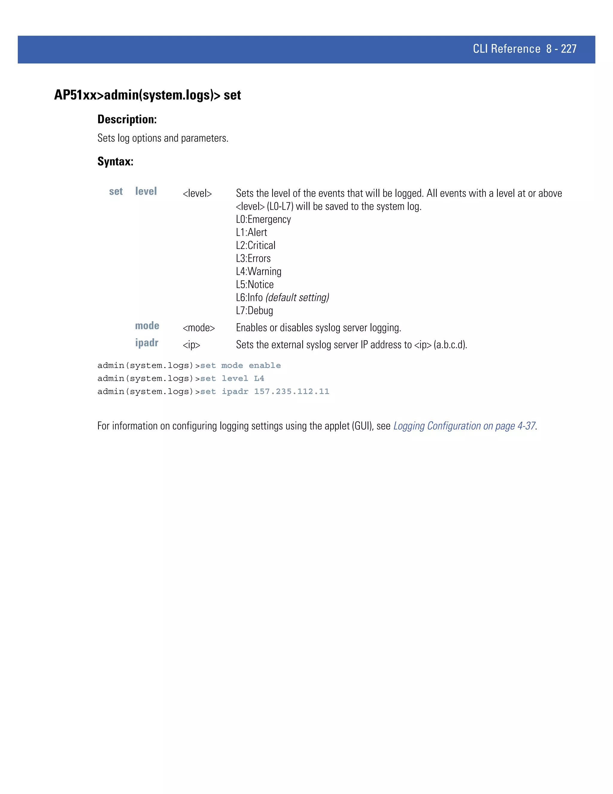
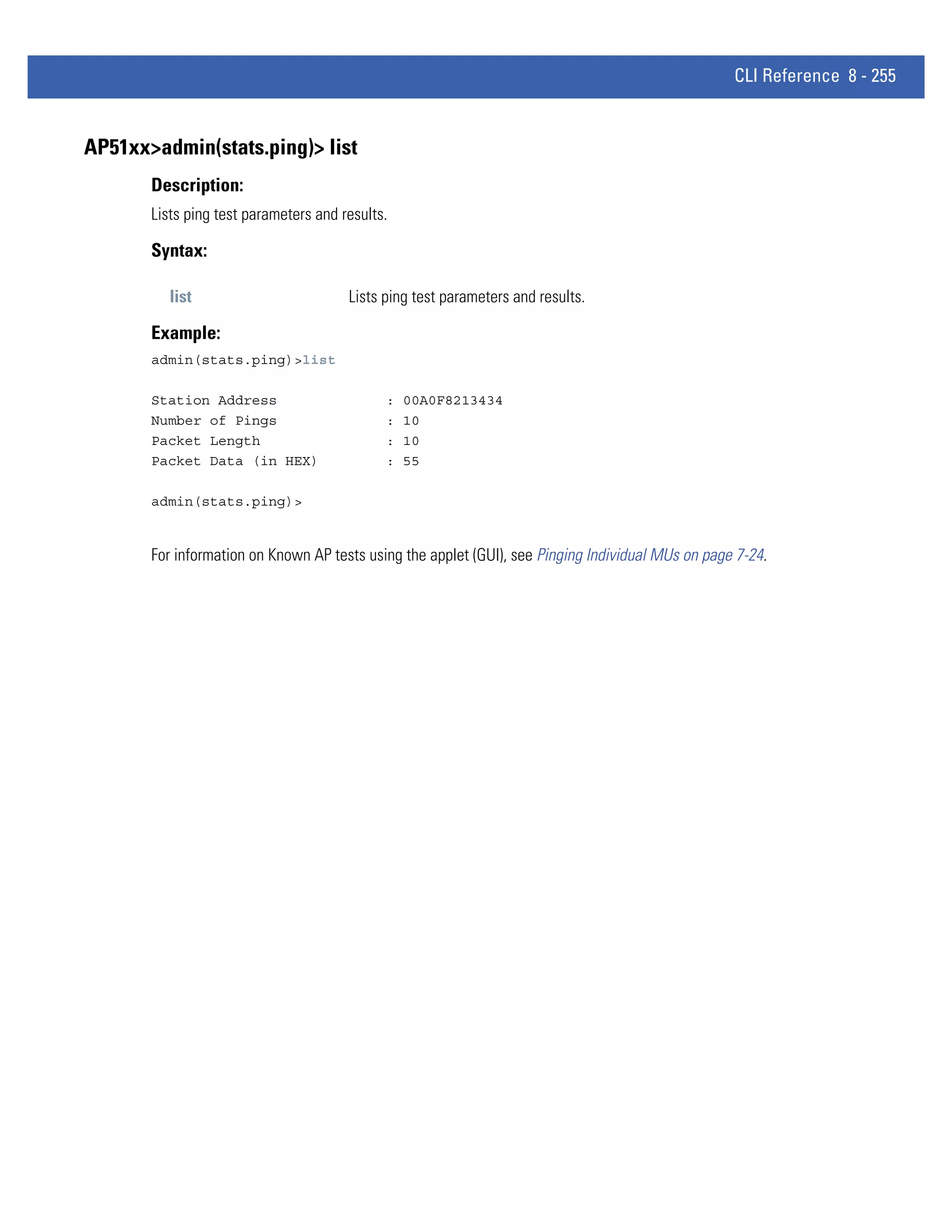
AP51xx>admin(system.config)> import
Description:
Imports the AP-51x1 configuration to the access point. Errors could display as a result of invaid configuration parameters.
Correct the sepcified lines and import the file again until the import operation is error free.
Syntax:
import ftp Imports the AP-51x1 configuration file from the FTP server. Use the set command to set the server,
user, password, and file.
tftp Imports the AP-51x1 configuration from the TFTP server. Use the set command to set the server and
file.
Example:
Import FTP Example
admin(system.config>set server 192.168.22.12
admin(system.config>set user myadmin
admin(system.config)>set file config.txt
admin(system.config)>set passwd mysecret
admin(system.config)>import ftp
Import operation : [ Started ]
File transfer : [ In progress ]
File transfer : [ Done ]
Import operation : [ Done ]
Import TFTP Example
admin(system.config)>set server 192.168.0.101
admin(system.config)>set file config.txt
admin(system.config)>import tftp
Import operation : [ Started ]
File transfer : [ In progress ]
File transfer : [ Done ]
Import operation : [ Done ]
CAUTION A single-radio model access point cannot import/export its configuration to a dual-radio model access
! point. In turn, a dual-radio model access point cannot import/export its configuration to a single-radio
access point.
CAUTION Motorola Solutions discourages importing a 1.0 baseline configuration file to a 1.1 version access
! point. Similarly, a 1.1 baseline configuration file should not be imported to a 1.0 version access point.
Importing configurations between different version access point’s results in broken configurations,
since new features added to the 1.1 version access point cannot be supported in a 1.0 version access
point.
For information on importing/exporting access point configurations using the applet (GUI), see Importing/Exporting
Configurations on page 4-39.](https://image.slidesharecdn.com/motorolasolutionswing4-4ap51xxaccesspointproductreferenceguidepartno-72e-157066-01rev-a-120807142110-phpapp02/75/Motorola-solutions-wing-4-4-ap51xx-access-point-product-reference-guide-part-no-72-e-157066-01-rev-a-507-2048.jpg)


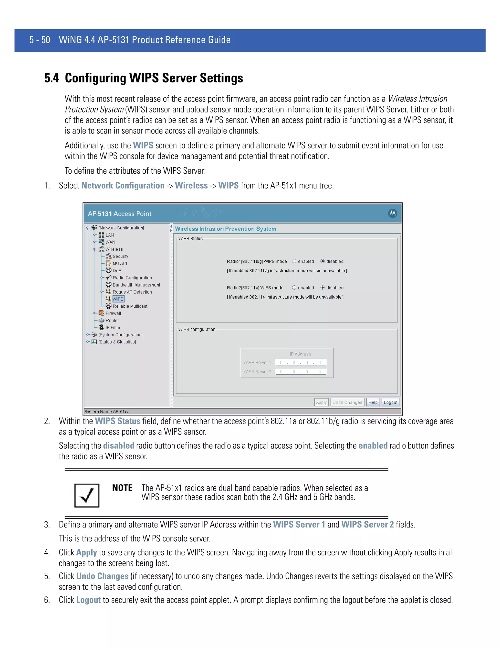
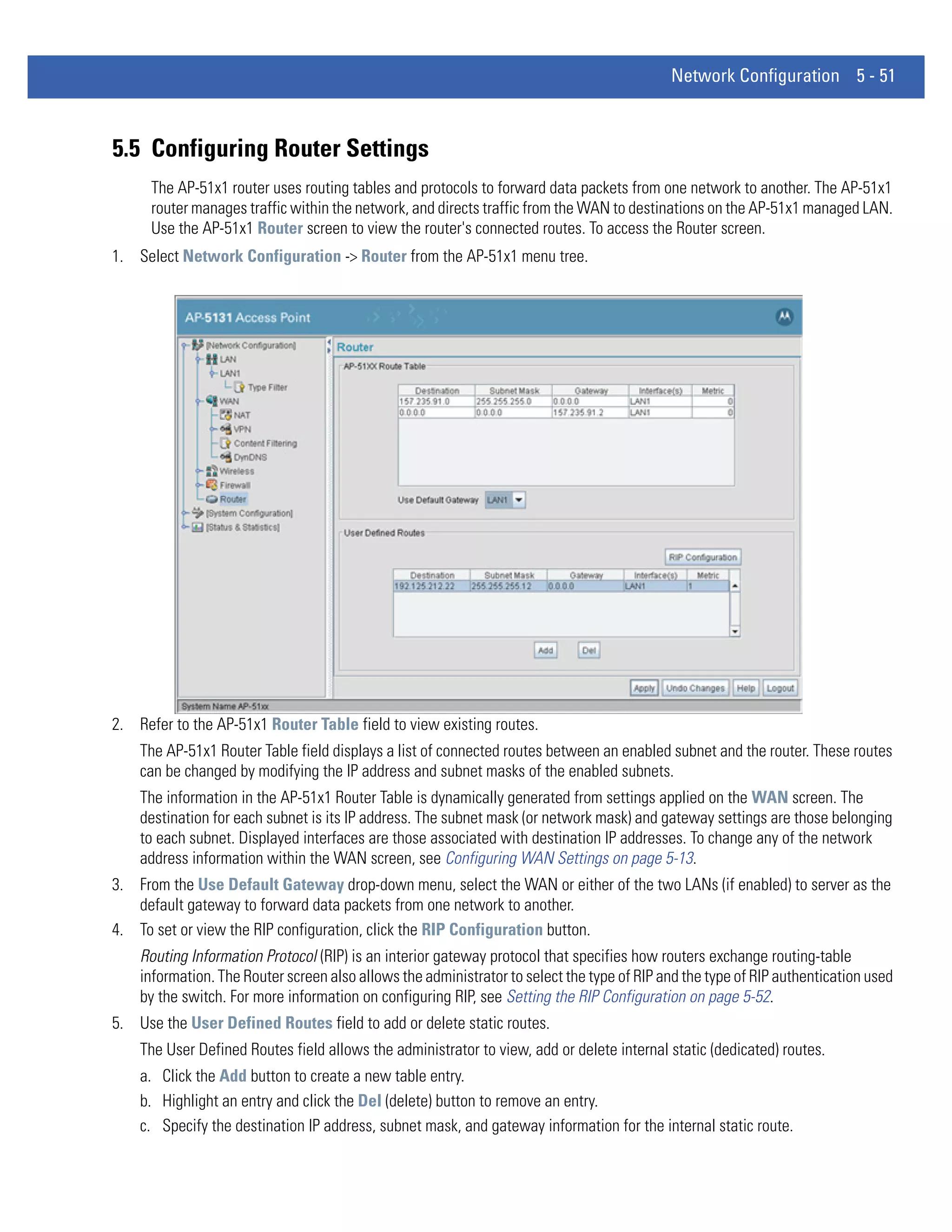
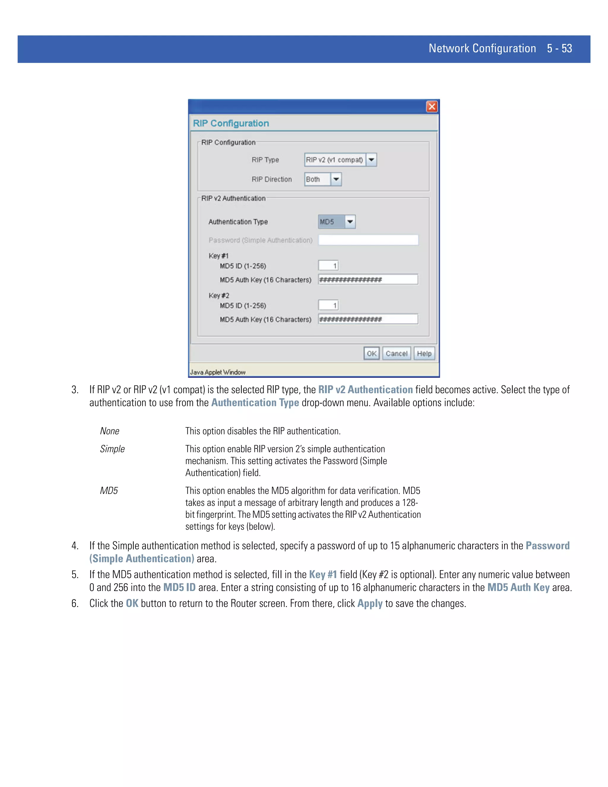
This document provides a product reference guide for the Motorola Solutions AP 5131 wireless access point. It includes sections on new features of the AP 5131 such as WIPS support, trusted host management, and adaptive AP functionality. The guide also covers an overview of the AP 5131's features which include dual radio options, separate LAN and WAN ports, mounting options, quality of service support, security, management access and more. It provides information on the device's capabilities and specifications.


![Coded Agents – with UiPath SDK + LangGraph [Virtual Hands-on Workshop]](https://cdn.slidesharecdn.com/ss_thumbnails/codedagentsdeck-251215155422-5497c599-thumbnail.jpg?width=640&height=640&fit=bounds)


