Downloaded 345 times


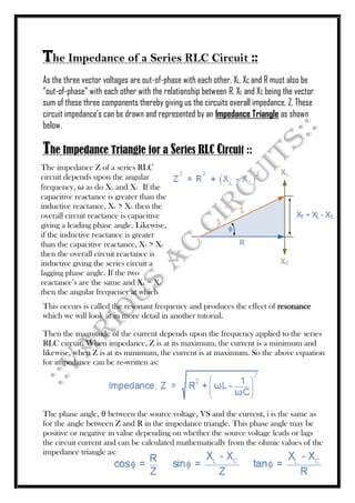


The document discusses alternating current (AC) waveforms, detailing their characteristics such as periodic time, frequency, amplitude, and root-mean-square (RMS) value. It explains the methods for calculating RMS values through graphical and analytical approaches, along with the significance of average values in AC systems. Additionally, it covers the behavior of AC in different circuit elements like resistors and inductors, emphasizing concepts like phasors and phase relationships in AC circuits.