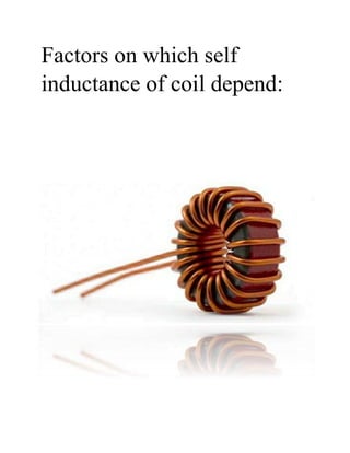
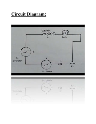
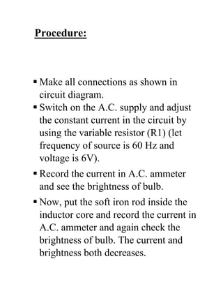
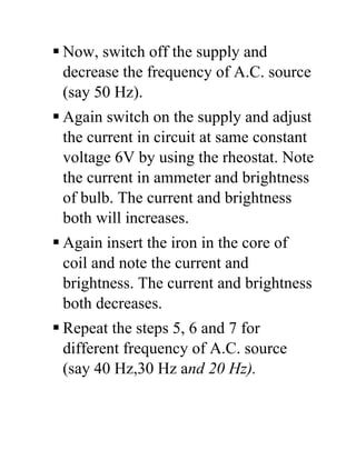
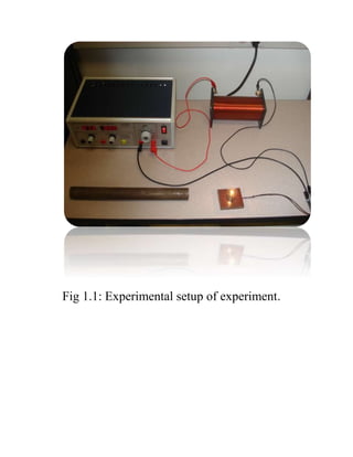
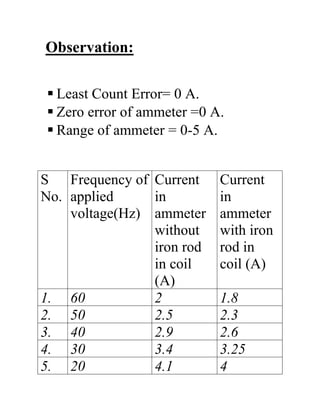
Factors on which self
inductance of coil depend:
Objective:
To study the factors on which the Self
Inductance of a coil depends by
observing the effect of this coil, when put
in series with a resistor (bulb) in a circuit
fed up by an A.C. source of adjustable
frequency.
Acknowledgement:
I would like to express my special thanks of
gratitude to my teacher Mr. Sunil and our
Principal Ms. Asha. Reddy who have given me
the golden opportunity to do this wonderful
project on the topic which also helped me in
doing a lot of Research and I came to know
about so many new things. I am really thankful
to them.
Secondly I would also like to thank my parents
and friends who helped me a lot in finalizing this
project within the limited time frame.
INDEX
 Introduction
 Aim
 Apparatus Required
 Theory
 Circuit Diagram
 Procedure
 Observations
 Result
 Precautions
 Sources of Error
 Bibliography
Introduction:
There are four basic factors of inductor
construction determining the amount of
inductance created. These factors all
indicate inductance by affecting how
much magnetic field flux will develop
for a given amount of magnetic field
force (current through the inductor’s
wire coil.
The factors are:-
• NUMBER OF WIRE WRAPS, OR
“TURNS” IN THE COIL.
• COIL AREA.
• COIL LENGTH.
• CORE MATERIAL.
Aim:
To study the factor on which the
Self Inductance of a coil depends
by observing the effect of this coil,
when put in series with a resistor
(bulb) in a circuit fed up by an A.C.
source of adjustable frequency.
Material Required:
A coil of large turns, A.C. source of
adjustable frequency, an electric bulb, (6
V) A.C. ammeter of suitable range,
rheostat, a soft iron rod, one way key,
connecting wires etc.
Theory:
Self Inductance is the property of a coil
which opposes the change in current
through it. The Self Inductance of a coil
(long solenoid) is
L =μ0μr N
2
A
Where μr= Relative magnetic
permeability of magnetic material,
μr = μμ
μ°
 N= Total number of turns in solenoid
 A= Area of cross section of solenoid
 l= Length of solenoid
Hence, the Self Inductance depends upon
• No. of turns (N), L α N2
• Geometry of coil, L=A , L α 1/l
• Nature of core material, L= μ
When an inductor is connected in series
with a resistor (bulb) with a variable
source of frequency, then current flowing
in the bulb is
I rms=E
rms
Z
Where Z= (R2
+ ω2
L2
)½
=Impedance of
the A.C. Circuit
R= Resistance of bulb
L= Self Inductance of coil
ω = 2πf = Angular frequency of
A.C. source.
The brightness of bulb i.e. Heat
generated in bulb is
H= I2
rmsZt
The brightness of bulb i.e. Heat
generated in bulb is
H= I2
rmsZt
Or,
P=H/t= I2
rmsZ
P= I2
rms(R2
+ ω2
L2
)½
Circuit Diagram:
Procedure:
 Make all connections as shown in
circuit diagram.
 Switch on the A.C. supply and adjust
the constant current in the circuit by
using the variable resistor (R1) (let
frequency of source is 60 Hz and
voltage is 6V).
 Record the current in A.C. ammeter
and see the brightness of bulb.
 Now, put the soft iron rod inside the
inductor core and record the current in
A.C. ammeter and again check the
brightness of bulb. The current and
brightness both decreases.
 Now, switch off the supply and
decrease the frequency of A.C. source
(say 50 Hz).
 Again switch on the supply and adjust
the current in circuit at same constant
voltage 6V by using the rheostat. Note
the current in ammeter and brightness
of bulb. The current and brightness
both will increases.
 Again insert the iron in the core of
coil and note the current and
brightness. The current and brightness
both decreases.
 Repeat the steps 5, 6 and 7 for
different frequency of A.C. source
(say 40 Hz,30 Hz and 20 Hz).
Fig 1.1: Experimental setup of experiment.
Observation:
 Least Count Error= 0 A.
 Zero error of ammeter =0 A.
 Range of ammeter = 0-5 A.
S
No.
Frequency of
applied
voltage(Hz)
Current
in
ammeter
without
iron rod
in coil
(A)
Current
in
ammeter
with iron
rod in
coil (A)
1. 60 2 1.8
2. 50 2.5 2.3
3. 40 2.9 2.6
4. 30 3.4 3.25
5. 20 4.1 4
Result:
• The current in the circuit decrease on
inserting the iron rod in the core of
coil at constant frequency of applied
voltage and brightness of bulb
decreases and vice-versa.
• The current in the circuit increases on
decreasing the frequency of applied
voltage and vice-versa. Therefore, the
brightness of bulb increases.
Precautions:
• The coil should have large number of
turns.
• Current should be passed for a small
time to avoid the heating effect.
• There should not be parallax in taking
the reading of ammeter.
Source of Error:
• The resistance of circuit may
increases slightly due to heating effect
of current.
•There may be eddy current
Bibliography:
1)https://www.google.com/url?sa=t&s
ource=web&rct=j&url=https://en.wiki
pedia.org/wiki/Inductance&ved=2ahU
KEwj08Iniro7lAhUJqI8KHTf0AnYQFj
ADegQIBBAB&usg=AOvVaw2P7iDjtF
kUuM4sVZ3Xvuee.
2)https://www.google.com/url?sa=t&s
ource=web&rct=j&url=https://www.u
kessays.com/essays/education/self-
induction-and-mutual-
induction.php&ved=2ahUKEwj08Iniro
7lAhUJLPrKSTgDiDwgKYZPHV&cshi
d=1570596884921.
Factors_On_Which_Self_Inductance_Of_Coil (2) (1).docx

Factors_On_Which_Self_Inductance_Of_Coil (2) (1).docx

  • 1.
    Factors on whichself inductance of coil depend:
  • 2.
    Objective: To study thefactors on which the Self Inductance of a coil depends by observing the effect of this coil, when put in series with a resistor (bulb) in a circuit fed up by an A.C. source of adjustable frequency.
  • 3.
    Acknowledgement: I would liketo express my special thanks of gratitude to my teacher Mr. Sunil and our Principal Ms. Asha. Reddy who have given me the golden opportunity to do this wonderful project on the topic which also helped me in doing a lot of Research and I came to know about so many new things. I am really thankful to them. Secondly I would also like to thank my parents and friends who helped me a lot in finalizing this project within the limited time frame.
  • 4.
    INDEX  Introduction  Aim Apparatus Required  Theory  Circuit Diagram  Procedure  Observations  Result  Precautions  Sources of Error  Bibliography
  • 5.
    Introduction: There are fourbasic factors of inductor construction determining the amount of inductance created. These factors all indicate inductance by affecting how much magnetic field flux will develop for a given amount of magnetic field force (current through the inductor’s wire coil.
  • 6.
    The factors are:- •NUMBER OF WIRE WRAPS, OR “TURNS” IN THE COIL. • COIL AREA. • COIL LENGTH. • CORE MATERIAL.
  • 7.
    Aim: To study thefactor on which the Self Inductance of a coil depends by observing the effect of this coil, when put in series with a resistor (bulb) in a circuit fed up by an A.C. source of adjustable frequency.
  • 8.
    Material Required: A coilof large turns, A.C. source of adjustable frequency, an electric bulb, (6 V) A.C. ammeter of suitable range, rheostat, a soft iron rod, one way key, connecting wires etc.
  • 9.
    Theory: Self Inductance isthe property of a coil which opposes the change in current through it. The Self Inductance of a coil (long solenoid) is L =μ0μr N 2 A Where μr= Relative magnetic permeability of magnetic material, μr = μμ μ°  N= Total number of turns in solenoid
  • 10.
     A= Areaof cross section of solenoid  l= Length of solenoid Hence, the Self Inductance depends upon • No. of turns (N), L α N2 • Geometry of coil, L=A , L α 1/l • Nature of core material, L= μ When an inductor is connected in series with a resistor (bulb) with a variable source of frequency, then current flowing in the bulb is I rms=E rms Z
  • 11.
    Where Z= (R2 +ω2 L2 )½ =Impedance of the A.C. Circuit R= Resistance of bulb L= Self Inductance of coil ω = 2πf = Angular frequency of A.C. source. The brightness of bulb i.e. Heat generated in bulb is H= I2 rmsZt The brightness of bulb i.e. Heat generated in bulb is H= I2 rmsZt Or, P=H/t= I2 rmsZ P= I2 rms(R2 + ω2 L2 )½
  • 13.
  • 14.
    Procedure:  Make allconnections as shown in circuit diagram.  Switch on the A.C. supply and adjust the constant current in the circuit by using the variable resistor (R1) (let frequency of source is 60 Hz and voltage is 6V).  Record the current in A.C. ammeter and see the brightness of bulb.  Now, put the soft iron rod inside the inductor core and record the current in A.C. ammeter and again check the brightness of bulb. The current and brightness both decreases.
  • 15.
     Now, switchoff the supply and decrease the frequency of A.C. source (say 50 Hz).  Again switch on the supply and adjust the current in circuit at same constant voltage 6V by using the rheostat. Note the current in ammeter and brightness of bulb. The current and brightness both will increases.  Again insert the iron in the core of coil and note the current and brightness. The current and brightness both decreases.  Repeat the steps 5, 6 and 7 for different frequency of A.C. source (say 40 Hz,30 Hz and 20 Hz).
  • 16.
    Fig 1.1: Experimentalsetup of experiment.
  • 17.
    Observation:  Least CountError= 0 A.  Zero error of ammeter =0 A.  Range of ammeter = 0-5 A. S No. Frequency of applied voltage(Hz) Current in ammeter without iron rod in coil (A) Current in ammeter with iron rod in coil (A) 1. 60 2 1.8 2. 50 2.5 2.3 3. 40 2.9 2.6 4. 30 3.4 3.25 5. 20 4.1 4
  • 18.
    Result: • The currentin the circuit decrease on inserting the iron rod in the core of coil at constant frequency of applied voltage and brightness of bulb decreases and vice-versa. • The current in the circuit increases on decreasing the frequency of applied voltage and vice-versa. Therefore, the brightness of bulb increases.
  • 19.
    Precautions: • The coilshould have large number of turns. • Current should be passed for a small time to avoid the heating effect. • There should not be parallax in taking the reading of ammeter.
  • 20.
    Source of Error: •The resistance of circuit may increases slightly due to heating effect of current. •There may be eddy current
  • 21.