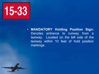
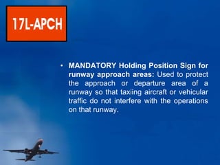
SlideShare a Scribd company logo
Airport Familiarization
Signage
• MANDATORY Holding Position Sign:
Denotes entrance to runway from a
taxiway. Located on the left side of the
taxiway within 10 feet of hold position
markings.
• MANDATORY Holding Position Sign for
runway approach areas: Used to protect
the approach or departure area of a
runway so that taxiing aircraft or vehicular
traffic do not interfere with the operations
on that runway.
• MANDATORY ILS Holding Position
Sign: Denotes entrance to area to be
protected for an ILS signal or approach
airspace.
• MANDATORY No Entry Sign: Denotes
where aircraft entry is prohibited.
• Taxiway Location Sign: The inscription is
the designation of the taxiway on which
the aircraft or vehicle is located. These
signs are installed along taxiways, either
by themselves or in conjunction with
direction signs.
A
• Runway Location Sign: The inscription is
the designation of the runway on which the
aircraft is located. These signs are
intended to complement the information
available to pilots through their magnetic
compass. Typically, they are installed
where the proximity of two or more
runways to one another could cause pilots
to be confused as to which runway they
are on.
• Runway Approach Area Boundary Sign:
This sign, which faces the runway and is
visible to the pilot exiting the runway, is
located adjacent to the holding position
marking on the pavement. The sign is
intended to provide pilots with another
visual cue which they can use as a guide
in deciding when they are “clear of the
runway”.
• ILS Critical Area Boundary Sign:
Indicates when you are safely clear of the
ILS critical area. It is located directly
beside the ILS holding position markings.
While ILS approaches are in use, taxi past
the sign before stopping on the taxiway.
• Runway Exit Direction Sign: This sign
will indicate the approaching taxiway while
on the runway. In this example, taxiway
Alpha is approaching to the right.
A
• Outbound Destination Sign: Runways
27 and 33 are to your right.
• Never co-located or combined with other
signs.
• Inbound Destination Sign: The military
installation is to your right. Other
information signs are Cargo, Term
(Terminal), Ramp, etc.
• Taxiway Ending Marker: This sign
indicates the termination of the taxiway. It
is located at the far end of the intersection.
• Runway Distance Remaining Sign: have
a black background with white numbers.
The numbers indicate the distance of the
remaining runway in thousands of feet.
Markings
• Runway Holding Position Marking: The
solid lines are always on the side where
the aircraft and vehicles are to hold. They
are located on all taxiways that intersect
runways approximately 300’ from the
runway centerline.
• ILS Holding Position Marking : These
markings identify where aircraft and
vehicles are to stop when instructed to
hold short of the ILS critical areas.
• Taxiway/Taxiway Holding Position
Marking : Denotes location on taxiway or
apron where aircraft hold short of another
taxiway.
• Non – Movement Area Boundary
Marking : Delineates movement area
under control of ATCT, from non-
movement area. The solid line is located
on the Non-Movement Area side while the
dashed line is located on the Movement
Area side.
• Taxiway Centerline Marking : Solid
yellow line that provides a visual cue for
taxiing along a designated path.
• Enhanced Taxiway Centerline Marking :
Provides visual cue to help identify
location of hold position. (150 feet in
length).
• Taxiway Edge Marking : used to define
the edge of the taxiway. They are
primarily used when the taxiway edge
does not correspond with the edge of the
pavement.
• Vehicle Roadway Marking : “Zipper
Stripes” mark areas intended for vehicle
traffic. Solid white stripes may also be
used to define vehicle roadways located
on an aircraft apron area.
• Closed Runway and Taxiway Marking -
Located at both ends of permanently
closed runways and at 1,000-foot intervals.
It is also placed at taxiway entrances if
they are permanently closed.
32
• Apron Entry Point (AEP) : A unique
system of identifying the numerous
taxilanes that lead from the ramps onto the
taxiways.
36
R
Runway Edge Marking
(36” wide)
Runway Centerline Marking
(120’ long, 36” wide)
Touchdown Zone Marking
(75’ long)
Fixed Distance Marking
(Aiming Point)
(150’ long)
Runway Designation
Threshold Marking
(150’ long)
Threshold Bar
Chevron
20’
500’
1000’
1500’
2000’
2500’
3000’
R
U
N
W
A
Y
M
A
R
K
I
N
G
S
D
I
S
P
L
A
C
E
D
T
H
R
E
S
H
O
L
D
L
13
Demarcation Bar
3’ wide
Demarcation Bar -
delineates a runway with a
displaced threshold from a
blast pad, stopway or
taxiway that precedes the
runway.
Lighting
R
U
N
W
A
Y
L
I
G
H
T
I
N
G
36
R
• Edge Lights
– Spaced approximately
200’ apart.
– White
– Amber the last 2000’
• Centerline Lights
– Spaced approximately
50’ apart.
– White
– Alternating Red/White
3000’ – 1000’
– Solid Red from 1000’
to end
Runway Take-Off Hold Lights
Runway Entrance Lights REL’s
Precision Approach Path Indicator
Too Low
Slightly Low
Correct
Approach
Angle
Slightly High
Too High
A light system positioned beside the runway that consists of four boxes of
lights that provide a visual indication of an aircraft's position on the glidepath
for the associated runway. The PAPI is usually located on the left side of the
runway and can be seen up to five miles during the day and twenty miles at
night.
• Runway Guard Lights : These lights are
intended to alert vehicles and aircraft of a
runway/taxiway intersection and are
located on either side of the holding
position marking.
T
A
X
I
W
A
Y
L
I
G
H
T
I
N
G
• Edge Lights
- Blue
- 200’ apart.
• Center Lights
- Green
- 50’ apart.
• Intersection
- (1) Amber
• Denied Access
- Red
X
ILS
Instrument Landing System
A ground-based instrument approach system that provides
precision guidance to an aircraft approaching a runway,
using a combination of radio signals and, in many cases,
high-intensity lighting arrays to enable a safe landing during
instrument meteorological conditions (IMC), such as low
ceilings or reduced visibility due to fog, rain, or blowing snow.
The ILS consists of:
• the localizer transmitter;
• the glide path transmitter;
• the marker beacons
• the approach lighting system.
Localizer Antenna
The localizer provides
runway centerline guidance
to aircraft. The Localizer is
placed about 1,000 feet on
the far end of the
approached runway.
Glideslope Antenna
The Glide Slope is the
signal that provides vertical
guidance to the aircraft
during the ILS approach.
The standard glide-slope
path is 3° downhill to the
approach-end of the
runway. Follow it faithfully
and your altitude will be
precisely correct when you
reach the touchdown zone
of the runway.
ALSF-2 Runway
• A high intensity approach lighting system
that provides a visual lighting path for
landing aircraft on Cat II and Cat III
Runways.
• Lights are spaced 100’ apart starting from
the runway threshold. Usually a 2400-
foot-long array of lights but can be longer
or shorter depending on local terrain and
requirements.
• System control of the sequence flashing
lights is accomplished through the master
controller selecting one of three light
intensities: low, medium, or high. Both the
sequence flashing and the steady burning
light systems provide for either local or
remote control.
MALSR Runway
• Medium intensity approach lighting system
that provides a visual lighting path for
landing aircraft.
• Lights are spaced 200’ apart starting from
the Runway Threshold. Usually 2400 foot-
long array of lights but can be longer or
shorter depending on local terrain and
requirements.
• System control of the sequence flashing
lights is accomplished through the master
controller selecting one of three light
intensities: low, medium, or high. Both the
sequence flashing and the steady burning
light systems provide for either local or
remote control.
Wind Sock
Lighted and frangible
mounted wind socks must
be installed near the
approach end of each
runway, preferably opposite
the 1,000 foot mark and
150 feet off the left side of
the runway.
Runway
Specifications
East Side Runways
17R / 35L 17C / 35C 17L / 35R 13L / 31R
Length 13,400’ 13,400’ 8,500’ 8,375/9,000’
Width 200’ 150’ 150’ 200’
Shoulders 25’ 35’ 35’ 25’
Visual Slope
Indicator
4 Light PAPI 4 Light PAPI 4 Light PAPI 4 Light PAPI
Approach
Lights
17R – MALSR
35L - MALSR
17C – ALSF2
35C – ALSF2
17L – ALSF2
35R – ALSF2
31R - MALSR
NOTE: 13L length accounts for 625’ displaced threshold
West Side Runways
18L / 36R 18R / 36L 13R / 31L
Length 13,400’ 13,400’ 9300’
Width 200’ 150’ 150’
Shoulders 25’ 35’ 35’
Visual Slope Indicator 4 Light PAPI 4 Light PAPI 4 Light PAPI
Approach Lights 18L – MALSR
36R - MALSR
18R – ALSF2
36L - MALSR
13R - MALSR
Apparatus
Oshkosh Striker
• Water – 4500 gallons
• Foam – 525 gallons 3% AFFF
• Dry Chemical – 450 lbs Purple K
• Water Pump – Waterous, 1950 gpm
• Foam System
– Around the Pump Proportioner
• Roof Turret
– Flow – 375 - 750 gpm
– Reach – 200’
• Bumper Turret
– Flow – 600 - 1200 gpm
– Reach – 240’
– Dry Chemical @ 16 pps
• Under Truck Nozzles
– (5) @ 19 gpm
• Dual Agent Handline
– Dry Chemical @ 5 pps
TRIMAX
• Water – 150 gallons
• Foam – 5 gallons 3% AFFF
• Dry Chemical – 450 lbs
• Foam System - CAFS
• Bumper Turret
– Reach – 150’
– Aux Agent @ 16 pps
• Dual Agent Handline –
– Dry Chemical @ 5 pps
FAR 139
• Air Carrier Aircraft - an aircraft that is being operated by
an air carrier and is categorized as either a large air carrier
aircraft if designed for at least 31 passenger seats or a
small air carrier aircraft if designed for more than 9
passenger seats but less than 31 passenger seats.
• Air Carrier Operation - Air carrier operation means the
takeoff or landing of an air carrier aircraft and includes the
period of time from 15 minutes before until 15 minutes
after the takeoff or landing.
§ 139.5 Definitions
• Airport Operating Certificate - a certificate, issued under
this part, for operation of a Class I, II, III, or IV airport.
– Class I - an airport certificated to serve scheduled operations of
large air carrier aircraft that can also serve unscheduled passenger
operations of large air carrier aircraft and/or scheduled operations
of small air carrier aircraft.
• Average Daily Departures - the average number of
scheduled departures per day of air carrier aircraft
computed on the basis of the busiest 3 consecutive
calendar months of the immediately preceding 12
consecutive calendar months.
§ 139.5 Definitions
• Movement Area - the runways, taxiways, and other areas
of an airport that are used for taxiing, takeoff, and landing
of aircraft, exclusive of loading ramps and aircraft parking
areas.
• Surface Movement Ground Control System (SMGCS) –
A plan for U.S. Airports where scheduled Air Carriers are
authorized to conduct operations when the visibility is less
than 1,200 feet runway visual range (RVR)
§ 139.5 Definitions
• Theoretical Critical Fire Area
(TCA) - serves as a means of
categorizing aircraft in terms of
the magnitude of the potential
fire hazard in which they may
become involved.
• Practical Critical Fire Area
(PCA) – two thirds of the TCA
§ Miscellaneous Definitions
• Control Time - the time required from the arrival of the
first fire fighting vehicle and the beginning of agent
discharge to reduce the initial intensity of the fire by 90
percent. The equipment and techniques to be used should
be capable of controlling the fire in the PCA in 1 minute.
• Extinguishment Time - the time required from the
application of the agent of the first fire fighting vehicle to
the time the fire is extinguished.
§ 139.5 Definitions
• Runway Safety Area (RSA) – Safety areas for Runways
are 500’ wide or 250’ either side of the runway centerline
and 1000’ beyond each end of the runway.
• Taxiway Safety Area (TSA) – Safety Areas for Taxiways
constructed before January 1, 1988 are 200’ wide or 100’
from the taxiway centerline. Taxiway Safety Areas at DFW
constructed after January 1, 1988 are 214’ wide or 107’
from the centerline
• Obstacle Free Zone (OFZ) – a volume of airspace
centered above the runway that is 400’ wide and extends
200’ beyond each runway end.
• Index is determined by a combination of -
– The length of air carrier aircraft and the average daily departures of
air carrier aircraft.
– The longest aircraft with an average of five or more daily
departures determines the Index required for the airport.
• Index A includes aircraft less than 90’
• Index B includes aircraft 90’ – 126’
• Index C includes aircraft 126’ – 159’
• Index D includes aircraft 159’ – 200’
• Index E includes aircraft over 200’
§ 139.315 Index Determination
• Index A: One vehicle carrying at least―
– 500 pounds of sodium-based dry chemical, halon 1211, or clean
agent; or
– 450 pounds of potassium-based dry chemical and water with a
commensurate quantity of AFFF to total 100 gallons for
simultaneous dry chemical and AFFF application
§ 139.317 Equipment and Agents
• Index B: Two vehicles―
– One vehicle carrying at least 500lbs of sodium-based dry chemical,
halon 1211, or clean agent or 450 lbs. of potassium based dry
chemical.
– One vehicle carrying an amount of water and the commensurate
quantity of AFFF so the total quantity of water for foam production
carried by both vehicles is at least 1,500 gallons.
§ 139.317 Equipment and Agents
• Index C: Three Vehicles
– One vehicle carrying at least 500lbs of sodium-based dry chemical,
halon 1211, or clean agent or 450 lbs. of potassium based dry
chemical.
– Two vehicles carrying an amount of water and the commensurate
quantity of AFFF so the total quantity of water for foam production
carried by both vehicles is at least 3,000 gallons.
§ 139.317 Equipment and Agents
• Index D: Three vehicles –
– One vehicle carrying at least 500lbs of sodium-based dry chemical,
halon 1211, or clean agent or 450 lbs. of potassium based dry
chemical.
– Two vehicles carrying an amount of water and the commensurate
of AFFF so the total quantity of water for foam production carried
by all three vehicles is at least 4,000 gallons.
§ 139.317 Equipment and Agents
• Index E: Three vehicles –
– One vehicle carrying at least 500lbs of sodium-based dry chemical,
halon 1211, or clean agent or 450 lbs. of potassium based dry
chemical.
– Two vehicles carrying an amount of water and the commensurate
of AFFF so the total quantity of water for foam production carried
by all three vehicles is at least 6,000 gallons.
§ 139.317 Equipment and Agents
• Foam Discharge Capacity
– Apparatus with a capacity of at least 500 gallons of water for foam
production must be equipped with a turret. Vehicle turret discharge
capacities must be as follows:
Water Tank Capacity Turret Discharge Rate
500 – 2000 gallons 500 – 1000 gpm
> 2000 gallons 600 – 1200 gpm
§ 139.317 Equipment and Agents
• Agent Discharge Capacity
– Apparatus that is required to carry dry chemical, halon 1211, or
clean agent for compliance with Index requirements must meet one
of the following minimum discharge rates for the equipment
installed:
Hand Line 5 lbs. per second
Turret 16 lbs. per second
§ 139.317 Equipment and Agents
• AFFF quantity requirements
– Each vehicle required to carry AFFF must carry AFFF in an
appropriate amount to mix with twice the water required to be
carried by the vehicle.
§ 139.317 Equipment and Agents
• Vehicle Communications
– Each vehicle must be equipped with two-way voice radio
communications that provide for contact with at least-
• All other required emergency vehicles
• The air traffic control tower
• Fire stations.
§ 139.319 Operational Requirements
• Vehicle marking and lighting
– Each vehicle must:
• Have a flashing or rotating beacon; and
• Be painted or marked in colors to enhance contrast with the
background environment and optimize daytime and nighttime
visibility and identification
§ 139.319 Operational Requirements
• Vehicle readiness
– Any required vehicle that becomes inoperative to the extent that it
cannot perform as required must be replaced immediately with
equipment having at least equal capabilities. If replacement is not
available immediately, the certificate holder must notify the
Regional Airports Divisional Manager and each air carrier using the
airport. If the required index level of capability is not restored within
48 hours, the airport operator, must limit air carrier operations on
the airport to those compatible with the index corresponding to the
remaining operative rescue and firefighting equipment
§ 139.319 Operational Requirements
• Response requirements
– Within 3 minutes from the time of the alarm, at least one required
aircraft rescue and firefighting vehicle must reach the midpoint of
the farthest runway serving air carrier aircraft from its assigned post
or reach any other specified point of comparable distance on the
movement area that is available to air carriers, and begin
application of extinguishing agent.
– Within 4 minutes from the time of alarm, all other required vehicles
must reach the point specified above from their assigned posts and
begin application of an extinguishing agent.
§ 139.319 Operational Requirements
• Personnel
– All rescue and firefighting personnel must participate in at least one
live-fire drill prior to initial performance of rescue and firefighting
duties and every 12 consecutive calendar months thereafter.
– At least one individual, who has been trained and is current in
basic emergency medical services. Training must be at a minimum
40 hours in length and cover the following topics.
Bleeding Injuries to the skull, spine,
chest and extremities
CPR
Shock Moving patients
Primary patient survey Burns
Internal injuries Triage
§ 139.319 Operational Requirements
Aircraft
Length 65’
Wingspan 70’
Fuel (gal) 849
Doors / Emergency Exits 2 / 2
Passengers 34
Crew 2 + 1
Battery Location Aft of the wings both sides
Ext. APU Fire Control
SAAB - 340
Length 89’
Wingspan 89’
Fuel (gal) 1585
Doors / Emergency Exits 2 / 2
Passengers 62 - 74
Crew 2 + 2
Battery Location Cockpit behind pilot
Ext. APU Fire Control n/a
ATR - 72
Length 87’
Wingspan 66’
Fuel (gal) 1373
Doors / Emergency Exits 2 / 2
Passengers 37
Crew 2 + 1
Battery Location Left side below cockpit
window
Ext. APU Fire Control
Embraer ERJ-135
Length 93’
Wingspan 66’
Fuel (gal) 1373
Doors / Emergency Exits 2 / 2
Passengers 44
Crew 2 + 1
Battery Location Left side below cockpit
window
Ext. APU Fire Control
Embraer ERJ-140
Length 98’
Wingspan 66’
Fuel (gal) 1373
Doors / Emergency Exits 2 / 2
Passengers 50
Crew 2 + 1
Battery Location Left side below cockpit
window
Ext. APU Fire Control
Embraer ERJ-145
Length 88’
Wingspan 70’
Fuel (gal) 1746
Doors / Emergency Exits 2 + 2
Passengers 50
Crew 2 + 1
Battery Location Between radome and
cockpit window
Ext. APU Fire Control
CRJ-200
Length 107’
Wingspan 76’
Fuel (gal) 3034
Doors / Emergency Exits 2 + 2
Passengers 70
Crew 2 + 2
Battery Location Between radome and
cockpit window
Ext. APU Fire Control
CRJ-700
Length 119’
Wingspan 82’
Fuel (gal) 2975
Doors / Emergency Exits 2 + 4
Passengers 90
Crew 2 + 2
Battery Location Between radome and
cockpit window
Ext. APU Fire Control
CRJ-900
Length 119’
Wingspan 82’
Fuel (gal) 3435
Doors / Emergency Exits 2 + 2 or 4
Passengers 90
Crew 2 + 2
Battery Location FWD L-1 Door
Ext. APU Fire Control FWD of the nose gear
E -170, -175, -190, -195
Embraer ERJ
Length 102’ – 138’
Wingspan 117’
Fuel (gal) 7,837
Doors / Emergency Exits 4 / 4
Passengers 148 - 189
Crew 2 + 3
Battery Location Fwd E&E Compartment
Ext. APU Fire Control Right Wheel Well
Boeing 737
600/700/800/900
Length 103’ – 146’
Wingspan 112’
Fuel (gal) 7,842
Doors / Emergency Exits 4 / 2 - 4
Passengers 100 - 220
Crew 2 + 3
Battery Location FWD of the nose gear
Ext. APU Fire Control AFT of the nose gear
Airbus
A318, A319, A320, A321
Length 105’ – 133’
Wingspan 90’ - 94’
Fuel (gal) 4260
Doors / Emergency Exits 2 + 1 (Rear) / 4
Passengers 80 - 139
Crew 2 + 2
Battery Location Fwd E&E Compartment
Ext. APU Fire Control Left Rear Fuselage
Douglas DC-9
Boeing 717
Length 124’
Wingspan 94’
Fuel (gal) 4400
Doors / Emergency Exits 2 + 1 (Rear) / 4
Passengers 106 - 117
Crew 2 + 2
Battery Location Fwd E&E Compartment
Ext. APU Fire Control Left Rear Fuselage
Length 130’ – 147’
Wingspan 107’
Fuel (gal) 5,840
Doors / Emergency Exits 4 + 1 (Rear) / 4
Passengers 130 - 172
Crew 2 + 3
Battery Location Fwd E&E Compartment
Ext. APU Fire Control Left Rear Fuselage
MD -80 Series
Length 153’
Wingspan 108’
Fuel (gal) 9,806
Doors / Emergency Exits 4 + 1 (Rear) / 4
Passengers 149 - 189
Crew 3 + 2
Battery Location Fwd E&E Compartment
Ext. APU Fire Control Left Wheel Well
Boeing 727
Length 155’
Wingspan 125’
Fuel (gal) 12,115
Doors / Emergency Exits 6 / 2 - 6
Passengers 192 - 239
Crew 2 + 3
Battery Location Fwd E&E Compartment
Ext. APU Fire Control Nose Gear
Boeing 757
Length 150’
Wingspan 142’
Fuel (gal) 17,500
Doors / Emergency Exits 4 / 4
Passengers 192 - 239
Crew 3
Battery Location Right Wheel Well
Ext. APU Fire Control
Douglas DC-8
Length 159’ – 201’
Wingspan 156’ – 170’
Fuel (gal) 23,980
Doors / Emergency Exits 8 / 4
Passengers 181 - 375
Crew 2 + 6
Battery Location Fwd E&E Compartment
Ext. APU Fire Control Nose Gear
Boeing 767
Length 177’
Wingspan 147’
Fuel (gal) 16,380
Doors / Emergency Exits 6 / 2
Passengers 220 - 375
Crew 2 + 10 - 12
Battery Location FWD of the nose gear
Ext. APU Fire Control AFT of the nose gear
Airbus A300
Length 153’
Wingspan 144’
Fuel (gal) 14,603
Doors / Emergency Exits 4 / 2
Passengers 240
Crew 2 + 6 - 8
Battery Location FWD of the nose gear
Ext. APU Fire Control AFT of the nose gear
Airbus A310
Length 164’ – 178’
Wingspan 155’ – 164’
Fuel (gal) 31,600
Doors / Emergency Exits 8
Passengers 234 - 263
Crew 3 + 8
Battery Location Behind lower galley
Ext. APU Fire Control Mid ship under belly
Lockheed L-1011
Length 182’
Wingspan 155’ – 165’
Fuel (gal) 36,650
Doors / Emergency Exits 8
Passengers 237 - 290
Crew 2 + 8
Battery Location Center E&E Compartment
Ext. APU Fire Control Mid-Ship Under Belly
McDonnell Douglas DC-10
Length 192’ – 208’
Wingspan 198’
Fuel (gal) 36,750
Doors / Emergency Exits 8
Passengers 253 - 335
Crew 2 + 6 - 8
Battery Location FWD of the nose gear
Ext. APU Fire Control AFT of the nose gear
Airbus A330
Length 194 - 247
Wingspan 197 - 208
Fuel (gal) 54,023
Doors / Emergency Exits 8 / 2
Passengers 239 - 380
Crew 2 + 6 - 8
Battery Location FWD of the nose gear
Ext. APU Fire Control AFT of the nose gear
Airbus A340
McDonnell Douglas MD-11
Length 201’
Wingspan 170’
Fuel (gal) 38,615
Doors / Emergency Exits 8
Passengers 250 - 400
Crew 2 + 8
Battery Location Center E&E Compartment
Ext. APU Fire Control Mid-Ship Under Belly
Length 209’ – 242’
Wingspan 199’ – 212’
Fuel (gal) 53,515
Doors / Emergency Exits 8 / 2
Passengers 301 - 550
Crew 2 + 8
Battery Location Fwd E&E Compartment
Ext. APU Fire Control Nose Gear
Boeing 777
Length 186’ – 206’
Wingspan 170’ – 208’
Fuel (gal) 36,693
Doors / Emergency Exits 8
Passengers 290 - 330
Crew 2 + 8
Battery Location Fwd E&E Compartment
Ext. APU Fire Control Nose Gear ?
Boeing 787
Length 232’ – 250’
Wingspan 196’ – 225’
Fuel (gal) 63,705
Doors / Emergency Exits 8
Passengers 366 - 524
Crew 2 - 3 + 2 - 8
Battery Location Fwd E & E
Ext. APU Fire Control Right Wheel Well
Boeing 747
Airbus 380
Crew 2
Length 240’
Wingspan 262’
Passengers 555 - 853
Fuel 81,890
Battery Location
Ext APU Fire Control
Aircraft - Rules of Thumb
Regional Jets
• Embraer – ERJ 135, 145, 170/75, 190
• Bombardier – CRJ 200, 600, 700, 900
• Crew - 2
• Passengers - < 100
– ERJ – Passenger Capacity is last two numbers
of model.
– CRJ – Passenger capacity is first two numbers
of model (except CRJ 200 has 40 passengers)
• Fuel – 2000 – 2500 gallons
• Master Switch – Middle top panel
• Batteries – Left Side or Top Front
Narrow Body Aircraft
• Airbus – A319, 320, 321
• Boeing – 717, 727, 737, 757
• DC-9
• MD-80 thru MD 90
• Crew - 2
• Passengers - <200
• Fuel – 5,000 – 10,000 gallons
• Batteries – Fwd E&E compartment
NOTE - 757 follows wide body rules
Wide Body Aircraft
• Airbus – A300/310, 330/340
• Boeing – 747 , 767, 777, 787
• DC-10, L-1011, MD-11
• Crew - 2
• Passengers - >200
• Fuel – >10,000 gallons
• Batteries – Fwd E&E compartment (on old
wide body aircraft located fwd of main gear
in middle)
NOTE - Boeing 747 Series 100, 200, 300 – crew of 3
Aircraft System Identification
ROCKET
CAT
AL
YST
ROCKET
CAT
AL
YST
ROCKET
CAT
AL
YST
ROCKET
CAT
AL
YST
B
REAT
HING
OXYGEN
B
REAT
HING
OXYGEN
B
REAT
HING
OXYGEN
B
REAT
HING
OXYGEN
COOLANT
COOLANT
COOLANT
COOLANT
FIRE
PROT
ECTION
FIRE
PROT
ECTION
FIRE
PROT
ECTION
FIRE
PROT
ECTION
SOL
VENT
SOL
VENT
SOL
VENT
SOL
VENT
DE-ICING
DE-ICING
DE-ICING
DE-ICING
DE-ICING
DE-ICING
DE-ICING
DE-ICING
AIR
CONDITION
AIR
CONDITION
AIR
CONDITION
AIR
CONDITION
FUEL
FUEL
FUEL
FUEL
MONO
PROPELLANT
MONO
PROPELLANT
MONO
PROPELLANT
MONO
PROPELLANT
PNEUMATIC
PNEUMATIC
PNEUMATIC
PNEUMATIC
INERT
ING
INERT
ING
INERT
ING
INERT
ING
ELECT
RICAL
CONDUIT
ELECT
RICAL
CONDUIT
ELECT
RICAL
CONDUIT
ELECT
RICAL
CONDUIT
COMPRESSED
GAS
COMPRESSED
GAS
COMPRESSED
GAS
COMPRESSED
GAS
HYDRAULIC
HYDRAULIC
HYDRAULIC
HYDRAULIC
LUBRICATION
LUBRICATION
LUBRICATION
LUBRICATION
WATER
INJECTION
WATER
INJECTION
WATER
INJECTION
WATER
INJECTION
ROCKET
FUEL
ROCKET
FUEL
ROCKET
FUEL
ROCKET
FUEL
INSTRUMENT
AIR
INSTRUMENT
AIR
INSTRUMENT
AIR
INSTRUMENT
AIR
ROCKET
OXIDIZER
ROCKET
OXIDIZER
ROCKET
OXIDIZER
ROCKET
OXIDIZER
Aviation Fuels
Characteristics of Aviation Fuels
Type Flash Point Auto Ignition Temperature Flame Spread
Avgas - 49° F n/a 700 – 800 ft/min
Jet A 100° F 475° F - 500° F 100 ft/min
Jet B - 10° F 470° F - 480° F 700 – 800 ft/min
Communications
Universal Light Gun Signals
Cleared to proceed
STOP!
Clear Runway / Taxiway
Return to starting point
Exercise extreme caution
Emergency Hand Signals
Recommend Evacuation - Arm extended from
body, and held horizontal with hand upraised at
eye level. Execute beckoning arm motion
angled backward. Non-beckoning arm held
against body.
Night - same with wands.
Emergency Hand Signals
Recommend Stop – Arms in front of head –
Crossed at wrists.
Night - same with wands.
Emergency Hand Signals
Emergency Contained – Arms extended
outward and down at a 45 degree angle. Arms
moved inward below waistline simultaneously
until wrists crossed, then extended outward to
starting position (umpire’s “safe” signal).
Night - same with wands.
AOA Frequencies
West Tower 124.15
West Ground 121.85
13R/31L 134.9
DEF 135.7
East Tower 126.55
East Ground 121.65
121.80
13L/31R
17L/35R
127.5
East Side West Side
ICAO Phonetic Alphabet
A – Alpha J - Juliett S - Sierra
B - Bravo K – Kilo T - Tango
C - Charlie L - Lima U - Uniform
D - Delta M - Mike V - Victor
E - Echo N - November W - Whiskey
F - Foxtrot O – Oscar X – X-ray
G - Golf P - Papa Y - Yankee
H - Hotel Q - Quebec Z - Zulu
I - India R - Romeo

More Related Content

Similar to airportlightssignsandmarkings-110118113918-phpapp01.ppt

Runway orientation
Runway orientationRunway orientation
Runway orientation
rehan5c
 
Instrument landing system (ils)
Instrument landing system (ils)Instrument landing system (ils)
Instrument landing system (ils)
Divya Chopra
 

Similar to airportlightssignsandmarkings-110118113918-phpapp01.ppt (20)

Runway orientation
Runway orientationRunway orientation
Runway orientation
 
AIRPORT SEMINAR.pptx
AIRPORT SEMINAR.pptxAIRPORT SEMINAR.pptx
AIRPORT SEMINAR.pptx
 
AIRPORT 06.pptx
AIRPORT 06.pptxAIRPORT 06.pptx
AIRPORT 06.pptx
 
airportlighting.pptx
airportlighting.pptxairportlighting.pptx
airportlighting.pptx
 
Airport lighting
Airport lighting Airport lighting
Airport lighting
 
Instrument Landing System (ILS)
Instrument Landing System (ILS)Instrument Landing System (ILS)
Instrument Landing System (ILS)
 
Radio and Radar: Radar Continued - systems
Radio and Radar: Radar Continued - systemsRadio and Radar: Radar Continued - systems
Radio and Radar: Radar Continued - systems
 
Layout of Airport Planning
Layout of Airport PlanningLayout of Airport Planning
Layout of Airport Planning
 
Instrument landing system (ils)
Instrument landing system (ils)Instrument landing system (ils)
Instrument landing system (ils)
 
1.01_aerodromes.ppt
1.01_aerodromes.ppt1.01_aerodromes.ppt
1.01_aerodromes.ppt
 
Airport capacity and airport marking
Airport capacity and airport markingAirport capacity and airport marking
Airport capacity and airport marking
 
Airport lighting
Airport lightingAirport lighting
Airport lighting
 
Air Traffic Control.pptx
Air Traffic Control.pptxAir Traffic Control.pptx
Air Traffic Control.pptx
 
237034070 study-guide
237034070 study-guide237034070 study-guide
237034070 study-guide
 
5251631.ppt
5251631.ppt5251631.ppt
5251631.ppt
 
Instrument landing system
Instrument landing system Instrument landing system
Instrument landing system
 
Compartive study of surface heliport and elevated heliport
Compartive study of surface heliport and elevated heliportCompartive study of surface heliport and elevated heliport
Compartive study of surface heliport and elevated heliport
 
318099023-Internship-at-AAI-Baroda.pdf
318099023-Internship-at-AAI-Baroda.pdf318099023-Internship-at-AAI-Baroda.pdf
318099023-Internship-at-AAI-Baroda.pdf
 
8875634.ppt
8875634.ppt8875634.ppt
8875634.ppt
 
PPt on AAI
PPt on AAIPPt on AAI
PPt on AAI
 

Recently uploaded

CFD Simulation of By-pass Flow in a HRSG module by R&R Consult.pptx
CFD Simulation of By-pass Flow in a HRSG module by R&R Consult.pptxCFD Simulation of By-pass Flow in a HRSG module by R&R Consult.pptx
CFD Simulation of By-pass Flow in a HRSG module by R&R Consult.pptx
R&R Consult
 
Online blood donation management system project.pdf
Online blood donation management system project.pdfOnline blood donation management system project.pdf
Online blood donation management system project.pdf
Kamal Acharya
 
Hall booking system project report .pdf
Hall booking system project report  .pdfHall booking system project report  .pdf
Hall booking system project report .pdf
Kamal Acharya
 
Fruit shop management system project report.pdf
Fruit shop management system project report.pdfFruit shop management system project report.pdf
Fruit shop management system project report.pdf
Kamal Acharya
 

Recently uploaded (20)

CFD Simulation of By-pass Flow in a HRSG module by R&R Consult.pptx
CFD Simulation of By-pass Flow in a HRSG module by R&R Consult.pptxCFD Simulation of By-pass Flow in a HRSG module by R&R Consult.pptx
CFD Simulation of By-pass Flow in a HRSG module by R&R Consult.pptx
 
KIT-601 Lecture Notes-UNIT-3.pdf Mining Data Stream
KIT-601 Lecture Notes-UNIT-3.pdf Mining Data StreamKIT-601 Lecture Notes-UNIT-3.pdf Mining Data Stream
KIT-601 Lecture Notes-UNIT-3.pdf Mining Data Stream
 
Cloud-Computing_CSE311_Computer-Networking CSE GUB BD - Shahidul.pptx
Cloud-Computing_CSE311_Computer-Networking CSE GUB BD - Shahidul.pptxCloud-Computing_CSE311_Computer-Networking CSE GUB BD - Shahidul.pptx
Cloud-Computing_CSE311_Computer-Networking CSE GUB BD - Shahidul.pptx
 
Soil Testing Instruments by aimil ltd.- California Bearing Ratio apparatus, c...
Soil Testing Instruments by aimil ltd.- California Bearing Ratio apparatus, c...Soil Testing Instruments by aimil ltd.- California Bearing Ratio apparatus, c...
Soil Testing Instruments by aimil ltd.- California Bearing Ratio apparatus, c...
 
A case study of cinema management system project report..pdf
A case study of cinema management system project report..pdfA case study of cinema management system project report..pdf
A case study of cinema management system project report..pdf
 
Introduction to Machine Learning Unit-4 Notes for II-II Mechanical Engineering
Introduction to Machine Learning Unit-4 Notes for II-II Mechanical EngineeringIntroduction to Machine Learning Unit-4 Notes for II-II Mechanical Engineering
Introduction to Machine Learning Unit-4 Notes for II-II Mechanical Engineering
 
RESORT MANAGEMENT AND RESERVATION SYSTEM PROJECT REPORT.pdf
RESORT MANAGEMENT AND RESERVATION SYSTEM PROJECT REPORT.pdfRESORT MANAGEMENT AND RESERVATION SYSTEM PROJECT REPORT.pdf
RESORT MANAGEMENT AND RESERVATION SYSTEM PROJECT REPORT.pdf
 
Peek implant persentation - Copy (1).pdf
Peek implant persentation - Copy (1).pdfPeek implant persentation - Copy (1).pdf
Peek implant persentation - Copy (1).pdf
 
Democratizing Fuzzing at Scale by Abhishek Arya
Democratizing Fuzzing at Scale by Abhishek AryaDemocratizing Fuzzing at Scale by Abhishek Arya
Democratizing Fuzzing at Scale by Abhishek Arya
 
Furniture showroom management system project.pdf
Furniture showroom management system project.pdfFurniture showroom management system project.pdf
Furniture showroom management system project.pdf
 
2024 DevOps Pro Europe - Growing at the edge
2024 DevOps Pro Europe - Growing at the edge2024 DevOps Pro Europe - Growing at the edge
2024 DevOps Pro Europe - Growing at the edge
 
Online blood donation management system project.pdf
Online blood donation management system project.pdfOnline blood donation management system project.pdf
Online blood donation management system project.pdf
 
Natalia Rutkowska - BIM School Course in Kraków
Natalia Rutkowska - BIM School Course in KrakówNatalia Rutkowska - BIM School Course in Kraków
Natalia Rutkowska - BIM School Course in Kraków
 
Maestro Scripting Language CNC programacion
Maestro Scripting Language CNC programacionMaestro Scripting Language CNC programacion
Maestro Scripting Language CNC programacion
 
Event Management System Vb Net Project Report.pdf
Event Management System Vb Net  Project Report.pdfEvent Management System Vb Net  Project Report.pdf
Event Management System Vb Net Project Report.pdf
 
Supermarket billing system project report..pdf
Supermarket billing system project report..pdfSupermarket billing system project report..pdf
Supermarket billing system project report..pdf
 
Hall booking system project report .pdf
Hall booking system project report  .pdfHall booking system project report  .pdf
Hall booking system project report .pdf
 
KIT-601 Lecture Notes-UNIT-4.pdf Frequent Itemsets and Clustering
KIT-601 Lecture Notes-UNIT-4.pdf Frequent Itemsets and ClusteringKIT-601 Lecture Notes-UNIT-4.pdf Frequent Itemsets and Clustering
KIT-601 Lecture Notes-UNIT-4.pdf Frequent Itemsets and Clustering
 
İTÜ CAD and Reverse Engineering Workshop
İTÜ CAD and Reverse Engineering WorkshopİTÜ CAD and Reverse Engineering Workshop
İTÜ CAD and Reverse Engineering Workshop
 
Fruit shop management system project report.pdf
Fruit shop management system project report.pdfFruit shop management system project report.pdf
Fruit shop management system project report.pdf
 

airportlightssignsandmarkings-110118113918-phpapp01.ppt

  • 3. • MANDATORY Holding Position Sign: Denotes entrance to runway from a taxiway. Located on the left side of the taxiway within 10 feet of hold position markings.
  • 4. • MANDATORY Holding Position Sign for runway approach areas: Used to protect the approach or departure area of a runway so that taxiing aircraft or vehicular traffic do not interfere with the operations on that runway.
  • 5. • MANDATORY ILS Holding Position Sign: Denotes entrance to area to be protected for an ILS signal or approach airspace.
  • 6. • MANDATORY No Entry Sign: Denotes where aircraft entry is prohibited.
  • 7. • Taxiway Location Sign: The inscription is the designation of the taxiway on which the aircraft or vehicle is located. These signs are installed along taxiways, either by themselves or in conjunction with direction signs. A
  • 8. • Runway Location Sign: The inscription is the designation of the runway on which the aircraft is located. These signs are intended to complement the information available to pilots through their magnetic compass. Typically, they are installed where the proximity of two or more runways to one another could cause pilots to be confused as to which runway they are on.
  • 9. • Runway Approach Area Boundary Sign: This sign, which faces the runway and is visible to the pilot exiting the runway, is located adjacent to the holding position marking on the pavement. The sign is intended to provide pilots with another visual cue which they can use as a guide in deciding when they are “clear of the runway”.
  • 10. • ILS Critical Area Boundary Sign: Indicates when you are safely clear of the ILS critical area. It is located directly beside the ILS holding position markings. While ILS approaches are in use, taxi past the sign before stopping on the taxiway.
  • 11. • Runway Exit Direction Sign: This sign will indicate the approaching taxiway while on the runway. In this example, taxiway Alpha is approaching to the right. A
  • 12. • Outbound Destination Sign: Runways 27 and 33 are to your right. • Never co-located or combined with other signs.
  • 13. • Inbound Destination Sign: The military installation is to your right. Other information signs are Cargo, Term (Terminal), Ramp, etc.
  • 14. • Taxiway Ending Marker: This sign indicates the termination of the taxiway. It is located at the far end of the intersection.
  • 15. • Runway Distance Remaining Sign: have a black background with white numbers. The numbers indicate the distance of the remaining runway in thousands of feet.
  • 17. • Runway Holding Position Marking: The solid lines are always on the side where the aircraft and vehicles are to hold. They are located on all taxiways that intersect runways approximately 300’ from the runway centerline.
  • 18. • ILS Holding Position Marking : These markings identify where aircraft and vehicles are to stop when instructed to hold short of the ILS critical areas.
  • 19. • Taxiway/Taxiway Holding Position Marking : Denotes location on taxiway or apron where aircraft hold short of another taxiway.
  • 20. • Non – Movement Area Boundary Marking : Delineates movement area under control of ATCT, from non- movement area. The solid line is located on the Non-Movement Area side while the dashed line is located on the Movement Area side.
  • 21. • Taxiway Centerline Marking : Solid yellow line that provides a visual cue for taxiing along a designated path.
  • 22. • Enhanced Taxiway Centerline Marking : Provides visual cue to help identify location of hold position. (150 feet in length).
  • 23. • Taxiway Edge Marking : used to define the edge of the taxiway. They are primarily used when the taxiway edge does not correspond with the edge of the pavement.
  • 24. • Vehicle Roadway Marking : “Zipper Stripes” mark areas intended for vehicle traffic. Solid white stripes may also be used to define vehicle roadways located on an aircraft apron area.
  • 25. • Closed Runway and Taxiway Marking - Located at both ends of permanently closed runways and at 1,000-foot intervals. It is also placed at taxiway entrances if they are permanently closed.
  • 26. 32 • Apron Entry Point (AEP) : A unique system of identifying the numerous taxilanes that lead from the ramps onto the taxiways.
  • 27. 36 R Runway Edge Marking (36” wide) Runway Centerline Marking (120’ long, 36” wide) Touchdown Zone Marking (75’ long) Fixed Distance Marking (Aiming Point) (150’ long) Runway Designation Threshold Marking (150’ long) Threshold Bar Chevron 20’ 500’ 1000’ 1500’ 2000’ 2500’ 3000’ R U N W A Y M A R K I N G S
  • 28. D I S P L A C E D T H R E S H O L D L 13 Demarcation Bar 3’ wide Demarcation Bar - delineates a runway with a displaced threshold from a blast pad, stopway or taxiway that precedes the runway.
  • 30. R U N W A Y L I G H T I N G 36 R • Edge Lights – Spaced approximately 200’ apart. – White – Amber the last 2000’ • Centerline Lights – Spaced approximately 50’ apart. – White – Alternating Red/White 3000’ – 1000’ – Solid Red from 1000’ to end
  • 33. Precision Approach Path Indicator Too Low Slightly Low Correct Approach Angle Slightly High Too High A light system positioned beside the runway that consists of four boxes of lights that provide a visual indication of an aircraft's position on the glidepath for the associated runway. The PAPI is usually located on the left side of the runway and can be seen up to five miles during the day and twenty miles at night.
  • 34. • Runway Guard Lights : These lights are intended to alert vehicles and aircraft of a runway/taxiway intersection and are located on either side of the holding position marking.
  • 35. T A X I W A Y L I G H T I N G • Edge Lights - Blue - 200’ apart. • Center Lights - Green - 50’ apart. • Intersection - (1) Amber • Denied Access - Red X
  • 36. ILS
  • 37. Instrument Landing System A ground-based instrument approach system that provides precision guidance to an aircraft approaching a runway, using a combination of radio signals and, in many cases, high-intensity lighting arrays to enable a safe landing during instrument meteorological conditions (IMC), such as low ceilings or reduced visibility due to fog, rain, or blowing snow. The ILS consists of: • the localizer transmitter; • the glide path transmitter; • the marker beacons • the approach lighting system.
  • 38. Localizer Antenna The localizer provides runway centerline guidance to aircraft. The Localizer is placed about 1,000 feet on the far end of the approached runway.
  • 39. Glideslope Antenna The Glide Slope is the signal that provides vertical guidance to the aircraft during the ILS approach. The standard glide-slope path is 3° downhill to the approach-end of the runway. Follow it faithfully and your altitude will be precisely correct when you reach the touchdown zone of the runway.
  • 40. ALSF-2 Runway • A high intensity approach lighting system that provides a visual lighting path for landing aircraft on Cat II and Cat III Runways. • Lights are spaced 100’ apart starting from the runway threshold. Usually a 2400- foot-long array of lights but can be longer or shorter depending on local terrain and requirements. • System control of the sequence flashing lights is accomplished through the master controller selecting one of three light intensities: low, medium, or high. Both the sequence flashing and the steady burning light systems provide for either local or remote control.
  • 41. MALSR Runway • Medium intensity approach lighting system that provides a visual lighting path for landing aircraft. • Lights are spaced 200’ apart starting from the Runway Threshold. Usually 2400 foot- long array of lights but can be longer or shorter depending on local terrain and requirements. • System control of the sequence flashing lights is accomplished through the master controller selecting one of three light intensities: low, medium, or high. Both the sequence flashing and the steady burning light systems provide for either local or remote control.
  • 42. Wind Sock Lighted and frangible mounted wind socks must be installed near the approach end of each runway, preferably opposite the 1,000 foot mark and 150 feet off the left side of the runway.
  • 44. East Side Runways 17R / 35L 17C / 35C 17L / 35R 13L / 31R Length 13,400’ 13,400’ 8,500’ 8,375/9,000’ Width 200’ 150’ 150’ 200’ Shoulders 25’ 35’ 35’ 25’ Visual Slope Indicator 4 Light PAPI 4 Light PAPI 4 Light PAPI 4 Light PAPI Approach Lights 17R – MALSR 35L - MALSR 17C – ALSF2 35C – ALSF2 17L – ALSF2 35R – ALSF2 31R - MALSR NOTE: 13L length accounts for 625’ displaced threshold
  • 45. West Side Runways 18L / 36R 18R / 36L 13R / 31L Length 13,400’ 13,400’ 9300’ Width 200’ 150’ 150’ Shoulders 25’ 35’ 35’ Visual Slope Indicator 4 Light PAPI 4 Light PAPI 4 Light PAPI Approach Lights 18L – MALSR 36R - MALSR 18R – ALSF2 36L - MALSR 13R - MALSR
  • 47. Oshkosh Striker • Water – 4500 gallons • Foam – 525 gallons 3% AFFF • Dry Chemical – 450 lbs Purple K • Water Pump – Waterous, 1950 gpm • Foam System – Around the Pump Proportioner • Roof Turret – Flow – 375 - 750 gpm – Reach – 200’ • Bumper Turret – Flow – 600 - 1200 gpm – Reach – 240’ – Dry Chemical @ 16 pps • Under Truck Nozzles – (5) @ 19 gpm • Dual Agent Handline – Dry Chemical @ 5 pps
  • 48. TRIMAX • Water – 150 gallons • Foam – 5 gallons 3% AFFF • Dry Chemical – 450 lbs • Foam System - CAFS • Bumper Turret – Reach – 150’ – Aux Agent @ 16 pps • Dual Agent Handline – – Dry Chemical @ 5 pps
  • 50. • Air Carrier Aircraft - an aircraft that is being operated by an air carrier and is categorized as either a large air carrier aircraft if designed for at least 31 passenger seats or a small air carrier aircraft if designed for more than 9 passenger seats but less than 31 passenger seats. • Air Carrier Operation - Air carrier operation means the takeoff or landing of an air carrier aircraft and includes the period of time from 15 minutes before until 15 minutes after the takeoff or landing. § 139.5 Definitions
  • 51. • Airport Operating Certificate - a certificate, issued under this part, for operation of a Class I, II, III, or IV airport. – Class I - an airport certificated to serve scheduled operations of large air carrier aircraft that can also serve unscheduled passenger operations of large air carrier aircraft and/or scheduled operations of small air carrier aircraft. • Average Daily Departures - the average number of scheduled departures per day of air carrier aircraft computed on the basis of the busiest 3 consecutive calendar months of the immediately preceding 12 consecutive calendar months. § 139.5 Definitions
  • 52. • Movement Area - the runways, taxiways, and other areas of an airport that are used for taxiing, takeoff, and landing of aircraft, exclusive of loading ramps and aircraft parking areas. • Surface Movement Ground Control System (SMGCS) – A plan for U.S. Airports where scheduled Air Carriers are authorized to conduct operations when the visibility is less than 1,200 feet runway visual range (RVR) § 139.5 Definitions
  • 53. • Theoretical Critical Fire Area (TCA) - serves as a means of categorizing aircraft in terms of the magnitude of the potential fire hazard in which they may become involved. • Practical Critical Fire Area (PCA) – two thirds of the TCA § Miscellaneous Definitions
  • 54. § Miscellaneous Definitions • Control Time - the time required from the arrival of the first fire fighting vehicle and the beginning of agent discharge to reduce the initial intensity of the fire by 90 percent. The equipment and techniques to be used should be capable of controlling the fire in the PCA in 1 minute. • Extinguishment Time - the time required from the application of the agent of the first fire fighting vehicle to the time the fire is extinguished.
  • 55. § 139.5 Definitions • Runway Safety Area (RSA) – Safety areas for Runways are 500’ wide or 250’ either side of the runway centerline and 1000’ beyond each end of the runway. • Taxiway Safety Area (TSA) – Safety Areas for Taxiways constructed before January 1, 1988 are 200’ wide or 100’ from the taxiway centerline. Taxiway Safety Areas at DFW constructed after January 1, 1988 are 214’ wide or 107’ from the centerline • Obstacle Free Zone (OFZ) – a volume of airspace centered above the runway that is 400’ wide and extends 200’ beyond each runway end.
  • 56. • Index is determined by a combination of - – The length of air carrier aircraft and the average daily departures of air carrier aircraft. – The longest aircraft with an average of five or more daily departures determines the Index required for the airport. • Index A includes aircraft less than 90’ • Index B includes aircraft 90’ – 126’ • Index C includes aircraft 126’ – 159’ • Index D includes aircraft 159’ – 200’ • Index E includes aircraft over 200’ § 139.315 Index Determination
  • 57. • Index A: One vehicle carrying at least― – 500 pounds of sodium-based dry chemical, halon 1211, or clean agent; or – 450 pounds of potassium-based dry chemical and water with a commensurate quantity of AFFF to total 100 gallons for simultaneous dry chemical and AFFF application § 139.317 Equipment and Agents
  • 58. • Index B: Two vehicles― – One vehicle carrying at least 500lbs of sodium-based dry chemical, halon 1211, or clean agent or 450 lbs. of potassium based dry chemical. – One vehicle carrying an amount of water and the commensurate quantity of AFFF so the total quantity of water for foam production carried by both vehicles is at least 1,500 gallons. § 139.317 Equipment and Agents
  • 59. • Index C: Three Vehicles – One vehicle carrying at least 500lbs of sodium-based dry chemical, halon 1211, or clean agent or 450 lbs. of potassium based dry chemical. – Two vehicles carrying an amount of water and the commensurate quantity of AFFF so the total quantity of water for foam production carried by both vehicles is at least 3,000 gallons. § 139.317 Equipment and Agents
  • 60. • Index D: Three vehicles – – One vehicle carrying at least 500lbs of sodium-based dry chemical, halon 1211, or clean agent or 450 lbs. of potassium based dry chemical. – Two vehicles carrying an amount of water and the commensurate of AFFF so the total quantity of water for foam production carried by all three vehicles is at least 4,000 gallons. § 139.317 Equipment and Agents
  • 61. • Index E: Three vehicles – – One vehicle carrying at least 500lbs of sodium-based dry chemical, halon 1211, or clean agent or 450 lbs. of potassium based dry chemical. – Two vehicles carrying an amount of water and the commensurate of AFFF so the total quantity of water for foam production carried by all three vehicles is at least 6,000 gallons. § 139.317 Equipment and Agents
  • 62. • Foam Discharge Capacity – Apparatus with a capacity of at least 500 gallons of water for foam production must be equipped with a turret. Vehicle turret discharge capacities must be as follows: Water Tank Capacity Turret Discharge Rate 500 – 2000 gallons 500 – 1000 gpm > 2000 gallons 600 – 1200 gpm § 139.317 Equipment and Agents
  • 63. • Agent Discharge Capacity – Apparatus that is required to carry dry chemical, halon 1211, or clean agent for compliance with Index requirements must meet one of the following minimum discharge rates for the equipment installed: Hand Line 5 lbs. per second Turret 16 lbs. per second § 139.317 Equipment and Agents
  • 64. • AFFF quantity requirements – Each vehicle required to carry AFFF must carry AFFF in an appropriate amount to mix with twice the water required to be carried by the vehicle. § 139.317 Equipment and Agents
  • 65. • Vehicle Communications – Each vehicle must be equipped with two-way voice radio communications that provide for contact with at least- • All other required emergency vehicles • The air traffic control tower • Fire stations. § 139.319 Operational Requirements
  • 66. • Vehicle marking and lighting – Each vehicle must: • Have a flashing or rotating beacon; and • Be painted or marked in colors to enhance contrast with the background environment and optimize daytime and nighttime visibility and identification § 139.319 Operational Requirements
  • 67. • Vehicle readiness – Any required vehicle that becomes inoperative to the extent that it cannot perform as required must be replaced immediately with equipment having at least equal capabilities. If replacement is not available immediately, the certificate holder must notify the Regional Airports Divisional Manager and each air carrier using the airport. If the required index level of capability is not restored within 48 hours, the airport operator, must limit air carrier operations on the airport to those compatible with the index corresponding to the remaining operative rescue and firefighting equipment § 139.319 Operational Requirements
  • 68. • Response requirements – Within 3 minutes from the time of the alarm, at least one required aircraft rescue and firefighting vehicle must reach the midpoint of the farthest runway serving air carrier aircraft from its assigned post or reach any other specified point of comparable distance on the movement area that is available to air carriers, and begin application of extinguishing agent. – Within 4 minutes from the time of alarm, all other required vehicles must reach the point specified above from their assigned posts and begin application of an extinguishing agent. § 139.319 Operational Requirements
  • 69. • Personnel – All rescue and firefighting personnel must participate in at least one live-fire drill prior to initial performance of rescue and firefighting duties and every 12 consecutive calendar months thereafter. – At least one individual, who has been trained and is current in basic emergency medical services. Training must be at a minimum 40 hours in length and cover the following topics. Bleeding Injuries to the skull, spine, chest and extremities CPR Shock Moving patients Primary patient survey Burns Internal injuries Triage § 139.319 Operational Requirements
  • 71. Length 65’ Wingspan 70’ Fuel (gal) 849 Doors / Emergency Exits 2 / 2 Passengers 34 Crew 2 + 1 Battery Location Aft of the wings both sides Ext. APU Fire Control SAAB - 340
  • 72. Length 89’ Wingspan 89’ Fuel (gal) 1585 Doors / Emergency Exits 2 / 2 Passengers 62 - 74 Crew 2 + 2 Battery Location Cockpit behind pilot Ext. APU Fire Control n/a ATR - 72
  • 73. Length 87’ Wingspan 66’ Fuel (gal) 1373 Doors / Emergency Exits 2 / 2 Passengers 37 Crew 2 + 1 Battery Location Left side below cockpit window Ext. APU Fire Control Embraer ERJ-135
  • 74. Length 93’ Wingspan 66’ Fuel (gal) 1373 Doors / Emergency Exits 2 / 2 Passengers 44 Crew 2 + 1 Battery Location Left side below cockpit window Ext. APU Fire Control Embraer ERJ-140
  • 75. Length 98’ Wingspan 66’ Fuel (gal) 1373 Doors / Emergency Exits 2 / 2 Passengers 50 Crew 2 + 1 Battery Location Left side below cockpit window Ext. APU Fire Control Embraer ERJ-145
  • 76. Length 88’ Wingspan 70’ Fuel (gal) 1746 Doors / Emergency Exits 2 + 2 Passengers 50 Crew 2 + 1 Battery Location Between radome and cockpit window Ext. APU Fire Control CRJ-200
  • 77. Length 107’ Wingspan 76’ Fuel (gal) 3034 Doors / Emergency Exits 2 + 2 Passengers 70 Crew 2 + 2 Battery Location Between radome and cockpit window Ext. APU Fire Control CRJ-700
  • 78. Length 119’ Wingspan 82’ Fuel (gal) 2975 Doors / Emergency Exits 2 + 4 Passengers 90 Crew 2 + 2 Battery Location Between radome and cockpit window Ext. APU Fire Control CRJ-900
  • 79. Length 119’ Wingspan 82’ Fuel (gal) 3435 Doors / Emergency Exits 2 + 2 or 4 Passengers 90 Crew 2 + 2 Battery Location FWD L-1 Door Ext. APU Fire Control FWD of the nose gear E -170, -175, -190, -195 Embraer ERJ
  • 80. Length 102’ – 138’ Wingspan 117’ Fuel (gal) 7,837 Doors / Emergency Exits 4 / 4 Passengers 148 - 189 Crew 2 + 3 Battery Location Fwd E&E Compartment Ext. APU Fire Control Right Wheel Well Boeing 737 600/700/800/900
  • 81. Length 103’ – 146’ Wingspan 112’ Fuel (gal) 7,842 Doors / Emergency Exits 4 / 2 - 4 Passengers 100 - 220 Crew 2 + 3 Battery Location FWD of the nose gear Ext. APU Fire Control AFT of the nose gear Airbus A318, A319, A320, A321
  • 82. Length 105’ – 133’ Wingspan 90’ - 94’ Fuel (gal) 4260 Doors / Emergency Exits 2 + 1 (Rear) / 4 Passengers 80 - 139 Crew 2 + 2 Battery Location Fwd E&E Compartment Ext. APU Fire Control Left Rear Fuselage Douglas DC-9
  • 83. Boeing 717 Length 124’ Wingspan 94’ Fuel (gal) 4400 Doors / Emergency Exits 2 + 1 (Rear) / 4 Passengers 106 - 117 Crew 2 + 2 Battery Location Fwd E&E Compartment Ext. APU Fire Control Left Rear Fuselage
  • 84. Length 130’ – 147’ Wingspan 107’ Fuel (gal) 5,840 Doors / Emergency Exits 4 + 1 (Rear) / 4 Passengers 130 - 172 Crew 2 + 3 Battery Location Fwd E&E Compartment Ext. APU Fire Control Left Rear Fuselage MD -80 Series
  • 85. Length 153’ Wingspan 108’ Fuel (gal) 9,806 Doors / Emergency Exits 4 + 1 (Rear) / 4 Passengers 149 - 189 Crew 3 + 2 Battery Location Fwd E&E Compartment Ext. APU Fire Control Left Wheel Well Boeing 727
  • 86. Length 155’ Wingspan 125’ Fuel (gal) 12,115 Doors / Emergency Exits 6 / 2 - 6 Passengers 192 - 239 Crew 2 + 3 Battery Location Fwd E&E Compartment Ext. APU Fire Control Nose Gear Boeing 757
  • 87. Length 150’ Wingspan 142’ Fuel (gal) 17,500 Doors / Emergency Exits 4 / 4 Passengers 192 - 239 Crew 3 Battery Location Right Wheel Well Ext. APU Fire Control Douglas DC-8
  • 88. Length 159’ – 201’ Wingspan 156’ – 170’ Fuel (gal) 23,980 Doors / Emergency Exits 8 / 4 Passengers 181 - 375 Crew 2 + 6 Battery Location Fwd E&E Compartment Ext. APU Fire Control Nose Gear Boeing 767
  • 89. Length 177’ Wingspan 147’ Fuel (gal) 16,380 Doors / Emergency Exits 6 / 2 Passengers 220 - 375 Crew 2 + 10 - 12 Battery Location FWD of the nose gear Ext. APU Fire Control AFT of the nose gear Airbus A300
  • 90. Length 153’ Wingspan 144’ Fuel (gal) 14,603 Doors / Emergency Exits 4 / 2 Passengers 240 Crew 2 + 6 - 8 Battery Location FWD of the nose gear Ext. APU Fire Control AFT of the nose gear Airbus A310
  • 91. Length 164’ – 178’ Wingspan 155’ – 164’ Fuel (gal) 31,600 Doors / Emergency Exits 8 Passengers 234 - 263 Crew 3 + 8 Battery Location Behind lower galley Ext. APU Fire Control Mid ship under belly Lockheed L-1011
  • 92. Length 182’ Wingspan 155’ – 165’ Fuel (gal) 36,650 Doors / Emergency Exits 8 Passengers 237 - 290 Crew 2 + 8 Battery Location Center E&E Compartment Ext. APU Fire Control Mid-Ship Under Belly McDonnell Douglas DC-10
  • 93. Length 192’ – 208’ Wingspan 198’ Fuel (gal) 36,750 Doors / Emergency Exits 8 Passengers 253 - 335 Crew 2 + 6 - 8 Battery Location FWD of the nose gear Ext. APU Fire Control AFT of the nose gear Airbus A330
  • 94. Length 194 - 247 Wingspan 197 - 208 Fuel (gal) 54,023 Doors / Emergency Exits 8 / 2 Passengers 239 - 380 Crew 2 + 6 - 8 Battery Location FWD of the nose gear Ext. APU Fire Control AFT of the nose gear Airbus A340
  • 95. McDonnell Douglas MD-11 Length 201’ Wingspan 170’ Fuel (gal) 38,615 Doors / Emergency Exits 8 Passengers 250 - 400 Crew 2 + 8 Battery Location Center E&E Compartment Ext. APU Fire Control Mid-Ship Under Belly
  • 96. Length 209’ – 242’ Wingspan 199’ – 212’ Fuel (gal) 53,515 Doors / Emergency Exits 8 / 2 Passengers 301 - 550 Crew 2 + 8 Battery Location Fwd E&E Compartment Ext. APU Fire Control Nose Gear Boeing 777
  • 97. Length 186’ – 206’ Wingspan 170’ – 208’ Fuel (gal) 36,693 Doors / Emergency Exits 8 Passengers 290 - 330 Crew 2 + 8 Battery Location Fwd E&E Compartment Ext. APU Fire Control Nose Gear ? Boeing 787
  • 98. Length 232’ – 250’ Wingspan 196’ – 225’ Fuel (gal) 63,705 Doors / Emergency Exits 8 Passengers 366 - 524 Crew 2 - 3 + 2 - 8 Battery Location Fwd E & E Ext. APU Fire Control Right Wheel Well Boeing 747
  • 99. Airbus 380 Crew 2 Length 240’ Wingspan 262’ Passengers 555 - 853 Fuel 81,890 Battery Location Ext APU Fire Control
  • 100. Aircraft - Rules of Thumb
  • 101. Regional Jets • Embraer – ERJ 135, 145, 170/75, 190 • Bombardier – CRJ 200, 600, 700, 900 • Crew - 2 • Passengers - < 100 – ERJ – Passenger Capacity is last two numbers of model. – CRJ – Passenger capacity is first two numbers of model (except CRJ 200 has 40 passengers) • Fuel – 2000 – 2500 gallons • Master Switch – Middle top panel • Batteries – Left Side or Top Front
  • 102. Narrow Body Aircraft • Airbus – A319, 320, 321 • Boeing – 717, 727, 737, 757 • DC-9 • MD-80 thru MD 90 • Crew - 2 • Passengers - <200 • Fuel – 5,000 – 10,000 gallons • Batteries – Fwd E&E compartment NOTE - 757 follows wide body rules
  • 103. Wide Body Aircraft • Airbus – A300/310, 330/340 • Boeing – 747 , 767, 777, 787 • DC-10, L-1011, MD-11 • Crew - 2 • Passengers - >200 • Fuel – >10,000 gallons • Batteries – Fwd E&E compartment (on old wide body aircraft located fwd of main gear in middle) NOTE - Boeing 747 Series 100, 200, 300 – crew of 3
  • 104. Aircraft System Identification ROCKET CAT AL YST ROCKET CAT AL YST ROCKET CAT AL YST ROCKET CAT AL YST B REAT HING OXYGEN B REAT HING OXYGEN B REAT HING OXYGEN B REAT HING OXYGEN COOLANT COOLANT COOLANT COOLANT FIRE PROT ECTION FIRE PROT ECTION FIRE PROT ECTION FIRE PROT ECTION SOL VENT SOL VENT SOL VENT SOL VENT DE-ICING DE-ICING DE-ICING DE-ICING DE-ICING DE-ICING DE-ICING DE-ICING AIR CONDITION AIR CONDITION AIR CONDITION AIR CONDITION FUEL FUEL FUEL FUEL MONO PROPELLANT MONO PROPELLANT MONO PROPELLANT MONO PROPELLANT PNEUMATIC PNEUMATIC PNEUMATIC PNEUMATIC INERT ING INERT ING INERT ING INERT ING ELECT RICAL CONDUIT ELECT RICAL CONDUIT ELECT RICAL CONDUIT ELECT RICAL CONDUIT COMPRESSED GAS COMPRESSED GAS COMPRESSED GAS COMPRESSED GAS HYDRAULIC HYDRAULIC HYDRAULIC HYDRAULIC LUBRICATION LUBRICATION LUBRICATION LUBRICATION WATER INJECTION WATER INJECTION WATER INJECTION WATER INJECTION ROCKET FUEL ROCKET FUEL ROCKET FUEL ROCKET FUEL INSTRUMENT AIR INSTRUMENT AIR INSTRUMENT AIR INSTRUMENT AIR ROCKET OXIDIZER ROCKET OXIDIZER ROCKET OXIDIZER ROCKET OXIDIZER
  • 106. Characteristics of Aviation Fuels Type Flash Point Auto Ignition Temperature Flame Spread Avgas - 49° F n/a 700 – 800 ft/min Jet A 100° F 475° F - 500° F 100 ft/min Jet B - 10° F 470° F - 480° F 700 – 800 ft/min
  • 108. Universal Light Gun Signals Cleared to proceed STOP! Clear Runway / Taxiway Return to starting point Exercise extreme caution
  • 109. Emergency Hand Signals Recommend Evacuation - Arm extended from body, and held horizontal with hand upraised at eye level. Execute beckoning arm motion angled backward. Non-beckoning arm held against body. Night - same with wands.
  • 110. Emergency Hand Signals Recommend Stop – Arms in front of head – Crossed at wrists. Night - same with wands.
  • 111. Emergency Hand Signals Emergency Contained – Arms extended outward and down at a 45 degree angle. Arms moved inward below waistline simultaneously until wrists crossed, then extended outward to starting position (umpire’s “safe” signal). Night - same with wands.
  • 112. AOA Frequencies West Tower 124.15 West Ground 121.85 13R/31L 134.9 DEF 135.7 East Tower 126.55 East Ground 121.65 121.80 13L/31R 17L/35R 127.5 East Side West Side
  • 113. ICAO Phonetic Alphabet A – Alpha J - Juliett S - Sierra B - Bravo K – Kilo T - Tango C - Charlie L - Lima U - Uniform D - Delta M - Mike V - Victor E - Echo N - November W - Whiskey F - Foxtrot O – Oscar X – X-ray G - Golf P - Papa Y - Yankee H - Hotel Q - Quebec Z - Zulu I - India R - Romeo