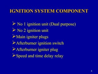
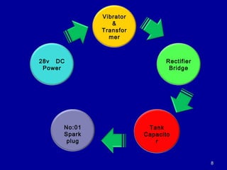
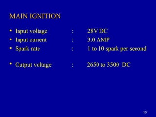
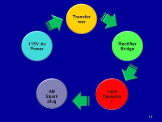
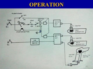
SlideShare a Scribd company logo
KFIR AIRCRAFTKFIR AIRCRAFT
IGNITION SYSTEMIGNITION SYSTEM
OBJECTIVE
At the end of this Lesson to make you all
aware,
a. Purpose and principle of
ignition system.
b. Construction and operation of
ignition system of kfir aircraft.
3
LESSON COVERAGELESSON COVERAGE
Introduction.
System components.
No 1 ignition unit
No 2 ignition unit
A/B ignition switch
A/B igniter plug
Speed and time delay relay
Operation
Conclusion.
Question. 33
INTRODUCTIONINTRODUCTION
The ignition system comprise three separate
circuits and 2 ignition units, one of which is a dual
purpose unit. All three circuits are independent in
operation except that the No 1 and No 2 main circuits
operate together with the actuation of a single switch.
The A/B circuit is mounted within the No 1 ignition unit
and is operated by a fuel pressure signal.
Cont…
The system incorporates two identical igniter
units and 2 igniters installed in combustion chamber.
The igniter units convert 28 V DC power from DC 1-
1 bus into high voltage pulses. Igniter unit No 1 also
supplies ignition pulses to the A/B ignition torch
through AC -2 bus
55
Cont…
IGNITION SYSTEM COMPONENTIGNITION SYSTEM COMPONENT
 No 1 ignition unit (Dual purpose)
 No 2 ignition unit
Main igniter plugs
Afterburner ignition switch
Afterburner igniter plug
Speed and time delay relay
66
NO 1 IGNITION UNITNO 1 IGNITION UNIT
The ignition unit changes the 28 V DC power into
periodic high energy electrical pulses necessary for
main igniter plug operation. It also changes the 115 V
400 cycle AC A/C power into periodic high energy
electrical pulses for A/B igniter plug operation .
77
88
28v DC
Power
Vibrator
&
Transfor
mer
Rectifier
Bridge
Tank
Capacito
r
No:01
Spark
plug
99
MAIN IGNITIONMAIN IGNITION
• Input voltage : 28V DC
• Input current : 3.0 AMP
• Spark rate : 1 to 10 spark per second
• Output voltage : 2650 to 3500 DC
1010
• Input voltage : 115V AC 400 cycle
• Input current : 0.5 AMP
• Spark rate : 4 spark per second
• Output voltage : 2650 to 3500 DC
AFTERBURNER IGNITIONAFTERBURNER IGNITION
1111
NO: 2 IGNITION UNITNO: 2 IGNITION UNIT
The ignition unit increases the 28 V DC aircraft
power into periodic high energy electrical pulses
necessary for ,main igniter plug operation. This unit
operates in conjunction with the main circuit of the
No 1 ignition unit.
1212
1313
AFTER BURNER IGNITION SWITCHAFTER BURNER IGNITION SWITCH
The afterburner ignition switch permits the flowThe afterburner ignition switch permits the flow
of current from an aircraft power source to theof current from an aircraft power source to the
afterburner ignition circuit of the ignition unit duringafterburner ignition circuit of the ignition unit during
afterburner operation.afterburner operation.
1414
AFTERBURNER IGNITER PLUGAFTERBURNER IGNITER PLUG
The afterburner igniter plug produces the sparkThe afterburner igniter plug produces the spark
that ignites the fuel air mixture inthat ignites the fuel air mixture in the torch igniterthe torch igniter
for afterburner operation.for afterburner operation.
1515
1616
1717
115V Ac
Power
Transfor
mer
Rectifier
Bridge
Tank
Capacito
r
AB
Spark
plug
1818
1919
2020
SPEED AND TIME DELAY RELAYSPEED AND TIME DELAY RELAY
 At 40% RPM de-energizes the starting relay, ignition
stops and the engine accelerates on its own.
 60 seconds after depressing the STARTER push
button , de energizes the ignition relay and starting
relay if not de energized at 40%RPM.
2121
At 40% RPM
After 60
seconds
de energizes
the ignition
relay and
ignition stops
OPERATIONOPERATION
2222
2323
2424
2525
2626
STARTING AND IGNITION SYSTEM
Once the fuel valve is open and LP pump are on
signal the ground crew to supply the air pressure for
start . when RPM is alive depress the STARTER push
button . at 10% RPM the pilot opens the throttle to idle ,
the ignition units starts to operate and fuel is supplied to
the engine . at 35% signal to the ground crew to stop air
pressure . the engine continues to accelerate and stabilizes
at 66%- 68% RPM.
OPERATION
NORMAL OPERATION
When the ignition switch is closed, 28 V DC current flows to both
main ignition units. here it is converted to AC, increased in
amplitude, and rectified to DC to charge the tank capacitor. The
tank capacitor discharges when voltage becomes high enough to
ionize the sealed gap. The discharge passes through the igniter
plug lead, a heavily insulated cable, to the igniter plug. A semi-
conducting material shunts the igniter plug electrodes. When the
voltage between the electrodes reaches approximately 1000 volt
current flows across the surface of semi-conductor and ionizes the
air gap between the electrodes, permitting the tank capacitor to
discharge completely. The periodic high-intensity sparks initiate
combustion .
2727
AFTERBERNER SYSTEMAFTERBERNER SYSTEM
When the afterburner ignition switch contacts close, currentWhen the afterburner ignition switch contacts close, current
passes from the aircraft 115v ac power source to the afterburnerpasses from the aircraft 115v ac power source to the afterburner
ignition circuit of the no:01 ignition unit. The ignition circuitignition circuit of the no:01 ignition unit. The ignition circuit
increases the applied voltage in amplitude and rectifies it.Theincreases the applied voltage in amplitude and rectifies it.The
direct current charges a tank capacitor within the ignitiondirect current charges a tank capacitor within the ignition
subsystem. Normally a potential of 1000-1500 volts between thesubsystem. Normally a potential of 1000-1500 volts between the
igniter plug electrodes is sufficient to ionize the air gap. Theigniter plug electrodes is sufficient to ionize the air gap. The
discharge produces the spark that ignites the fuel-air mixturedischarge produces the spark that ignites the fuel-air mixture
within the torch igniter. The flame from the torch igniter thenwithin the torch igniter. The flame from the torch igniter then
ignites the fuel-air mixture within the tailpipe. The afterburnerignites the fuel-air mixture within the tailpipe. The afterburner
ignition system functions continuously during afterburnerignition system functions continuously during afterburner
operation.operation.
2828
AIR RE-IGNITIONAIR RE-IGNITION
When the engine failure occurs during flight,When the engine failure occurs during flight,
pilot desires to re-ignite the engine.when re-light switchpilot desires to re-ignite the engine.when re-light switch
put to forward position,both main igniter plugs areput to forward position,both main igniter plugs are
directly powered through the DC 1-1 bus and igniterdirectly powered through the DC 1-1 bus and igniter
plugs continuously operate until re-light switch onplugs continuously operate until re-light switch on
forward position.forward position.
2929
3030
CONCLUSIONCONCLUSION..
Introduction of ignition system.Introduction of ignition system.
Description of ignition system.Description of ignition system.
Ignition system component.Ignition system component.
Description of component.Description of component.
3131
REFERENCEREFERENCE
• Aircraft maintenance manualAircraft maintenance manual
3232
3434

More Related Content

What's hot

Propulsion control system
Propulsion control systemPropulsion control system
Propulsion control system
MilindPatil136
 
Aircraft instruments
Aircraft instrumentsAircraft instruments
Aircraft instruments
Kamaraja AS
 
Aircraft cabin pressurization system
Aircraft  cabin pressurization systemAircraft  cabin pressurization system
Aircraft cabin pressurization system
Shrinivas Kale
 
Electronic fuel injection
Electronic fuel injectionElectronic fuel injection
Electronic fuel injection
Saqlain Ahmed
 
Aircraft cabin pressurization system
Aircraft cabin pressurization systemAircraft cabin pressurization system
Aircraft cabin pressurization system
Shrinivas Kale
 
Chapter 56
Chapter 56Chapter 56
Chapter 56
mcfalltj
 
Mpfi engine
Mpfi engineMpfi engine
Mpfi engine
maheshwarai
 
Combustion chambers-and-performance
Combustion chambers-and-performanceCombustion chambers-and-performance
Combustion chambers-and-performance
manojg1990
 
STEAM AND GAS TURBINES ppt
STEAM AND GAS TURBINES pptSTEAM AND GAS TURBINES ppt
STEAM AND GAS TURBINES ppt
ANKIT GUPTA
 
Aircraft hydraulic systems
Aircraft hydraulic systemsAircraft hydraulic systems
Aircraft hydraulic systems
Ys Prasanna
 
Compressors - Training sessions
Compressors - Training sessionsCompressors - Training sessions
Compressors - Training sessions
Nathan
 
Aircraft fuel system.pptx manhar singh
Aircraft fuel system.pptx    manhar singhAircraft fuel system.pptx    manhar singh
Aircraft fuel system.pptx manhar singh
fiyghar.com
 
The engineer’s licensing guidance document ELGD 2007
The engineer’s licensing guidance document ELGD 2007The engineer’s licensing guidance document ELGD 2007
The engineer’s licensing guidance document ELGD 2007
International Society for Licensed Aircraft Maintenance Engineers
 
Aerodynamics
AerodynamicsAerodynamics
Aerodynamics
abhishek singh yadav
 
Fuel injectors
Fuel injectorsFuel injectors
Fuel injectors
Pushpajeet .
 
Aircraft and engine fuel system and engine lubrication system
Aircraft  and engine fuel system and engine lubrication systemAircraft  and engine fuel system and engine lubrication system
Aircraft and engine fuel system and engine lubrication system
Sanjay Singh
 
Automotive battery
Automotive batteryAutomotive battery
Automotive battery
Jayanth Joseph
 
Aircraft mechanical cable control system
Aircraft mechanical cable control systemAircraft mechanical cable control system
Aircraft mechanical cable control system
raj_sevak
 
Engine electrical systems
Engine electrical systemsEngine electrical systems
Engine electrical systems
Craig Kielb
 
Piston Engines: Operation
Piston Engines: OperationPiston Engines: Operation
Piston Engines: Operation
Jess Peters
 

What's hot (20)

Propulsion control system
Propulsion control systemPropulsion control system
Propulsion control system
 
Aircraft instruments
Aircraft instrumentsAircraft instruments
Aircraft instruments
 
Aircraft cabin pressurization system
Aircraft  cabin pressurization systemAircraft  cabin pressurization system
Aircraft cabin pressurization system
 
Electronic fuel injection
Electronic fuel injectionElectronic fuel injection
Electronic fuel injection
 
Aircraft cabin pressurization system
Aircraft cabin pressurization systemAircraft cabin pressurization system
Aircraft cabin pressurization system
 
Chapter 56
Chapter 56Chapter 56
Chapter 56
 
Mpfi engine
Mpfi engineMpfi engine
Mpfi engine
 
Combustion chambers-and-performance
Combustion chambers-and-performanceCombustion chambers-and-performance
Combustion chambers-and-performance
 
STEAM AND GAS TURBINES ppt
STEAM AND GAS TURBINES pptSTEAM AND GAS TURBINES ppt
STEAM AND GAS TURBINES ppt
 
Aircraft hydraulic systems
Aircraft hydraulic systemsAircraft hydraulic systems
Aircraft hydraulic systems
 
Compressors - Training sessions
Compressors - Training sessionsCompressors - Training sessions
Compressors - Training sessions
 
Aircraft fuel system.pptx manhar singh
Aircraft fuel system.pptx    manhar singhAircraft fuel system.pptx    manhar singh
Aircraft fuel system.pptx manhar singh
 
The engineer’s licensing guidance document ELGD 2007
The engineer’s licensing guidance document ELGD 2007The engineer’s licensing guidance document ELGD 2007
The engineer’s licensing guidance document ELGD 2007
 
Aerodynamics
AerodynamicsAerodynamics
Aerodynamics
 
Fuel injectors
Fuel injectorsFuel injectors
Fuel injectors
 
Aircraft and engine fuel system and engine lubrication system
Aircraft  and engine fuel system and engine lubrication systemAircraft  and engine fuel system and engine lubrication system
Aircraft and engine fuel system and engine lubrication system
 
Automotive battery
Automotive batteryAutomotive battery
Automotive battery
 
Aircraft mechanical cable control system
Aircraft mechanical cable control systemAircraft mechanical cable control system
Aircraft mechanical cable control system
 
Engine electrical systems
Engine electrical systemsEngine electrical systems
Engine electrical systems
 
Piston Engines: Operation
Piston Engines: OperationPiston Engines: Operation
Piston Engines: Operation
 

Similar to Aircraft Ignaition System

ignition system
ignition systemignition system
ignition system
Ajeet Kumar
 
Ignitions neeroz
Ignitions neerozIgnitions neeroz
Ignitions neeroz
Niraj Adhikari
 
Ignition system
Ignition systemIgnition system
Ignition system
munir sharif
 
Gas Turbine Power Plant.pdf
Gas Turbine Power Plant.pdfGas Turbine Power Plant.pdf
Gas Turbine Power Plant.pdf
KIET Group of Institutions
 
Internal combustion engines Systems
Internal combustion engines SystemsInternal combustion engines Systems
Internal combustion engines Systems
Rushikesh Rohamare
 
Engine systems & components
Engine systems & componentsEngine systems & components
Engine systems & components
BGMEA University of Fashion & Technology
 
Ignition system
Ignition systemIgnition system
Ignition system
sauravsaxena3
 
IGNITION SYSTEM OF SI ENGINE
IGNITION SYSTEM OF SI ENGINEIGNITION SYSTEM OF SI ENGINE
IGNITION SYSTEM OF SI ENGINE
Mubassir Ghoniya
 
Electronic Ignition.pptx
Electronic Ignition.pptxElectronic Ignition.pptx
Electronic Ignition.pptx
AbhishekChavan77
 
V.T ppt
V.T pptV.T ppt
V.T ppt
Aditi Tiwari
 
Prashant report final NTPC ANTA
Prashant report final NTPC ANTAPrashant report final NTPC ANTA
Prashant report final NTPC ANTA
prashant shukla
 
POWER PLANT.pdf
POWER PLANT.pdfPOWER PLANT.pdf
POWER PLANT.pdf
MishraAnup1
 
Presentation 1 (2).pptx
Presentation 1 (2).pptxPresentation 1 (2).pptx
Presentation 1 (2).pptx
NaveenJarwal1
 
Unit 4(ICE &GT)ignition system.pptx
Unit 4(ICE &GT)ignition system.pptxUnit 4(ICE &GT)ignition system.pptx
Unit 4(ICE &GT)ignition system.pptx
ChandreshTripathi6
 
A high-frequency induction heating system feed from parallel connected cascad...
A high-frequency induction heating system feed from parallel connected cascad...A high-frequency induction heating system feed from parallel connected cascad...
A high-frequency induction heating system feed from parallel connected cascad...
MahmoudAboelnaga12
 
A high-frequency induction heating system feed from parallel connected cascad...
A high-frequency induction heating system feed from parallel connected cascad...A high-frequency induction heating system feed from parallel connected cascad...
A high-frequency induction heating system feed from parallel connected cascad...
MahmoudAboelnaga12
 
Ice handout Spark ignition by Muhammad Zubair Qureshi
Ice handout Spark ignition by Muhammad Zubair QureshiIce handout Spark ignition by Muhammad Zubair Qureshi
Ice handout Spark ignition by Muhammad Zubair Qureshi
UET Lahore
 
216190 130120119094 111_114
216190 130120119094 111_114216190 130120119094 111_114
216190 130120119094 111_114
Darshit Panchal
 
ignition system
ignition systemignition system
ignition system
Mr. Mrunal Raut
 
aircraft ignition system.ppt
aircraft ignition system.pptaircraft ignition system.ppt
aircraft ignition system.ppt
MoezzAsifResearchAss
 

Similar to Aircraft Ignaition System (20)

ignition system
ignition systemignition system
ignition system
 
Ignitions neeroz
Ignitions neerozIgnitions neeroz
Ignitions neeroz
 
Ignition system
Ignition systemIgnition system
Ignition system
 
Gas Turbine Power Plant.pdf
Gas Turbine Power Plant.pdfGas Turbine Power Plant.pdf
Gas Turbine Power Plant.pdf
 
Internal combustion engines Systems
Internal combustion engines SystemsInternal combustion engines Systems
Internal combustion engines Systems
 
Engine systems & components
Engine systems & componentsEngine systems & components
Engine systems & components
 
Ignition system
Ignition systemIgnition system
Ignition system
 
IGNITION SYSTEM OF SI ENGINE
IGNITION SYSTEM OF SI ENGINEIGNITION SYSTEM OF SI ENGINE
IGNITION SYSTEM OF SI ENGINE
 
Electronic Ignition.pptx
Electronic Ignition.pptxElectronic Ignition.pptx
Electronic Ignition.pptx
 
V.T ppt
V.T pptV.T ppt
V.T ppt
 
Prashant report final NTPC ANTA
Prashant report final NTPC ANTAPrashant report final NTPC ANTA
Prashant report final NTPC ANTA
 
POWER PLANT.pdf
POWER PLANT.pdfPOWER PLANT.pdf
POWER PLANT.pdf
 
Presentation 1 (2).pptx
Presentation 1 (2).pptxPresentation 1 (2).pptx
Presentation 1 (2).pptx
 
Unit 4(ICE &GT)ignition system.pptx
Unit 4(ICE &GT)ignition system.pptxUnit 4(ICE &GT)ignition system.pptx
Unit 4(ICE &GT)ignition system.pptx
 
A high-frequency induction heating system feed from parallel connected cascad...
A high-frequency induction heating system feed from parallel connected cascad...A high-frequency induction heating system feed from parallel connected cascad...
A high-frequency induction heating system feed from parallel connected cascad...
 
A high-frequency induction heating system feed from parallel connected cascad...
A high-frequency induction heating system feed from parallel connected cascad...A high-frequency induction heating system feed from parallel connected cascad...
A high-frequency induction heating system feed from parallel connected cascad...
 
Ice handout Spark ignition by Muhammad Zubair Qureshi
Ice handout Spark ignition by Muhammad Zubair QureshiIce handout Spark ignition by Muhammad Zubair Qureshi
Ice handout Spark ignition by Muhammad Zubair Qureshi
 
216190 130120119094 111_114
216190 130120119094 111_114216190 130120119094 111_114
216190 130120119094 111_114
 
ignition system
ignition systemignition system
ignition system
 
aircraft ignition system.ppt
aircraft ignition system.pptaircraft ignition system.ppt
aircraft ignition system.ppt
 

Recently uploaded

SCALING OF MOS CIRCUITS m .pptx
SCALING OF MOS CIRCUITS m                 .pptxSCALING OF MOS CIRCUITS m                 .pptx
SCALING OF MOS CIRCUITS m .pptx
harshapolam10
 
Null Bangalore | Pentesters Approach to AWS IAM
Null Bangalore | Pentesters Approach to AWS IAMNull Bangalore | Pentesters Approach to AWS IAM
Null Bangalore | Pentesters Approach to AWS IAM
Divyanshu
 
Applications of artificial Intelligence in Mechanical Engineering.pdf
Applications of artificial Intelligence in Mechanical Engineering.pdfApplications of artificial Intelligence in Mechanical Engineering.pdf
Applications of artificial Intelligence in Mechanical Engineering.pdf
Atif Razi
 
Data Driven Maintenance | UReason Webinar
Data Driven Maintenance | UReason WebinarData Driven Maintenance | UReason Webinar
Data Driven Maintenance | UReason Webinar
UReason
 
IEEE Aerospace and Electronic Systems Society as a Graduate Student Member
IEEE Aerospace and Electronic Systems Society as a Graduate Student MemberIEEE Aerospace and Electronic Systems Society as a Graduate Student Member
IEEE Aerospace and Electronic Systems Society as a Graduate Student Member
VICTOR MAESTRE RAMIREZ
 
VARIABLE FREQUENCY DRIVE. VFDs are widely used in industrial applications for...
VARIABLE FREQUENCY DRIVE. VFDs are widely used in industrial applications for...VARIABLE FREQUENCY DRIVE. VFDs are widely used in industrial applications for...
VARIABLE FREQUENCY DRIVE. VFDs are widely used in industrial applications for...
PIMR BHOPAL
 
Welding Metallurgy Ferrous Materials.pdf
Welding Metallurgy Ferrous Materials.pdfWelding Metallurgy Ferrous Materials.pdf
Welding Metallurgy Ferrous Materials.pdf
AjmalKhan50578
 
学校原版美国波士顿大学毕业证学历学位证书原版一模一样
学校原版美国波士顿大学毕业证学历学位证书原版一模一样学校原版美国波士顿大学毕业证学历学位证书原版一模一样
学校原版美国波士顿大学毕业证学历学位证书原版一模一样
171ticu
 
4. Mosca vol I -Fisica-Tipler-5ta-Edicion-Vol-1.pdf
4. Mosca vol I -Fisica-Tipler-5ta-Edicion-Vol-1.pdf4. Mosca vol I -Fisica-Tipler-5ta-Edicion-Vol-1.pdf
4. Mosca vol I -Fisica-Tipler-5ta-Edicion-Vol-1.pdf
Gino153088
 
Redefining brain tumor segmentation: a cutting-edge convolutional neural netw...
Redefining brain tumor segmentation: a cutting-edge convolutional neural netw...Redefining brain tumor segmentation: a cutting-edge convolutional neural netw...
Redefining brain tumor segmentation: a cutting-edge convolutional neural netw...
IJECEIAES
 
Software Engineering and Project Management - Software Testing + Agile Method...
Software Engineering and Project Management - Software Testing + Agile Method...Software Engineering and Project Management - Software Testing + Agile Method...
Software Engineering and Project Management - Software Testing + Agile Method...
Prakhyath Rai
 
Properties Railway Sleepers and Test.pptx
Properties Railway Sleepers and Test.pptxProperties Railway Sleepers and Test.pptx
Properties Railway Sleepers and Test.pptx
MDSABBIROJJAMANPAYEL
 
Use PyCharm for remote debugging of WSL on a Windo cf5c162d672e4e58b4dde5d797...
Use PyCharm for remote debugging of WSL on a Windo cf5c162d672e4e58b4dde5d797...Use PyCharm for remote debugging of WSL on a Windo cf5c162d672e4e58b4dde5d797...
Use PyCharm for remote debugging of WSL on a Windo cf5c162d672e4e58b4dde5d797...
shadow0702a
 
Design and optimization of ion propulsion drone
Design and optimization of ion propulsion droneDesign and optimization of ion propulsion drone
Design and optimization of ion propulsion drone
bjmsejournal
 
Mechanical Engineering on AAI Summer Training Report-003.pdf
Mechanical Engineering on AAI Summer Training Report-003.pdfMechanical Engineering on AAI Summer Training Report-003.pdf
Mechanical Engineering on AAI Summer Training Report-003.pdf
21UME003TUSHARDEB
 
Digital Twins Computer Networking Paper Presentation.pptx
Digital Twins Computer Networking Paper Presentation.pptxDigital Twins Computer Networking Paper Presentation.pptx
Digital Twins Computer Networking Paper Presentation.pptx
aryanpankaj78
 
一比一原版(爱大毕业证书)爱荷华大学毕业证如何办理
一比一原版(爱大毕业证书)爱荷华大学毕业证如何办理一比一原版(爱大毕业证书)爱荷华大学毕业证如何办理
一比一原版(爱大毕业证书)爱荷华大学毕业证如何办理
nedcocy
 
一比一原版(osu毕业证书)美国俄勒冈州立大学毕业证如何办理
一比一原版(osu毕业证书)美国俄勒冈州立大学毕业证如何办理一比一原版(osu毕业证书)美国俄勒冈州立大学毕业证如何办理
一比一原版(osu毕业证书)美国俄勒冈州立大学毕业证如何办理
upoux
 
morris_worm_intro_and_source_code_analysis_.pdf
morris_worm_intro_and_source_code_analysis_.pdfmorris_worm_intro_and_source_code_analysis_.pdf
morris_worm_intro_and_source_code_analysis_.pdf
ycwu0509
 
CompEx~Manual~1210 (2).pdf COMPEX GAS AND VAPOURS
CompEx~Manual~1210 (2).pdf COMPEX GAS AND VAPOURSCompEx~Manual~1210 (2).pdf COMPEX GAS AND VAPOURS
CompEx~Manual~1210 (2).pdf COMPEX GAS AND VAPOURS
RamonNovais6
 

Recently uploaded (20)

SCALING OF MOS CIRCUITS m .pptx
SCALING OF MOS CIRCUITS m                 .pptxSCALING OF MOS CIRCUITS m                 .pptx
SCALING OF MOS CIRCUITS m .pptx
 
Null Bangalore | Pentesters Approach to AWS IAM
Null Bangalore | Pentesters Approach to AWS IAMNull Bangalore | Pentesters Approach to AWS IAM
Null Bangalore | Pentesters Approach to AWS IAM
 
Applications of artificial Intelligence in Mechanical Engineering.pdf
Applications of artificial Intelligence in Mechanical Engineering.pdfApplications of artificial Intelligence in Mechanical Engineering.pdf
Applications of artificial Intelligence in Mechanical Engineering.pdf
 
Data Driven Maintenance | UReason Webinar
Data Driven Maintenance | UReason WebinarData Driven Maintenance | UReason Webinar
Data Driven Maintenance | UReason Webinar
 
IEEE Aerospace and Electronic Systems Society as a Graduate Student Member
IEEE Aerospace and Electronic Systems Society as a Graduate Student MemberIEEE Aerospace and Electronic Systems Society as a Graduate Student Member
IEEE Aerospace and Electronic Systems Society as a Graduate Student Member
 
VARIABLE FREQUENCY DRIVE. VFDs are widely used in industrial applications for...
VARIABLE FREQUENCY DRIVE. VFDs are widely used in industrial applications for...VARIABLE FREQUENCY DRIVE. VFDs are widely used in industrial applications for...
VARIABLE FREQUENCY DRIVE. VFDs are widely used in industrial applications for...
 
Welding Metallurgy Ferrous Materials.pdf
Welding Metallurgy Ferrous Materials.pdfWelding Metallurgy Ferrous Materials.pdf
Welding Metallurgy Ferrous Materials.pdf
 
学校原版美国波士顿大学毕业证学历学位证书原版一模一样
学校原版美国波士顿大学毕业证学历学位证书原版一模一样学校原版美国波士顿大学毕业证学历学位证书原版一模一样
学校原版美国波士顿大学毕业证学历学位证书原版一模一样
 
4. Mosca vol I -Fisica-Tipler-5ta-Edicion-Vol-1.pdf
4. Mosca vol I -Fisica-Tipler-5ta-Edicion-Vol-1.pdf4. Mosca vol I -Fisica-Tipler-5ta-Edicion-Vol-1.pdf
4. Mosca vol I -Fisica-Tipler-5ta-Edicion-Vol-1.pdf
 
Redefining brain tumor segmentation: a cutting-edge convolutional neural netw...
Redefining brain tumor segmentation: a cutting-edge convolutional neural netw...Redefining brain tumor segmentation: a cutting-edge convolutional neural netw...
Redefining brain tumor segmentation: a cutting-edge convolutional neural netw...
 
Software Engineering and Project Management - Software Testing + Agile Method...
Software Engineering and Project Management - Software Testing + Agile Method...Software Engineering and Project Management - Software Testing + Agile Method...
Software Engineering and Project Management - Software Testing + Agile Method...
 
Properties Railway Sleepers and Test.pptx
Properties Railway Sleepers and Test.pptxProperties Railway Sleepers and Test.pptx
Properties Railway Sleepers and Test.pptx
 
Use PyCharm for remote debugging of WSL on a Windo cf5c162d672e4e58b4dde5d797...
Use PyCharm for remote debugging of WSL on a Windo cf5c162d672e4e58b4dde5d797...Use PyCharm for remote debugging of WSL on a Windo cf5c162d672e4e58b4dde5d797...
Use PyCharm for remote debugging of WSL on a Windo cf5c162d672e4e58b4dde5d797...
 
Design and optimization of ion propulsion drone
Design and optimization of ion propulsion droneDesign and optimization of ion propulsion drone
Design and optimization of ion propulsion drone
 
Mechanical Engineering on AAI Summer Training Report-003.pdf
Mechanical Engineering on AAI Summer Training Report-003.pdfMechanical Engineering on AAI Summer Training Report-003.pdf
Mechanical Engineering on AAI Summer Training Report-003.pdf
 
Digital Twins Computer Networking Paper Presentation.pptx
Digital Twins Computer Networking Paper Presentation.pptxDigital Twins Computer Networking Paper Presentation.pptx
Digital Twins Computer Networking Paper Presentation.pptx
 
一比一原版(爱大毕业证书)爱荷华大学毕业证如何办理
一比一原版(爱大毕业证书)爱荷华大学毕业证如何办理一比一原版(爱大毕业证书)爱荷华大学毕业证如何办理
一比一原版(爱大毕业证书)爱荷华大学毕业证如何办理
 
一比一原版(osu毕业证书)美国俄勒冈州立大学毕业证如何办理
一比一原版(osu毕业证书)美国俄勒冈州立大学毕业证如何办理一比一原版(osu毕业证书)美国俄勒冈州立大学毕业证如何办理
一比一原版(osu毕业证书)美国俄勒冈州立大学毕业证如何办理
 
morris_worm_intro_and_source_code_analysis_.pdf
morris_worm_intro_and_source_code_analysis_.pdfmorris_worm_intro_and_source_code_analysis_.pdf
morris_worm_intro_and_source_code_analysis_.pdf
 
CompEx~Manual~1210 (2).pdf COMPEX GAS AND VAPOURS
CompEx~Manual~1210 (2).pdf COMPEX GAS AND VAPOURSCompEx~Manual~1210 (2).pdf COMPEX GAS AND VAPOURS
CompEx~Manual~1210 (2).pdf COMPEX GAS AND VAPOURS
 

Aircraft Ignaition System

  • 1. KFIR AIRCRAFTKFIR AIRCRAFT IGNITION SYSTEMIGNITION SYSTEM
  • 2. OBJECTIVE At the end of this Lesson to make you all aware, a. Purpose and principle of ignition system. b. Construction and operation of ignition system of kfir aircraft. 3
  • 3. LESSON COVERAGELESSON COVERAGE Introduction. System components. No 1 ignition unit No 2 ignition unit A/B ignition switch A/B igniter plug Speed and time delay relay Operation Conclusion. Question. 33
  • 4. INTRODUCTIONINTRODUCTION The ignition system comprise three separate circuits and 2 ignition units, one of which is a dual purpose unit. All three circuits are independent in operation except that the No 1 and No 2 main circuits operate together with the actuation of a single switch. The A/B circuit is mounted within the No 1 ignition unit and is operated by a fuel pressure signal. Cont…
  • 5. The system incorporates two identical igniter units and 2 igniters installed in combustion chamber. The igniter units convert 28 V DC power from DC 1- 1 bus into high voltage pulses. Igniter unit No 1 also supplies ignition pulses to the A/B ignition torch through AC -2 bus 55 Cont…
  • 6. IGNITION SYSTEM COMPONENTIGNITION SYSTEM COMPONENT  No 1 ignition unit (Dual purpose)  No 2 ignition unit Main igniter plugs Afterburner ignition switch Afterburner igniter plug Speed and time delay relay 66
  • 7. NO 1 IGNITION UNITNO 1 IGNITION UNIT The ignition unit changes the 28 V DC power into periodic high energy electrical pulses necessary for main igniter plug operation. It also changes the 115 V 400 cycle AC A/C power into periodic high energy electrical pulses for A/B igniter plug operation . 77
  • 9. 99
  • 10. MAIN IGNITIONMAIN IGNITION • Input voltage : 28V DC • Input current : 3.0 AMP • Spark rate : 1 to 10 spark per second • Output voltage : 2650 to 3500 DC 1010
  • 11. • Input voltage : 115V AC 400 cycle • Input current : 0.5 AMP • Spark rate : 4 spark per second • Output voltage : 2650 to 3500 DC AFTERBURNER IGNITIONAFTERBURNER IGNITION 1111
  • 12. NO: 2 IGNITION UNITNO: 2 IGNITION UNIT The ignition unit increases the 28 V DC aircraft power into periodic high energy electrical pulses necessary for ,main igniter plug operation. This unit operates in conjunction with the main circuit of the No 1 ignition unit. 1212
  • 13. 1313
  • 14. AFTER BURNER IGNITION SWITCHAFTER BURNER IGNITION SWITCH The afterburner ignition switch permits the flowThe afterburner ignition switch permits the flow of current from an aircraft power source to theof current from an aircraft power source to the afterburner ignition circuit of the ignition unit duringafterburner ignition circuit of the ignition unit during afterburner operation.afterburner operation. 1414
  • 15. AFTERBURNER IGNITER PLUGAFTERBURNER IGNITER PLUG The afterburner igniter plug produces the sparkThe afterburner igniter plug produces the spark that ignites the fuel air mixture inthat ignites the fuel air mixture in the torch igniterthe torch igniter for afterburner operation.for afterburner operation. 1515
  • 16. 1616
  • 18. 1818
  • 19. 1919
  • 20. 2020 SPEED AND TIME DELAY RELAYSPEED AND TIME DELAY RELAY  At 40% RPM de-energizes the starting relay, ignition stops and the engine accelerates on its own.  60 seconds after depressing the STARTER push button , de energizes the ignition relay and starting relay if not de energized at 40%RPM.
  • 21. 2121 At 40% RPM After 60 seconds de energizes the ignition relay and ignition stops
  • 23. 2323
  • 24. 2424
  • 25. 2525
  • 26. 2626 STARTING AND IGNITION SYSTEM Once the fuel valve is open and LP pump are on signal the ground crew to supply the air pressure for start . when RPM is alive depress the STARTER push button . at 10% RPM the pilot opens the throttle to idle , the ignition units starts to operate and fuel is supplied to the engine . at 35% signal to the ground crew to stop air pressure . the engine continues to accelerate and stabilizes at 66%- 68% RPM.
  • 27. OPERATION NORMAL OPERATION When the ignition switch is closed, 28 V DC current flows to both main ignition units. here it is converted to AC, increased in amplitude, and rectified to DC to charge the tank capacitor. The tank capacitor discharges when voltage becomes high enough to ionize the sealed gap. The discharge passes through the igniter plug lead, a heavily insulated cable, to the igniter plug. A semi- conducting material shunts the igniter plug electrodes. When the voltage between the electrodes reaches approximately 1000 volt current flows across the surface of semi-conductor and ionizes the air gap between the electrodes, permitting the tank capacitor to discharge completely. The periodic high-intensity sparks initiate combustion . 2727
  • 28. AFTERBERNER SYSTEMAFTERBERNER SYSTEM When the afterburner ignition switch contacts close, currentWhen the afterburner ignition switch contacts close, current passes from the aircraft 115v ac power source to the afterburnerpasses from the aircraft 115v ac power source to the afterburner ignition circuit of the no:01 ignition unit. The ignition circuitignition circuit of the no:01 ignition unit. The ignition circuit increases the applied voltage in amplitude and rectifies it.Theincreases the applied voltage in amplitude and rectifies it.The direct current charges a tank capacitor within the ignitiondirect current charges a tank capacitor within the ignition subsystem. Normally a potential of 1000-1500 volts between thesubsystem. Normally a potential of 1000-1500 volts between the igniter plug electrodes is sufficient to ionize the air gap. Theigniter plug electrodes is sufficient to ionize the air gap. The discharge produces the spark that ignites the fuel-air mixturedischarge produces the spark that ignites the fuel-air mixture within the torch igniter. The flame from the torch igniter thenwithin the torch igniter. The flame from the torch igniter then ignites the fuel-air mixture within the tailpipe. The afterburnerignites the fuel-air mixture within the tailpipe. The afterburner ignition system functions continuously during afterburnerignition system functions continuously during afterburner operation.operation. 2828
  • 29. AIR RE-IGNITIONAIR RE-IGNITION When the engine failure occurs during flight,When the engine failure occurs during flight, pilot desires to re-ignite the engine.when re-light switchpilot desires to re-ignite the engine.when re-light switch put to forward position,both main igniter plugs areput to forward position,both main igniter plugs are directly powered through the DC 1-1 bus and igniterdirectly powered through the DC 1-1 bus and igniter plugs continuously operate until re-light switch onplugs continuously operate until re-light switch on forward position.forward position. 2929
  • 30. 3030
  • 31. CONCLUSIONCONCLUSION.. Introduction of ignition system.Introduction of ignition system. Description of ignition system.Description of ignition system. Ignition system component.Ignition system component. Description of component.Description of component. 3131
  • 32. REFERENCEREFERENCE • Aircraft maintenance manualAircraft maintenance manual 3232
  • 33.
  • 34. 3434