SlideShare a Scribd company logo
ELECTRICAL AND IGNITION


                                                  2
                                                  A


IGNITION SYSTEM


90-831996R1 JUNE 1996   ELECTRICAL AND IGNITION   2A-–1
Table Of Contents
                                                                            Page                                                                     Page
Special Tools Required . . . . . . . . . . . . . . . . . . .                2A-1   Removing Flywheel . . . . . . . . . . . . . . . . . . . . . . 2A-7
General . . . . . . . . . . . . . . . . . . . . . . . . . . . . . . . . .   2A-1   Installing Flywheel . . . . . . . . . . . . . . . . . . . . . . . . 2A-8
Principles of Operation . . . . . . . . . . . . . . . . . . . .             2A-1   Removing Stator . . . . . . . . . . . . . . . . . . . . . . . . . 2A-8
Test Procedures . . . . . . . . . . . . . . . . . . . . . . . . .           2A-1   Installing Stator . . . . . . . . . . . . . . . . . . . . . . . . . . 2A-8
Testing For Spark . . . . . . . . . . . . . . . . . . . . . . . .           2A-2   Removing Trigger . . . . . . . . . . . . . . . . . . . . . . . . 2A-8
Testing Primary Input Voltage . . . . . . . . . . . . . .                   2A-2   Installing Trigger . . . . . . . . . . . . . . . . . . . . . . . . . 2A-9
Test Switch Box “Stop” Circuit. . . . . . . . . . . . . .                   2A-3   Removing Switch Box . . . . . . . . . . . . . . . . . . . . 2A-9
Testing Stator Output . . . . . . . . . . . . . . . . . . . . .             2A-3   Installing Switch Box . . . . . . . . . . . . . . . . . . . . . . 2A-9
Testing Stator Resistance . . . . . . . . . . . . . . . . .                 2A-3   Removing Coils . . . . . . . . . . . . . . . . . . . . . . . . . 2A-10
    Testing Switch Box Bias Circuit-                                               Installing Coils . . . . . . . . . . . . . . . . . . . . . . . . . . 2A-10
        90 HP Only . . . . . . . . . . . . . . . . . . . . . . .            2A-4   Ignition Diagram 90 HP Sport Jet . . . . . . . . . . 2A-11
Testing Trigger Resistance . . . . . . . . . . . . . . . .                  2A-4   Ignition Wiring Diagram
Testing Ignition Coils . . . . . . . . . . . . . . . . . . . . . .          2A-5       120 Sport Jet . . . . . . . . . . . . . . . . . . . . . . . . 2A-12
Erratic/Misfire or No Fire Condition . . . . . . . . .                      2A-6


2A-0                                                              ELECTRICAL AND IGNITION                                  90-831996R1 JUNE 1996
The stator assembly is mounted stationary below the
Special Tools Required                                      flywheel and has two capacitor charging coils. The fly-
Multimeter/ DVA Tester 91-99750                             wheel is fitted with permanent magnets inside the out-
                                                            er rim. As the flywheel rotates the permanent mag-
                                                            nets pass the capacitor charging coils. This causes
                                                            the capacitor charging coils to produce AC voltage.
                                                            The AC voltage then is conducted to the switch box
                                                            where it is rectified and stored in a capacitor.
                                                            The trigger assembly (also mounted under the fly-
                                                            wheel) has 2 coils. The flywheel likewise has a sec-
                                                            ond set of permanent magnets (located around the
                                                            center hub). As the flywheel rotates the second set of
                                                            magnets pass the trigger coils. This causes the trig-
                                                            ger coils, in turn, to produce an AC voltage that is con-
                                                            ducted to an electronic switch (SCR) in the switch
Spark Tester 91-850439                                      box.
                                                            The switch discharges the capacitor voltage into the
                                                            primary side of the ignition coil.
                                                            The ignition coil multiplies this voltage to a value high
                                                            enough to jump the gap at the spark plug.
                                                            The preceding sequence occurs once per engine rev-
                                                            olution for each cylinder.
                                                            Spark timing is changed (advanced/retarded) by ro-
                                                            tating the trigger assembly which changes each trig-
                                                            ger coil position in relation to the permanent magnets
                                            55117
                                                            on the flywheel hub.

General                                                     Test Procedures
The ignition system used on the Sport Jet engines is
self-energizing (creates it’s own power for ignition)                              WARNING
and has proven reliability. Should testing be required      When testing or servicing the ignition system
it is important to check all components in the order        high voltage is present. Be extremely cautious!
outlined.                                                   DO NOT TOUCH OR DISCONNECT any ignition
                                                            parts while engine is running, while key switch is
IMPORTANT: Read the entire procedure before at-
                                                            on, or while battery cables are connected.
tempting to test components.
The procedures in this section are designed to test
the complete ignition system. In an actual situation                               CAUTION
test only the components that control the misfiring cyl-    Failure to comply with the following items may
inder(s).                                                   result in damage to the ignition system.
                                                            S   DO NOT reverse battery cable connections. The
                       WARNING                                  battery negative cable is (–) ground. DO NOT
When testing or servicing the ignition system                   “spark” battery terminals with battery cable con-
high voltage is present; be extremely cautious!                 nections to check polarity.
DO NOT TOUCH OR DISCONNECT any ignition                     S   DO NOT disconnect battery cables while engine
components while engine is cranking or running.                 is running.
Principles of Operation                                     S   DO NOT crank engine when switch box is not
                                                                grounded to engine.
The ignition system is alternator driven with distribu-
                                                            The switch box cannot be thoroughly checked with
torless capacitor discharge. Major components of the
                                                            conventional test equipment. If a Multimeter/DVA
ignition system are the flywheel, stator, trigger, switch
                                                            Tester is not used systematically check the switch
box, ignition coils and spark plugs.
                                                            box.
90-831996R1 JUNE 1996                        ELECTRICAL AND IGNITION                                            2A-1
All other components can be tested with an ohmme-          Check that safety stop switch lanyard is in place. If
ter. Before troubleshooting the ignition system:           safety lanyard is NOT in place, spark plugs will not
S      Make sure the electrical harness and ignition
                                                           fire.
       switch are not the source of the problem.           9.   Isolate the stop circuit by disconnecting black/
S      Check that plug-in connectors are fully engaged          yellow bullet connector from the switch box.
       and terminals are free of corrosion.                IMPORTANT: Be sure this lead is not grounded.
S      Make sure that wire connections are tight and       10. Crank motor.
       free of corrosion.
                                                                    Results:                 Action Required:
S      Check that all electrical components and sepa-
                                                           All cylinders spark nor-    Repair stop circuit:igni-
       rate ground wires are grounded directly to en-
                                                           mally                       tion key switch and/or
       gine.
                                                                                       boat wiring.
S      Check for disconnected wires, short and open        No spark                    Go to next step
       circuits.

Testing For Spark                                          Testing Primary Input Voltage
1.     Adjust spark tester to a 7/16” gap setting.         1.   Prepare multimeter.
                                                           S    Plug meter leads in as shown.
                                                           S    Set dial to 400 DVA scale.


                                             7/16 in.


                                                           2.   Connect red meter lead to #1 coil (+) terminal.
2.     Secure spark tester to a good engine ground.        3.   Connect black meter lead to #1 coil (–) terminal.
3.     Remove leads from spark plugs.
4.     Connect spark plug leads to corresponding spark
       tester leads.
5.     Remove spark plugs.
Engine must be able to crank at 600 RPM minimum
for the following tests.
6.     Crank motor.
           Results:               Action Required:
Spark jumps 7/16 in.           Ignition system is opera-   4.   Crank motor and observe meter.
gap (all cylinders)            tional, check timing se-    5.   Repeat test for each coil.
                               quence if required
                                                           IMPORTANT: DO NOT use a common ground.
No spark                       Go to next step             Connect black meter lead to the ground of coil
7.     Check all grounds and wire connections.             being tested.
Repair as needed.                                                 Results:           Action Required:

8.     Recheck spark output.                               150 - 250 volts             Go to Testing Coils
                                                           Less than 150 volts         Go to Next Step


2A-2                                         ELECTRICAL AND IGNITION                    90-831996R1 JUNE 1996
Test Switch Box “Stop”                                  2.   Crank motor while reading meter.
                                                                            90 and 120 HP
Circuit.                                                         Results:              Action Required:
1.   Prepare multimeter as shown.                       200-300 volts               Low speed stator is
                                                                                    O.K.: Go to Testing Trig-
                                             RED                                    ger
                                             METER
                                             LEAD       Less than 200 volts or      Go to next step. If stator
                                                        intermittent                tests O.K., replace
                                                                                    switch box.
                                                        3.   Stator high-speed input to switch box.
                                                        S    Connect red meter lead to red stator lead.
                                                        S    Connect black meter lead to a good ground.
                                                        S    Set meter to 400 DVA scale.
                                                        4.   Crank motor while reading meter.
S    Disconnect black/yellow lead form switch box.
                                                                            90 and 120 HP
S    Attach red meter lead to black/yellow lead from
     switch box.                                                 Results:              Action Required:
                                                        20-90 volts               High speed stator is
S    Attach black meter lead to ground.
                                                                                  O.K.: Go to Testing Trig-
2.   Crank motor and observe meter.                                               ger.
                                                        Less than 20 volts or in- Go to next step
                                                        termittent

                                                        Testing Stator Resistance
                                                        1.   Prepare multimeter (Special Tool No. 91-99750).


         Results:              Action Required:
200-360 volts              Go to Testing Trigger. If
                           checks O.K., replace
                           switch box.
Less than 200 volts        Go to next step
                                                        S    Plug in meter leads as shown.
Testing Stator Output                                   S    Set dial to X1K ohm position.
IMPORTANT: All leads must remain connected to
                                                        S    Calibrate meter.
the switch box for the following DVA tests.
                                                        2.   Low speed resistance test.
1.   Stator low speed input to switch box.
                                                        NOTE: This test is not polarity sensitive.
S    Connect red meter lead to blue lead from stator.
S    Connect black meter lead to a good engine
     ground.
S    Set meter to 400 DVA scale.


90-831996R1 JUNE 1996                     ELECTRICAL AND IGNITION                                         2A-3
90 HP:                                                    Testing Switch Box Bias Circuit-
S      Disconnect blue and red stator leads from switch   90 HP Only
       box.
                                                          1.   Prepare multimeter as shown.
S      Connect meter leads between blue and red sta-
       tor leads.
            Results:           Action Required:
3600 - 4200* ohms            Go to next test
Above or below               Replace stator
3600 - 4200 ohms
*Copper is an excellent conductor, but resistance
may notably vary between low and high temperature.
Therefore, reasonable differences can be accepted
between resistance readings and specifications.
120 HP:
                                                                 BLACK            20 DCV           RED
S      Disconnect blue and blue/white stator leads from          METER            SCALE           METER
       switch box.                                                LEAD                            LEAD
S      Connect meter leads between blue and blue/         NOTE: White/black lead must remain connected to
       white stator leads.                                switch box for this test.
3.     Observe meter reading.                             S    Attach Black meter lead to white/black lead from
           Results:              Action Required:              switch box.
6800 - 7600* ohms            Go to next test              S    Attach Red meter lead to ground.
Above or below               Replace stator               2.   Crank motor and observe meter reading.
6800 - 7600 ohms                                                   Results:                Action Required:
*Copper is an excellent conductor, but resistance         2 - 10 volts                 Go to testing Trigger. If
may notably vary between low and high temperature.                                     trigger tests O.K. re-
Therefore, reasonable differences can be accepted                                      place switch box.
between resistance readings and specifications.           Below 2 volts                Replace switch box.
4.     High speed resistance test.
S      Set meter scale to X1 ohm.                         Testing Trigger Resistance
90 HP:                                                    1.   Prepare multimeter.
S      Disconnect red stator lead from switch box.        S    Plug meter leads in as shown.
S      Connect meter leads between red and engine         S    Set dial to x100 ohm.
       ground (if stator has been removed from engine
       connect meter leads between red stator lead and    S    Calibrate meter.
       stator ground).
120 HP:
S      Disconnect red and red/white stator leads from
       switch box.
S      Connect meter between red stator lead and red/
       white stator leads.
5.     Observe meter reading.
           Results:              Action Required:
90 - 140 ohms                Stator O.K., continue
                             electrical testing
Above or below 90 - 140 Replace stator
ohms

2A-4                                        ELECTRICAL AND IGNITION                     90-831996R1 JUNE 1996
2.   Disconnect trigger leads. Test resistance be-
     tween trigger leads as shown in the following
     chart.
This test is not polarity sensitive.
                         90 HP
       Meter Leads                  Meter Reading
Between Brown and
White/Black
Between White and                1100 - 1400 Oh
                                             Ohms
White/Black
Between Violet and
White/Black
                                                         S    Red meter lead to #1 coil (+) terminal.
                        120 HP
                                                         S    Black meter lead to #1 coil (–) terminal.
       Meter Leads                  Meter Reading
                                                         This test is not polarity sensitive.
Between Violet and
White                                                    3.   Observe meter.
Between Brown and                700 - 1000 Oh
                                            Ohms                   Results:                    Action Required:
White/Black                                               .02 - .04* ohms                  Go to next step
*Copper is an excellent conductor, but resistance         Above or below .02 - .04 Replace coil
may notably vary between low and high temperature.        ohms
Therefore, reasonable differences can be accepted         *The primary DC resistance of these coils generally is less
between resistance readings and specifications.           than one ohm. If a reading resembling a short is obtained, this
                                                          would be acceptable.
3.   Replace trigger as necessary.
                                                         4.   Repeat test for each coil.
                                                         5.   Check secondary resistance.
Testing Ignition Coils                                   S    Remove spark plug wire from coil tower.
1.   Check primary resistance.                           S    Set dial to X100 scale.
                                                         S    Calibrate meter.


S    Prepare multimeter as shown.
S    Set dial to X1 scale.
S    Calibrate meter
S    Disconnect coil input leads.
2.   Connect meter leads.


90-831996R1 JUNE 1996                       ELECTRICAL AND IGNITION                                                  2A-5
S      Connect meter leads between coil tower and coil
       positive (+) terminal.
                                                                    Erratic/Misfire or No Fire
                                                                    Condition
                                                                    Occasionally a problem may occur that will not show
                                                                    when testing at cranking speed. Some tests can be
                                                                    performed with the engine running at the particular
                                                                    RPM when the problem occurs.
                                                                    “Running” tests use the same procedures as “crank-
                                                                    ing” tests. Refer to the chart following for running test
                                                                    readings.


S      Observe meter reading.
            Results:              Action Required:
 800 - 1100*                   Go to next section
 Above or below 800 -          Replace coil
 1100 ohms
*Copper is an excellent conductor, but resistance
may notably vary between low and high temperature.
Therefore, reasonable differences can be accepted
between resistance readings and specifications.


          Test         Selector                      DVA Leads                      Voltage Reading      Voltage Reading
                       Position           Red               Black                  @ 300-1000 RPM(1)     @ 1000-4000 RPM
          Coil                            Coil (+)               Coil (–)
        Primary        400VDC*           Terminal               Terminal                150-250               180-280
        Sw. Box -                     Black/Yellow
       Stop circuit    400VDC*      Sw. Box Connector           Ground                  200-360               200-360
         Stator -                       Blue Sw.
       Low Speed       400VDC*        Box Connector             Ground                  200-300               200-330
         Stator -                       Red Sw.
       High Speed      400VDC*        Box Connector             Ground                   20-90                130-300
*If using a meter with a built-in DVA, place selector in the DVA/400 VDC position.
(1)Readings at cranking speed and/or idle speed.


2A-6                                            ELECTRICAL AND IGNITION                           90-831996R1 JUNE 1996
Removing Flywheel                                                                 CAUTION
                       WARNING                           Do not strike the screw too hard. This may
                                                         damage the crankshaft and bearings.
Always disconnect battery and remove spark
plug leads from spark plugs before working on            4.   Strike top of pressure screw (a) with hammer.
motor.
1.   Remove flywheel nut.


                                                                                              a


                                                         5.   Remove flywheel from crankshaft.
Use a suitable flywheel holder to keep flywheel from
turning.
2.   Install puller (Special Tool No. FT-8948-1).


                                                         6.   Remove puller form flywheel.
                                                         7.   Remove flywheel key.
Perform the following step while holding the puller
bar. This will prevent the puller plate from turning.
3.   Turn pressure screw until it is tight against the
                                                                       a
     crankshaft.


               a

                                                         a - Flywheel Key

                                                         8.   Inspect flywheel.
                                                         S    Carefully inspect flywheel for cracks or damage.

                                                                                  WARNING
                                                         A cracked or chipped flywheel must be replaced.
a - Pressure Screw                                       At high RPM a damaged flywheel may fly apart and
                                                         throw metal over a large area.
                                                         S    Inspect crankshaft and flywheel tapers for worn
                                                              or damaged key ways.

90-831996R1 JUNE 1996                      ELECTRICAL AND IGNITION                                       2A-7
S      Check for loose magnet or damaged timing mag-        4.   Remove screws and lift stator off bearing cage.
       net laminations.
Arc burns on timing magnet laminations are normal.
S      Replace flywheel if necessary.                                                                a

Installing Flywheel
1.     Clean tapered surfaces of flywheel and crank-
       shaft with solvent.
                                                                            a
S      Blow dry tapered surfaces with compressed air.
If the flywheel key appears damaged in any way re-
place it.
2.     Install flywheel key in crankshaft slot with outer   a - Stator Screws
       edge of key parallel to center line of crankshaft.
                                                            Installing Stator
                                                            1.   Set stator on bearing cage. Secure with screws.
                                                            IMPORTANT: Be sure the stator is positioned so
                                                            the wire harness is on the port side of the motor.
                                  a                         2.   Connect yellow stator leads to yellow rectifier/re-
                                                                 gulator leads.
                                                            3.   Connect all stator leads to corresponding switch
                                                                 box leads.
                                                            4.   Install flywheel.
a - Flywheel Key

3.     Install flywheel.
                                                            Removing Trigger
S      Place flywheel down over crankshaft.                 1.   Remove flywheel.

S      Install flywheel nut.                                SEE “REMOVING FLYWHEEL” IN THIS SECTION.

S      Torque flywheel nut to 125 lb. ft. (169.5 N·m).      2.   Remove stator.
                                                            SEE “REMOVING STATOR” IN THIS SECTION.
                                                            3.   Disconnect all trigger leads from switch box
                                                                 leads.
                                                            4.   Disconnect spark control link from tower shaft.
                                                            5.   Lift trigger off bearing cage.

                                                                        a


Removing Stator
                                                                  b
1.     Remove flywheel.
SEE “REMOVING FLYWHEEL” IN THIS SECTION.
2.     Remove yellow stator leads from rectifier/regula-
       tor leads.
3.     Disconnect all stator leads from switch box leads.
Removal of switch box mounting bracket may be nec-          a - Trigger
essary to gain access to stator leads.                      b - Spark Control Link

2A-8                                         ELECTRICAL AND IGNITION                      90-831996R1 JUNE 1996
Installing Trigger                                        Removing Switch Box
1.   Install spark control link on new trigger.
                                                                                 WARNING
                                                          Always disconnect battery and disconnect spark
                                                          plug leads from spark plugs before working on
                                                          motor.


                                         a


a - Spark Control Link

2.   Lubricate outer ring of trigger with grease.         1.   Remove three screws and clamp.
3.   Place trigger on bearing cage.                       2.   Remove switch box from bracket.
4.   Secure spark control link to towershaft.             3.   Remove lead wires from switch box.


     a
                                                                                    a

                                                                                        b

                                                          a - 90 HP Switch Box              b - 120 HP Switch Box

                                                          Installing Switch Box
a - Towershaft
                                                          1.   Position switch box on bracket.
5.   Route lead wires under ignition harness guard
     and down to switch box.                              2.   Install screws and clamp.

6.   Connect corresponding trigger leads to switch        The clamp is attached with the lower forward mount-
     box leads:                                           ing screw.

7.   Install stator.                                      3.   Attach lead wires.

SEE INSTALLING STATOR IN THIS SECTION.                    Switch box leads are identified by color.
                                                             Stator Leads       Red, Blue, Red/White,
8.   Install flywheel.
                                                                                Blue/White
SEE INSTALLING FLYWHEEL IN THIS SECTION.                       Coil Leads       Green, Green/White,
9.   Check engine timing.                                                       Green/Red, Green/Black
SEE ENGINE TIMING IN THIS SECTION.                             Stop Lead        Black/Yellow
                                                               Trigger Leads        Brown, Violet, White, White/
                                                                                    Black


90-831996R1 JUNE 1996                        ELECTRICAL AND IGNITION                                                2A-9
Removing Coils                                        Installing Coils
                                                      1.   Attach wires to coil:
                        WARNING
                                                      S    #1 Green
Always disconnect battery and disconnect spark
plug leads from spark plugs before working on         S    #2 Green/White
motor.                                                S    #3 Green/Red
                                                      S    #4 Green/Black (120 HP)
                                                      Positive (+) terminal is down.
                                                      2.   Position coil/cover assembly on bracket.
                                                      NOTE: 90 HP shown

                                                                                         a

                                                                                             b

1.   Remove screws holding coil cover.
                                                                                                 c


                                         a
                                                      a - #1 Green Terminal
                                                      b - #2 Green/White Terminal
                                                      c - #3 Green/Red Terminal

                                                      3.   Slide coil into cover.
                                                      4.   Position coil/cover assembly on bracket.
                                                      5.   Install cover screws, tighten all fasteners.

a - Screw

2.   Remove coil/cover assembly from bracket.
3.   Remove coil input wire (+) and ground wire (–)
     from coil.
4.   Slide coil out of cover.
NOTE: Coils are serviced individually.


2A-10                                    ELECTRICAL AND IGNITION                    90-831996R1 JUNE 1996
Ignition Diagram 90 HP Sport Jet


                                                                   Temperature
                        Auto Enrichner


                                                                   Switch


                                                                                 Oil Switch
                                                                                 Low


90-831996R1 JUNE 1996                    ELECTRICAL AND IGNITION                              2A-11
Ignition Wiring Diagram
120 Sport Jet


                                                                      Temperature
                     Auto Enrichner


                                                                      Switch


                                                                                    Oil Switch
                                                                                    Low


2A-12                                 ELECTRICAL AND IGNITION   90-831996R1 JUNE 1996

More Related Content

What's hot

16 engine electrical
16 engine electrical16 engine electrical
16 engine electrical
Ruan Moura
 
11 b engine 4g9 mpi
11 b engine 4g9 mpi11 b engine 4g9 mpi
11 b engine 4g9 mpi
Ruan Moura
 
Caterpillar cat 938 g wheel loader (prefix 9hs) service repair manual (9hs000...
Caterpillar cat 938 g wheel loader (prefix 9hs) service repair manual (9hs000...Caterpillar cat 938 g wheel loader (prefix 9hs) service repair manual (9hs000...
Caterpillar cat 938 g wheel loader (prefix 9hs) service repair manual (9hs000...
fusjefjkskem
 
11 a engine 4g9 gdi
11 a engine 4g9 gdi11 a engine 4g9 gdi
11 a engine 4g9 gdi
Ruan Moura
 
Гидромоторы серий MM-MP-MR-MH M+S hydraulic
Гидромоторы серий MM-MP-MR-MH M+S hydraulicГидромоторы серий MM-MP-MR-MH M+S hydraulic
Гидромоторы серий MM-MP-MR-MH M+S hydraulic
Arve
 
4 cylinder diesel engine (1.9 l engine) VW
4 cylinder diesel engine (1.9 l engine) VW4 cylinder diesel engine (1.9 l engine) VW
4 cylinder diesel engine (1.9 l engine) VW
cerjs
 
Mercury mariner outboard 90 hp service repair manual
Mercury mariner outboard 90 hp service repair manualMercury mariner outboard 90 hp service repair manual
Mercury mariner outboard 90 hp service repair manual
ufjjjdfjkksekmme
 
94231565 torque-specs-guide
94231565 torque-specs-guide94231565 torque-specs-guide
94231565 torque-specs-guidecolorico
 
Case cx130 crawler excavator service repair manual
Case cx130 crawler excavator service repair manualCase cx130 crawler excavator service repair manual
Case cx130 crawler excavator service repair manual
ufsiekdolskek
 
Jeep liberty 2002 2005 fuel system
Jeep liberty 2002 2005 fuel systemJeep liberty 2002 2005 fuel system
Jeep liberty 2002 2005 fuel system
Jeff Sparks
 

What's hot (15)

16 engine electrical
16 engine electrical16 engine electrical
16 engine electrical
 
11 b engine 4g9 mpi
11 b engine 4g9 mpi11 b engine 4g9 mpi
11 b engine 4g9 mpi
 
95ZJ_5.PDF
95ZJ_5.PDF95ZJ_5.PDF
95ZJ_5.PDF
 
Caterpillar cat 938 g wheel loader (prefix 9hs) service repair manual (9hs000...
Caterpillar cat 938 g wheel loader (prefix 9hs) service repair manual (9hs000...Caterpillar cat 938 g wheel loader (prefix 9hs) service repair manual (9hs000...
Caterpillar cat 938 g wheel loader (prefix 9hs) service repair manual (9hs000...
 
11 a engine 4g9 gdi
11 a engine 4g9 gdi11 a engine 4g9 gdi
11 a engine 4g9 gdi
 
95ZJ_21.PDF
95ZJ_21.PDF95ZJ_21.PDF
95ZJ_21.PDF
 
95ZJ_8L.PDF
95ZJ_8L.PDF95ZJ_8L.PDF
95ZJ_8L.PDF
 
Гидромоторы серий MM-MP-MR-MH M+S hydraulic
Гидромоторы серий MM-MP-MR-MH M+S hydraulicГидромоторы серий MM-MP-MR-MH M+S hydraulic
Гидромоторы серий MM-MP-MR-MH M+S hydraulic
 
Tablas de torque
Tablas de torqueTablas de torque
Tablas de torque
 
4 cylinder diesel engine (1.9 l engine) VW
4 cylinder diesel engine (1.9 l engine) VW4 cylinder diesel engine (1.9 l engine) VW
4 cylinder diesel engine (1.9 l engine) VW
 
Mercury mariner outboard 90 hp service repair manual
Mercury mariner outboard 90 hp service repair manualMercury mariner outboard 90 hp service repair manual
Mercury mariner outboard 90 hp service repair manual
 
94231565 torque-specs-guide
94231565 torque-specs-guide94231565 torque-specs-guide
94231565 torque-specs-guide
 
Case cx130 crawler excavator service repair manual
Case cx130 crawler excavator service repair manualCase cx130 crawler excavator service repair manual
Case cx130 crawler excavator service repair manual
 
95ZJ_11.PDF
95ZJ_11.PDF95ZJ_11.PDF
95ZJ_11.PDF
 
Jeep liberty 2002 2005 fuel system
Jeep liberty 2002 2005 fuel systemJeep liberty 2002 2005 fuel system
Jeep liberty 2002 2005 fuel system
 

Similar to 2a electrical and ignition

Agn102 b
Agn102 bAgn102 b
Agn102 b
SergeyShuvalov4
 
Chapter 57
Chapter 57Chapter 57
Chapter 57mcfalltj
 
POWER DISTRIBUTION 2.docx
POWER DISTRIBUTION 2.docxPOWER DISTRIBUTION 2.docx
POWER DISTRIBUTION 2.docxJeffrey Dorsey
 
A practical primer for paralleling electric systems
A practical primer for paralleling electric systemsA practical primer for paralleling electric systems
A practical primer for paralleling electric systems
Javier Maldonado Adco
 
ABB Sami GS 501 Manual
ABB Sami GS 501 ManualABB Sami GS 501 Manual
ABB Sami GS 501 Manualalfreetti
 
LV SWITCHGEAR -Final PPT.pptx
LV SWITCHGEAR -Final PPT.pptxLV SWITCHGEAR -Final PPT.pptx
LV SWITCHGEAR -Final PPT.pptx
shivendra68
 
SMAC Actuators User Manual
SMAC Actuators User ManualSMAC Actuators User Manual
SMAC Actuators User Manual
Electromate
 
455816491-ESP-Start-up-and-operation.pdf
455816491-ESP-Start-up-and-operation.pdf455816491-ESP-Start-up-and-operation.pdf
455816491-ESP-Start-up-and-operation.pdf
ZehronChemicals
 
Relay
RelayRelay
Starting system .pdfhtdu,yjfvbnyhrdgcvhfd
Starting system .pdfhtdu,yjfvbnyhrdgcvhfdStarting system .pdfhtdu,yjfvbnyhrdgcvhfd
Starting system .pdfhtdu,yjfvbnyhrdgcvhfd
YonChhannak
 

Similar to 2a electrical and ignition (20)

Probador de alternador
Probador de alternadorProbador de alternador
Probador de alternador
 
Exj 8 b
Exj 8 bExj 8 b
Exj 8 b
 
Agn102 b
Agn102 bAgn102 b
Agn102 b
 
Chapter 57
Chapter 57Chapter 57
Chapter 57
 
Exj 8 r
Exj 8 rExj 8 r
Exj 8 r
 
95ZJ_8G.PDF
95ZJ_8G.PDF95ZJ_8G.PDF
95ZJ_8G.PDF
 
95ZJ_8A.PDF
95ZJ_8A.PDF95ZJ_8A.PDF
95ZJ_8A.PDF
 
Exj 8 g
Exj 8 gExj 8 g
Exj 8 g
 
POWER DISTRIBUTION 2.docx
POWER DISTRIBUTION 2.docxPOWER DISTRIBUTION 2.docx
POWER DISTRIBUTION 2.docx
 
A practical primer for paralleling electric systems
A practical primer for paralleling electric systemsA practical primer for paralleling electric systems
A practical primer for paralleling electric systems
 
ABB Sami GS 501 Manual
ABB Sami GS 501 ManualABB Sami GS 501 Manual
ABB Sami GS 501 Manual
 
LV SWITCHGEAR -Final PPT.pptx
LV SWITCHGEAR -Final PPT.pptxLV SWITCHGEAR -Final PPT.pptx
LV SWITCHGEAR -Final PPT.pptx
 
P 626-726 1-09
P 626-726 1-09P 626-726 1-09
P 626-726 1-09
 
Wp series manual
Wp series manualWp series manual
Wp series manual
 
SMAC Actuators User Manual
SMAC Actuators User ManualSMAC Actuators User Manual
SMAC Actuators User Manual
 
Emii
EmiiEmii
Emii
 
Ignition system
Ignition systemIgnition system
Ignition system
 
455816491-ESP-Start-up-and-operation.pdf
455816491-ESP-Start-up-and-operation.pdf455816491-ESP-Start-up-and-operation.pdf
455816491-ESP-Start-up-and-operation.pdf
 
Relay
RelayRelay
Relay
 
Starting system .pdfhtdu,yjfvbnyhrdgcvhfd
Starting system .pdfhtdu,yjfvbnyhrdgcvhfdStarting system .pdfhtdu,yjfvbnyhrdgcvhfd
Starting system .pdfhtdu,yjfvbnyhrdgcvhfd
 

Recently uploaded

Croatia vs Spain Euro 2024 Epic Showdown in the Group Stage.docx
Croatia vs Spain Euro 2024 Epic Showdown in the Group Stage.docxCroatia vs Spain Euro 2024 Epic Showdown in the Group Stage.docx
Croatia vs Spain Euro 2024 Epic Showdown in the Group Stage.docx
Eticketing.co
 
Serbia vs England Tickets: Serbia's Return to Euro Cup 2024, A Look at Key Pl...
Serbia vs England Tickets: Serbia's Return to Euro Cup 2024, A Look at Key Pl...Serbia vs England Tickets: Serbia's Return to Euro Cup 2024, A Look at Key Pl...
Serbia vs England Tickets: Serbia's Return to Euro Cup 2024, A Look at Key Pl...
Eticketing.co
 
Denmark Vs England Cole Palmer thrilled to be selected in England’s Euro Cup ...
Denmark Vs England Cole Palmer thrilled to be selected in England’s Euro Cup ...Denmark Vs England Cole Palmer thrilled to be selected in England’s Euro Cup ...
Denmark Vs England Cole Palmer thrilled to be selected in England’s Euro Cup ...
World Wide Tickets And Hospitality
 
JORNADA 10 LIGA MURO 2024BASQUETBOL1.pdf
JORNADA 10 LIGA MURO 2024BASQUETBOL1.pdfJORNADA 10 LIGA MURO 2024BASQUETBOL1.pdf
JORNADA 10 LIGA MURO 2024BASQUETBOL1.pdf
Arturo Pacheco Alvarez
 
Ukraine Vs Belgium What are the odds for Ukraine to make the Euro Cup 2024 qu...
Ukraine Vs Belgium What are the odds for Ukraine to make the Euro Cup 2024 qu...Ukraine Vs Belgium What are the odds for Ukraine to make the Euro Cup 2024 qu...
Ukraine Vs Belgium What are the odds for Ukraine to make the Euro Cup 2024 qu...
World Wide Tickets And Hospitality
 
Austria Vs France Nations to look out for at Euro Cup 2024.docx
Austria Vs France Nations to look out for at Euro Cup 2024.docxAustria Vs France Nations to look out for at Euro Cup 2024.docx
Austria Vs France Nations to look out for at Euro Cup 2024.docx
World Wide Tickets And Hospitality
 
Portugal Vs Czechia- Ronaldo feels 'proud' of new UEFA Euro 2024 record.docx
Portugal Vs Czechia- Ronaldo feels 'proud' of new UEFA Euro 2024 record.docxPortugal Vs Czechia- Ronaldo feels 'proud' of new UEFA Euro 2024 record.docx
Portugal Vs Czechia- Ronaldo feels 'proud' of new UEFA Euro 2024 record.docx
World Wide Tickets And Hospitality
 
CAA Region II Day 1 Morning Result Accra event
CAA Region II Day 1 Morning Result Accra eventCAA Region II Day 1 Morning Result Accra event
CAA Region II Day 1 Morning Result Accra event
Kweku Zurek
 
Turkey vs Georgia Turkey's Road to Redemption and Euro 2024 Prospects.pdf
Turkey vs Georgia Turkey's Road to Redemption and Euro 2024 Prospects.pdfTurkey vs Georgia Turkey's Road to Redemption and Euro 2024 Prospects.pdf
Turkey vs Georgia Turkey's Road to Redemption and Euro 2024 Prospects.pdf
Eticketing.co
 
European Championships Football Quiz.pptx
European Championships Football Quiz.pptxEuropean Championships Football Quiz.pptx
European Championships Football Quiz.pptx
PaulGray854697
 
LtCol Thomas Jasper Marine Corps Marathon.pdf
LtCol Thomas Jasper Marine Corps Marathon.pdfLtCol Thomas Jasper Marine Corps Marathon.pdf
LtCol Thomas Jasper Marine Corps Marathon.pdf
Thomas (Tom) Jasper
 
My Personal Brand Key Note presentation.
My Personal Brand  Key Note presentation.My Personal Brand  Key Note presentation.
My Personal Brand Key Note presentation.
ashleymlugaro
 
Ukraine Euro Cup 2024 Squad Sergiy Rebrov's Selections and Prospects.docx
Ukraine Euro Cup 2024 Squad Sergiy Rebrov's Selections and Prospects.docxUkraine Euro Cup 2024 Squad Sergiy Rebrov's Selections and Prospects.docx
Ukraine Euro Cup 2024 Squad Sergiy Rebrov's Selections and Prospects.docx
Euro Cup 2024 Tickets
 
Belgium vs Romania Injuries and Patience in Belgium’s Euro Cup Germany Squad....
Belgium vs Romania Injuries and Patience in Belgium’s Euro Cup Germany Squad....Belgium vs Romania Injuries and Patience in Belgium’s Euro Cup Germany Squad....
Belgium vs Romania Injuries and Patience in Belgium’s Euro Cup Germany Squad....
Eticketing.co
 
Belgium vs Slovakia Belgium announce provisional squad for Euro Cup 2024 Thib...
Belgium vs Slovakia Belgium announce provisional squad for Euro Cup 2024 Thib...Belgium vs Slovakia Belgium announce provisional squad for Euro Cup 2024 Thib...
Belgium vs Slovakia Belgium announce provisional squad for Euro Cup 2024 Thib...
Eticketing.co
 
Turkey's Euro 2024 Squad Overview and Transfer Speculation.docx
Turkey's Euro 2024 Squad Overview and Transfer Speculation.docxTurkey's Euro 2024 Squad Overview and Transfer Speculation.docx
Turkey's Euro 2024 Squad Overview and Transfer Speculation.docx
Euro Cup 2024 Tickets
 
Mats Zuccarello Biography & Stats-icebrek.pdf
Mats Zuccarello Biography & Stats-icebrek.pdfMats Zuccarello Biography & Stats-icebrek.pdf
Mats Zuccarello Biography & Stats-icebrek.pdf
Ice Brek
 
TAM Sports_IPL 17_Commercial Advertising_Report.pdf
TAM Sports_IPL 17_Commercial Advertising_Report.pdfTAM Sports_IPL 17_Commercial Advertising_Report.pdf
TAM Sports_IPL 17_Commercial Advertising_Report.pdf
Social Samosa
 
Narrated Business Proposal for the Philadelphia Eagles
Narrated Business Proposal for the Philadelphia EaglesNarrated Business Proposal for the Philadelphia Eagles
Narrated Business Proposal for the Philadelphia Eagles
camrynascott12
 
Serbia vs England Tickets: Serbia Prepares for Historic UEFA Euro 2024 Debut ...
Serbia vs England Tickets: Serbia Prepares for Historic UEFA Euro 2024 Debut ...Serbia vs England Tickets: Serbia Prepares for Historic UEFA Euro 2024 Debut ...
Serbia vs England Tickets: Serbia Prepares for Historic UEFA Euro 2024 Debut ...
Eticketing.co
 

Recently uploaded (20)

Croatia vs Spain Euro 2024 Epic Showdown in the Group Stage.docx
Croatia vs Spain Euro 2024 Epic Showdown in the Group Stage.docxCroatia vs Spain Euro 2024 Epic Showdown in the Group Stage.docx
Croatia vs Spain Euro 2024 Epic Showdown in the Group Stage.docx
 
Serbia vs England Tickets: Serbia's Return to Euro Cup 2024, A Look at Key Pl...
Serbia vs England Tickets: Serbia's Return to Euro Cup 2024, A Look at Key Pl...Serbia vs England Tickets: Serbia's Return to Euro Cup 2024, A Look at Key Pl...
Serbia vs England Tickets: Serbia's Return to Euro Cup 2024, A Look at Key Pl...
 
Denmark Vs England Cole Palmer thrilled to be selected in England’s Euro Cup ...
Denmark Vs England Cole Palmer thrilled to be selected in England’s Euro Cup ...Denmark Vs England Cole Palmer thrilled to be selected in England’s Euro Cup ...
Denmark Vs England Cole Palmer thrilled to be selected in England’s Euro Cup ...
 
JORNADA 10 LIGA MURO 2024BASQUETBOL1.pdf
JORNADA 10 LIGA MURO 2024BASQUETBOL1.pdfJORNADA 10 LIGA MURO 2024BASQUETBOL1.pdf
JORNADA 10 LIGA MURO 2024BASQUETBOL1.pdf
 
Ukraine Vs Belgium What are the odds for Ukraine to make the Euro Cup 2024 qu...
Ukraine Vs Belgium What are the odds for Ukraine to make the Euro Cup 2024 qu...Ukraine Vs Belgium What are the odds for Ukraine to make the Euro Cup 2024 qu...
Ukraine Vs Belgium What are the odds for Ukraine to make the Euro Cup 2024 qu...
 
Austria Vs France Nations to look out for at Euro Cup 2024.docx
Austria Vs France Nations to look out for at Euro Cup 2024.docxAustria Vs France Nations to look out for at Euro Cup 2024.docx
Austria Vs France Nations to look out for at Euro Cup 2024.docx
 
Portugal Vs Czechia- Ronaldo feels 'proud' of new UEFA Euro 2024 record.docx
Portugal Vs Czechia- Ronaldo feels 'proud' of new UEFA Euro 2024 record.docxPortugal Vs Czechia- Ronaldo feels 'proud' of new UEFA Euro 2024 record.docx
Portugal Vs Czechia- Ronaldo feels 'proud' of new UEFA Euro 2024 record.docx
 
CAA Region II Day 1 Morning Result Accra event
CAA Region II Day 1 Morning Result Accra eventCAA Region II Day 1 Morning Result Accra event
CAA Region II Day 1 Morning Result Accra event
 
Turkey vs Georgia Turkey's Road to Redemption and Euro 2024 Prospects.pdf
Turkey vs Georgia Turkey's Road to Redemption and Euro 2024 Prospects.pdfTurkey vs Georgia Turkey's Road to Redemption and Euro 2024 Prospects.pdf
Turkey vs Georgia Turkey's Road to Redemption and Euro 2024 Prospects.pdf
 
European Championships Football Quiz.pptx
European Championships Football Quiz.pptxEuropean Championships Football Quiz.pptx
European Championships Football Quiz.pptx
 
LtCol Thomas Jasper Marine Corps Marathon.pdf
LtCol Thomas Jasper Marine Corps Marathon.pdfLtCol Thomas Jasper Marine Corps Marathon.pdf
LtCol Thomas Jasper Marine Corps Marathon.pdf
 
My Personal Brand Key Note presentation.
My Personal Brand  Key Note presentation.My Personal Brand  Key Note presentation.
My Personal Brand Key Note presentation.
 
Ukraine Euro Cup 2024 Squad Sergiy Rebrov's Selections and Prospects.docx
Ukraine Euro Cup 2024 Squad Sergiy Rebrov's Selections and Prospects.docxUkraine Euro Cup 2024 Squad Sergiy Rebrov's Selections and Prospects.docx
Ukraine Euro Cup 2024 Squad Sergiy Rebrov's Selections and Prospects.docx
 
Belgium vs Romania Injuries and Patience in Belgium’s Euro Cup Germany Squad....
Belgium vs Romania Injuries and Patience in Belgium’s Euro Cup Germany Squad....Belgium vs Romania Injuries and Patience in Belgium’s Euro Cup Germany Squad....
Belgium vs Romania Injuries and Patience in Belgium’s Euro Cup Germany Squad....
 
Belgium vs Slovakia Belgium announce provisional squad for Euro Cup 2024 Thib...
Belgium vs Slovakia Belgium announce provisional squad for Euro Cup 2024 Thib...Belgium vs Slovakia Belgium announce provisional squad for Euro Cup 2024 Thib...
Belgium vs Slovakia Belgium announce provisional squad for Euro Cup 2024 Thib...
 
Turkey's Euro 2024 Squad Overview and Transfer Speculation.docx
Turkey's Euro 2024 Squad Overview and Transfer Speculation.docxTurkey's Euro 2024 Squad Overview and Transfer Speculation.docx
Turkey's Euro 2024 Squad Overview and Transfer Speculation.docx
 
Mats Zuccarello Biography & Stats-icebrek.pdf
Mats Zuccarello Biography & Stats-icebrek.pdfMats Zuccarello Biography & Stats-icebrek.pdf
Mats Zuccarello Biography & Stats-icebrek.pdf
 
TAM Sports_IPL 17_Commercial Advertising_Report.pdf
TAM Sports_IPL 17_Commercial Advertising_Report.pdfTAM Sports_IPL 17_Commercial Advertising_Report.pdf
TAM Sports_IPL 17_Commercial Advertising_Report.pdf
 
Narrated Business Proposal for the Philadelphia Eagles
Narrated Business Proposal for the Philadelphia EaglesNarrated Business Proposal for the Philadelphia Eagles
Narrated Business Proposal for the Philadelphia Eagles
 
Serbia vs England Tickets: Serbia Prepares for Historic UEFA Euro 2024 Debut ...
Serbia vs England Tickets: Serbia Prepares for Historic UEFA Euro 2024 Debut ...Serbia vs England Tickets: Serbia Prepares for Historic UEFA Euro 2024 Debut ...
Serbia vs England Tickets: Serbia Prepares for Historic UEFA Euro 2024 Debut ...
 

2a electrical and ignition

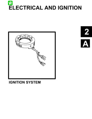
  • 1. ELECTRICAL AND IGNITION 2 A IGNITION SYSTEM 90-831996R1 JUNE 1996 ELECTRICAL AND IGNITION 2A-–1
  • 2. Table Of Contents Page Page Special Tools Required . . . . . . . . . . . . . . . . . . . 2A-1 Removing Flywheel . . . . . . . . . . . . . . . . . . . . . . 2A-7 General . . . . . . . . . . . . . . . . . . . . . . . . . . . . . . . . . 2A-1 Installing Flywheel . . . . . . . . . . . . . . . . . . . . . . . . 2A-8 Principles of Operation . . . . . . . . . . . . . . . . . . . . 2A-1 Removing Stator . . . . . . . . . . . . . . . . . . . . . . . . . 2A-8 Test Procedures . . . . . . . . . . . . . . . . . . . . . . . . . 2A-1 Installing Stator . . . . . . . . . . . . . . . . . . . . . . . . . . 2A-8 Testing For Spark . . . . . . . . . . . . . . . . . . . . . . . . 2A-2 Removing Trigger . . . . . . . . . . . . . . . . . . . . . . . . 2A-8 Testing Primary Input Voltage . . . . . . . . . . . . . . 2A-2 Installing Trigger . . . . . . . . . . . . . . . . . . . . . . . . . 2A-9 Test Switch Box “Stop” Circuit. . . . . . . . . . . . . . 2A-3 Removing Switch Box . . . . . . . . . . . . . . . . . . . . 2A-9 Testing Stator Output . . . . . . . . . . . . . . . . . . . . . 2A-3 Installing Switch Box . . . . . . . . . . . . . . . . . . . . . . 2A-9 Testing Stator Resistance . . . . . . . . . . . . . . . . . 2A-3 Removing Coils . . . . . . . . . . . . . . . . . . . . . . . . . 2A-10 Testing Switch Box Bias Circuit- Installing Coils . . . . . . . . . . . . . . . . . . . . . . . . . . 2A-10 90 HP Only . . . . . . . . . . . . . . . . . . . . . . . 2A-4 Ignition Diagram 90 HP Sport Jet . . . . . . . . . . 2A-11 Testing Trigger Resistance . . . . . . . . . . . . . . . . 2A-4 Ignition Wiring Diagram Testing Ignition Coils . . . . . . . . . . . . . . . . . . . . . . 2A-5 120 Sport Jet . . . . . . . . . . . . . . . . . . . . . . . . 2A-12 Erratic/Misfire or No Fire Condition . . . . . . . . . 2A-6 2A-0 ELECTRICAL AND IGNITION 90-831996R1 JUNE 1996
  • 3. The stator assembly is mounted stationary below the Special Tools Required flywheel and has two capacitor charging coils. The fly- Multimeter/ DVA Tester 91-99750 wheel is fitted with permanent magnets inside the out- er rim. As the flywheel rotates the permanent mag- nets pass the capacitor charging coils. This causes the capacitor charging coils to produce AC voltage. The AC voltage then is conducted to the switch box where it is rectified and stored in a capacitor. The trigger assembly (also mounted under the fly- wheel) has 2 coils. The flywheel likewise has a sec- ond set of permanent magnets (located around the center hub). As the flywheel rotates the second set of magnets pass the trigger coils. This causes the trig- ger coils, in turn, to produce an AC voltage that is con- ducted to an electronic switch (SCR) in the switch Spark Tester 91-850439 box. The switch discharges the capacitor voltage into the primary side of the ignition coil. The ignition coil multiplies this voltage to a value high enough to jump the gap at the spark plug. The preceding sequence occurs once per engine rev- olution for each cylinder. Spark timing is changed (advanced/retarded) by ro- tating the trigger assembly which changes each trig- ger coil position in relation to the permanent magnets 55117 on the flywheel hub. General Test Procedures The ignition system used on the Sport Jet engines is self-energizing (creates it’s own power for ignition) WARNING and has proven reliability. Should testing be required When testing or servicing the ignition system it is important to check all components in the order high voltage is present. Be extremely cautious! outlined. DO NOT TOUCH OR DISCONNECT any ignition parts while engine is running, while key switch is IMPORTANT: Read the entire procedure before at- on, or while battery cables are connected. tempting to test components. The procedures in this section are designed to test the complete ignition system. In an actual situation CAUTION test only the components that control the misfiring cyl- Failure to comply with the following items may inder(s). result in damage to the ignition system. S DO NOT reverse battery cable connections. The WARNING battery negative cable is (–) ground. DO NOT When testing or servicing the ignition system “spark” battery terminals with battery cable con- high voltage is present; be extremely cautious! nections to check polarity. DO NOT TOUCH OR DISCONNECT any ignition S DO NOT disconnect battery cables while engine components while engine is cranking or running. is running. Principles of Operation S DO NOT crank engine when switch box is not grounded to engine. The ignition system is alternator driven with distribu- The switch box cannot be thoroughly checked with torless capacitor discharge. Major components of the conventional test equipment. If a Multimeter/DVA ignition system are the flywheel, stator, trigger, switch Tester is not used systematically check the switch box, ignition coils and spark plugs. box. 90-831996R1 JUNE 1996 ELECTRICAL AND IGNITION 2A-1
  • 4. All other components can be tested with an ohmme- Check that safety stop switch lanyard is in place. If ter. Before troubleshooting the ignition system: safety lanyard is NOT in place, spark plugs will not S Make sure the electrical harness and ignition fire. switch are not the source of the problem. 9. Isolate the stop circuit by disconnecting black/ S Check that plug-in connectors are fully engaged yellow bullet connector from the switch box. and terminals are free of corrosion. IMPORTANT: Be sure this lead is not grounded. S Make sure that wire connections are tight and 10. Crank motor. free of corrosion. Results: Action Required: S Check that all electrical components and sepa- All cylinders spark nor- Repair stop circuit:igni- rate ground wires are grounded directly to en- mally tion key switch and/or gine. boat wiring. S Check for disconnected wires, short and open No spark Go to next step circuits. Testing For Spark Testing Primary Input Voltage 1. Adjust spark tester to a 7/16” gap setting. 1. Prepare multimeter. S Plug meter leads in as shown. S Set dial to 400 DVA scale. 7/16 in. 2. Connect red meter lead to #1 coil (+) terminal. 2. Secure spark tester to a good engine ground. 3. Connect black meter lead to #1 coil (–) terminal. 3. Remove leads from spark plugs. 4. Connect spark plug leads to corresponding spark tester leads. 5. Remove spark plugs. Engine must be able to crank at 600 RPM minimum for the following tests. 6. Crank motor. Results: Action Required: Spark jumps 7/16 in. Ignition system is opera- 4. Crank motor and observe meter. gap (all cylinders) tional, check timing se- 5. Repeat test for each coil. quence if required IMPORTANT: DO NOT use a common ground. No spark Go to next step Connect black meter lead to the ground of coil 7. Check all grounds and wire connections. being tested. Repair as needed. Results: Action Required: 8. Recheck spark output. 150 - 250 volts Go to Testing Coils Less than 150 volts Go to Next Step 2A-2 ELECTRICAL AND IGNITION 90-831996R1 JUNE 1996
  • 5. Test Switch Box “Stop” 2. Crank motor while reading meter. 90 and 120 HP Circuit. Results: Action Required: 1. Prepare multimeter as shown. 200-300 volts Low speed stator is O.K.: Go to Testing Trig- RED ger METER LEAD Less than 200 volts or Go to next step. If stator intermittent tests O.K., replace switch box. 3. Stator high-speed input to switch box. S Connect red meter lead to red stator lead. S Connect black meter lead to a good ground. S Set meter to 400 DVA scale. 4. Crank motor while reading meter. S Disconnect black/yellow lead form switch box. 90 and 120 HP S Attach red meter lead to black/yellow lead from switch box. Results: Action Required: 20-90 volts High speed stator is S Attach black meter lead to ground. O.K.: Go to Testing Trig- 2. Crank motor and observe meter. ger. Less than 20 volts or in- Go to next step termittent Testing Stator Resistance 1. Prepare multimeter (Special Tool No. 91-99750). Results: Action Required: 200-360 volts Go to Testing Trigger. If checks O.K., replace switch box. Less than 200 volts Go to next step S Plug in meter leads as shown. Testing Stator Output S Set dial to X1K ohm position. IMPORTANT: All leads must remain connected to S Calibrate meter. the switch box for the following DVA tests. 2. Low speed resistance test. 1. Stator low speed input to switch box. NOTE: This test is not polarity sensitive. S Connect red meter lead to blue lead from stator. S Connect black meter lead to a good engine ground. S Set meter to 400 DVA scale. 90-831996R1 JUNE 1996 ELECTRICAL AND IGNITION 2A-3
  • 6. 90 HP: Testing Switch Box Bias Circuit- S Disconnect blue and red stator leads from switch 90 HP Only box. 1. Prepare multimeter as shown. S Connect meter leads between blue and red sta- tor leads. Results: Action Required: 3600 - 4200* ohms Go to next test Above or below Replace stator 3600 - 4200 ohms *Copper is an excellent conductor, but resistance may notably vary between low and high temperature. Therefore, reasonable differences can be accepted between resistance readings and specifications. 120 HP: BLACK 20 DCV RED S Disconnect blue and blue/white stator leads from METER SCALE METER switch box. LEAD LEAD S Connect meter leads between blue and blue/ NOTE: White/black lead must remain connected to white stator leads. switch box for this test. 3. Observe meter reading. S Attach Black meter lead to white/black lead from Results: Action Required: switch box. 6800 - 7600* ohms Go to next test S Attach Red meter lead to ground. Above or below Replace stator 2. Crank motor and observe meter reading. 6800 - 7600 ohms Results: Action Required: *Copper is an excellent conductor, but resistance 2 - 10 volts Go to testing Trigger. If may notably vary between low and high temperature. trigger tests O.K. re- Therefore, reasonable differences can be accepted place switch box. between resistance readings and specifications. Below 2 volts Replace switch box. 4. High speed resistance test. S Set meter scale to X1 ohm. Testing Trigger Resistance 90 HP: 1. Prepare multimeter. S Disconnect red stator lead from switch box. S Plug meter leads in as shown. S Connect meter leads between red and engine S Set dial to x100 ohm. ground (if stator has been removed from engine connect meter leads between red stator lead and S Calibrate meter. stator ground). 120 HP: S Disconnect red and red/white stator leads from switch box. S Connect meter between red stator lead and red/ white stator leads. 5. Observe meter reading. Results: Action Required: 90 - 140 ohms Stator O.K., continue electrical testing Above or below 90 - 140 Replace stator ohms 2A-4 ELECTRICAL AND IGNITION 90-831996R1 JUNE 1996
  • 7. 2. Disconnect trigger leads. Test resistance be- tween trigger leads as shown in the following chart. This test is not polarity sensitive. 90 HP Meter Leads Meter Reading Between Brown and White/Black Between White and 1100 - 1400 Oh Ohms White/Black Between Violet and White/Black S Red meter lead to #1 coil (+) terminal. 120 HP S Black meter lead to #1 coil (–) terminal. Meter Leads Meter Reading This test is not polarity sensitive. Between Violet and White 3. Observe meter. Between Brown and 700 - 1000 Oh Ohms Results: Action Required: White/Black .02 - .04* ohms Go to next step *Copper is an excellent conductor, but resistance Above or below .02 - .04 Replace coil may notably vary between low and high temperature. ohms Therefore, reasonable differences can be accepted *The primary DC resistance of these coils generally is less between resistance readings and specifications. than one ohm. If a reading resembling a short is obtained, this would be acceptable. 3. Replace trigger as necessary. 4. Repeat test for each coil. 5. Check secondary resistance. Testing Ignition Coils S Remove spark plug wire from coil tower. 1. Check primary resistance. S Set dial to X100 scale. S Calibrate meter. S Prepare multimeter as shown. S Set dial to X1 scale. S Calibrate meter S Disconnect coil input leads. 2. Connect meter leads. 90-831996R1 JUNE 1996 ELECTRICAL AND IGNITION 2A-5
  • 8. S Connect meter leads between coil tower and coil positive (+) terminal. Erratic/Misfire or No Fire Condition Occasionally a problem may occur that will not show when testing at cranking speed. Some tests can be performed with the engine running at the particular RPM when the problem occurs. “Running” tests use the same procedures as “crank- ing” tests. Refer to the chart following for running test readings. S Observe meter reading. Results: Action Required: 800 - 1100* Go to next section Above or below 800 - Replace coil 1100 ohms *Copper is an excellent conductor, but resistance may notably vary between low and high temperature. Therefore, reasonable differences can be accepted between resistance readings and specifications. Test Selector DVA Leads Voltage Reading Voltage Reading Position Red Black @ 300-1000 RPM(1) @ 1000-4000 RPM Coil Coil (+) Coil (–) Primary 400VDC* Terminal Terminal 150-250 180-280 Sw. Box - Black/Yellow Stop circuit 400VDC* Sw. Box Connector Ground 200-360 200-360 Stator - Blue Sw. Low Speed 400VDC* Box Connector Ground 200-300 200-330 Stator - Red Sw. High Speed 400VDC* Box Connector Ground 20-90 130-300 *If using a meter with a built-in DVA, place selector in the DVA/400 VDC position. (1)Readings at cranking speed and/or idle speed. 2A-6 ELECTRICAL AND IGNITION 90-831996R1 JUNE 1996
  • 9. Removing Flywheel CAUTION WARNING Do not strike the screw too hard. This may damage the crankshaft and bearings. Always disconnect battery and remove spark plug leads from spark plugs before working on 4. Strike top of pressure screw (a) with hammer. motor. 1. Remove flywheel nut. a 5. Remove flywheel from crankshaft. Use a suitable flywheel holder to keep flywheel from turning. 2. Install puller (Special Tool No. FT-8948-1). 6. Remove puller form flywheel. 7. Remove flywheel key. Perform the following step while holding the puller bar. This will prevent the puller plate from turning. 3. Turn pressure screw until it is tight against the a crankshaft. a a - Flywheel Key 8. Inspect flywheel. S Carefully inspect flywheel for cracks or damage. WARNING A cracked or chipped flywheel must be replaced. a - Pressure Screw At high RPM a damaged flywheel may fly apart and throw metal over a large area. S Inspect crankshaft and flywheel tapers for worn or damaged key ways. 90-831996R1 JUNE 1996 ELECTRICAL AND IGNITION 2A-7
  • 10. S Check for loose magnet or damaged timing mag- 4. Remove screws and lift stator off bearing cage. net laminations. Arc burns on timing magnet laminations are normal. S Replace flywheel if necessary. a Installing Flywheel 1. Clean tapered surfaces of flywheel and crank- shaft with solvent. a S Blow dry tapered surfaces with compressed air. If the flywheel key appears damaged in any way re- place it. 2. Install flywheel key in crankshaft slot with outer a - Stator Screws edge of key parallel to center line of crankshaft. Installing Stator 1. Set stator on bearing cage. Secure with screws. IMPORTANT: Be sure the stator is positioned so the wire harness is on the port side of the motor. a 2. Connect yellow stator leads to yellow rectifier/re- gulator leads. 3. Connect all stator leads to corresponding switch box leads. 4. Install flywheel. a - Flywheel Key 3. Install flywheel. Removing Trigger S Place flywheel down over crankshaft. 1. Remove flywheel. S Install flywheel nut. SEE “REMOVING FLYWHEEL” IN THIS SECTION. S Torque flywheel nut to 125 lb. ft. (169.5 N·m). 2. Remove stator. SEE “REMOVING STATOR” IN THIS SECTION. 3. Disconnect all trigger leads from switch box leads. 4. Disconnect spark control link from tower shaft. 5. Lift trigger off bearing cage. a Removing Stator b 1. Remove flywheel. SEE “REMOVING FLYWHEEL” IN THIS SECTION. 2. Remove yellow stator leads from rectifier/regula- tor leads. 3. Disconnect all stator leads from switch box leads. Removal of switch box mounting bracket may be nec- a - Trigger essary to gain access to stator leads. b - Spark Control Link 2A-8 ELECTRICAL AND IGNITION 90-831996R1 JUNE 1996
  • 11. Installing Trigger Removing Switch Box 1. Install spark control link on new trigger. WARNING Always disconnect battery and disconnect spark plug leads from spark plugs before working on motor. a a - Spark Control Link 2. Lubricate outer ring of trigger with grease. 1. Remove three screws and clamp. 3. Place trigger on bearing cage. 2. Remove switch box from bracket. 4. Secure spark control link to towershaft. 3. Remove lead wires from switch box. a a b a - 90 HP Switch Box b - 120 HP Switch Box Installing Switch Box a - Towershaft 1. Position switch box on bracket. 5. Route lead wires under ignition harness guard and down to switch box. 2. Install screws and clamp. 6. Connect corresponding trigger leads to switch The clamp is attached with the lower forward mount- box leads: ing screw. 7. Install stator. 3. Attach lead wires. SEE INSTALLING STATOR IN THIS SECTION. Switch box leads are identified by color. Stator Leads Red, Blue, Red/White, 8. Install flywheel. Blue/White SEE INSTALLING FLYWHEEL IN THIS SECTION. Coil Leads Green, Green/White, 9. Check engine timing. Green/Red, Green/Black SEE ENGINE TIMING IN THIS SECTION. Stop Lead Black/Yellow Trigger Leads Brown, Violet, White, White/ Black 90-831996R1 JUNE 1996 ELECTRICAL AND IGNITION 2A-9
  • 12. Removing Coils Installing Coils 1. Attach wires to coil: WARNING S #1 Green Always disconnect battery and disconnect spark plug leads from spark plugs before working on S #2 Green/White motor. S #3 Green/Red S #4 Green/Black (120 HP) Positive (+) terminal is down. 2. Position coil/cover assembly on bracket. NOTE: 90 HP shown a b 1. Remove screws holding coil cover. c a a - #1 Green Terminal b - #2 Green/White Terminal c - #3 Green/Red Terminal 3. Slide coil into cover. 4. Position coil/cover assembly on bracket. 5. Install cover screws, tighten all fasteners. a - Screw 2. Remove coil/cover assembly from bracket. 3. Remove coil input wire (+) and ground wire (–) from coil. 4. Slide coil out of cover. NOTE: Coils are serviced individually. 2A-10 ELECTRICAL AND IGNITION 90-831996R1 JUNE 1996
  • 13. Ignition Diagram 90 HP Sport Jet Temperature Auto Enrichner Switch Oil Switch Low 90-831996R1 JUNE 1996 ELECTRICAL AND IGNITION 2A-11
  • 14. Ignition Wiring Diagram 120 Sport Jet Temperature Auto Enrichner Switch Oil Switch Low 2A-12 ELECTRICAL AND IGNITION 90-831996R1 JUNE 1996