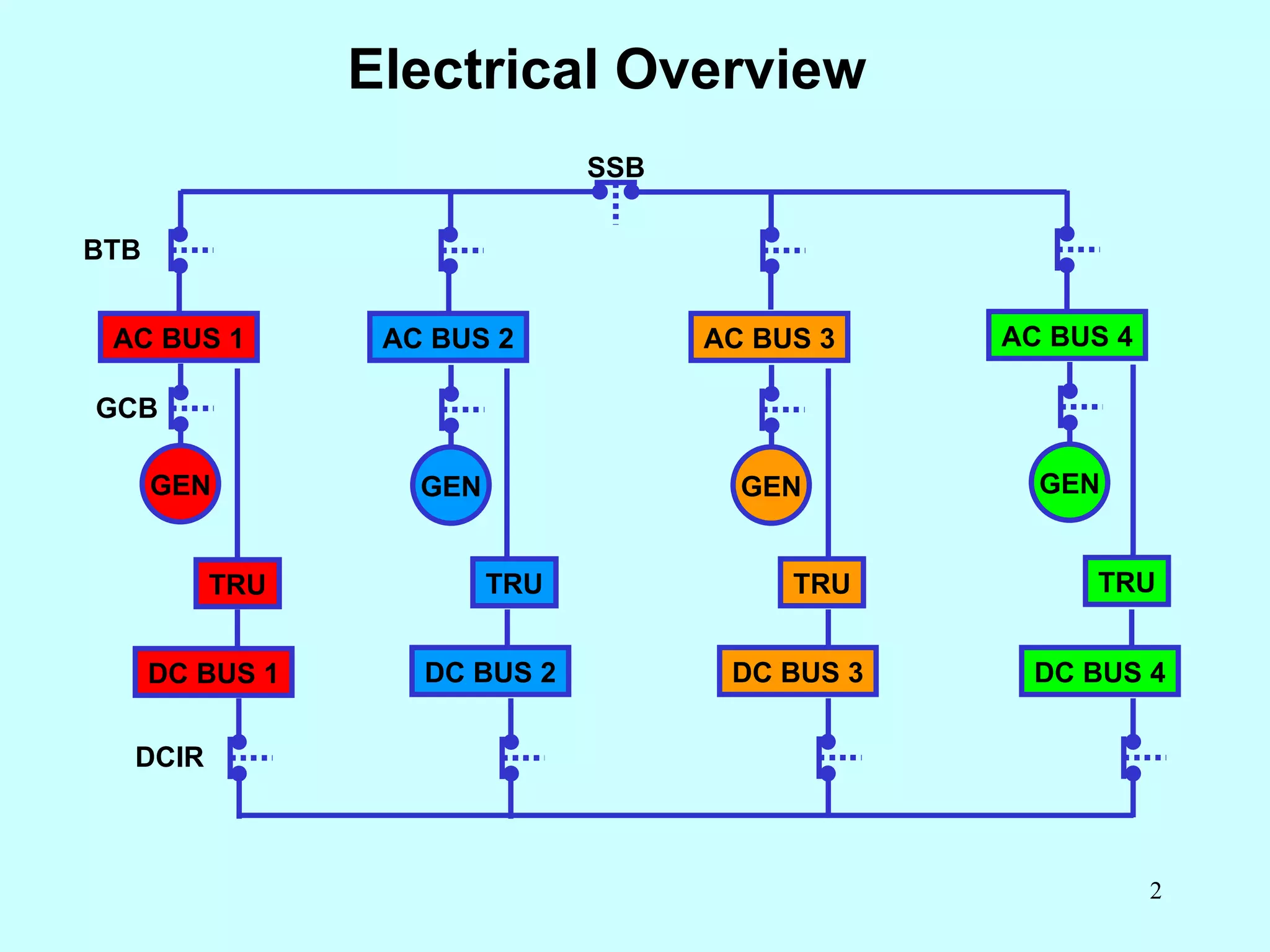
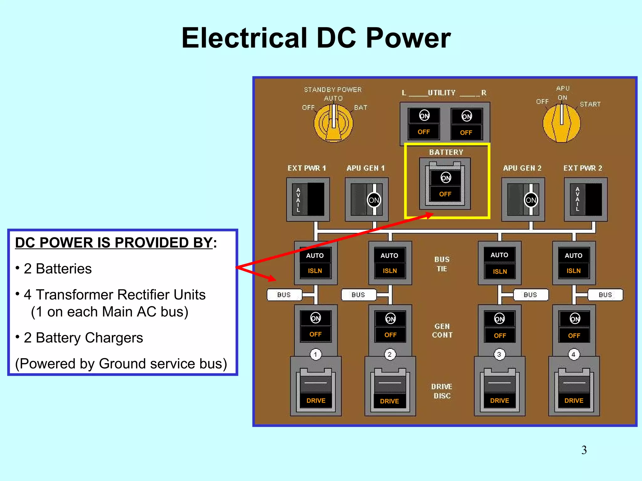
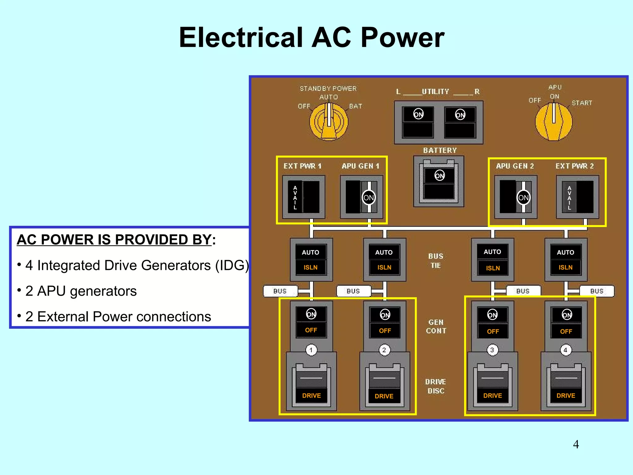
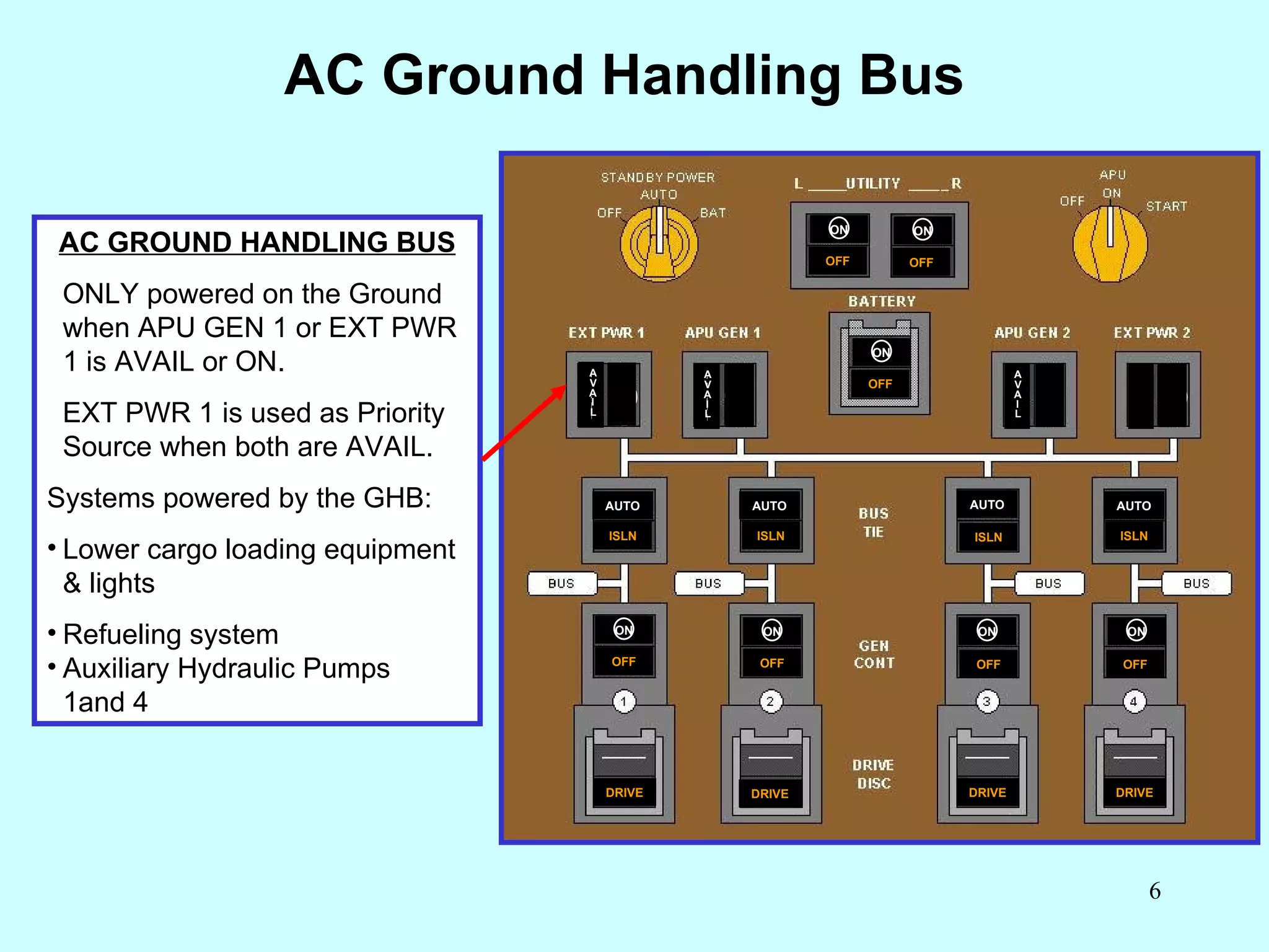
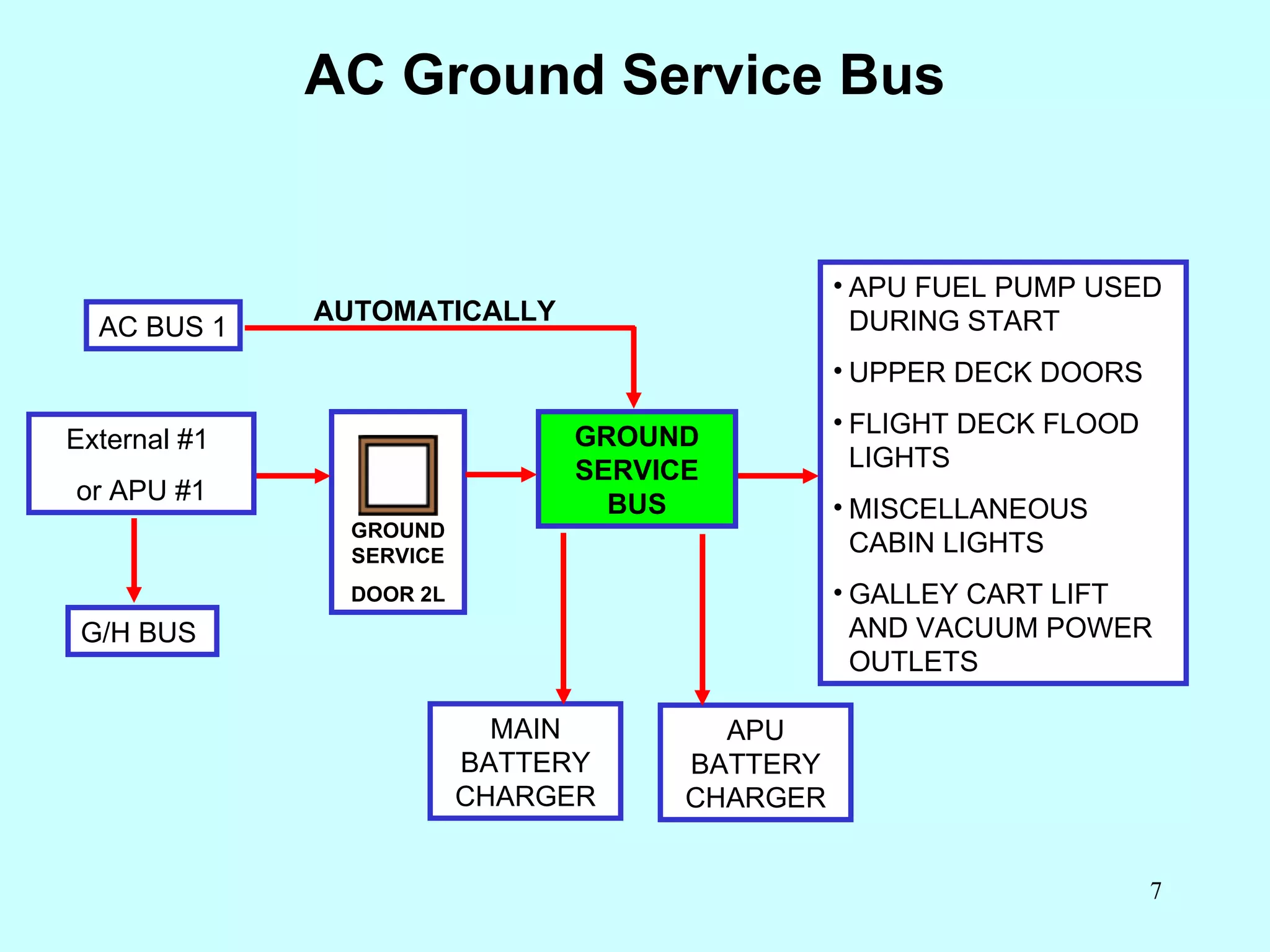
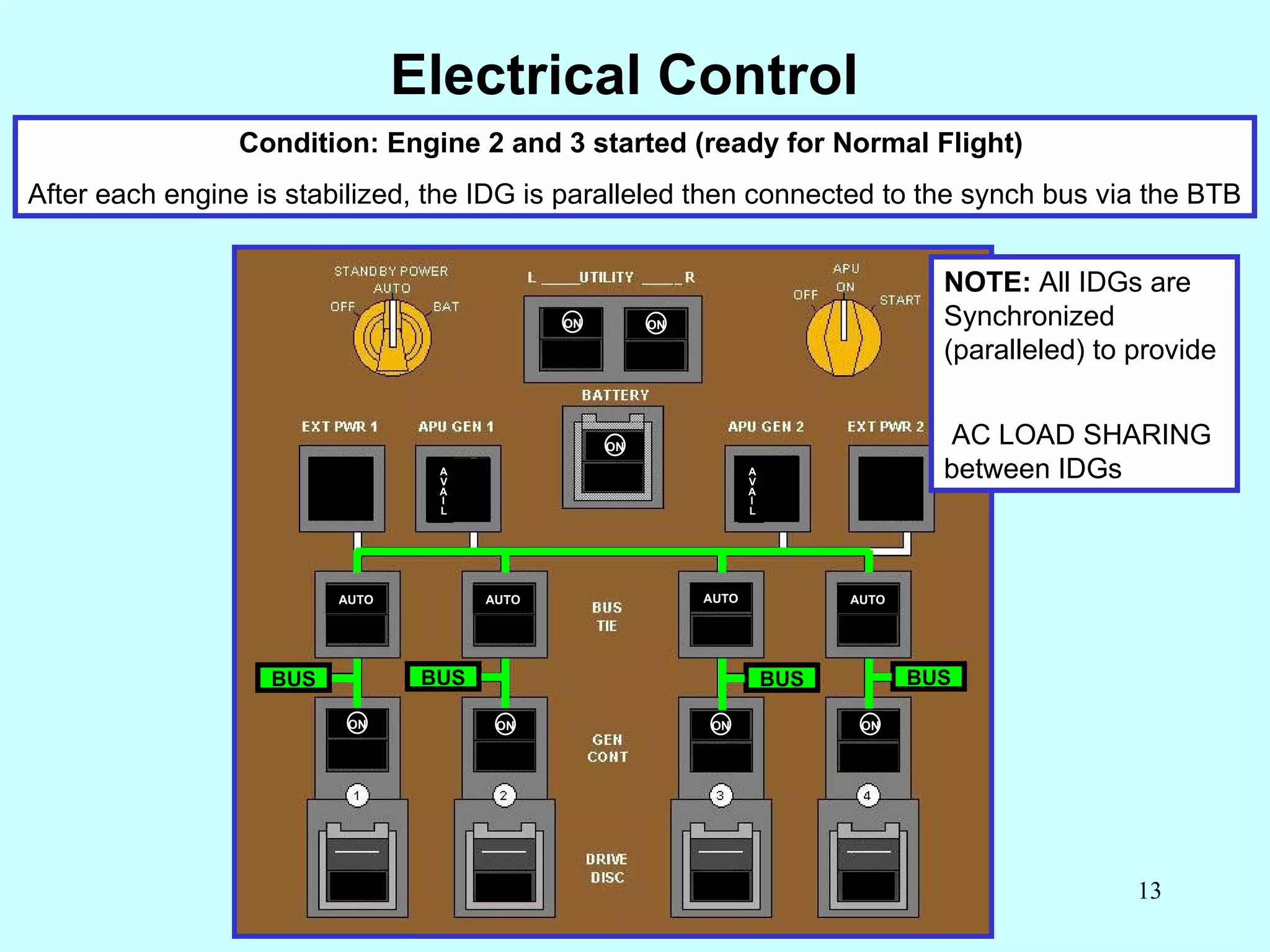
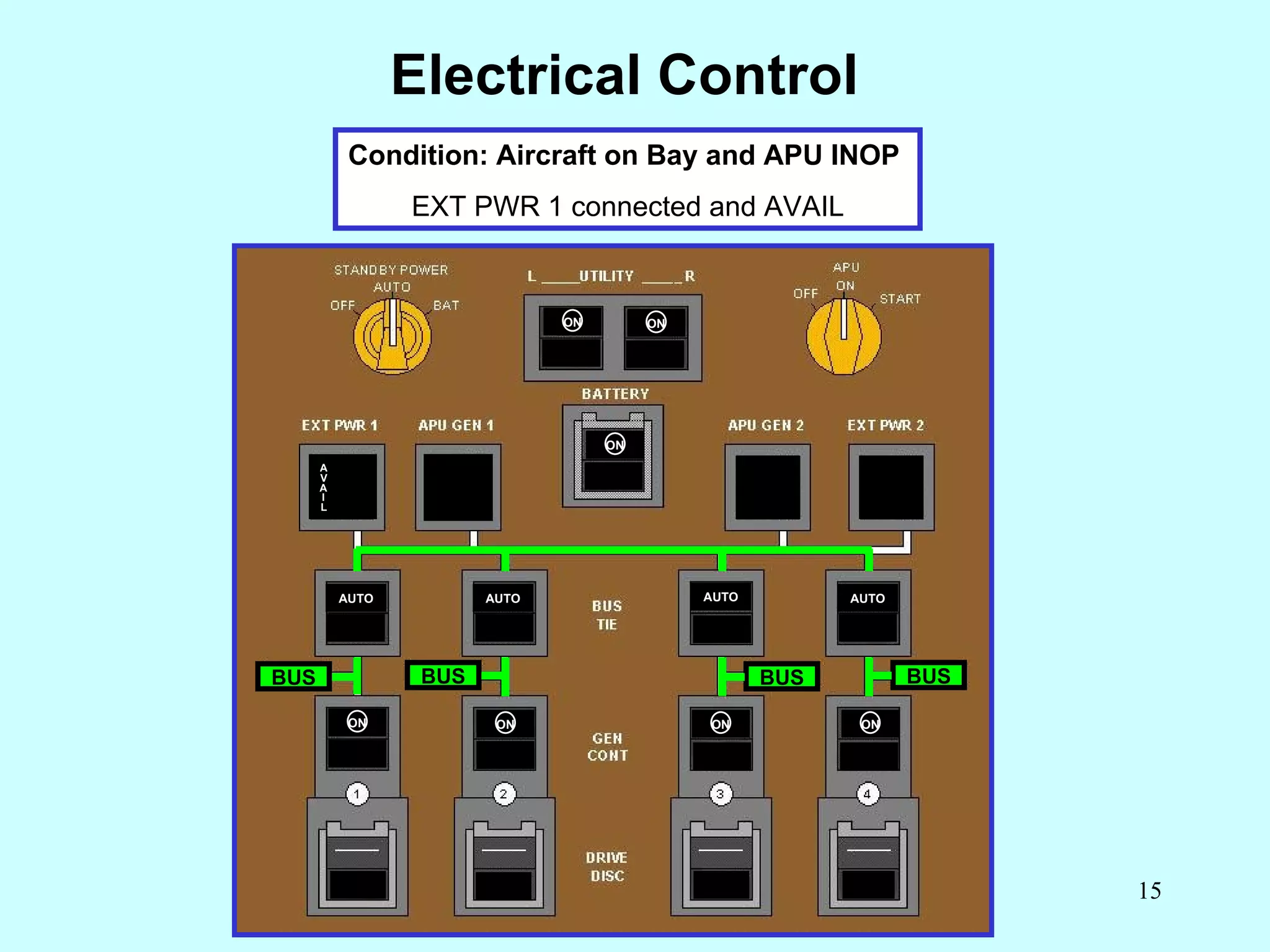
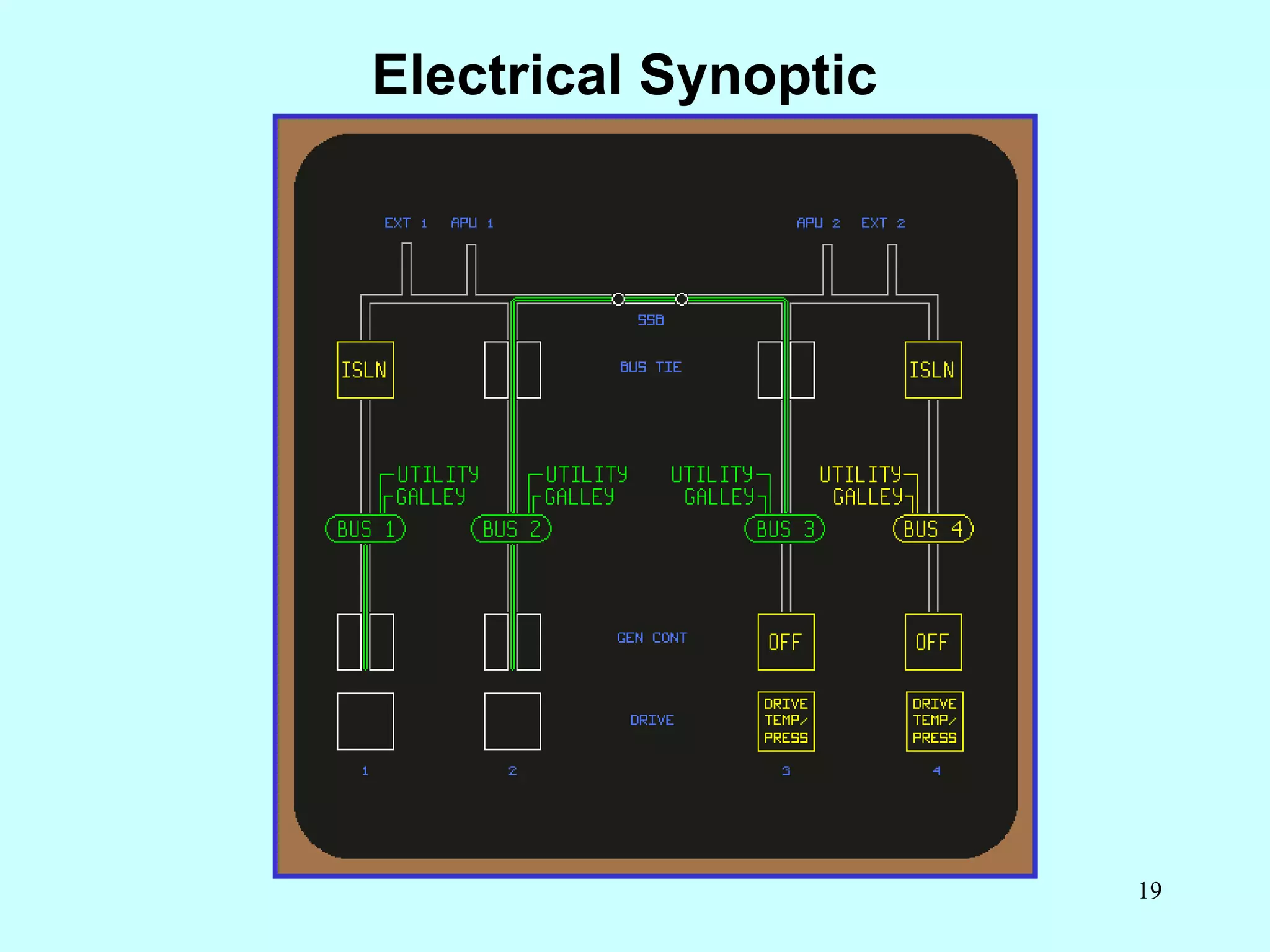
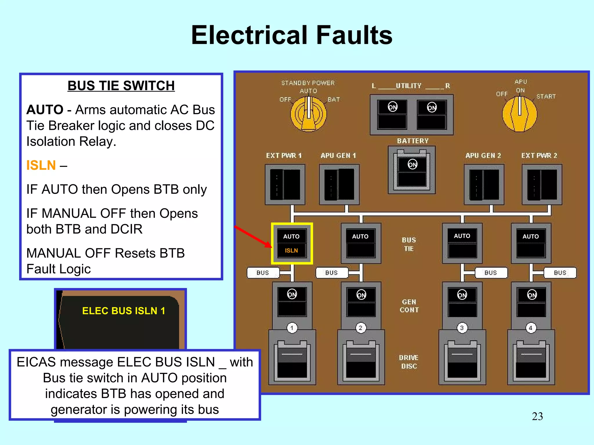
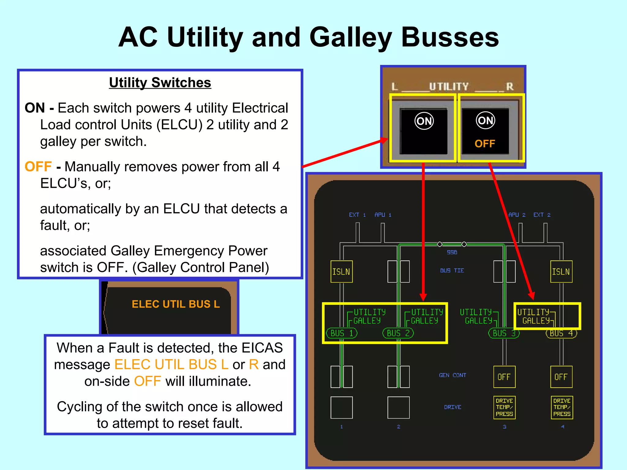
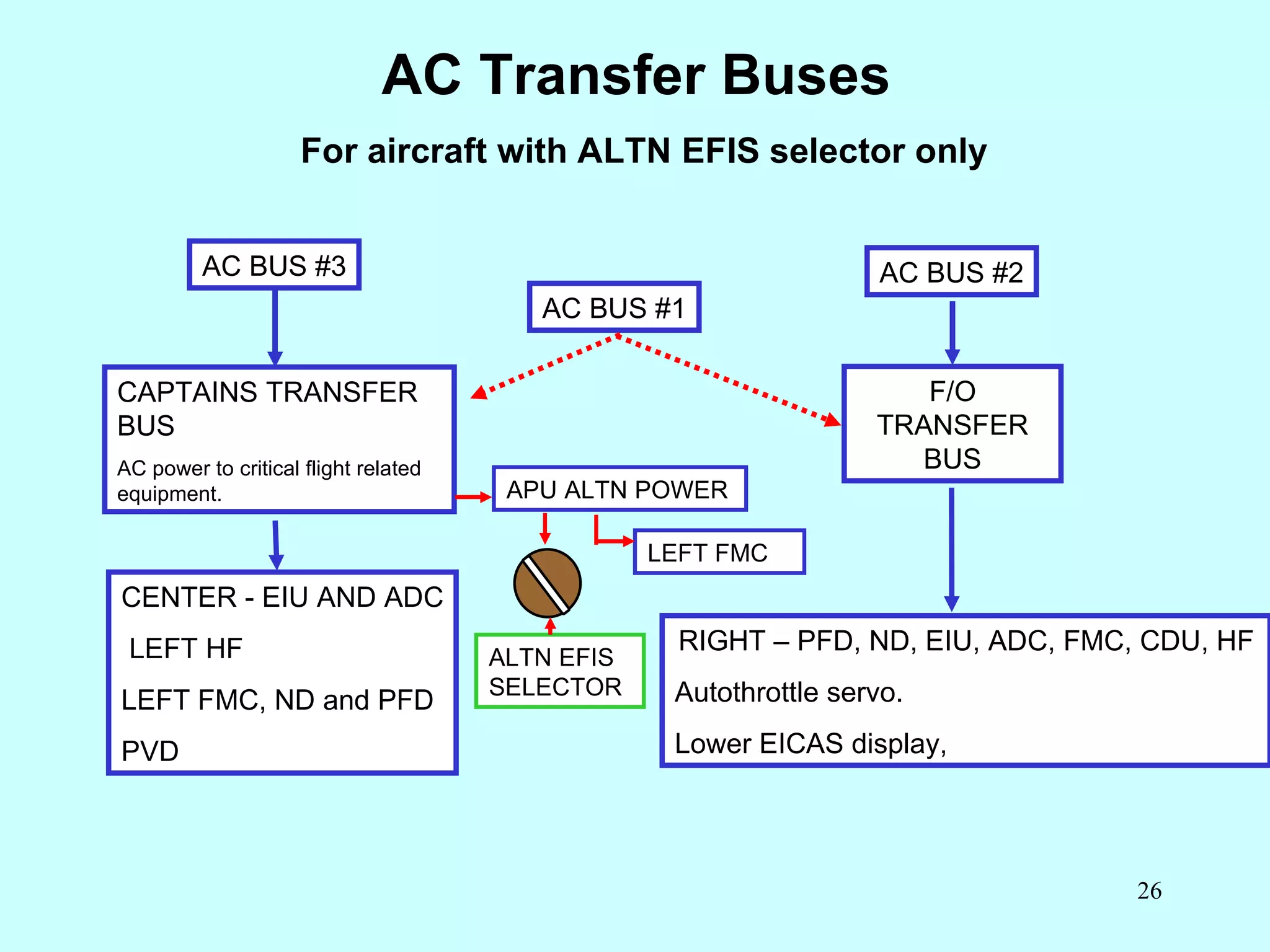
"Federated learning: out of reach no matter how close",Oleksandr Lapshyn
B747 Electrical Power
1. B 747-400 Flight Crew Conversion ELECTRICAL POWER www.theorycentre.com
2. Electrical Overview AC BUS 1 AC BUS 2 AC BUS 3 DC BUS 2 DC BUS 3 DC BUS 4 GEN GEN GEN AC BUS 4 TRU TRU TRU TRU DC BUS 1 SSB BTB GCB DCIR GEN
3.
4.
5. Electrical Synchronous Bus DRIVE DRIVE DRIVE DRIVE OFF OFF OFF OFF ON ON ON ON AUTO ISLN ISLN ISLN ISLN AUTO AUTO AUTO AVAIL AVAIL AVAIL AVAIL ON ON ON ON ON OFF ON OFF ON OFF SPLIT SYSTEM BREAKER (SSB) The split system breaker is used to electrically split the left and right synch buses. Note: Indications on ELEC synoptic or P461 panel SYNCH BUS During normal operation only the IDGs are Synchronized, and each IDG outputs to its AC bus. Each AC bus is connected via a Bus Tie Breaker to the Synchronous Bus, The Synch Bus evenly distributes the electrical AC power. It allows individual AC busses to remain powered if their generator is inoperative.
6.
7.
8. Electrical Control Condition: APU GEN 1 powering the Synchronous bus DRIVE DRIVE DRIVE OFF OFF OFF OFF AUTO AUTO AUTO AUTO AVAIL ON ON ON ON DRIVE ON ON ON ON ON ON ON BUS BUS BUS BUS A V A I L
9. Electrical Control Condition: APU GEN 1 and APU GEN 2 powering onside sync bus Split System Breaker is open DRIVE DRIVE DRIVE DRIVE OFF OFF OFF OFF ON ON ON ON AUTO AUTO AUTO AUTO AVAIL AVAIL ON ON ON ON ON ON ON BUS BUS BUS BUS
10. Electrical Control Condition: APU GEN 1 powering L/H side of the sync bus. Engine 4 started and IDG 4 powering R/H side of the sync bus via Bus Tie Breaker DRIVE DRIVE DRIVE DRIVE DRIVE DRIVE OFF OFF OFF ON ON ON ON AUTO AUTO AUTO AUTO AVAIL AVAIL ON ON ON ON ON ON ON BUS BUS BUS BUS A V A I L V I
11. Electrical Control Condition: Engine 1 started IDG 1 powering L/H side of the sync bus via BTB and IDG 4 powering R/H side of the sync bus OFF OFF OFF AUTO AUTO AUTO AUTO AVAIL AVAIL ON ON ON ON DRIVE DRIVE Momentary condition. ON ON ON ON ON ON ON BUS BUS BUS BUS A V A I L A V A I L
12. Electrical Control The IDGs are paralleled, then both sides are connected via the SSB . DRIVE DRIVE OFF OFF ON ON ON ON AUTO AUTO AUTO AUTO AVAIL AVAIL ON ON ON ON ON ON ON BUS BUS BUS BUS
13. Electrical Control Condition: Engine 2 and 3 started (ready for Normal Flight) After each engine is stabilized, the IDG is paralleled then connected to the synch bus via the BTB NOTE: All IDGs are Synchronized (paralleled) to provide AC LOAD SHARING between IDGs ON ON ON ON AUTO AUTO AUTO AUTO AVAIL AVAIL ON ON ON ON ON ON ON BUS BUS BUS BUS A V A I L A V A I L
14. Electrical Control Condition: Taxi In, Engines Running, and APU GEN 1 then APU GEN 2 ON GENs OFF, Split System Breaker opens and each APU GEN powers its side of the sync bus NOTE: Observe 6 second pause between selection of GEN1 and GEN2 to prevent APU gearbox overloading OFF OFF OFF OFF ON ON ON ON AUTO AUTO AUTO AUTO AVAIL AVAIL ON ON ON ON ON ON ON BUS BUS BUS BUS
15. Electrical Control Condition: Aircraft on Bay and APU INOP EXT PWR 1 connected and AVAIL OFF OFF OFF OFF AUTO AUTO AUTO AUTO ON ON ON ON ON ON ON ON ON ON ON BUS BUS BUS BUS A V A I L
16. Electrical Control Condition: EXT PWR 1 ON Will power the entire aircraft and shed ALL IDGs OFF OFF OFF OFF ON ON ON ON AUTO AUTO AUTO AUTO AVAIL ON ON ON ON ON ON ON BUS BUS BUS BUS DRIVE DRIVE DRIVE DRIVE
17. Electrical Control Condition: Aircraft on Bay and APU INOP EXT PWR 1 & 2 connected and AVAIL OFF OFF OFF OFF AUTO AUTO AUTO AUTO ON ON ON ON ON ON ON ON ON ON ON BUS BUS BUS BUS A V A I L A V A I L
18. Electrical Control Condition: EXT PWR 1 ON WITH 2 AVAILABLE SSB OPENS LEFT IDGs SHED LOADS OFF OFF ON ON ON ON AUTO AUTO AUTO AUTO AVAIL ON ON ON ON ON ON ON BUS BUS BUS BUS DRIVE DRIVE DRIVE DRIVE A V A I L
20. Electrical Faults DRIVE AUTO AUTO AUTO AUTO AVAIL AVAIL AVAIL AVAIL ON ON ON IDG DRIVE LIGHT Indicates; Low Oil Pressure or High Oil Temperature ELEC DRIVE 1 Some aircraft GCB Open Due to Frequency fault. GCB OFF LIGHT ILLUMINATED. ON ON ON ON ON ON ON
21. ELEC GEN OFF 1 DRIVE DISC SWITCH When pushed, disconnects the IDG from engine drive. NOTE: IDG cannot be reconnected in Flight. ELEC GEN OFF 1 will replace ELEC DRIVE 1 Electrical Faults DRIVE OFF ON ON ON ON AUTO AUTO AUTO AUTO AVAIL AVAIL AVAIL AVAIL ON ON ON
22. GEN CONT SWITCH ON - Arms GCB to close when generator power is acceptable. OFF - Opens GEN Field to stop GEN Electrical output and Opens GCB to Isolate GEN from its AC bus. Electrical Faults OFF ON ON ON ON AUTO AUTO AUTO AUTO AVAIL AVAIL AVAIL AVAIL ON ON ON ON ON ON ON
23. BUS TIE SWITCH AUTO - Arms automatic AC Bus Tie Breaker logic and closes DC Isolation Relay. ISLN – IF AUTO then Opens BTB only IF MANUAL OFF then Opens both BTB and DCIR MANUAL OFF Resets BTB Fault Logic EICAS message ELEC BUS ISLN _ with Bus tie switch in AUTO position indicates BTB has opened and generator is powering its bus Electrical Faults ON ON ON ON AUTO ISLN AUTO AUTO AUTO AVAIL AVAIL AVAIL AVAIL ON ON ON ON ON ON ON ELEC BUS ISLN 1
24. AC Utility and Galley Busses OFF ON OFF ON Utility Switches ON - Each switch powers 4 utility Electrical Load control Units (ELCU) 2 utility and 2 galley per switch. OFF - Manually removes power from all 4 ELCU’s, or; automatically by an ELCU that detects a fault, or; associated Galley Emergency Power switch is OFF. (Galley Control Panel) ELEC UTIL BUS L When a Fault is detected, the EICAS message ELEC UTIL BUS L or R and on-side OFF will illuminate. Cycling of the switch once is allowed to attempt to reset fault.
25.
26. AC Transfer Buses For aircraft with ALTN EFIS selector only CAPTAINS TRANSFER BUS AC power to critical flight related equipment. CENTER - EIU AND ADC LEFT HF LEFT FMC, ND and PFD PVD F/O TRANSFER BUS RIGHT – PFD, ND, EIU, ADC, FMC, CDU, HF Autothrottle servo. Lower EICAS display, AC BUS #3 AC BUS #2 AC BUS #1 APU ALTN POWER LEFT FMC ALTN EFIS SELECTOR
27. AC Transfer Buses For aircraft with no altn EFIS selector only CAPTAINS TRANSFER BUS CENTER - EIU AND ADC LEFT HF F/O TRANSFER BUS RIGHT – PFD, ND, EIU, ADC, FMC, CDU, HF AC BUS #3 AC BUS #2 AC BUS #1 APU STBY BUS Left FMC Left PFD Left ND
28. DRIVE DRIVE DRIVE DRIVE OFF OFF OFF OFF AUTO ISLN ISLN ISLN ISLN AUTO AUTO AUTO ON ON ON ON OFF OFF OFF STANDBY POWER SELECTOR OFF - Disconnects Main and APU standby busses from all power sources AUTO - Enables AUTO switching of Standby Bus power from available sources. BAT – Maintenance Use Only Disables main and APU Battery chargers. Supplies the Main Standby Bus from Main Battery only, and; APU Standby Bus from APU Battery only. AC Standby Power ON ON ON ON ON ON ON
29. AC Main Standby Power AC BUS 1 Aircraft with altn EFIS selector AC BUS 3 STANDBY BUS GROUND SERVICE BUS MAIN BAT CHARGER MAIN HOT BATTERY BUS MAIN BATTERY FAILURE OF BUS #1 FAILURE OF BUS #3 MAIN STBY INVERTER
30. AC Main Standby Power AC BUS 3 MAIN STANDBY BUS MAIN HOT BATTERY BUS MAIN BATTERY Aircraft with altn EFIS selector Left EIU, CDU, ILS, VOR, ADC and EFIS Control panel. Primary EICAS display. RMI Standby Instrument lights. Flap primary control. Flight control components. Standby Ignition for all engines. MAIN STBY INVERTER
31. CAPT APU STBY BUS F/O APU STBY BUS APU ALTN PWR AC BUS #1 AC BUS #2 F/O XFR BUS AC BUS #3 CAPT XFR BUS APU BATTERY APU HOT BAT BUS APU STAT INVERTER ALTN EFIS SELECTOR LEFT FMC LEFT - PFD AND ND RIGHT – PFD AND ND AC APU Standby Busses
32. AC Main Standby Power AC BUS 1 Aircraft with no altn EFIS selector AC BUS 3 MAIN STANDBY BUS GROUND SERVICE BUS MAIN BAT CHARGER MAIN HOT BATTERY BUS MAIN BATTERY FAILURE OF BUS #1 FAILURE OF BUS #3 MAIN STBY INVERTER
33. AC Main Standby Power AC BUS 3 MAIN STANDBY BUS MAIN HOT BATTERY BUS MAIN BATTERY Aircraft with no altn EFIS selector Left EIU, CDU, ILS, VOR, ADC and EFIS Control panel. Primary EICAS display. RMI Standby Instrument lights. Flap primary control. Flight control components. Standby ignition for all engines. MAIN STBY INVERTER
34. AC APU Standby Busses APU STBY BUS AC BUS #3 CAPT XFR BUS APU BATTERY APU HOT BAT BUS APU STAT INVERTER AC BUS #1 LEFT FMC LEFT - PFD AND ND Aircraft with no altn EFIS selector
35. DC Main Battery Bus MAIN HOT BATTERY BUS MAIN BATTERY BUS DC BUS #3 MAIN BATTERY CHARGER GRD SERVICE BUS AC BUS #1 MAIN BATTERY ENG, APU and cargo Fire Extinguishing. Fire switch unlock. APU fuel valve. Spar valves. Left VHF Left Radio tuning panel. Captains interphone. Standby attitude indicator. T/E Flap control Manual Cabin Pressurization IDG disconnects Main STBY Inverter APU ALT Control. Engine fuel valves. Fuel cross feed valves. Dome, storm and some indicator lights.
36. DC APU Battery Bus APU HOT BATTERY BUS APU BATTERY BUS DC BUS #3 APU BATTERY CHARGER GRD SERVICE BUS AC BUS #1 APU BATTERY ENG and APU Fire Detection APU Fire warning horn. APU DC fuel pump Engine start air control. F/o, Service and cargo interphones. P.A. system. IRS ON BAT LOCATED ON MAINTENANCE PANEL. IRS OPERATING ON BACKUP ELECTRICAL POWER. IRU’s x 3 Outflow Valves APU inlet door. APU primary control.
37. Autoland Isolation AC BUS 1 AC BUS 2 AC BUS 3 DC BUS 2 DC BUS 3 DC BUS 4 GEN AC BUS 4 TRU TRU TRU TRU DC BUS 1 SSB BTB GCB DCIR AUTOLAND ISOLATION At 1,500 Ft with APP mode selected the FCC’s signal Electrical System Logic GEN GEN GEN