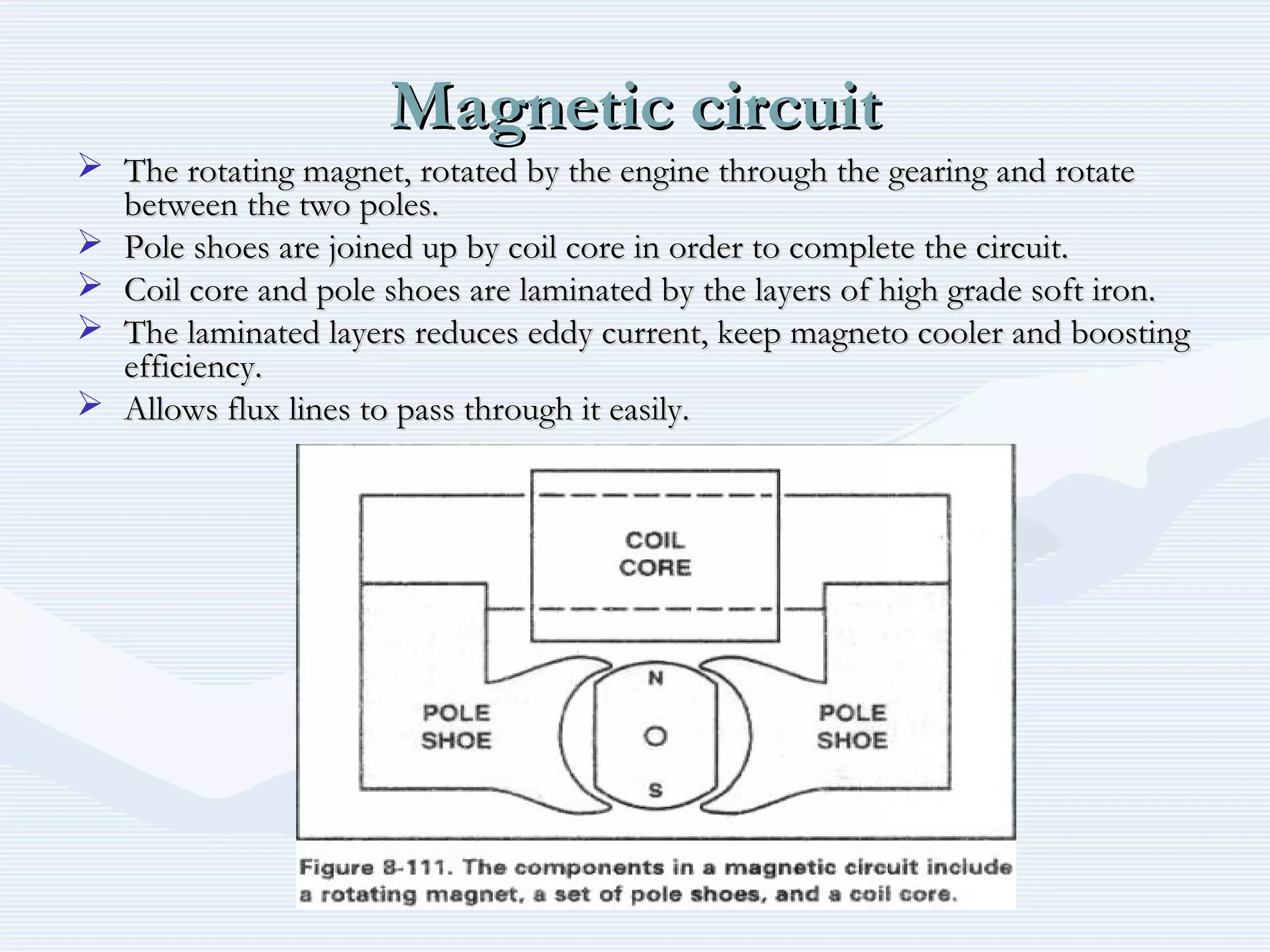
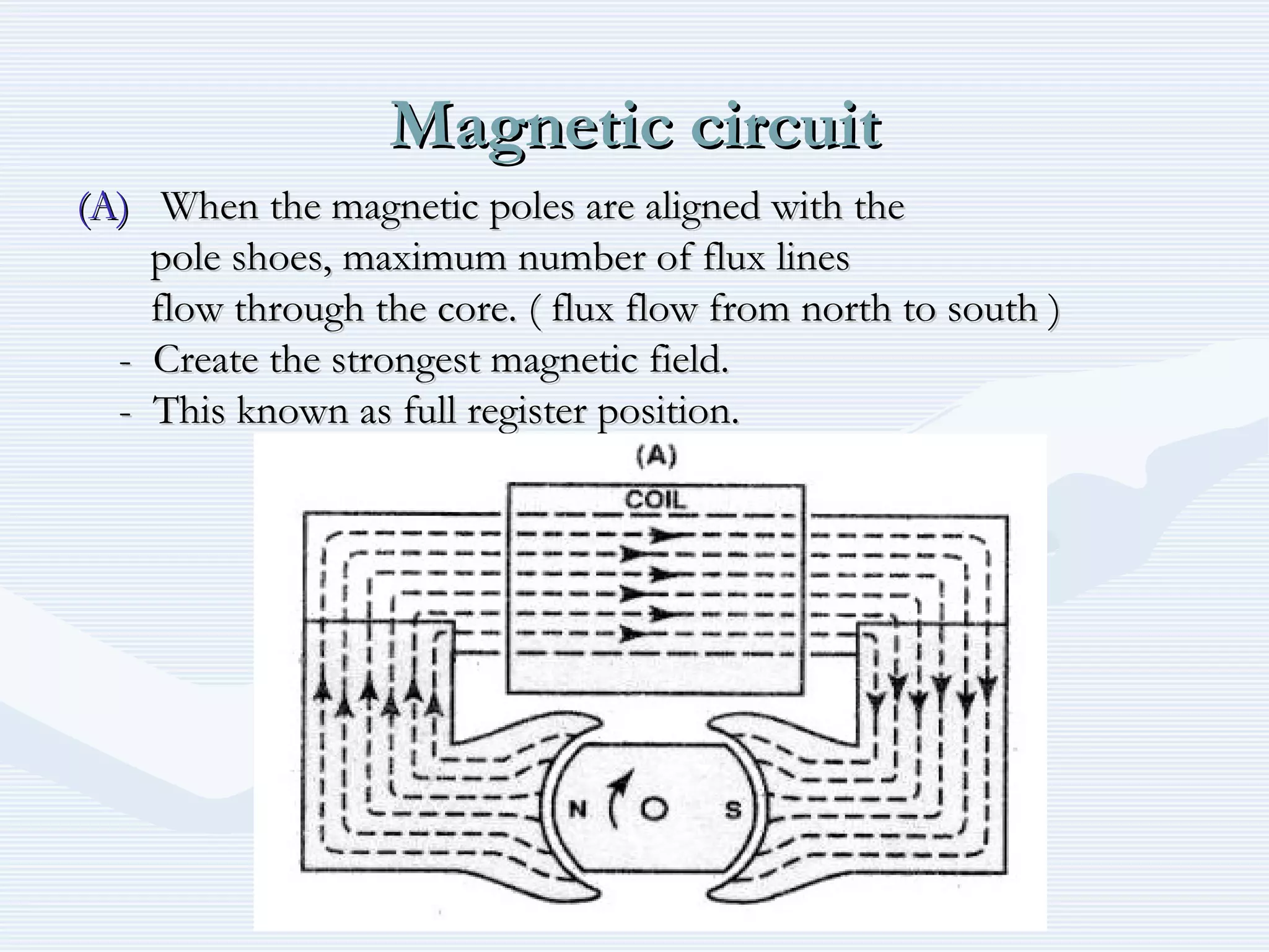
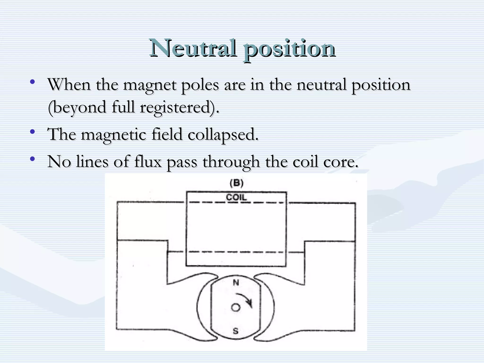
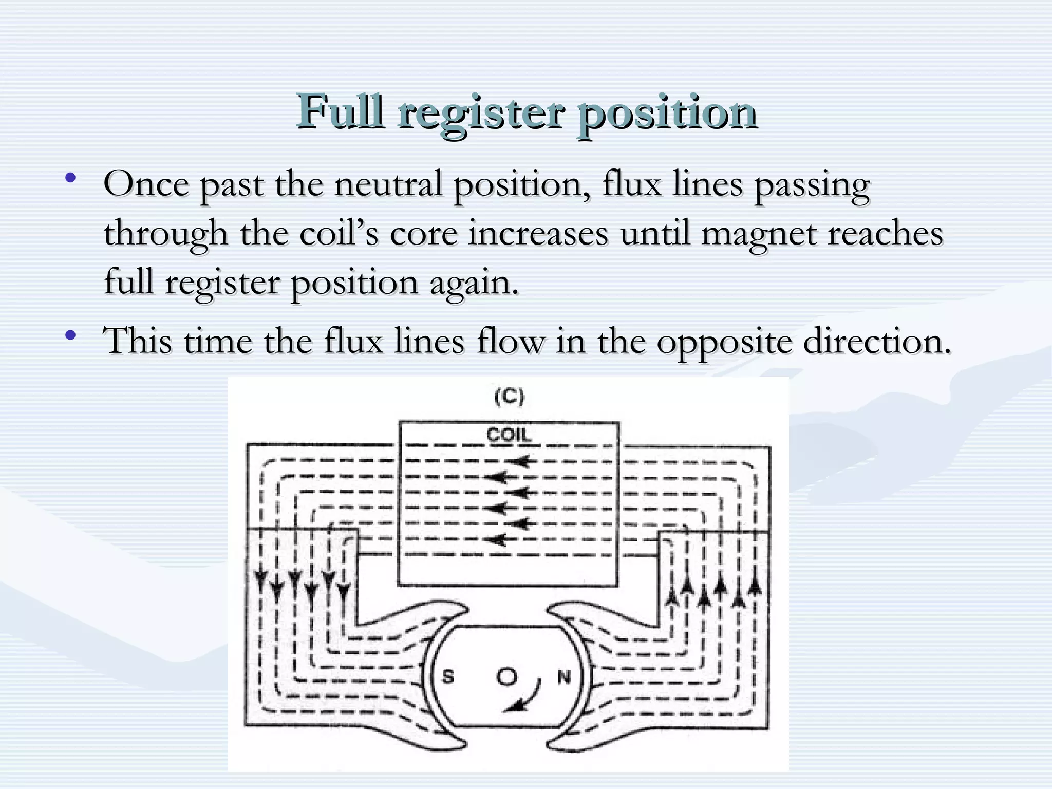
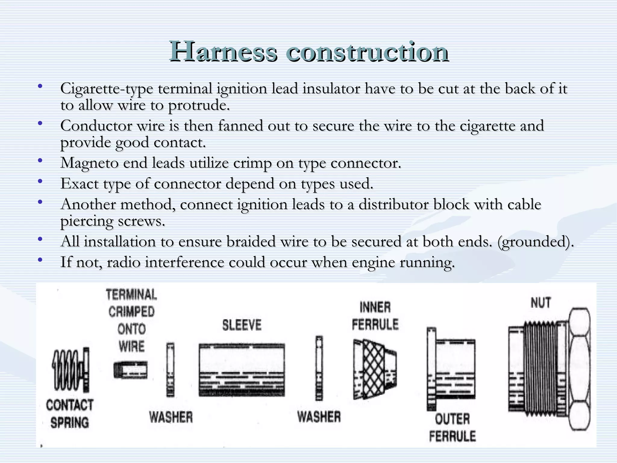
Downloaded 202 times
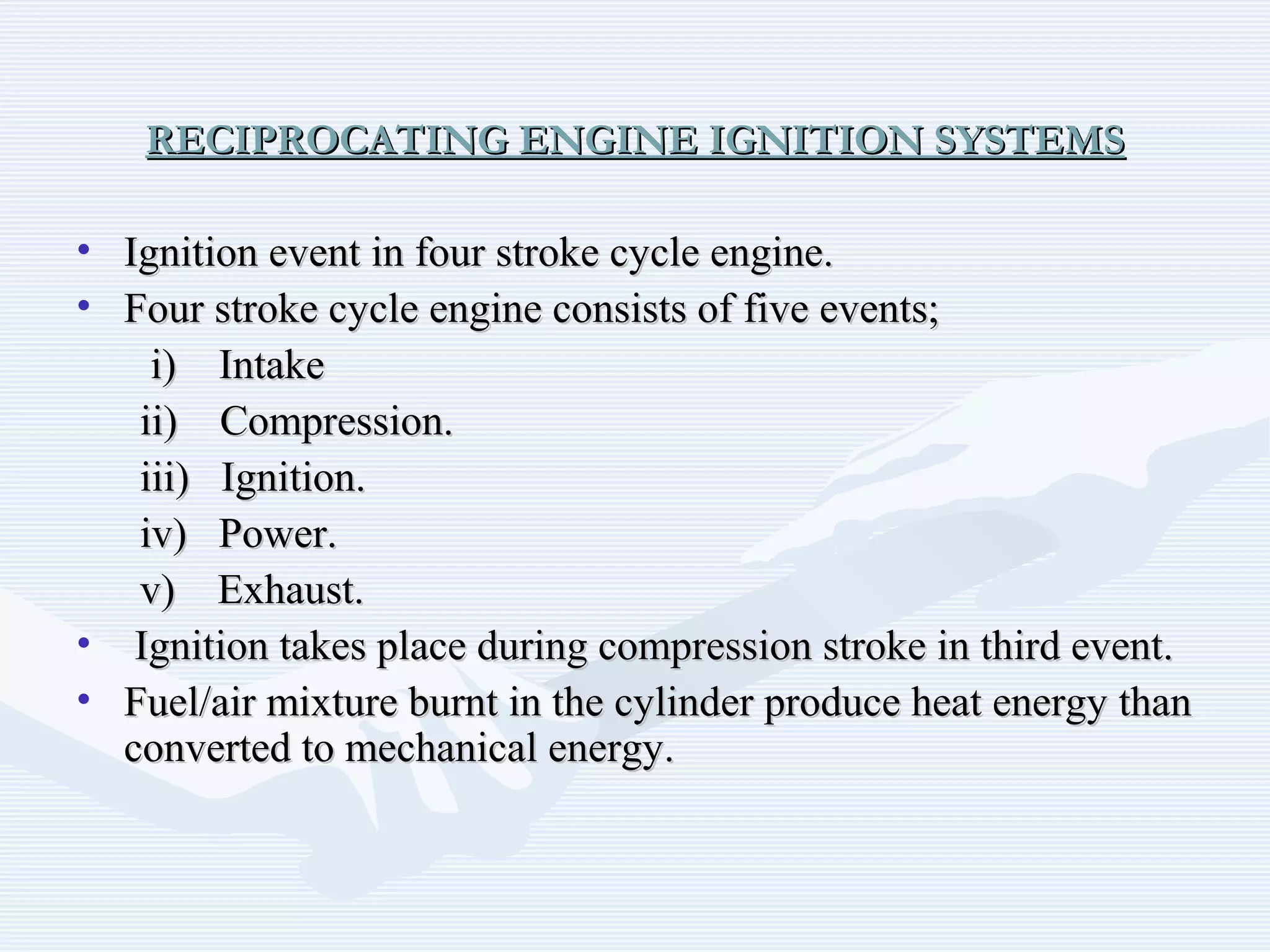
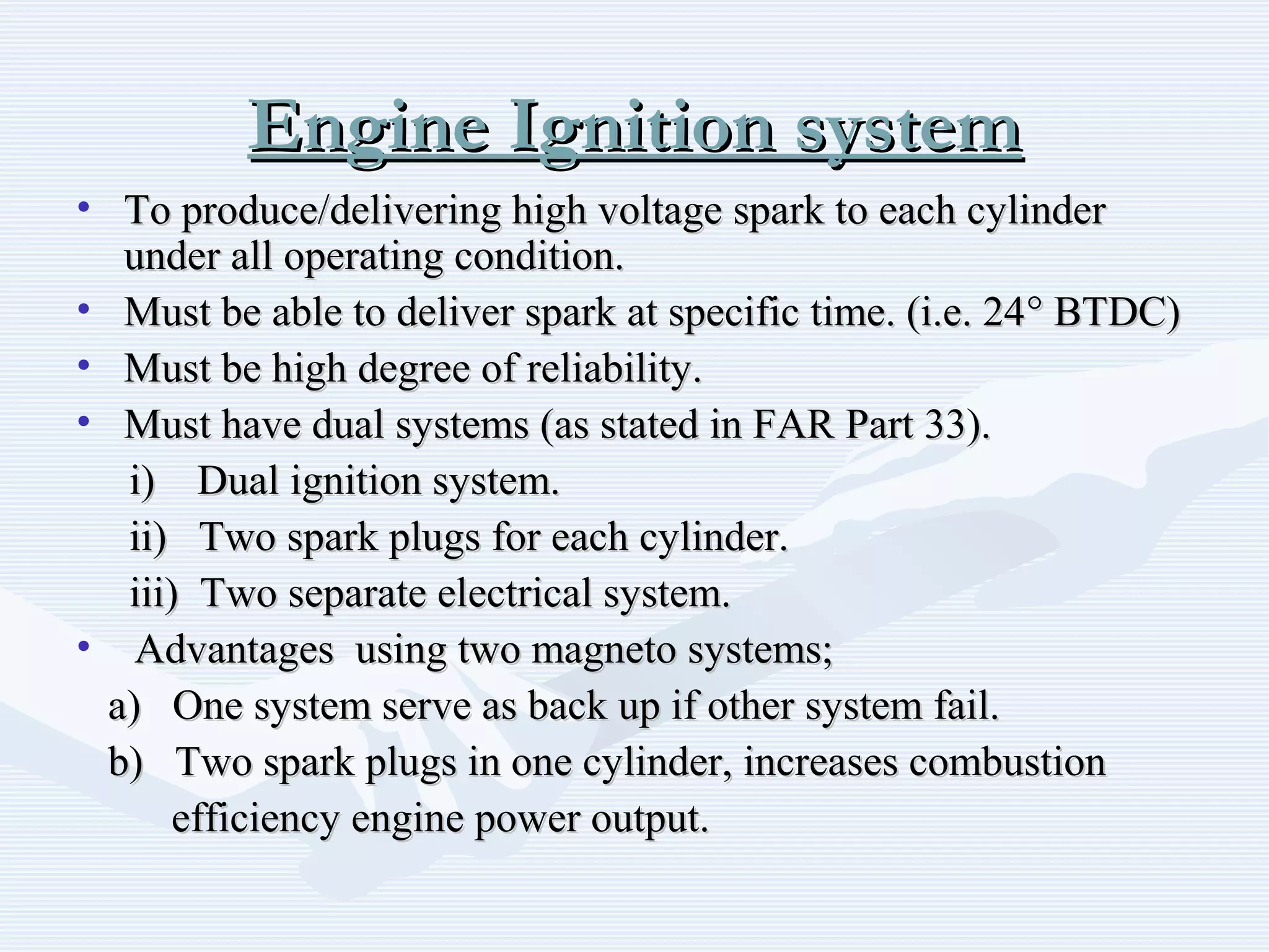
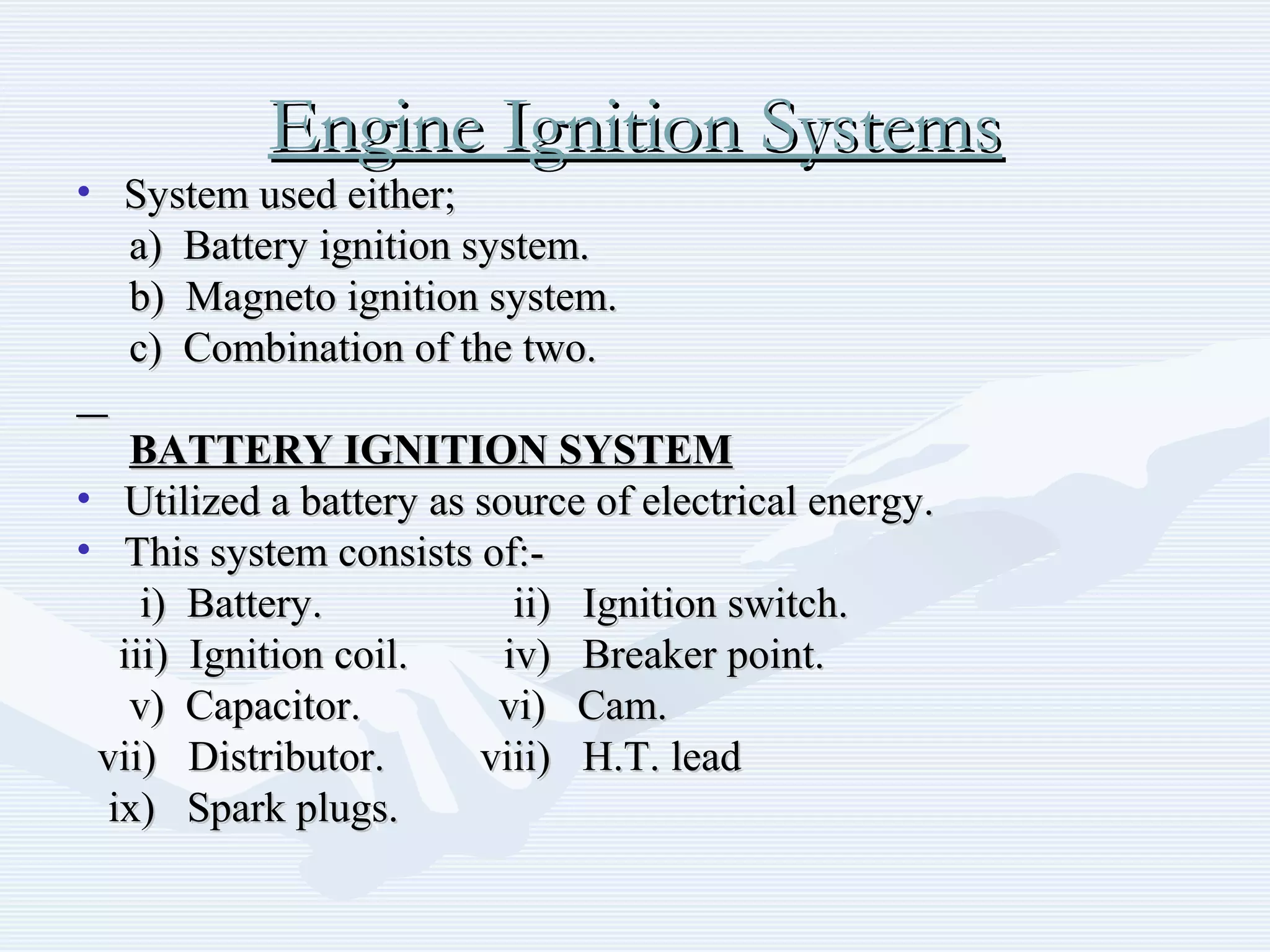
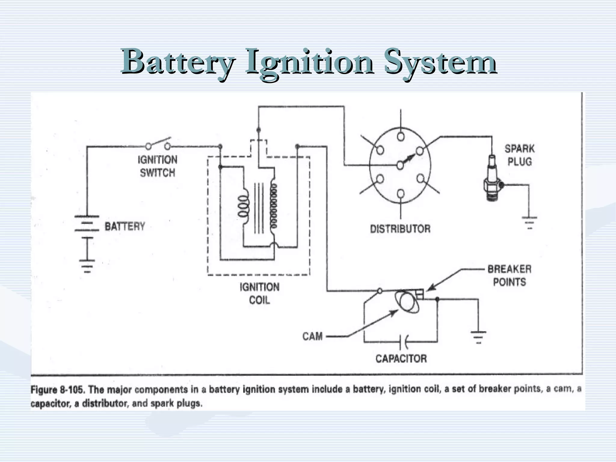
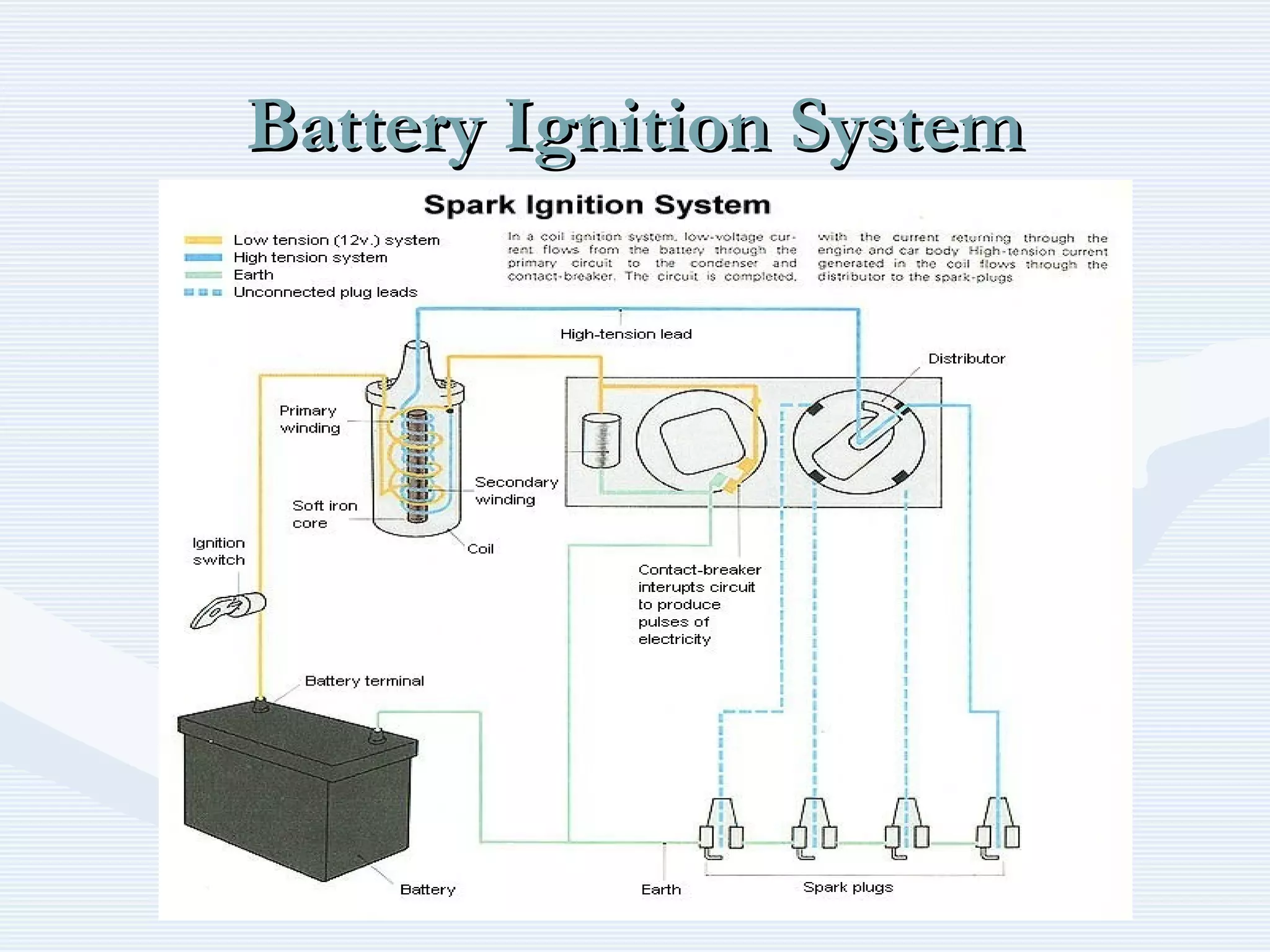
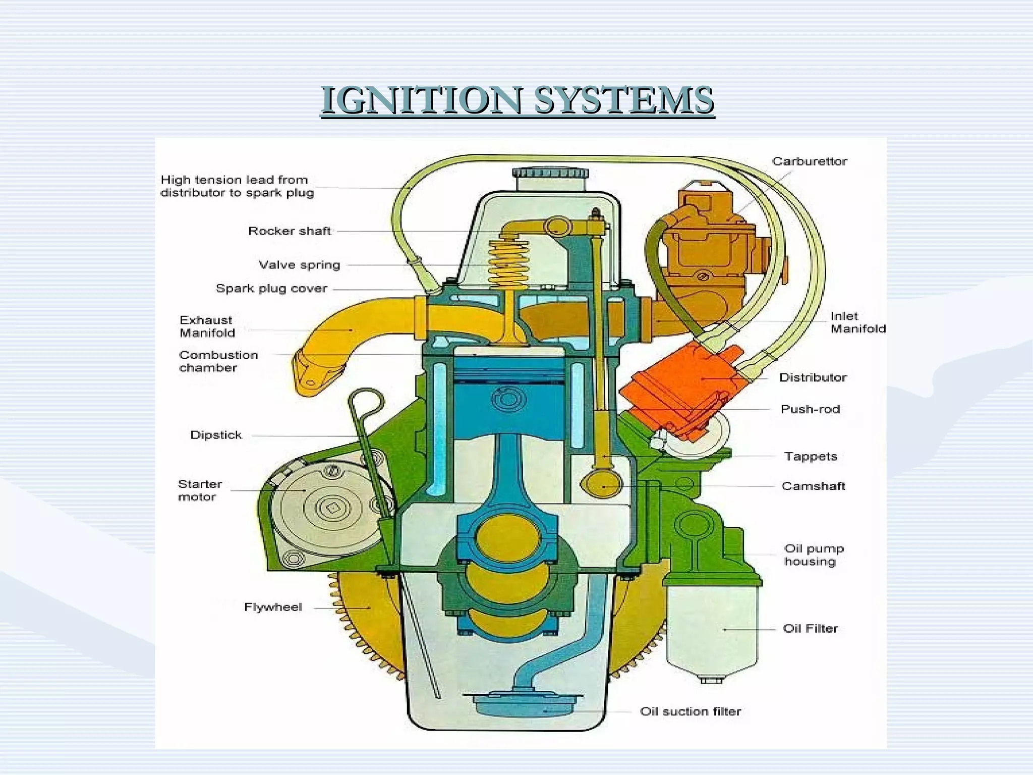
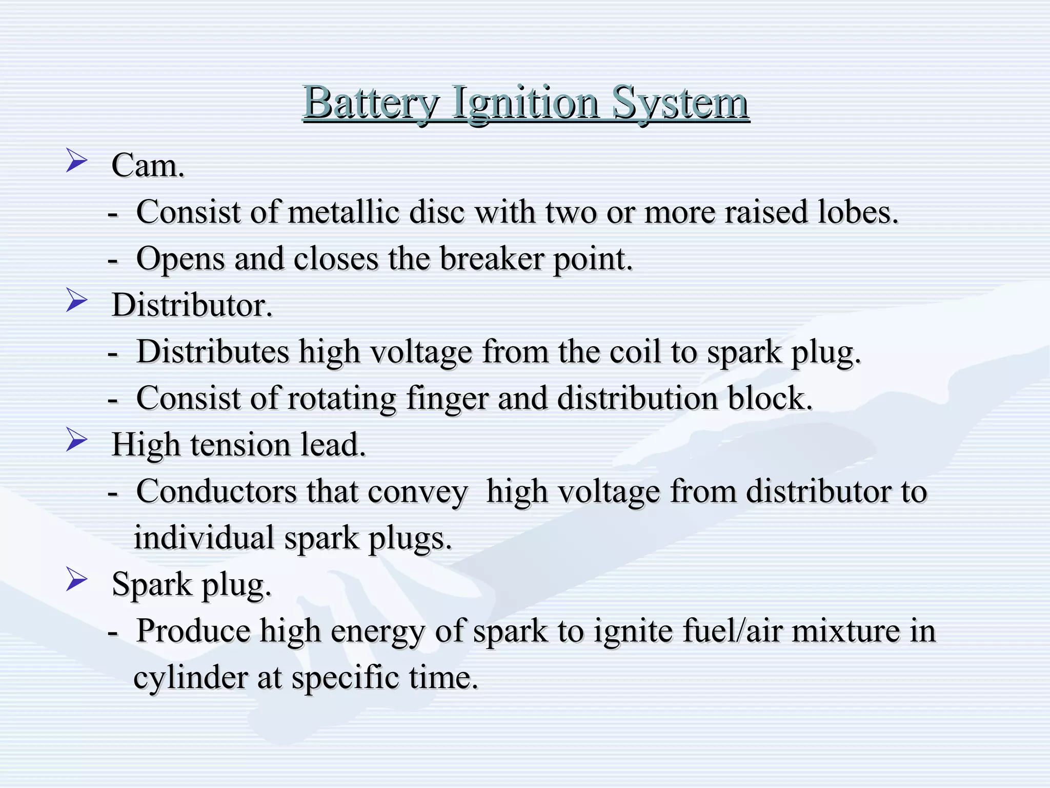
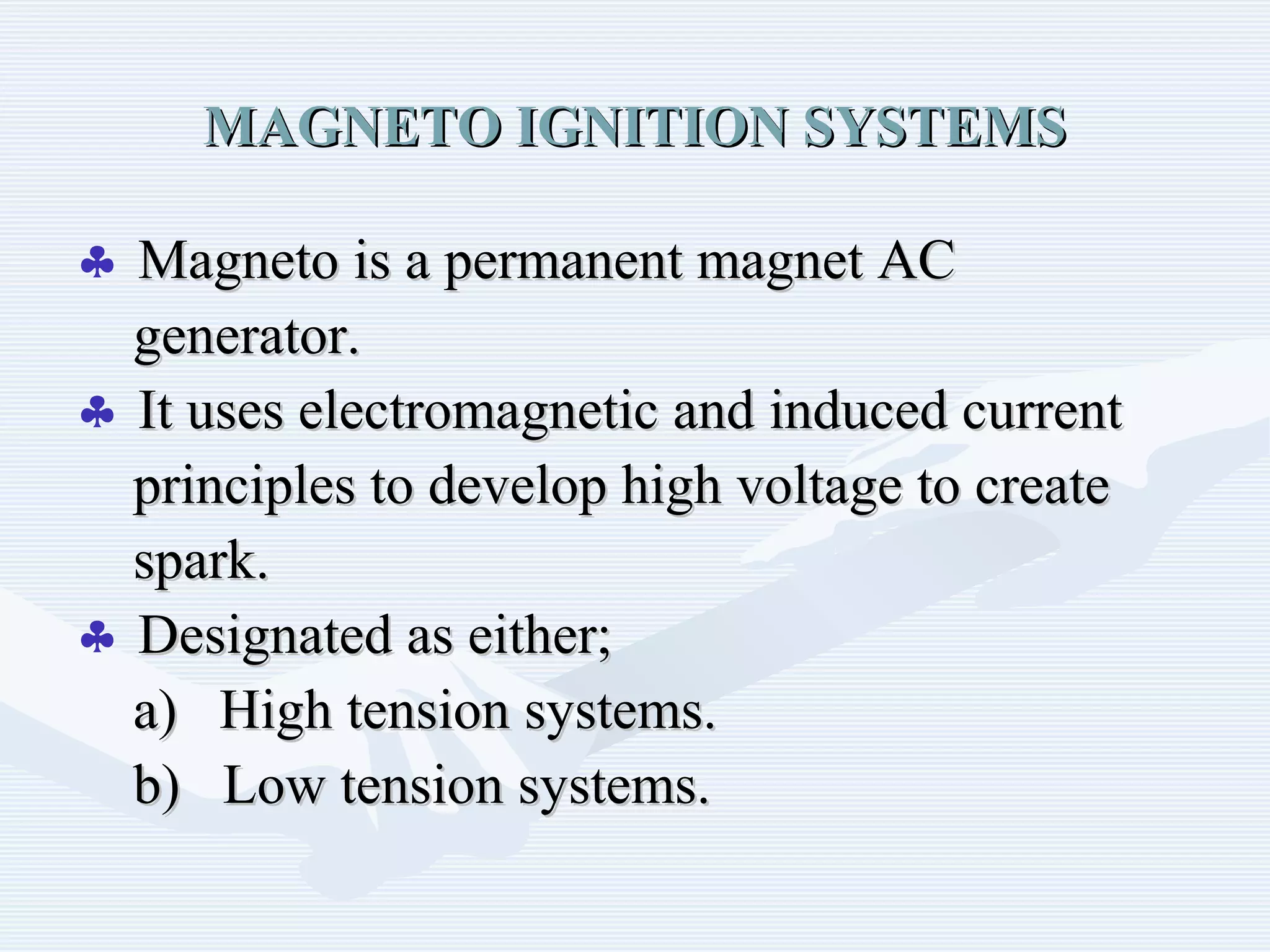
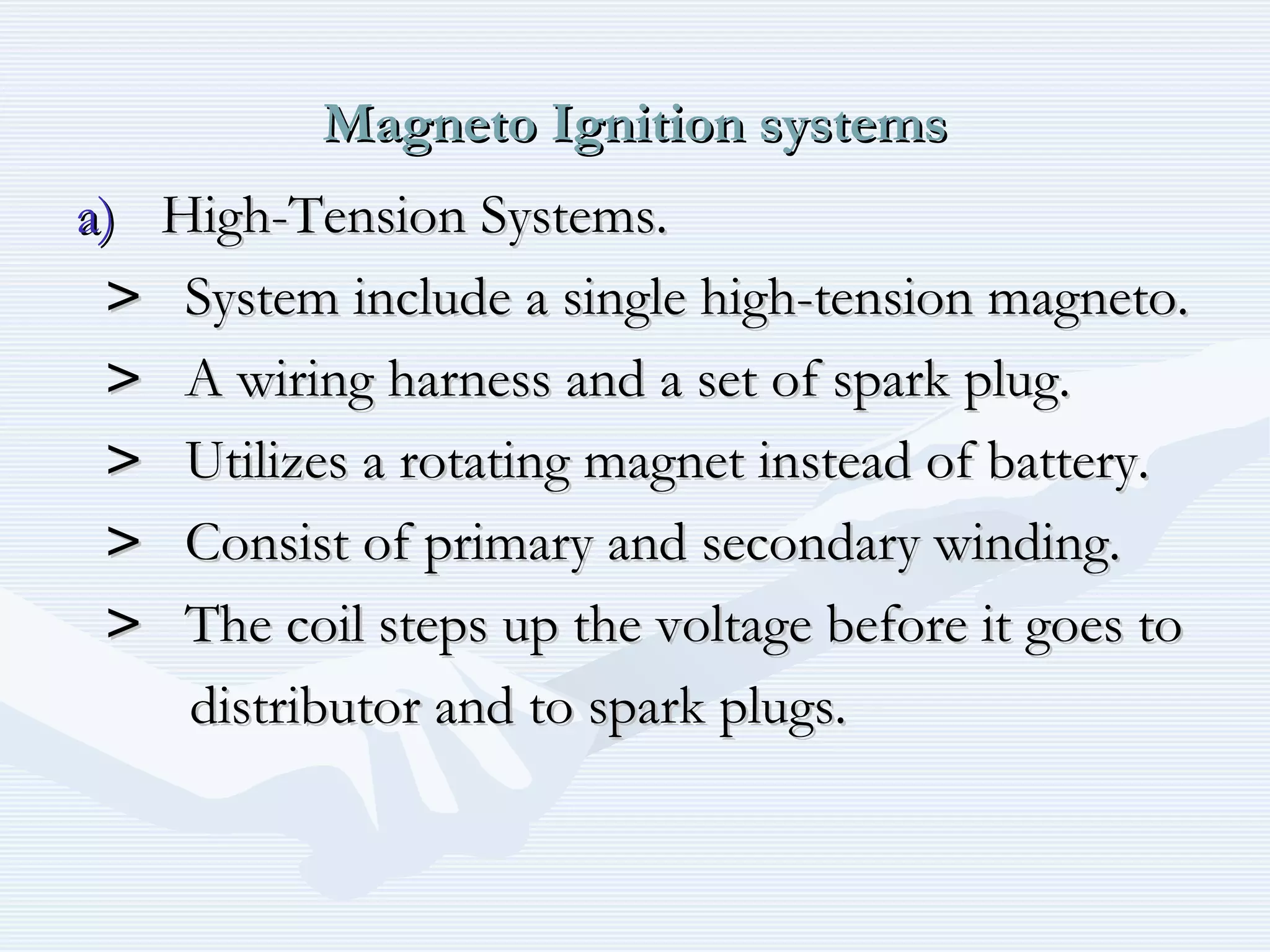
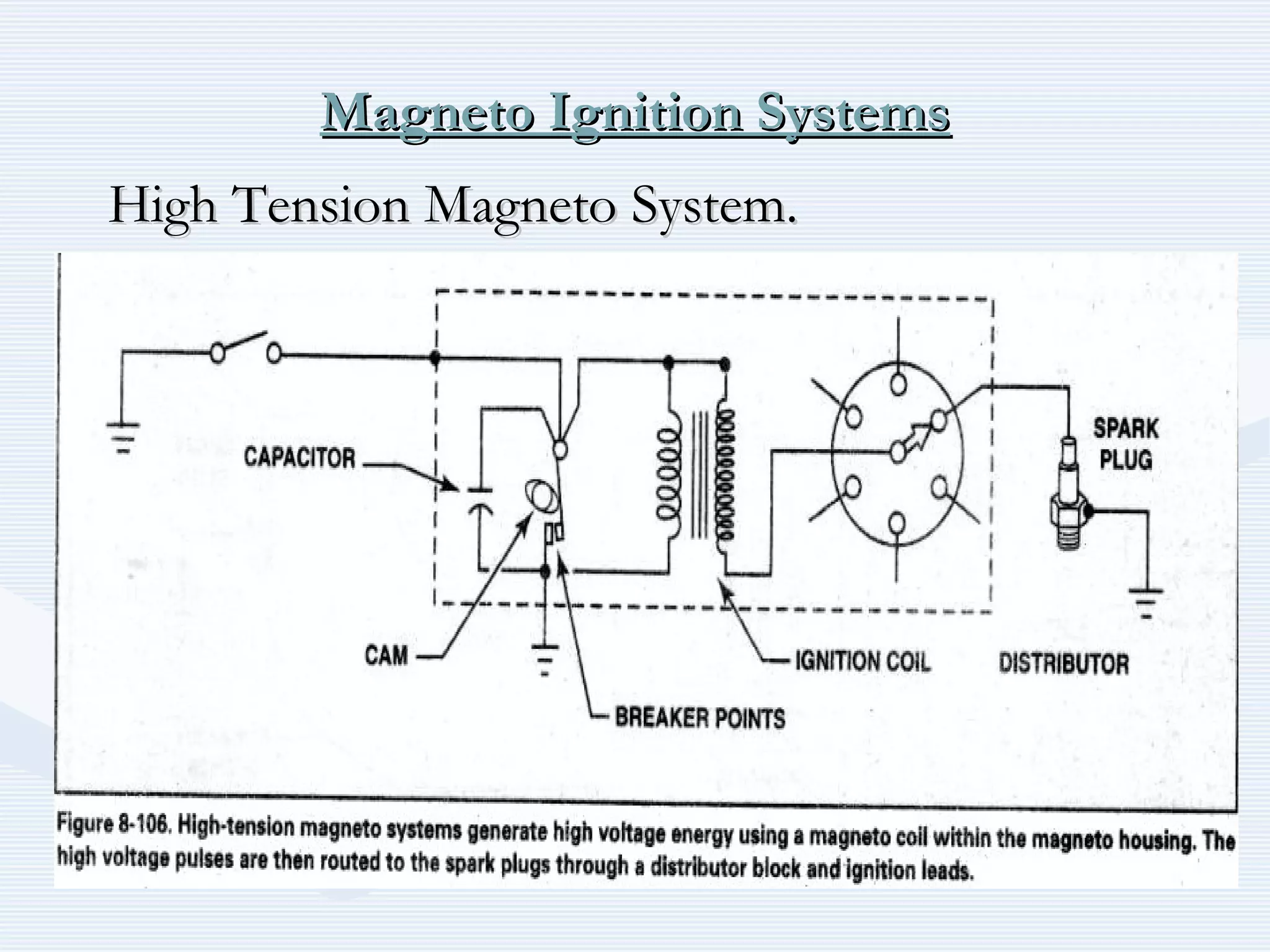
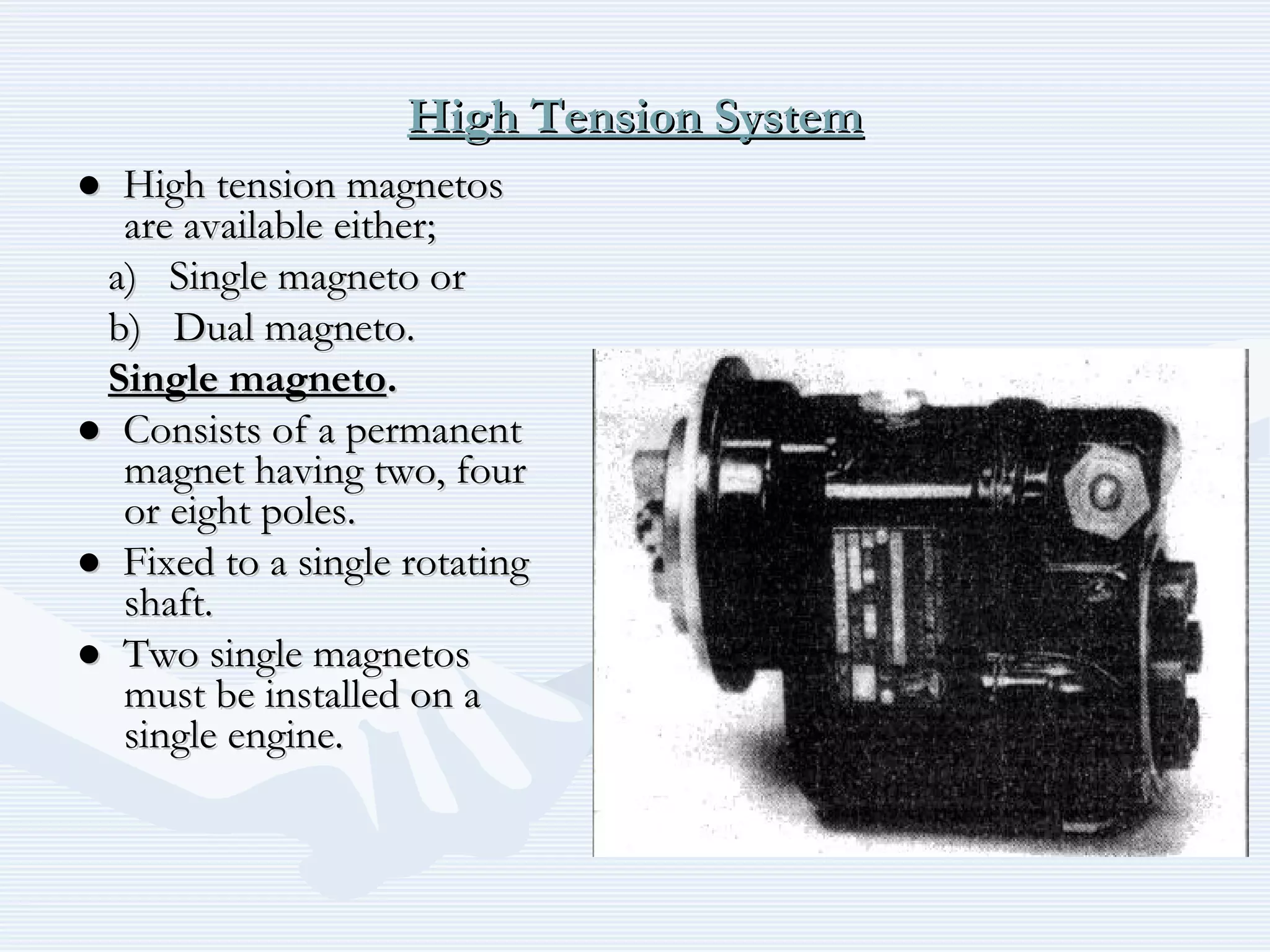
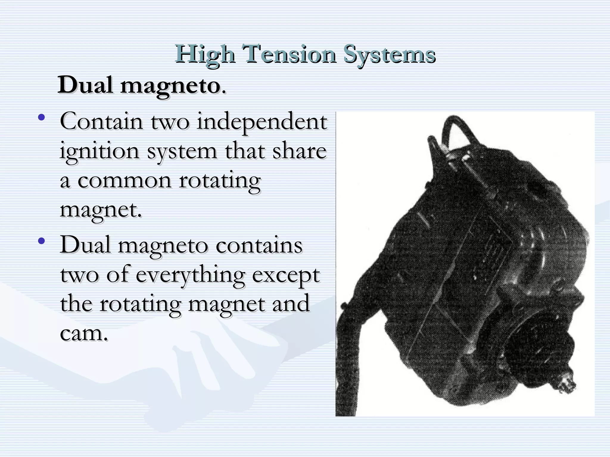
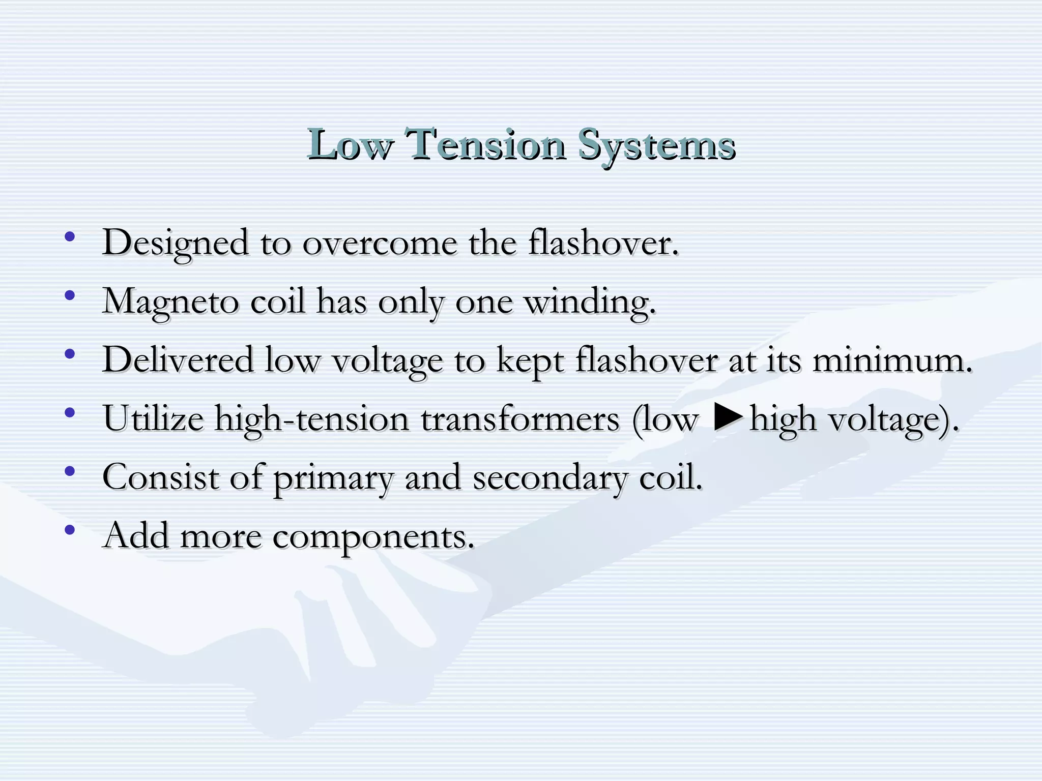
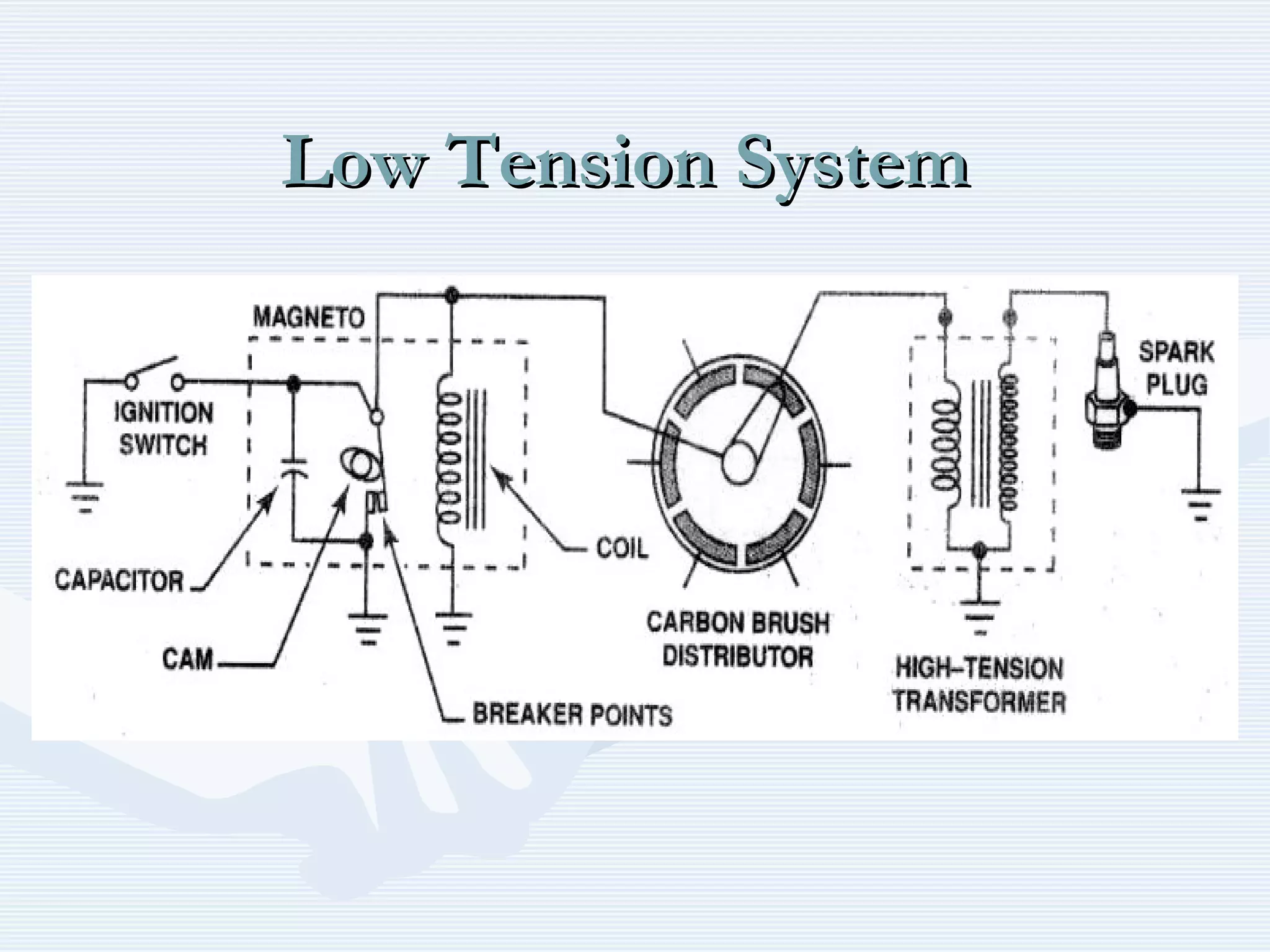
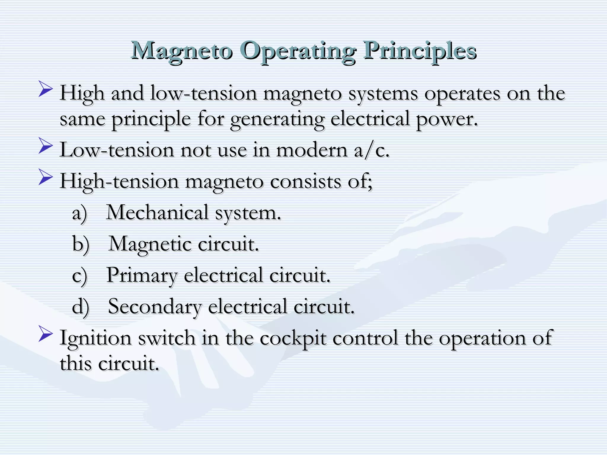
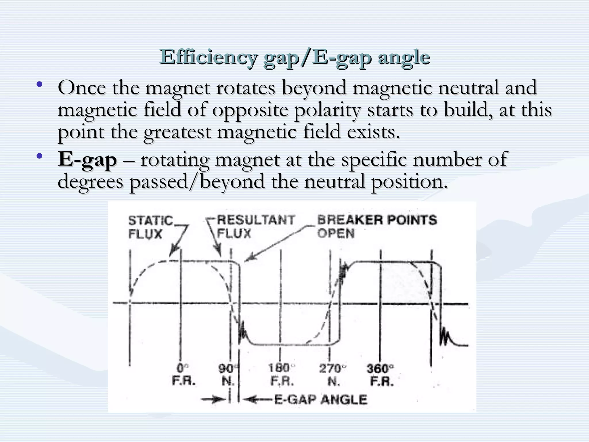
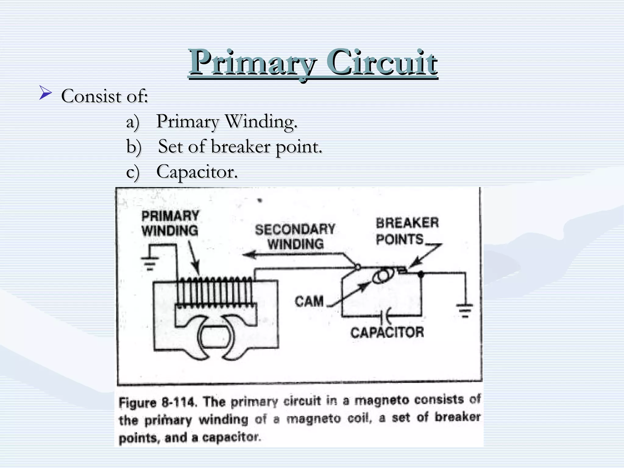
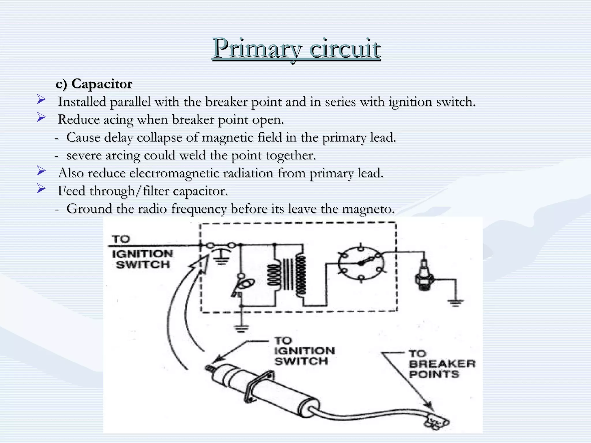
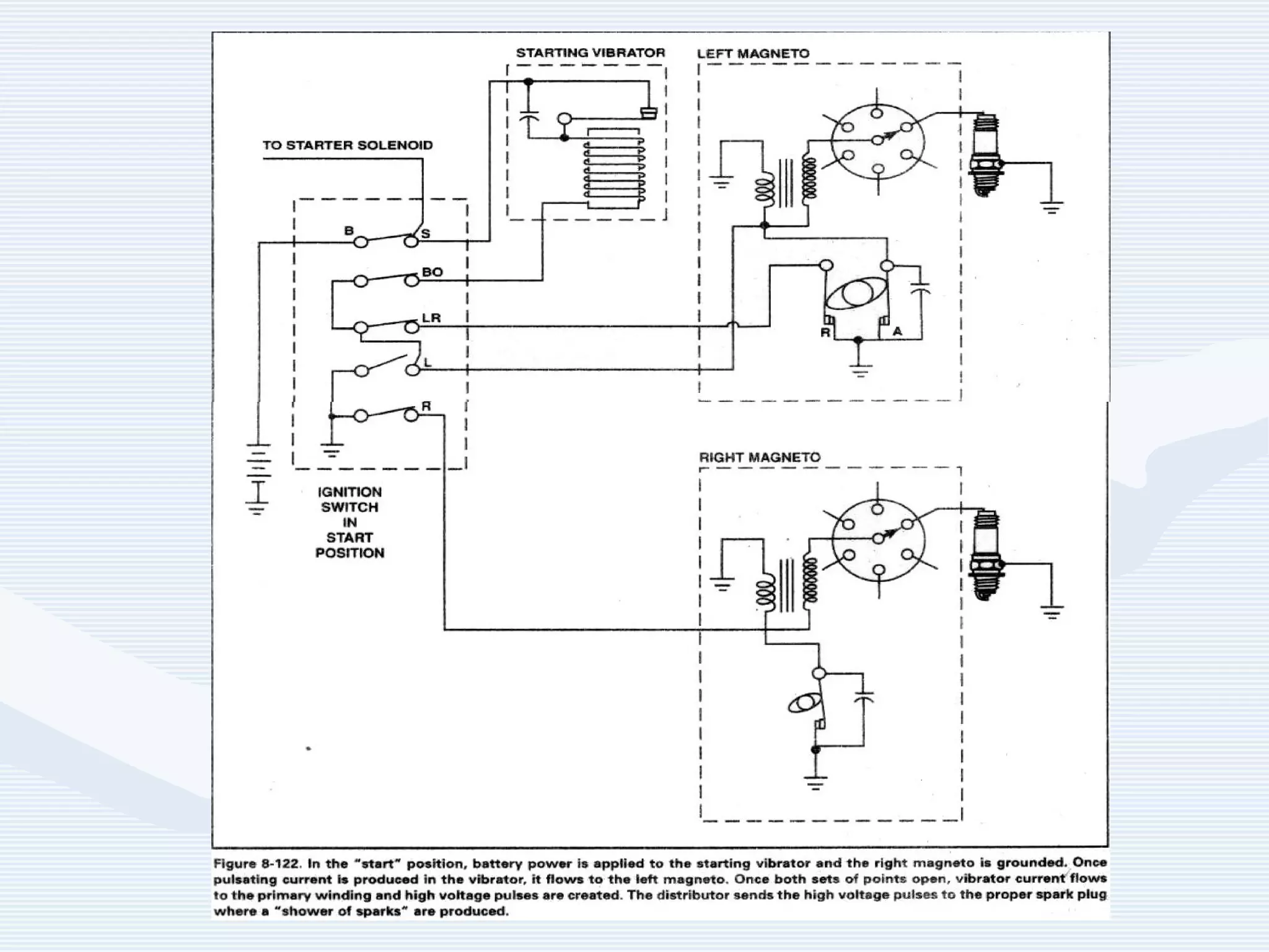

The document discusses reciprocating engine ignition systems. It describes that ignition takes place during the compression stroke in a four-stroke cycle engine. The engine ignition system must reliably deliver a high-voltage spark to each cylinder at the correct time under all operating conditions. Common ignition systems are battery ignition systems which use a battery as an energy source, and magneto ignition systems which use a permanent magnet to generate an alternating current. Battery ignition systems include components like an ignition coil and distributor to generate and distribute the spark. Magneto systems can be high-tension or low-tension, with low-tension systems adding transformers to overcome flashover problems at high altitudes.


