Download to read offline
![SAAD et al. 5 of 17
custom signal processing block written in C++. This will further assist other researchers in experimenting with these
waveforms.
2. We present a case for the use of VR configurations, that is, FBMC-FBMC, OFDM-OFDM, and FBMC-OFDM, for
fine-grained service differentiation in RANaaS. Virtualization layer is implemented in Python within GNU radio.
3. An extensive performance comparison of these VR combinations is carried out while varying the transmit pow-
ers of VRs and analyzing its subsequent effect on the adjacent channel interference that arises between them. We
analyze their performance on the basis of error rate, spectral efficiency, interference power, and computational com-
plexity. This gives valuable insights on the use of different waveform configurations on VRs particularly for their
implementation on base stations that typically have higher transmit power levels.
The rest of the article is structured as follows. The system model is presented in Section 2. Section 3describes the exper-
imental setup. Section 4 presents the experimental results on air-interface virtualization and finally Section 5 concludes
the article.
2 SYSTEM MODEL
This section briefly describes the transmission model for OFDM and FBMC that are used for radio virtualization. By
utilizing these concepts, signal processing blocks are implemented in GNU radio, a detailed explanation for which is
provided in experimental setup section. However, we do not propose modifications to either OFDM or FBMC that are
already mature technologies, nor do we present any theoretical analysis.
2.1 Orthogonal frequency division multiplexing
In OFDM, the baseband discrete time signal can be written as
x[i] =
1
√
N
N−1
∑
n=0
∞
∑
m=−∞
sm,ng[i − mN]ej 2𝜋
N
ni
=
1
√
N
N−1
∑
n=0
∞
∑
m=−∞
sm,n 𝜁m,n, (1)
where 𝜁m,n = g[i − mN]ej 2𝜋
N
ni
is the synthesis basis function, n denotes the subcarrier index, the data transmitted on the
nth subcarrier of the mth OFDM symbol and is expressed as sm, n which is a complex symbol from a M-QAM (quadrature
amplitude modulation) constellation, M is the modulation order, N represent the total number of subcarriers in an OFDM
symbol, 1
√
N
is the power normalization factor, and g is the rectangular window function with its time domain coefficients
defined as
g[i] =
⎧
⎪
⎨
⎪
⎩
1
√
T
if |i| ≤ T
2
0 if |i| > T
2
, (2)
where T = 1
Δf
= NTs is the OFDM symbol duration, Ts is the sampling interval, and Δf is the subcarrier spacing. We can
see that x[i] is the output of an N-point inverse discrete Fourier transform (IDFT) of sm, n. IDFT can be performed using
fast Fourier transform which is a computationally efficient way. To eliminate the inter symbol interference (ISI) and inter
carrier interference (ICI), a CP of length Lcp is added to the OFDM symbol whose length is equal or greater than the
channel delay spread. Although the use of CP ensures ISI- and ICI-free transmission; however, the signal to noise ratio
(SNR) is reduced by a factor 𝛼 = N
N+Lcp
. Adding a CP with OFDM symbol before transmission will transform x with length
Lx to xcp with length Lx + Lcp and is expressed as
xcp = x[Lx − Lcp], … , x[Lx − 1], x[0], … , x[Lx − 1]. (3)](https://image.slidesharecdn.com/ett-201108045522/85/Air-Interface-Virtualization-using-FBMC-and-OFDM-Configurations-5-320.jpg)
![6 of 17 SAAD et al.
The signal after passing through the channel is received by the receiver as y and is given as
y[i] = xcp[i] ∗ h[i] =
Lcp
∑
k=0
h[k]x[i − k]Lx
= xcp[i] ⊗ h[i]. (4)
Note that xcp[i − n] = x[i − k]Lx
for 0 ≤ i ≤ Lx − 1, where [.]Lx
indicates a modulo-Lx operation and ⊗ represents cyclic
convolution. We can see that cyclic prefix transforms the linear convolution of the transmitted signal with the chan-
nel impulse response into circular/cyclic convolution. This circular/cyclic convolution will result in a circulant channel
matrix which is diagonalized by the FFT in the receiver. This diagonalization guarantee flat fading in each subchannel
and single tap equalization is enough to overcome the channel effects.
Assuming a noiseless and distortion-free channel, the estimated symbol ̂sm,n at the receiver output will be same as
the transmitted symbol sm, n if the internal product of the received signal y and the analysis basis function 𝜁m,n = g[i −
mN]e−j 2𝜋
N
ni
constitutes an orthonormal function, that is,
⟨ ∞
∑
i=−∞
g[i − mN]g[i − m′
N]ej 2𝜋
N
(n−n′)(i−
Lx−1
2
⟩
= 𝛿n,n′ 𝛿m,m′ , (5)
where ⟨u, v⟩ is the internal product between u and v and 𝛿m,m′ represents the Kronecker delta.
2.2 Filter bank multicarrier
Contrary to OFDM, each subcarrier in an FBMC system is modulated with a real-valued symbol to satisfy the orthogonal-
ity requirement. To maintain the same data rate as OFDM system without CP, the FBMC system transmit a real symbol
every half symbol duration, that is, T
2
, resulting in so called FBMC/OQAM system.27
This is performed at the transmitter
side where each complex data symbol sm, n, is separated into real/in-phase sI
m,n and imaginary/quadrature phase sQ
m,n com-
ponents. If T represents complex OFDM symbol duration with no CP, then 𝜏0 = T
2
represents the symbol duration of the
real FBMC/OQAM symbol. However, the subcarrier spacing v0 in FBMC/OQAM is same as OFDM, that is, v0 = Δf. Thus
for FBMC/OQAM system we have 𝜏0v0 = 1
2
which means that the density of the subcarriers in time frequency plan is twice
greater in FBMC/OQAM than the conventional OFDM where TΔf = 1. The information carried by one complex-valued
OFDM symbol with duration T is now carried by two real-valued symbols in FBMC/OQAM system each with duration
T
2
. Hence, the spectral efficiency of FBMC/OQAM is same as that of conventional OFDM with no CP.
The discrete time baseband transmitted signal in FBMC/OQAM can be written as
x[i] =
N−1
∑
n=0
∞
∑
m=−∞
am,ng[i − mN∕2]ej 2𝜋
N
n(i−D∕2)
ej𝜙m,n
=
N−1
∑
n=0
∞
∑
m=−∞
am,n 𝜁m,n[i], (6)
where 𝜁m,n[i] = g[i − mN∕2]ej 2𝜋
N
n(i−D∕2)
ej𝜙m,n is the synthesis basis function and am,n ∈ {sI
m,n, sQ
m,n} is a real-valued symbol
which is either the real or imaginary part of the input QAM symbol sm, n. While g[i] represent the well localized prototype
filter. The term D/2 is the delay term that depends on the length of the prototype filter, that is, D = KN − 1. The phase term
𝜙m,n ensures that the phase shift of ±𝜋∕2 is between adjacent pulse amplitude modulation (PAM) symbols along the time
frequency axis and is given as 𝜙m,n = 𝜋
2
(m + n).
Assuming a noiseless and distortion-free channel, the estimated symbol ̂am,n at the receiver output will be same as
the transmitted symbol am, n if the real internal product between the received signal y and the analysis basis function
𝜁m,n[i] = g[i − mN∕2]e−j 2𝜋
N
n(i−D∕2)
ej𝜙m,n constitutes an orthonormal function, that is,
⟨ ∞
∑
i=−∞
g
[
i −
mN
2
]
g
[
i −
m′
N
2
]
ej 2𝜋
N
(n−n′)(i−
Lx−1
2 ej(𝜙m′,n′ −𝜙m,n)
⟩
ℜ
= 𝛿n,n′ 𝛿m,m′ , (7)](https://image.slidesharecdn.com/ett-201108045522/85/Air-Interface-Virtualization-using-FBMC-and-OFDM-Configurations-6-320.jpg)
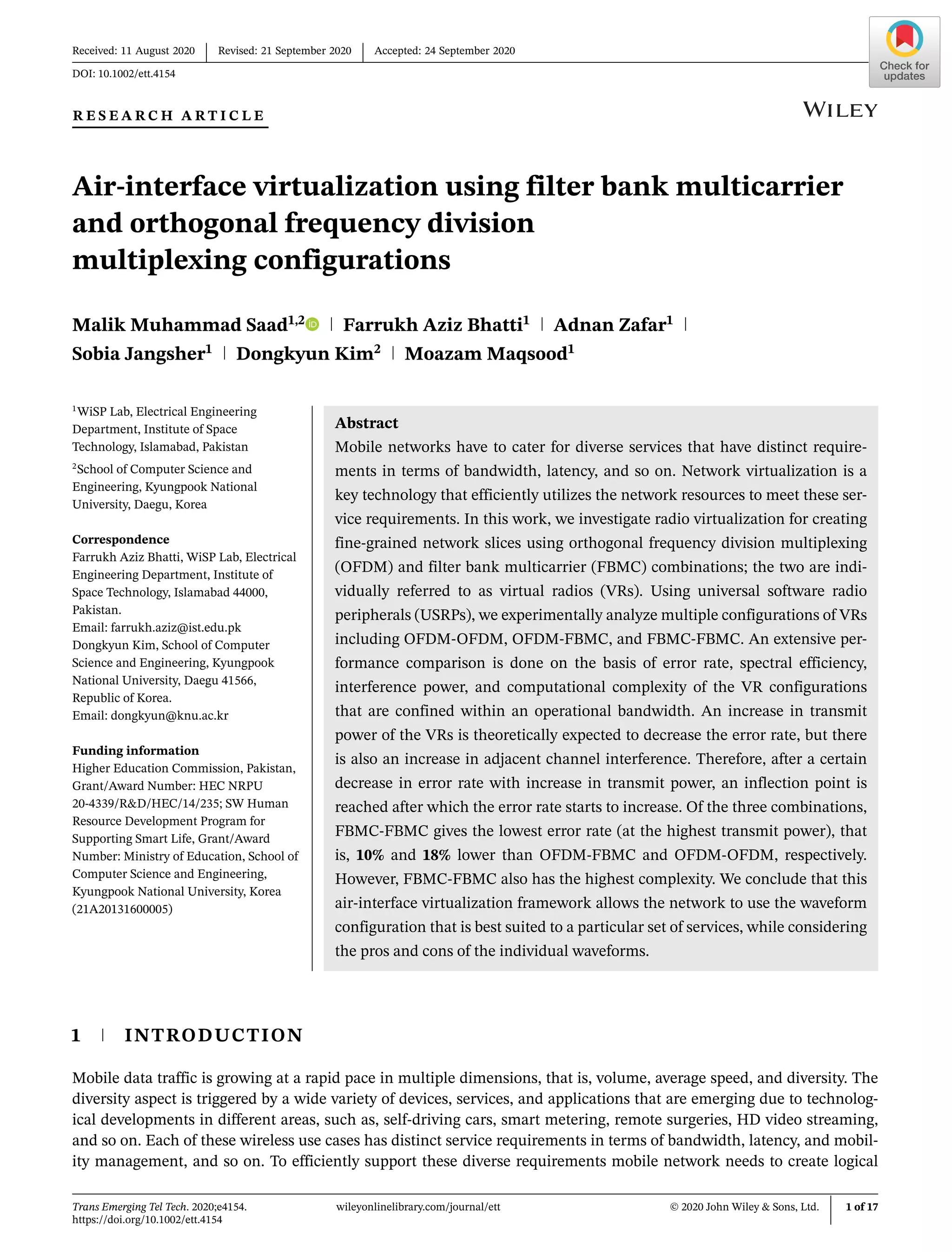
![10 of 17 SAAD et al.
are implemented using IQ samples that are transformed into the frequency domain using FFT module. These sam-
ples are collected individually with respect to the bandwidth of the radio interfaces. Collected samples are then placed
in the same buffer for each VR based on the overall available system bandwidth. Frequency spacing is set between
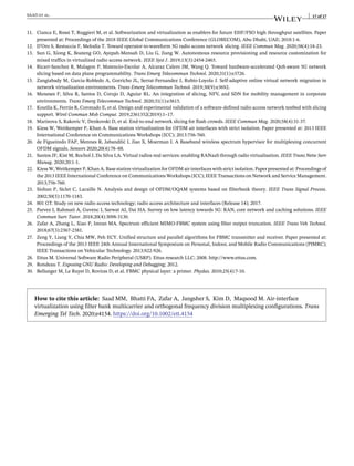
the two VRs before mapping these on to a single composite signal. Algorithm 42 is the pseudocode for the mapping
of VRs.
Algorithm 1. FBMC sample collector
Check if new frame is not too late
if airtime < chunk::low_time then
Dropping frame;
else
Frames Send ++;
if new_samples_needed > sensor_pre_push*sensor_chunk_len then
Too many new samples needed;
else
Check if new chunks have to be appended
if new_samples_needed > 0 then
int new_chunks_needed = (new_samples_needed + chunk::chunk_len - 1) /
chunk::chunk_len;
for <int i=0; i<new_chunks_needed; i++> do
sensor_chunk_vec.push_back(new chunk());
end
else
Return;
end
end
end
Algorithm 2. Polyphase network receive filter
veclen ← veclength;
filterlen ← filterlength;
sizet alig = volk_get_alignment();
filter = (gr_complex*) volk_malloc(filterlen*veclen*sizeof(gr_complex), alig);
gr_complex *buffer = (gr_complex*) volk_malloc(filterlen*veclen*sizeof(gr_complex),
alig);
for <int i=0; i<noutput_items; i++> do
for <int j=0; j<filterlen; j++> do
volk_32fc_x2_multiply_32fc(&buffer[j*veclen], &in[(i+2*j)*veclen], &fil-
ter[j*veclen], veclen);
end
for <int k=1; k<filterleng; k++> do
volk_32f_x2_add_32f((float*) buffer, (const float*) buffer, (const float*)
&buffer[k*veclen], 2*veclen);
end
memcpy(&out[i*veclen], buffer, veclen*sizeof(gr_complex));
end
volk_free(buffer);
return noutput_items;
2
The source code is publically available at GitHub (https://github.com/maiconkist/gr-hydra.git).](https://image.slidesharecdn.com/ett-201108045522/85/Air-Interface-Virtualization-using-FBMC-and-OFDM-Configurations-10-320.jpg)
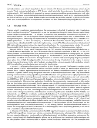
![SAAD et al. 11 of 17
Algorithm 3. FBMC frame extractor
Step 1: Check input items for new frames
for <int i=0; i<noutput_items; i++>
if in0[i*veclen] == 0 then
continue;
for <int j=0; j<log_chann; j++> do
int tau = in0[i*veclen + j*3 + 1];
if tau ≠ veclen then
frames_received ++;
else
Return;
end
end
else
Return;
end
Step 2: Collect frame samples from input items
for <int i=0; i<frame_vec.size(); i++> do
if frame_vec[i]->data_cnt > 0 then
continue;buffer = frame::frame_len - frame_vec[i]->data_cnt;
else
buffer = frame::frame_len;
end
end
memcpy(&frame_vec[i]->data[frame_vec[i]
->data_cnt], &in1[rel_idx], buffer*sizeof(gr_complex)); frame_vec[i]->data_cnt += buffer;
Step 3:Delete frames
for <int i ≤ frame_vec.size()-1; i ≤ 0; i– > do
if frame_vec[i]->data_cnt == frame::frame_len then
delete frame_vec[i];
frame_vec.erase(frame_vec.begin() + i);
else
Return;
end
end
Algorithm 4. VR mapping
BW ← Bandwidth available;
FC ← Center Frequency of Radio;
VR_FC ← Center Frequency of Virtual∕Radio;
Offset = (VR_FC − VRbw∕2.0) − (FC − BW∕2.0);
int temp = BW ∕ fftmlen;
int sc = offset ∕ temp;
sizet fftn = VRbw∕temp;
if sc ≤ 0 || sc ≥ fftmlen then
Cannot allocate subcarriers for VR ;
Return
else
For<; sc < fftmlen; sc++>
if Already allocated then
Return
else
themap.pushback(sc);
themap.size() == fftn;
break;
end
end](https://image.slidesharecdn.com/ett-201108045522/85/Air-Interface-Virtualization-using-FBMC-and-OFDM-Configurations-11-320.jpg)

This research article investigates air-interface virtualization in mobile networks using filter bank multicarrier (FBMC) and orthogonal frequency division multiplexing (OFDM) to create efficient network slices. The study compares various configurations of virtual radios and analyzes performance metrics such as error rate, spectral efficiency, and computational complexity, concluding that the FBMC-FBMC configuration yields the lowest error rate but has the highest complexity. The findings emphasize the importance of selecting appropriate waveform configurations to meet diverse service requirements in mobile network environments.