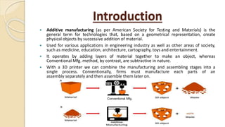
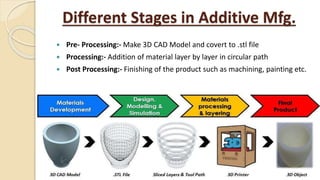
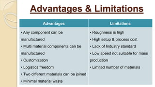
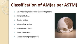
By:-
Sudhir Kumar
Introduction
 Additive manufacturing (as per American Society for Testing and Materials) is the
general term for technologies that, based on a geometrical representation, create
physical objects by successive addition of material.
 Used for various applications in engineering industry as well as other areas of society,
such as medicine, education, architecture, cartography, toys and entertainment.
 It operates by adding layers of material together to make an object, whereas
Conventional Mfg. method, by contrast, are subtractive in nature.
 With a 3D printer we can combine the manufacturing and assembling stages into a
single process. Conventionally, firms must manufacture each parts of an
assembly separately and then assemble them later on.
Conventional Mfg.
Different Stages in Additive Mfg.
 Pre- Processing:- Make 3D CAD Model and covert to .stl file
 Processing:- Addition of material layer by layer in circular path
 Post Processing:- Finishing of the product such as machining, painting etc.
Advantages Limitations
• Any component can be
manufactured
• Multi material components can be
manufactured
• Customization
• Logistics freedom
• Two different materials can be joined
• Minimal material waste
• Roughness is high
• High setup & process cost
• Lack of Industry standard
• Low speed not suitable for mass
production
• Limited number of materials
Advantages & Limitations
Classification of AM(as per ASTM)
1. Vat Photopolymerisation/ Steriolithography
2. Material Jetting
3. Binder jetting
4. Material extrusion
5. Powder bed fusion
6. Sheet lamination
7. Directed energy deposition
1. Vat Photopolymerisation/ Steriolithography
 Laser beam traces a cross-section of the part pattern on the surface of the
liquid resin
 SLA's elevator platform descends
 A resin-filled blade sweeps across the cross section of the part, re-coating
it with fresh material
 Immersed in a chemical bath
 Stereolithography requires the use of supporting structures
2. Material Jetting
 Drop on demand method
 The print head is positioned above build platform
 Material is deposited from a nozzle which moves horizontally across the
build platform
 Material layers are then cured or hardened using ultraviolet (UV) light
 Droplets of material solidify and make up the first layer.
 Platform descends
 Good accuracy and surface finishes
3. Binder Jetting
 A glue or binder is jetted from an inkjet style print head
 Roller spreads a new layer of powder on top of the previous layer
 The subsequent layer is then printed and is stitched to the previous layer
by the jetted binder
 The remaining loose powder in the bed supports overhanging structures
4. Material Extrusion/FDM
 Fuse deposition modelling (FDM)
 Material is drawn through a nozzle, where
it is heated and is then deposited layer by
layer
 First layer is built as nozzle deposits
material where required onto the cross
sectional area.
 The following layers are added on top of
previous layers.
 Layers are fused together upon deposition
as the material is in a melted state.
5. Powder Bed Fusion
 A layer, typically 0.1mm thick of material is spread over the build platform.
 The SLS machine preheats the bulk powder material in the powder bed
 A laser fuses the first layer
 A new layer of powder is spread.
 Further layers or cross sections are fused and added.
 The process repeats until the entire model is created.
6. Sheet Lamination
 Metal sheets are used
 Laser beam cuts the contour of each layer
 Glue activated by hot rollers
7. Directed Energy Deposition
 Consists of a nozzle mounted on a multi axis arm
 Nozzle can move in multiple directions
 Material is melted upon deposition with a laser or electron beam
Latest Research Area
 Additive Manufacturing of Smart components.
 AM of two dissimilar materials.
 AM of ceramics. etc.
Thank you

Additive Manufacturing.pptx

  • 1.
  • 2.
    Introduction  Additive manufacturing(as per American Society for Testing and Materials) is the general term for technologies that, based on a geometrical representation, create physical objects by successive addition of material.  Used for various applications in engineering industry as well as other areas of society, such as medicine, education, architecture, cartography, toys and entertainment.  It operates by adding layers of material together to make an object, whereas Conventional Mfg. method, by contrast, are subtractive in nature.  With a 3D printer we can combine the manufacturing and assembling stages into a single process. Conventionally, firms must manufacture each parts of an assembly separately and then assemble them later on. Conventional Mfg.
  • 3.
    Different Stages inAdditive Mfg.  Pre- Processing:- Make 3D CAD Model and covert to .stl file  Processing:- Addition of material layer by layer in circular path  Post Processing:- Finishing of the product such as machining, painting etc.
  • 4.
    Advantages Limitations • Anycomponent can be manufactured • Multi material components can be manufactured • Customization • Logistics freedom • Two different materials can be joined • Minimal material waste • Roughness is high • High setup & process cost • Lack of Industry standard • Low speed not suitable for mass production • Limited number of materials Advantages & Limitations
  • 5.
    Classification of AM(asper ASTM) 1. Vat Photopolymerisation/ Steriolithography 2. Material Jetting 3. Binder jetting 4. Material extrusion 5. Powder bed fusion 6. Sheet lamination 7. Directed energy deposition
  • 6.
    1. Vat Photopolymerisation/Steriolithography  Laser beam traces a cross-section of the part pattern on the surface of the liquid resin  SLA's elevator platform descends  A resin-filled blade sweeps across the cross section of the part, re-coating it with fresh material  Immersed in a chemical bath  Stereolithography requires the use of supporting structures
  • 7.
    2. Material Jetting Drop on demand method  The print head is positioned above build platform  Material is deposited from a nozzle which moves horizontally across the build platform  Material layers are then cured or hardened using ultraviolet (UV) light  Droplets of material solidify and make up the first layer.  Platform descends  Good accuracy and surface finishes
  • 8.
    3. Binder Jetting A glue or binder is jetted from an inkjet style print head  Roller spreads a new layer of powder on top of the previous layer  The subsequent layer is then printed and is stitched to the previous layer by the jetted binder  The remaining loose powder in the bed supports overhanging structures
  • 9.
    4. Material Extrusion/FDM Fuse deposition modelling (FDM)  Material is drawn through a nozzle, where it is heated and is then deposited layer by layer  First layer is built as nozzle deposits material where required onto the cross sectional area.  The following layers are added on top of previous layers.  Layers are fused together upon deposition as the material is in a melted state.
  • 10.
    5. Powder BedFusion  A layer, typically 0.1mm thick of material is spread over the build platform.  The SLS machine preheats the bulk powder material in the powder bed  A laser fuses the first layer  A new layer of powder is spread.  Further layers or cross sections are fused and added.  The process repeats until the entire model is created.
  • 11.
    6. Sheet Lamination Metal sheets are used  Laser beam cuts the contour of each layer  Glue activated by hot rollers
  • 12.
    7. Directed EnergyDeposition  Consists of a nozzle mounted on a multi axis arm  Nozzle can move in multiple directions  Material is melted upon deposition with a laser or electron beam
  • 13.
    Latest Research Area Additive Manufacturing of Smart components.  AM of two dissimilar materials.  AM of ceramics. etc.
  • 14.