Downloaded 12 times
![Adaptive Control for Laser Transmitter
Feedforward Linearization System
Y. S. Neo,1
S. M. Idrus,1
M. F. Rahmat,2
S. E. Alavi,1
and I. S. Amiri3
1
Photonic Research Laboratory, Faculty of Electrical Engineering, Universiti Teknologi Malaysia,
81310 Johor, Malaysia
2
Control & Instrumentation Engineering Department, Faculty of ElectricalEngineering,
Universiti Teknologi Malaysia, 81310 Johor, Malaysia
3
Photonics Research Centre, Department of Physics, Faculty ofScience, University of Malaya,
50603 Kuala Lumpur, Malaysia
DOI: 10.1109/JPHOT.2014.2335711
1943-0655 Ó 2014 IEEE. Translations and content mining are permitted for academic research only.
Personal use is also permitted, but republication/redistribution requires IEEE permission.
See http://www.ieee.org/publications_standards/publications/rights/index.html for more information.
Manuscript received April 16, 2014; revised June 22, 2014; accepted June 25, 2014. Date of publica-
tion July 8, 2014; date of current version July 14, 2014. This work was supported in part by the Min-
istry of Science, Technology and Innovation through the eScienceFund and in part by the
Administration of the Universiti Teknologi Malaysia (UTM), in particular the Research Management
Centre (RMC), through vote number 06-01-06-SF1148. The work of I. S. Amiri was supported by the
University of Malaya/MOHE under Grant UM.C/625/1/HIR/MOHE/SCI/29. Corresponding author:
S. M. Idrus (e-mail: sevia@fke.utm.my).
Abstract: In this paper, an adaptive control system is employed in a novel implementa-
tion technique of the feed forward linearization system for optical analog communication
systems’ laser transmitter. The adaptive control system applies the Newton trust-region
dogleg algorithm, which is a numerical optimization algorithm, to automatically tune the
adjustment parameters in the feedforward loops to optimize the feed forward system per-
formance and adapt to process variations. At the end of this paper, significant reductions
of over 20 dBm in the third-order inter modulation distortion products have been
achieved for operating frequencies from 5.0 to 5.8 GHz.
Index Terms: Adaptive control system, feedforward linearization, laser transmitter, numerical
optimization, Newton trust-region dogleg.
1. Introduction
While the current researches of Radio over fiber (RoF) technology is focusing on the millimeter
wave frequency range,meaning that external intensity modulation is more prevalent nowadays,
direct modulation of laser diode at lower frequencies such as the ISM band is still an interested
subject because of its simplicity and cost effectiveness [1], [2]. However, in the direct modula-
tion of a laser diode, the dynamic range of the optical fiber links is limited by the nonlinear dis-
tortions generated by laser nonlinearities [3]–[5]. Feedforward linearization is an effective
technique for laser nonlinearity compensation system because of its ability to provide broad-
band distortion reduction at high frequencies, and reductionin all order of distortions regardless
of the laser nonlinear characteristics [6]–[11]. However, feedforward is also a complicated and
sensitive scheme as itinvolves cancellation between 2 signals of almost equal in magnitude and
phase. In order to achieve optimumcancellation, optimizations are needed for the control param-
eters in the feedforward loops. Furthermore, changing operating conditions or process variations
may disrupt the path matching and loop balance [12], [13], which causes the system perfor-
mance to degrade in real time applications. Hence, the feedforward linearization system needs
Vol. 6, No. 4, August 2014 7901910
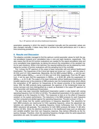
IEEE Photonics Journal Adaptive Feedforward Linearization System](https://image.slidesharecdn.com/6-140817233306-phpapp02/85/Adaptive-Control-for-Laser-Transmitter-Feedforward-Linearization-System-2-320.jpg)
![to be incorporated with adaptive properties in order to maintain its performance for more practi-
cal implementations. This work demonstrates a novel design of feedforward linearization system
for optical analog communication systems’ laser transmitter equipped with an adaptive control
system. Pilot signals are used to guide the adaptation process and the quadrature detection
method is used to detect the pilot signal levels at the output of the feedforward loops. The adap-
tive controller performs the Newton trust region dogleg algorithm, which is a robust algorithm for
equation solving, to simultaneously minimize the in-phase and quadrature signal levels at the
quadrature detector output. The Newton method provides rapid convergence to the solution
point, butthis method is dependent on the initial guess [14]. The trust region method enhances
the Newton method to become more globally convergent by defining a region where the Newton
model is trusted to be a good enough representation of the objective function [15]. Furthermore,
the dogleg method ensures the reduction in objective function for each iteration by using the
combination of the steepest descent step and Newton step to approximate the optimal trajectory
within the trust region [16].
This paper proceeds as follows. Section 2 discusses the feedforward system and the archi-
tecture of adaptive feedforward system. The mathematical analysis of the feedforward loops are
done in Section 3 and the adaptive control algorithm is discussed in Section 4. Sections 5 and 6
show the system setup and results of the developed model, respectively. Finally, Section 7 con-
cludes this paper.
2. Architecture of the Designed System
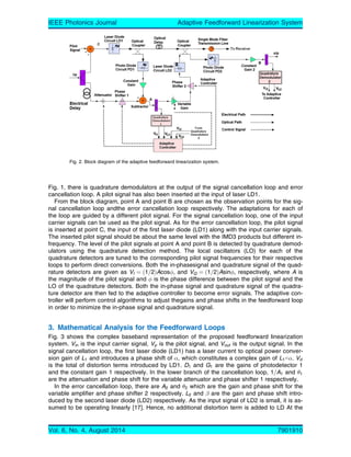
Fig. 1 shows the block diagram of a laser transmitter feedforward linearization system. The sys-
tem consists of 2 loops, where the inner loop is signal cancellation loop and the outerloop is er-
ror cancellation loop. The role of the signal cancellation loop is to acquire the distortions from
the primary laser diode (LD1). On the other hand, the role of the error cancellation loop is to
cancel the distortions from LD1 with the distortion signal obtained from the signal cancellation
loop. As the system involves cancellation between 2 signals of almost equal in terms of magni-
tude and phase, the magnitude and phase parameters in both loops have to be well adjusted so
that the 2 signal match each other. In both the signal cancellation and error cancellation loop,
there are variable attenuator/amplifier and phase shifters which are responsible for amplitude
matching and phase matching, respectively.
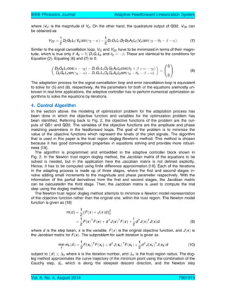
In an adaptive feedforward system, the signals from the chosen observation points in the
open loop feedforward system are used to extract the error signals. The error signals are then
minimized by iteratively updating the amplitude and phase adjustment parameters of the system
in order to achieve adaptation. The architecture of the proposed adaptive feedforward system of
this project is shown in Fig. 2 Compared to the open loop feedforward linearization system in
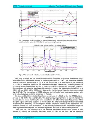
Fig. 1. Block diagram of feedforward linearization system.
Vol. 6, No. 4, August 2014 7901910
IEEE Photonics Journal Adaptive Feedforward Linearization System](https://image.slidesharecdn.com/6-140817233306-phpapp02/85/Adaptive-Control-for-Laser-Transmitter-Feedforward-Linearization-System-3-320.jpg)
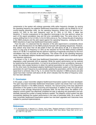
![are the gain and phase shift intro-
duced by the second laser diode (LD2) respectively. As the input signal of LD2 is small, it is as-
sumed to be operating linearly [17]. Hence, no additional distortion term is added to LD At the
Fig. 2. Block diagram of the adaptive feedforward linearization system.
Vol. 6, No. 4, August 2014 7901910
IEEE Photonics Journal Adaptive Feedforward Linearization System](https://image.slidesharecdn.com/6-140817233306-phpapp02/85/Adaptive-Control-for-Laser-Transmitter-Feedforward-Linearization-System-5-320.jpg)

The paper presents an adaptive control system for a feedforward linearization technique used in optical analog communication systems' laser transmitters. Utilizing the Newton Trust-Region Dogleg algorithm, it dynamically optimizes control parameters to mitigate nonlinear distortions, achieving significant performance enhancements, including over 20 dBm reduction in third-order intermodulation distortion. The novel system adapts to variations in operating conditions, making it more effective for real-time applications.


![[IJET-V1I2P9] Authors :Ikdeep Kaur, Harjit Singh, Anu Sheetal](https://cdn.slidesharecdn.com/ss_thumbnails/ijet-v1i2p9-150506100051-conversion-gate02-thumbnail.jpg?width=640&height=640&fit=bounds)


