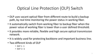
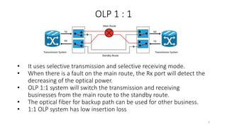
Comprehensive Presentation on Optical Line
Protection Switch (OLP) and Active Fiber
Monitoring System
Engineer Subash Chandra Pakhrin
Backbone Transmission Directorate
Nepal Telecom, Kathmandu Nepal
+977 - 9852050900
1
Optical Line Protection (OLP) Switch
• OLP uses vacant optical fiber from different route to build a backup
path, by real time monitoring the power status in working fiber.
• It automatically switch from working fiber to backup fiber when the
power value of working fiber is lower than a user defined threshold.
• It provides more reliable, flexible and high secure optical transmission
network.
• It is widely used for protecting backbone and important business line.
• Two different kinds of OLP
• OLP 1 : 1
• OLP 1 + 1
2
OLP 1 : 1
• It uses selective transmission and selective receiving mode.
• When there is a fault on the main route, the Rx port will detect the
decreasing of the optical power.
• OLP 1:1 system will switch the transmission and receiving
businesses from the main route to the standby route.
• The optical fiber for backup path can be used for other business.
• 1:1 OLP system has low insertion loss
3
Insertion Loss
• Insertion loss measures the amount of energy that is lost as the signal
arrives at the receiving end of the optical link.
• It quantifies the effect of the resistance the cabling link offers to the
transmission of the electrical signals.
• Excessive insertion loss can also be caused by poorly terminated
connectors / plugs.
• A poor connection can add significant insertion loss.
• However, impurities in the copper cable can also cause insertion
loss failures.
4
OLP 1 + 1
• OLP 1 + 1 system uses dual transmission and selective receiving.
• In OLP 1+1, the optical power from transmitter are divided with a
split ratio of 50:50 on the main route and the standby route, which
means both the main and standby routes are in use no matter
whether there is a fault in the main route
• While for Rx, the optical signal with better quality will be selected.
The advantage of OLP 1+1 system is fast switching and low cost.
• Larger insertion loss compared with OLP 1:1 system. 5
OLP Equipment outlook
6
OLP Equipment application example
7
OLP brief Specifications
• Working wavelength 1310 and 1550 nm.
• Switching time 1 : 1 < 35 ms
• Switching time 1 + 1 < 15 ms
• Optical connector SC / pc
• Transparent transmission
• Passive Device
8
Query
• the optical power – 5.0 dBm from transmitter are divided with a split
ratio of 50:50 on the main route and the standby route. How much
optical power do you receive in each route?
9
SC – UPC (Use it)
SC – APC (Don’t Use it)
10
Active Fiber Monitoring System
• Its preliminary function is same as OTDR.
• It provide the geographical accurate information where the fiber has
been broken.
• The OTDR works on 1625 nm range.
• While the common traffic window are 1550 nm and 1310 nm.
11
Active Fiber Monitoring System
12
Active Fiber Monitoring System
• OTDR are commonly known to network operators as portable units,
but EXFO also integrates them in rackmount equipment along with
optical switch and controller units.
• These are used to perform on demand troubleshooting of any fiber
connecting to the equipment, whether it transports live traffic or not.
• Routine maintenance tests can therefore be schedule and automated
to dramatically simplify this process.
13
Active Fiber Monitoring System
14
Apposite Attribute of AFMS
• It reduce support and maintenance related expenses.
• Dark fiber testing and monitoring for any fiber cable network
• In service, in band CWDM testing and monitoring
• In service, out of band 1625 nm or 1650 nm testing and monitoring
• Stand alone, fully autonomous test equipment
• External 1xn optical switch (up to 128 ports)
• Remotely controlled optical switch unit
• Distributed client server application with central management
• Reporting engine based on alarm duration and fiber downtime
• Network documentations on GIS platform with fault on map
• Water/humidity sensors to be located into splice enclosure
• Integration with network inventory/GIS solutions
• Integration with fault or work ticket management system(s)
15
Fiber Monitoring Topology, In-service and
Dark Fiber Monitoring
16
Filter WDM or FWDM
• Filter-based Wavelength Division Multiplexer is based on the mature
membrane filter technology, with a wide channel bandwidth, low insertion
loss, high channel isolation degrees and high environmental stability and
reliability.
• The device combines or separates light at different wavelengths in a wide
wavelength range.
• These passive optical thin film filters systems are arranged to process
specific wavelengths in and out of the transport stream.
• As these are optical devices they can be used for both multiplexing and de-
multiplexing or both.
• The process of filtering the wavelengths can be performed with prisms, but
more common technologies used are thin film filters, dichroic filters or
interference filters which are used to selectively reflect a single wavelength
of light, but pass all others transparently.
17
Network Quality Monitoring System (NQMS)
18
Alerting of Active Fiber Monitoring System
19
Remote Terminal Unit 720 Software
20
Feature Advantage Benefit
• Learning Function
• 10 sec test per port
• 50 dB version, Ultra Long Haul Fiber Coverage – 250 Km monitoring
• Assessments of your network aging process through yearly
measurement comparisons
• Continuously updated inventory as the OTDR explores your network
• Up to date health status for specific regions or the entire network
21
References:
• http://www.fiber-optic-tutorial.com/optical-line-protection-system.html
• http://www.optic-
switch.com/P/Optical_Line_Protection_System(OLP).html
• https://www.google.com.np/search?q=insertion+loss&oq=insertion+loss&
aqs=chrome.0.0l6.2695j0j4&sourceid=chrome&ie=UTF-8
• http://www.flukenetworks.com/knowledge-base/dtx-
cableanalyzer/attenuation-insertion-loss-measurement-and-testing-dtx
• http://www.khrista.co.id/fiber-network-monitoring-and-management/
• http://www.crony.rs/files/File/Ostalo/NQMSfiber%20Presentation.pdf
• http://files.ekraninfo.com/infocenter/Catalogues%20&%20DS/FO%20moni
toring%20NQMS/NQMSfiber-angHR.pdf
• https://community.fs.com/blog/filter-based-wdm.html
22
Thank You
23

Optical line protection switch and Active Fiber Monitoring System

  • 1.
    Comprehensive Presentation onOptical Line Protection Switch (OLP) and Active Fiber Monitoring System Engineer Subash Chandra Pakhrin Backbone Transmission Directorate Nepal Telecom, Kathmandu Nepal +977 - 9852050900 1
  • 2.
    Optical Line Protection(OLP) Switch • OLP uses vacant optical fiber from different route to build a backup path, by real time monitoring the power status in working fiber. • It automatically switch from working fiber to backup fiber when the power value of working fiber is lower than a user defined threshold. • It provides more reliable, flexible and high secure optical transmission network. • It is widely used for protecting backbone and important business line. • Two different kinds of OLP • OLP 1 : 1 • OLP 1 + 1 2
  • 3.
    OLP 1 :1 • It uses selective transmission and selective receiving mode. • When there is a fault on the main route, the Rx port will detect the decreasing of the optical power. • OLP 1:1 system will switch the transmission and receiving businesses from the main route to the standby route. • The optical fiber for backup path can be used for other business. • 1:1 OLP system has low insertion loss 3
  • 4.
    Insertion Loss • Insertionloss measures the amount of energy that is lost as the signal arrives at the receiving end of the optical link. • It quantifies the effect of the resistance the cabling link offers to the transmission of the electrical signals. • Excessive insertion loss can also be caused by poorly terminated connectors / plugs. • A poor connection can add significant insertion loss. • However, impurities in the copper cable can also cause insertion loss failures. 4
  • 5.
    OLP 1 +1 • OLP 1 + 1 system uses dual transmission and selective receiving. • In OLP 1+1, the optical power from transmitter are divided with a split ratio of 50:50 on the main route and the standby route, which means both the main and standby routes are in use no matter whether there is a fault in the main route • While for Rx, the optical signal with better quality will be selected. The advantage of OLP 1+1 system is fast switching and low cost. • Larger insertion loss compared with OLP 1:1 system. 5
  • 6.
  • 7.
  • 8.
    OLP brief Specifications •Working wavelength 1310 and 1550 nm. • Switching time 1 : 1 < 35 ms • Switching time 1 + 1 < 15 ms • Optical connector SC / pc • Transparent transmission • Passive Device 8
  • 9.
    Query • the opticalpower – 5.0 dBm from transmitter are divided with a split ratio of 50:50 on the main route and the standby route. How much optical power do you receive in each route? 9
  • 10.
    SC – UPC(Use it) SC – APC (Don’t Use it) 10
  • 11.
    Active Fiber MonitoringSystem • Its preliminary function is same as OTDR. • It provide the geographical accurate information where the fiber has been broken. • The OTDR works on 1625 nm range. • While the common traffic window are 1550 nm and 1310 nm. 11
  • 12.
  • 13.
    Active Fiber MonitoringSystem • OTDR are commonly known to network operators as portable units, but EXFO also integrates them in rackmount equipment along with optical switch and controller units. • These are used to perform on demand troubleshooting of any fiber connecting to the equipment, whether it transports live traffic or not. • Routine maintenance tests can therefore be schedule and automated to dramatically simplify this process. 13
  • 14.
  • 15.
    Apposite Attribute ofAFMS • It reduce support and maintenance related expenses. • Dark fiber testing and monitoring for any fiber cable network • In service, in band CWDM testing and monitoring • In service, out of band 1625 nm or 1650 nm testing and monitoring • Stand alone, fully autonomous test equipment • External 1xn optical switch (up to 128 ports) • Remotely controlled optical switch unit • Distributed client server application with central management • Reporting engine based on alarm duration and fiber downtime • Network documentations on GIS platform with fault on map • Water/humidity sensors to be located into splice enclosure • Integration with network inventory/GIS solutions • Integration with fault or work ticket management system(s) 15
  • 16.
    Fiber Monitoring Topology,In-service and Dark Fiber Monitoring 16
  • 17.
    Filter WDM orFWDM • Filter-based Wavelength Division Multiplexer is based on the mature membrane filter technology, with a wide channel bandwidth, low insertion loss, high channel isolation degrees and high environmental stability and reliability. • The device combines or separates light at different wavelengths in a wide wavelength range. • These passive optical thin film filters systems are arranged to process specific wavelengths in and out of the transport stream. • As these are optical devices they can be used for both multiplexing and de- multiplexing or both. • The process of filtering the wavelengths can be performed with prisms, but more common technologies used are thin film filters, dichroic filters or interference filters which are used to selectively reflect a single wavelength of light, but pass all others transparently. 17
  • 18.
  • 19.
    Alerting of ActiveFiber Monitoring System 19
  • 20.
    Remote Terminal Unit720 Software 20
  • 21.
    Feature Advantage Benefit •Learning Function • 10 sec test per port • 50 dB version, Ultra Long Haul Fiber Coverage – 250 Km monitoring • Assessments of your network aging process through yearly measurement comparisons • Continuously updated inventory as the OTDR explores your network • Up to date health status for specific regions or the entire network 21
  • 22.
    References: • http://www.fiber-optic-tutorial.com/optical-line-protection-system.html • http://www.optic- switch.com/P/Optical_Line_Protection_System(OLP).html •https://www.google.com.np/search?q=insertion+loss&oq=insertion+loss& aqs=chrome.0.0l6.2695j0j4&sourceid=chrome&ie=UTF-8 • http://www.flukenetworks.com/knowledge-base/dtx- cableanalyzer/attenuation-insertion-loss-measurement-and-testing-dtx • http://www.khrista.co.id/fiber-network-monitoring-and-management/ • http://www.crony.rs/files/File/Ostalo/NQMSfiber%20Presentation.pdf • http://files.ekraninfo.com/infocenter/Catalogues%20&%20DS/FO%20moni toring%20NQMS/NQMSfiber-angHR.pdf • https://community.fs.com/blog/filter-based-wdm.html 22
  • 23.

Editor's Notes

  • #3 They uses different methods to secure the optical communication networks
  • #6 This OLP 1+1 system is suggested to be used with short-distance optical lines with large surplus.