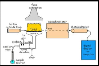
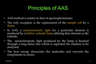
Atomic Absorption
Spectrophotometer (AAS)
Overview of AA
spectrometer.
Light Source Detector
Sample
Compartment
8/29/2023 2
8/29/2023 3
8/29/2023 4
Introduction
• AAS is a technique used for determining the concentration of a
particular metal element within a sample.
• AAS is used to analyse the concentration of over 62 different
metals in a solution.
• AAS is a method of analysis based on absorption of radiation by
atoms when a solution of metallic salt is aspirated (drawing)
into a flame.
• Only a drop of sample needed
• The metals need not be removed from other components.
• Sensitive in the ppm range
8/29/2023 5
Principles of AAS
• AAS method is similar to that of spectrophotometer.
• The only exception is the replacement of the sample cell by a
flame.
• In AAS, a monochromatic light for a particular element is
produced by a hollow cathode lamp utilizing that element as the
cathode.
• The monochromatic light produced by the lamp is beamed
through a long flame into which is aspirated the solution to be
analysed.
• The heat energy dissociates the molecules and converts the
components to atoms.
8/29/2023 6
• At flame temperature, some atoms in the solution are activated,
but most of the atoms are remain in the ground state.
• The ground state atoms of the same element as in the hollow
cathode cup absorb their own resonance (reflected) lines.
• The amount of light absorbed varies directly with their
concentration in the flame.
• The transmitted light that is not absorbed reaches the
monochromator.
• The monochromator passes only the wavelengths close to the
resonance lines of the particular element to be analysed.
• Then the transmitted light strikes a detector and the decrease in
transmitted light is measured.
8/29/2023 7
Components of AAS
• The components of an AAS are
1. Hollow cathode lamp
2. Beam chopper
3. The flame or furnace
4. Nebulizer
5. Monochromator
6. Detector
7. Amplifier.
8/29/2023 8
8/29/2023 9
1. Hollow Cathode Lamp
• The most widely used light source is the hollow cathode lamp.
• These lamps are designed to emit the atomic spectrum of a
particular element, and specific lamps are selected for use
depending on the element to be determined.
8/29/2023 10
 The cathode of the lamp is a hollow-out cylinder of
the metal whose spectrum is to be produced.
 Each analyzed element requires a different lamp.
 The anode and cathode are sealed in a glass
cylinder normally filled with either neon or argon
at low temperature.
 At the end of the glass cylinder is window
transparent to the emitted radiation.
8/29/2023 11
• The cathode lamps are stored
in a compartment inside the
AA spectrometer.
• The specific lamp needed for a
given metal analysis is rotated
into position for a specific
experiment.
8/29/2023 12
8/29/2023 13
Sputtering
• When an electrical potential is
applied between the anode and
cathode, some of the fill gas atoms
are ionized.
• The positively charged fill gas ions
accelerate through the electrical
filed (gather in a line) to collide
with the negatively charged
cathode and dislodge individual
metal atoms in a process called
sputtering.
8/29/2023 14
Excitation and Emission
• Then the sputtered metal atoms are
elevated to an excited state.
• When the atoms return to the ground
state, the characteristic line spectrum
(light) of that atom is emitted.
• Then the emitted light is directed at the
flame where unexcited atoms of the
same element absorb the radiation and
are themselves raised to the excited
state.
• Then the absorbance is measured.
8/29/2023 15
8/29/2023 16
2. Beam chopper
• In AAS, the hollow cathode lamp and flame are light emitting
source.
• The phototube responds to radiation from the hollow cathode
lamp as well as flame.
• This will create interference in absorption measurement.
• This problem is corrected by a beam chopper.
8/29/2023 17
• Beam chopper is a motor
driven device that has open
and solid (or mirrors in some
cases) alternating regions.
• One half of their rotation, i.e.,
open region, permits the
beam obtained from lamp to
pass through.
• During the other half of their
rotation, i.e., mirror region,
the beam is reflected and not
allowed to pass through.
8/29/2023 18
Function of the Chopper
 When the incident beam hits the solid surface, the beam is blocked and the
detector is only read the emitted signal from the flame.
 As the chopper rotates to the open surface and the beam emerges to the
detector.
 Now the detector signal is the sum of the transmitted light signal plus that
emitted from the flame.
 The signal processor is able to subtract the first signal from the second-one,
thus excluding the signal from the emission in flames.
 Signal – 1 (blocked beam) = Pe
 Signal – 2 (transmitted beam) = P + Pe
 Overall difference signal = (P + Pe) – Pe = P (corrected signal)
 This correction method for background emission in flame is called source
modulation.
8/29/2023 19
3. The flame / Burner system
 The third unique component in the system is the burner,
through which the sample is introduced. The burner consists of
three parts, namely,
 nebulizer,
 premix chamber and
 burner head.
8/29/2023 20
Nebulizer
 Suck up liquid sample at a
controlled rate
 Create a fine aerosol for
introduction into the flame
 Mix the aerosol and fuel
and oxidant thoroughly
for introduction into the
flame.
8/29/2023 21
8/29/2023 22
8/29/2023 23
8/29/2023 24
• Sample solution is aspirated
through a nebulizer and
sprayed as a fine aerosol into
the mixing chamber.
• The design of the nebulizer is
to limit the size of the
atomized sample introduced
to the flame to a very small
size (~ 5 – 10nm).
• Droplets larger than this are
stopped by spoilers and end
up flowing to waste.
8/29/2023 25
Premix Chamber
• The nebulizer chamber / premix
chamber thoroughly mixes
acetylene (the fuel) and oxidant (air
or nitrous oxide) and by doing so,
creates a negative pressure at the
end of the small diameter, plastic
nebulizer tube.
• This negative pressure acts to suck
(uptake) liquid samples up the tube
and into the nebulizer chamber, a
process called aspiration.
8/29/2023 26
• A small glass impact bead and / or a fixed impeller inside the
chamber create a heterogeneous mixer of gas (fuel + oxidant)
and suspended aerosol (finely dispersed sample).
• This mixture flows immediately into the burner head where it
burns a smooth, laminar flame evenly distributed along a
narrow slot in the well-machined metal burner.
• Liquid sample not flowing into the flame collects on the bottom
of the nebulizer chamber and flows by gravity through a waste
tube to a glass waste container.
• For some elements that form refractory oxides (molecules hard
to break down in the flame) nitrous oxide (N2O) needs to be
used instead of air (78% N2 + 21% O2) for the oxidant.
• In that case, a slightly different burner head with a shorter
burner slot length is used.
8/29/2023 27
Laminar burner
• The mixture of gases and sample is
directed into the burner head and
flame.
• The burner is a specially one for
AAS.
• It has a long, flat topped head
positioned directly below and
parallel to the beam of light from
the lamp.
• The gases flow through a 10cm
long slot at the top of the burner
head so that a long, thin curtain of
flame is produced.
8/29/2023 28
 The two holes, left and right,
are where the light beam enters
and leaves after passing
through the flame.
 The dark place at the top is a
stain from the heat of the flame.
8/29/2023 29
 The light from the hollow cathode lamp
passes through the full 10cm length of
the flame, greatly enhancing the
absorption of light by the ground state
atoms in the flame.
 The narrowness of the slot also
concentrates the atoms and results in
greater efficiency of light absorption.
• Burner head is made up of solid
titanium which is corrosion resistant
and free of most of the elements
commonly determined by absorption.
8/29/2023 30
Job of the flame
• Destroy any analyte ions and
breakdown complexes.
• Create atoms (the elemental
form) of the element of
interest. FeO, CuO, ZnO etc.
8/29/2023 31
8/29/2023 32
3. Monochromotors
• Monochromotors are the devices that can selectively provide
radiation of desired wavelength out of the range of wavelengths
emitted by the source (lamp) or emitted by the analyte sample.
• In AAS, the monochromotor select a given emission line and
isolate it from other lines.
8/29/2023 33
• Light from the source (i.e., flame)
enters the monochromotor at the
entrance slit and is directed to the
grating where dispersion takes
place.
• The diverging wavelength of the
light are directed toward the exit
slit.
• By adjusting the angle of the
grating, a selected emission line
from the source can be allowed to
pass through the exit slit and fall
onto the detector.
• All other lines are blocked from
exiting.
8/29/2023 34
8/29/2023 35
Detectors (Photomultiplier Tubes)
• In photomultiplier tubes
numerous dynodes are aligned in
a circular or in a linear manner.
• Here most of the electrodes act as
both an anode and a cathode
with each dynode (electrode pair)
having a potential difference of
+90 V; thus, the potential
increases by 90 V as an electron
goes from one electrode to the
next.
8/29/2023 36
• When nine dynodes are used, a common feature in
PMTs, the net result is a yield of 106 to 107
electrons from a single emitted photon.
• This causes considerable amplification of a weak
signal compared to a photon tube (in old
instruments) that does not amplify the signal.
• PMTs were excellent detectors for FAAS and FAES
measurements due to the low intensity of radiation
in these systems and have dominated these
instruments for decades.
8/29/2023 37
Data Processing
• Data collection has greatly advanced with the aid of computer
technology that has replaced the strip charts.
• The resulting data can be presented in a variety of ways, but
typically a print out is made.
8/29/2023 38
Determine the concentration of a
solution from a calibration curve.
• AA can be used to identify the presence of an element
(qualitative analysis), or the concentration of a metal (quantitative
analysis)
• Quantitative analysis can be achieved by measuring the
absorbance of a series of solutions of known concentration.
• A calibration curve and the equation for the line can be used to
determine an unknown concentration based on its absorbance.
8/29/2023 39
8/29/2023 40
Analytical procedure
• The sample to be analysed is prepared in the form of solution.
• Plant and animal tissues are first ashed by wet or dry ashing
techniques.
• Then a solution of ash is prepared in hydrochloric acid.
• This solution is finally diluted with water to appropriate
concentration.
• The hollow cathode lamp for the required element is put on for
30min for warming up.
• The correct monochromator wavelength is selected and the slit
width is adjusted to isolate the line to be measured.
8/29/2023 41
• The read is adjusted to zero transmission when the light is cut
off from the detector.
• When blank solution is aspirated, the read out is adjusted to 100
% transmission.
• The standards and samples are aspirated and the readings are
taken.
• A plot of concentration against absorbance gives almost a
straight line.
• The amount of metals present in the given sample is calculated
from the calibration graph.
8/29/2023 42
The Calcium Flame
The calcium
flame is red.
This is
intensely red
because the
calcium
content is
high.
8/29/2023 43
The Copper Flame
8/29/2023 44
The Potassium Flame
8/29/2023 45
The Manganese Flame
8/29/2023 46
The Cobalt Flame
8/29/2023 47
Applications of AAS
• Water analysis (Ca, Mg, Fe, Si, Al, Ba content).
• Food analysis.
• Analysis of animal feedstuffs (Mn, Fe, Cu, Cr, Se, Zn).
• Analysis of additives in lubricating oils and greases (Ba, Ca, Na,
Li, Zn and Mg).
• Analysis of soil.
• Clinical analysis (blood samples, plasma serum – Ca, Mg, Li, Na,
K and Fe).
8/29/2023 48
8/29/2023 49
8/29/2023 50
8/29/2023 51
8/29/2023 52

AAS-VV.pptx

  • 1.
  • 2.
    Overview of AA spectrometer. LightSource Detector Sample Compartment 8/29/2023 2
  • 3.
  • 4.
  • 5.
    Introduction • AAS isa technique used for determining the concentration of a particular metal element within a sample. • AAS is used to analyse the concentration of over 62 different metals in a solution. • AAS is a method of analysis based on absorption of radiation by atoms when a solution of metallic salt is aspirated (drawing) into a flame. • Only a drop of sample needed • The metals need not be removed from other components. • Sensitive in the ppm range 8/29/2023 5
  • 6.
    Principles of AAS •AAS method is similar to that of spectrophotometer. • The only exception is the replacement of the sample cell by a flame. • In AAS, a monochromatic light for a particular element is produced by a hollow cathode lamp utilizing that element as the cathode. • The monochromatic light produced by the lamp is beamed through a long flame into which is aspirated the solution to be analysed. • The heat energy dissociates the molecules and converts the components to atoms. 8/29/2023 6
  • 7.
    • At flametemperature, some atoms in the solution are activated, but most of the atoms are remain in the ground state. • The ground state atoms of the same element as in the hollow cathode cup absorb their own resonance (reflected) lines. • The amount of light absorbed varies directly with their concentration in the flame. • The transmitted light that is not absorbed reaches the monochromator. • The monochromator passes only the wavelengths close to the resonance lines of the particular element to be analysed. • Then the transmitted light strikes a detector and the decrease in transmitted light is measured. 8/29/2023 7
  • 8.
    Components of AAS •The components of an AAS are 1. Hollow cathode lamp 2. Beam chopper 3. The flame or furnace 4. Nebulizer 5. Monochromator 6. Detector 7. Amplifier. 8/29/2023 8
  • 9.
  • 10.
    1. Hollow CathodeLamp • The most widely used light source is the hollow cathode lamp. • These lamps are designed to emit the atomic spectrum of a particular element, and specific lamps are selected for use depending on the element to be determined. 8/29/2023 10
  • 11.
     The cathodeof the lamp is a hollow-out cylinder of the metal whose spectrum is to be produced.  Each analyzed element requires a different lamp.  The anode and cathode are sealed in a glass cylinder normally filled with either neon or argon at low temperature.  At the end of the glass cylinder is window transparent to the emitted radiation. 8/29/2023 11
  • 12.
    • The cathodelamps are stored in a compartment inside the AA spectrometer. • The specific lamp needed for a given metal analysis is rotated into position for a specific experiment. 8/29/2023 12
  • 13.
  • 14.
    Sputtering • When anelectrical potential is applied between the anode and cathode, some of the fill gas atoms are ionized. • The positively charged fill gas ions accelerate through the electrical filed (gather in a line) to collide with the negatively charged cathode and dislodge individual metal atoms in a process called sputtering. 8/29/2023 14
  • 15.
    Excitation and Emission •Then the sputtered metal atoms are elevated to an excited state. • When the atoms return to the ground state, the characteristic line spectrum (light) of that atom is emitted. • Then the emitted light is directed at the flame where unexcited atoms of the same element absorb the radiation and are themselves raised to the excited state. • Then the absorbance is measured. 8/29/2023 15
  • 16.
  • 17.
    2. Beam chopper •In AAS, the hollow cathode lamp and flame are light emitting source. • The phototube responds to radiation from the hollow cathode lamp as well as flame. • This will create interference in absorption measurement. • This problem is corrected by a beam chopper. 8/29/2023 17
  • 18.
    • Beam chopperis a motor driven device that has open and solid (or mirrors in some cases) alternating regions. • One half of their rotation, i.e., open region, permits the beam obtained from lamp to pass through. • During the other half of their rotation, i.e., mirror region, the beam is reflected and not allowed to pass through. 8/29/2023 18
  • 19.
    Function of theChopper  When the incident beam hits the solid surface, the beam is blocked and the detector is only read the emitted signal from the flame.  As the chopper rotates to the open surface and the beam emerges to the detector.  Now the detector signal is the sum of the transmitted light signal plus that emitted from the flame.  The signal processor is able to subtract the first signal from the second-one, thus excluding the signal from the emission in flames.  Signal – 1 (blocked beam) = Pe  Signal – 2 (transmitted beam) = P + Pe  Overall difference signal = (P + Pe) – Pe = P (corrected signal)  This correction method for background emission in flame is called source modulation. 8/29/2023 19
  • 20.
    3. The flame/ Burner system  The third unique component in the system is the burner, through which the sample is introduced. The burner consists of three parts, namely,  nebulizer,  premix chamber and  burner head. 8/29/2023 20
  • 21.
    Nebulizer  Suck upliquid sample at a controlled rate  Create a fine aerosol for introduction into the flame  Mix the aerosol and fuel and oxidant thoroughly for introduction into the flame. 8/29/2023 21
  • 22.
  • 23.
  • 24.
  • 25.
    • Sample solutionis aspirated through a nebulizer and sprayed as a fine aerosol into the mixing chamber. • The design of the nebulizer is to limit the size of the atomized sample introduced to the flame to a very small size (~ 5 – 10nm). • Droplets larger than this are stopped by spoilers and end up flowing to waste. 8/29/2023 25
  • 26.
    Premix Chamber • Thenebulizer chamber / premix chamber thoroughly mixes acetylene (the fuel) and oxidant (air or nitrous oxide) and by doing so, creates a negative pressure at the end of the small diameter, plastic nebulizer tube. • This negative pressure acts to suck (uptake) liquid samples up the tube and into the nebulizer chamber, a process called aspiration. 8/29/2023 26
  • 27.
    • A smallglass impact bead and / or a fixed impeller inside the chamber create a heterogeneous mixer of gas (fuel + oxidant) and suspended aerosol (finely dispersed sample). • This mixture flows immediately into the burner head where it burns a smooth, laminar flame evenly distributed along a narrow slot in the well-machined metal burner. • Liquid sample not flowing into the flame collects on the bottom of the nebulizer chamber and flows by gravity through a waste tube to a glass waste container. • For some elements that form refractory oxides (molecules hard to break down in the flame) nitrous oxide (N2O) needs to be used instead of air (78% N2 + 21% O2) for the oxidant. • In that case, a slightly different burner head with a shorter burner slot length is used. 8/29/2023 27
  • 28.
    Laminar burner • Themixture of gases and sample is directed into the burner head and flame. • The burner is a specially one for AAS. • It has a long, flat topped head positioned directly below and parallel to the beam of light from the lamp. • The gases flow through a 10cm long slot at the top of the burner head so that a long, thin curtain of flame is produced. 8/29/2023 28
  • 29.
     The twoholes, left and right, are where the light beam enters and leaves after passing through the flame.  The dark place at the top is a stain from the heat of the flame. 8/29/2023 29
  • 30.
     The lightfrom the hollow cathode lamp passes through the full 10cm length of the flame, greatly enhancing the absorption of light by the ground state atoms in the flame.  The narrowness of the slot also concentrates the atoms and results in greater efficiency of light absorption. • Burner head is made up of solid titanium which is corrosion resistant and free of most of the elements commonly determined by absorption. 8/29/2023 30
  • 31.
    Job of theflame • Destroy any analyte ions and breakdown complexes. • Create atoms (the elemental form) of the element of interest. FeO, CuO, ZnO etc. 8/29/2023 31
  • 32.
  • 33.
    3. Monochromotors • Monochromotorsare the devices that can selectively provide radiation of desired wavelength out of the range of wavelengths emitted by the source (lamp) or emitted by the analyte sample. • In AAS, the monochromotor select a given emission line and isolate it from other lines. 8/29/2023 33
  • 34.
    • Light fromthe source (i.e., flame) enters the monochromotor at the entrance slit and is directed to the grating where dispersion takes place. • The diverging wavelength of the light are directed toward the exit slit. • By adjusting the angle of the grating, a selected emission line from the source can be allowed to pass through the exit slit and fall onto the detector. • All other lines are blocked from exiting. 8/29/2023 34
  • 35.
  • 36.
    Detectors (Photomultiplier Tubes) •In photomultiplier tubes numerous dynodes are aligned in a circular or in a linear manner. • Here most of the electrodes act as both an anode and a cathode with each dynode (electrode pair) having a potential difference of +90 V; thus, the potential increases by 90 V as an electron goes from one electrode to the next. 8/29/2023 36
  • 37.
    • When ninedynodes are used, a common feature in PMTs, the net result is a yield of 106 to 107 electrons from a single emitted photon. • This causes considerable amplification of a weak signal compared to a photon tube (in old instruments) that does not amplify the signal. • PMTs were excellent detectors for FAAS and FAES measurements due to the low intensity of radiation in these systems and have dominated these instruments for decades. 8/29/2023 37
  • 38.
    Data Processing • Datacollection has greatly advanced with the aid of computer technology that has replaced the strip charts. • The resulting data can be presented in a variety of ways, but typically a print out is made. 8/29/2023 38
  • 39.
    Determine the concentrationof a solution from a calibration curve. • AA can be used to identify the presence of an element (qualitative analysis), or the concentration of a metal (quantitative analysis) • Quantitative analysis can be achieved by measuring the absorbance of a series of solutions of known concentration. • A calibration curve and the equation for the line can be used to determine an unknown concentration based on its absorbance. 8/29/2023 39
  • 40.
  • 41.
    Analytical procedure • Thesample to be analysed is prepared in the form of solution. • Plant and animal tissues are first ashed by wet or dry ashing techniques. • Then a solution of ash is prepared in hydrochloric acid. • This solution is finally diluted with water to appropriate concentration. • The hollow cathode lamp for the required element is put on for 30min for warming up. • The correct monochromator wavelength is selected and the slit width is adjusted to isolate the line to be measured. 8/29/2023 41
  • 42.
    • The readis adjusted to zero transmission when the light is cut off from the detector. • When blank solution is aspirated, the read out is adjusted to 100 % transmission. • The standards and samples are aspirated and the readings are taken. • A plot of concentration against absorbance gives almost a straight line. • The amount of metals present in the given sample is calculated from the calibration graph. 8/29/2023 42
  • 43.
    The Calcium Flame Thecalcium flame is red. This is intensely red because the calcium content is high. 8/29/2023 43
  • 44.
  • 45.
  • 46.
  • 47.
  • 48.
    Applications of AAS •Water analysis (Ca, Mg, Fe, Si, Al, Ba content). • Food analysis. • Analysis of animal feedstuffs (Mn, Fe, Cu, Cr, Se, Zn). • Analysis of additives in lubricating oils and greases (Ba, Ca, Na, Li, Zn and Mg). • Analysis of soil. • Clinical analysis (blood samples, plasma serum – Ca, Mg, Li, Na, K and Fe). 8/29/2023 48
  • 49.
  • 50.
  • 51.
  • 52.