Download to read offline
![IOSR Journal of Electrical and Electronics Engineering (IOSR-JEEE)
e-ISSN: 2278-1676,p-ISSN: 2320-3331, Volume 11, Issue 1 Ver. III (Jan. – Feb. 2016), PP 01-09
www.iosrjournals.org
DOI: 10.9790/1676-11130109 www.iosrjournals.org 1 | Page
Optimization of Automatic Generation Control Scheme with Pso
Tuned Fuzzy Pid Controller And Comparision With
Conventional Pso Pid Controller
Prashant kumar sharma1
, Mr.Geoffrey eappen2
1,2
(Department of ECE, MATS University Arang(CG), INDIA)
Abstract : Automatic generation control or AGC system is substantial control process that operates perpetually
to balance the generation and load in power system at minimum cost. If any kind of mismatch occurs between
generation and demand causes the variation in the system frequency from its nominal value. This high frequency
deviation may cause system breakdown. In order to maintain the stability, a very fast, reliable and accurate
controller is needed to maintain the system frequency within the range. This paper presents the particle swarm
optimization (PSO) technique to tune the Fuzzy based PID controller gains for the automatic generation control
(AGC) of the interconnected two area power system. Each control area includes the dynamics response of the
power systems. The results reported in this paper present the potency of the particle swarm optimizer in the
tuning of the Fuzzy based PID controller parameter for two area power system. The improvement in the
dynamic response of the power system is verified. The output response of the proposed work is compared with
PSO-PID controller.
Keywords: Automatic Generation Control, Particle Swarm Optimization, Fuzzy PID controller
I. Introduction
The main purpose of power system operation and control is to provide continuous supply of power
with an acceptable range, for all the consumers in the system. The system will be in equilibrium, when there is
symmetry between the power generation and the demand. There are two types of control methods used to attain
reactive power balance i.e. acceptable frequency values and real power balance acceptable voltage profile. The
former is called the automatic load frequency control or automatic generation control [1] and the latter is called
automatic voltage regulator.
The requirement of parallel operation of multi area power systems is that to fulfill requirement with the
increase in size of electrical power system, controlling the frequency of interconnected power system has
becoming the quite challenging[3]. The frequency deviation and tie-line power arise because of unpredictable
load variations, which occur due to a difference between the generated and the demanding power [1].The main
objective of providing an Automatic Generation Control is to maintain system frequency at nominal value.
A. Automatic Generation Control: Fundamentals
The main aim of AGC is to regulate the frequency using for both primary and supplementary controls.
The Automatic Load Frequency Control is used to control the frequency variation by controlling the real power
balance in the power system. The ALFC loop shown in Fig, is known as primary ALFC loop. It achieves the
primary goal of real power balance by adjusting the turbine output to match change in load demand. The
restoration of the frequency to the nominal value requires an additional control loop known as the
supplementary loop. This purpose is to met by using integral controller so that the frequency variation zero [2].
The ALFC with the supplementary or additional loop is generally called the Automatic Generation control.
Fig1: Block diagram representation of AGC unit](https://image.slidesharecdn.com/a011130109-160706061422/75/A011130109-1-2048.jpg)
![Optimization Of Automatic Generation Control Scheme With Pso Tuned Fuzzy Pid Controller A…
DOI: 10.9790/1676-11130109 www.iosrjournals.org 2 | Page
In a single area system, there is no tie-line schedule to be maintained. Thus the function of the AGC is
only to bring the frequency to the nominal value [2].This will be achieved using the supplementary loop which
uses the integral controller to change the reference power setting so as to change the speed set points.
B. Fuzzy Logic
A fuzzy logic system (FLS) is unique system which is able to simultaneously handle numerical data
and linguistic knowledge. It is a kind of nonlinear mapping of an input data (feature) vector into a scalar output,
i.e. it maps numbers into numbers. Fuzzy set theory and fuzzy logic establish the specifics of the nonlinear
mapping [11]. Fuzzy logic, which is the logic on which fuzzy control is based, is much closer in spirit to human
thinking and natural language than the traditional logical systems. Basically, it provides an effective means of
capturing the approximate, inexact nature of the real world. Viewed in this perspective, the essential part of the
fuzzy logic controller (FLC) is a set of linguistic control rules related by the dual concepts of fuzzy implication
and the compositional rule of inference. In essence, then, the FLC provides an algorithm which can convert the
linguistic control strategy based on expert knowledge into an automatic control strategy.
Generally, a FLS is a nonlinear mapping of an input data vector into a scalar output (the vector output
case decomposes into a collection of multi input single output systems). The benefit of FL is that there are many
numbers of possibilities that leads to lots of different mappings. This requires a understanding of FL and the
elements that comprise a FLS.
C. Particle Swarm Optimization (PSO)
Particle Swarm Optimization is a procedure used to explore the search space of a given problem to find
the settings or parameters needs to maximize a particular objective. PSO belongs to the broad class of stochastic
optimization algorithms. PSO is a population based algorithm which exploits a population of individuals to
probe promising regions of the search space. In this process, the population is called a swarm and the
individuals are called particles. Each particle moves with an adaptable velocity for finding space and holds in its
memory it ever considered.
In the global version of PSO the best position ever attained by all individuals of the swarm is
communicated to all the particles. In the local version, each particle is assigned to a neighbour comprising of a
prespecified number of particles. In this case, the best position ever achieved by the particles that comprise the
neighborhood is communicated between them. Finally, because of the PSO algorithm the best fitness value
achieved between all particles in the swarm, called the global best fitness, and the candidate solution that
achieved this fitness, known as the global best position or global best candidate solution. PSO also retains the
track of the all the best values that the particles have achieved so far.
II. System Modeling
A. Linearised model of two area system using SMES
In this paper we have considered a two area system with SMES. The Fuzzy-PID controller used in this
system is being optimized by using PSO. For the dynamic response of the test system 10% load change is
considered.](https://image.slidesharecdn.com/a011130109-160706061422/75/A011130109-2-2048.jpg)
![Optimization Of Automatic Generation Control Scheme With Pso Tuned Fuzzy Pid Controller A…
DOI: 10.9790/1676-11130109 www.iosrjournals.org 3 | Page
controller 1
In1 Out1
controller
In1 Out1
a12
-1
a1
-1
Turbine - Generator 2
In1 Out1
Turbine - Generator 1
In1 Out1
Transfer Fcn
.520354
s
Step1
Step
Scope1
Scope
B2
.425
B1
-K-
1/R2
1
2.4
1/R1
1
2.4
(power system1)
120
20s+1
(power system 2)
120
20s+1
Fig2: linearised model of two area AGC system
B. Fuzzy controller
Fig 3: Fuzzy PID controller
C.Calculation of Area control error
In the control approach each area of an interconnected system tries to regulate its area control error
(ACE) to zero [2].This error signal can be used to generate the Area Control Error (ACE) signal as
erroritieiii
PfBACE
(1)
Where, Bi is the frequency bias factor and Δfi is the frequency deviation in area-i.
D.PSO Tuned Fuzzy PID Controller
The choice of the tolerable values for the scaling factors of each PID-type Fuzzy Controller structure is
often done by a trials-errors hard practice. This optimizing problem becomes difficult and weak without a](https://image.slidesharecdn.com/a011130109-160706061422/75/A011130109-3-2048.jpg)

![Optimization Of Automatic Generation Control Scheme With Pso Tuned Fuzzy Pid Controller A…
DOI: 10.9790/1676-11130109 www.iosrjournals.org 5 | Page
1. Calculate the fitness of each particle
2. Update individual and positions and goble best fitnesses
3. Update position and velocity of each particle
First two steps are fairly unimportant [7].
The velocity & position of each particle in the swarm is updated using the following equation [8]:
vi (t+1) = w vi (t) + c1 r1 [xi (t) – xi (t)] + c2 r2 [g (t) – xi (t)]
Fig5: Flow Chart of particle swarm optimization
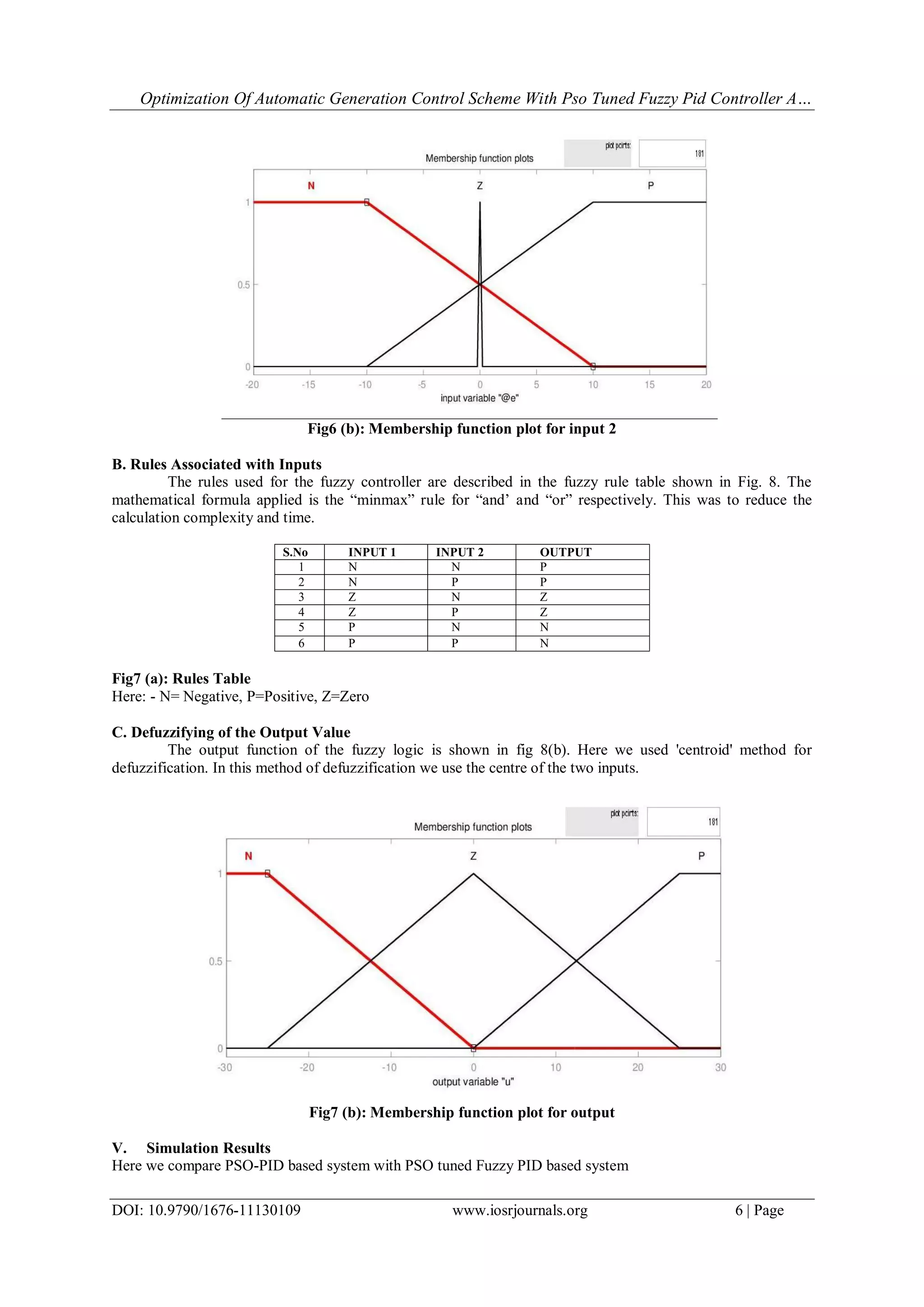
Iv. Fuzzy Logic Working
The working of the Fuzzy Logic controller can be divided into three parts namely; allocation of the
area inputs, rules associated with the inputs & defuzzifying of the output.
A. Allocation of the Area inputs
Here frequency deviation and error are the two inputs for the fuzzy logic controller. Both the frequency
deviation and error were divided into three control areas based on magnitude and sign. These are Negative (N),
zero (Z), Positive (P) .Here fig 6(a) & 6(b) represents the input functions for the fuzzy logic controller.
Fig6 (a): Membership function plot for input 1](https://image.slidesharecdn.com/a011130109-160706061422/75/A011130109-5-2048.jpg)
![Optimization Of Automatic Generation Control Scheme With Pso Tuned Fuzzy Pid Controller A…
DOI: 10.9790/1676-11130109 www.iosrjournals.org 8 | Page
Fig10: Tie line deviation response of a PSO based Test system
Fuzzy Logic Based Test system:
Tie line deviation of a PSO tuned Fuzzy PID based test system is shown below:
Fig11: Tie-line deviation for a PSO tuned Fuzzy PID based test system
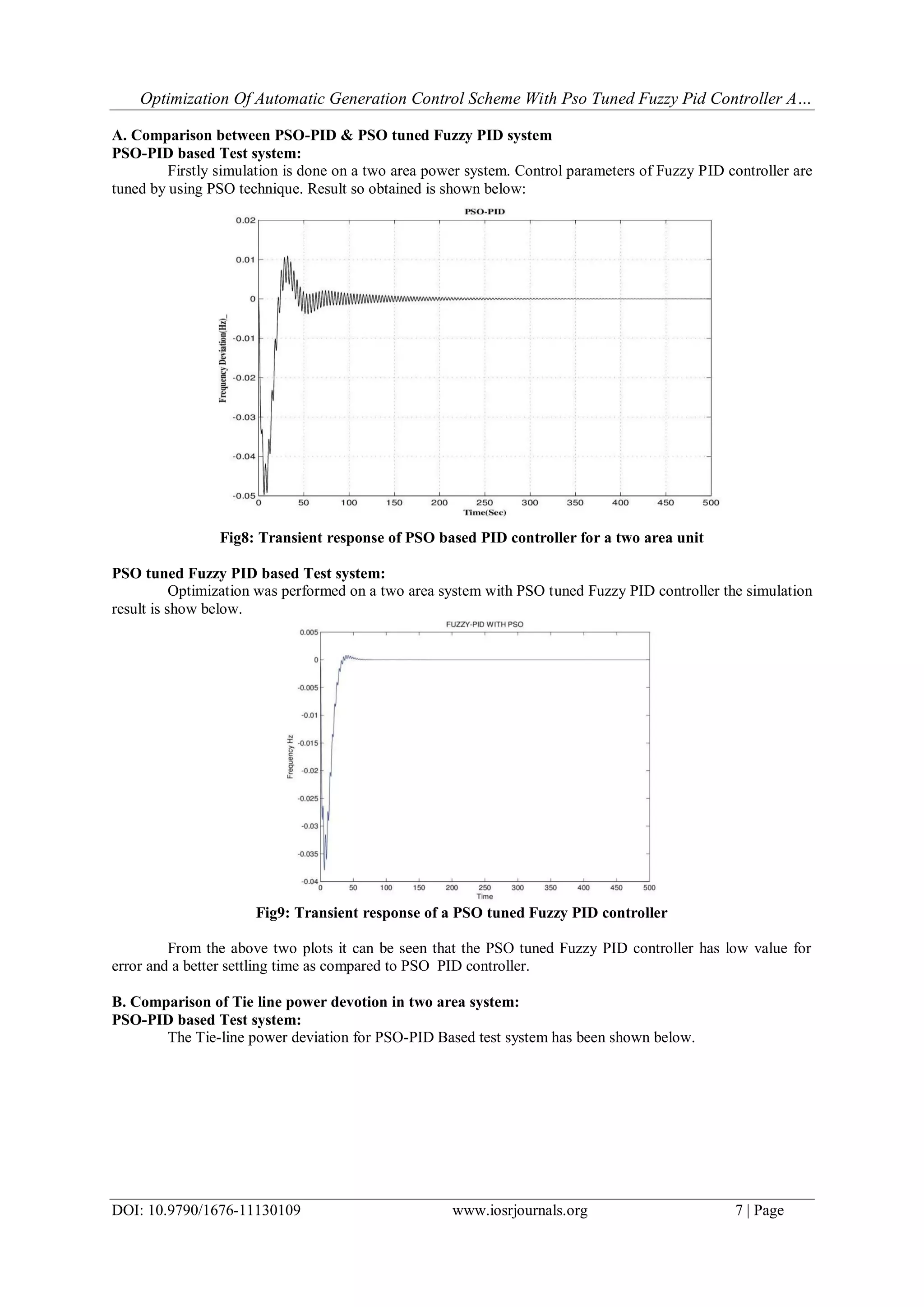
From Fig 10 & 11 it can be seen that the settling time for the Tie line deviation for PSO tuned Fuzzy
PID based test system is much better as compared to PSO-PID based test system.
III. Conclusion
Significant conclusion of this paper is as follows:
(a)This paper presents design method for determining the Fuzzy PID controller parameters using the PSO
Algorithm.
(b) A comparative study is made between PSO based PID controller and PSO tuned Fuzzy PID based PID
controller. The results show that the proposed approach had superior features, including easy execution, stable
convergence characteristic, and good computational efficiency. Fast tuning of optimum PID controller
parameters yields high-quality solution.
(c) Compared with the PSO-PID, the proposed method was indeed more efficient and robust in improving the
step response of an AGC system.
(d)PSO tuned Fuzzy PID based optimization technique have yielded good results.
Reference
Journal Papers:
[1] HasanBevrani&TakashiHiyama,japan -Intelligent Automatic Generation Control.Taylor & francis gp publishing co. -2011
[2] Dr.Sandeep Bhongade,prof H.O.Gupta senior member IEEE-Performance of SMES unit on Artificial Neural Network based multi
area AGC scheme.journal of power electronics & power system.Vol-1.March-2011.
[3] Mohd.Hassan Ali senior member IEEE-An overview of SMES application in energy & power system, Vol. No.1-2010.](https://image.slidesharecdn.com/a011130109-160706061422/75/A011130109-8-2048.jpg)
![Optimization Of Automatic Generation Control Scheme With Pso Tuned Fuzzy Pid Controller A…
DOI: 10.9790/1676-11130109 www.iosrjournals.org 9 | Page
[4] Demiroren “Application to self tunning to Automatic Generation Control in power system including SMES unit” ,Newyork.2009
[5] S.P.Ghoshal Dept of Electrical Engg NIT Durgapur-Optimized AGC by SSSC & TCPS in coordination with SMES for two area
HydroHydro power system.International Conference on advances incomputing,Control&telecommunicationtechnologie.2009
[6] James Blondin-Particle Swarm Optimization:A tutorial –sept 9 2009.
[7] FransVan derbergh-Analysis of particle swarm optimizers,University of Pretoria etd-2006
[8] Micheal N. Varhatis-On the computation of all global minimizers in Particle Swarm Optimization ,Vol 8,No.3 –2004.
[9] James Kennedy and Russell Eberhart,-Particle swarm optimization,In Proceedings of the IEEE International Conference on Neural
Networks, volume IV, pages 1942–1948, Piscataway, NJ, 1995.
[10] Yuhui Shi and Russell Eberhart, “A modified particle swarm optimizer”, Proceedings of the IEEE International Conference on
Evolutionary Computation, pages 69–73, 1998.
[11] J. J. Buckley, “Universal fuzzy controllers,” Auromatica, vol. 28, pp. 1245-1248, 1992.
[12] J. Baldwin and N. Guild, “Modeling controllers using fuzzy relations,” Kybemetes, vol. 9, pp. 223-229, 1980.
Chapters in Books:
[13] P.Kundur, Tata Mcgraw-hill Publishing company limited. a hand book on Power System stability & Control (new Delhi 1994)
page no 601-604
Appendix
Table: The system data (capacity of each area is 1000MW)
s.no INPUT 1 INPUT 2 OUTPUT
1 N N P
2 N P P
3 Z N Z
4 Z P Z
5 P N N
6 P P N
Here: - N= Negative, P=Positive, Z=Zero](https://image.slidesharecdn.com/a011130109-160706061422/75/A011130109-9-2048.jpg)

The document describes optimizing an automatic generation control (AGC) scheme for a two-area power system using a particle swarm optimization (PSO) tuned fuzzy PID controller. A linearized model of the two-area power system is presented. A fuzzy PID controller is used to regulate the area control error of each area. The gains of the fuzzy PID controller are optimized using PSO to minimize time-domain performance metrics. Simulation results show the PSO tuned fuzzy PID controller provides better dynamic response than a conventional PSO PID controller, with lower error and faster settling time. Comparisons of tie-line power deviation also show improved performance with the PSO tuned fuzzy approach. The paper concludes the proposed method efficiently tunes fuzzy PID parameters


![Coded Agents – with UiPath SDK + LangGraph [Virtual Hands-on Workshop]](https://cdn.slidesharecdn.com/ss_thumbnails/codedagentsdeck-251215155422-5497c599-thumbnail.jpg?width=640&height=640&fit=bounds)


![Vibe Coding vs. Spec-Driven Development [Free Meetup]](https://cdn.slidesharecdn.com/ss_thumbnails/vibecodingvsspecdrivendevelopment-251209105622-43f455e7-thumbnail.jpg?width=640&height=640&fit=bounds)

