SlideShare a Scribd company logo
IJRET: International Journal of Research in Engineering and Technology eISSN: 2319-1163 | pISSN: 2321-7308
__________________________________________________________________________________________
IC-RICE Conference Issue | Nov-2013, Available @ http://www.ijret.org 125
A STUDY OF R.C.C. BEAM-COLUMN CONNECTION SUBJECTED TO
MONOTONIC LOADING
S. S. Patil1
, S. S. Manekari2
1, 2
Department of Civil Engineering, Walchand Institute of Technology Seth Walchand Hirachand Marg, Ashok Chowk,
Solapur-413006 ( M.S.) India
sspatil1962@gmail.com, manekariss@rediffmail.com
Abstract
Beam and column where intersects is called as joint or Connection. The different types of joints are classified as corner joint, exterior
joint, interior joint etc. on beam column joint applying quasi-static loading .i. e. monotonic loading on cantilever end of the beam and
study of various parameters as to be find out on corner and exterior beam column joint i.e. maximum stress, minimum stress,
displacement and variation in stiffness of beam column joint can be analyzed in Ansys software ( Non-Linear FEM Software) The
various research studies focused on corner and exterior beam column joints and their behavior, support conditions of beam-column
joints. Some recent experimental studies, however, addressed beam-column joints of substandard RC frames with weak columns, poor
anchorage of longitudinal beam bars and insufficient transverse reinforcement. the behavior of exterior beam column joint is different
than the corner beam column joint.
Keywords: beam, column, corner, exterior, joint, monotonic load, quasi-static, varying stiffness.
--------------------------------------------------------------------***-------------------------------------------------------------------------
1. INTRODUCTION
Earthquakes are one of the most feared natural phenomena
that are relatively unexpected and whose impact is sudden due
to the almost instantaneous destruction that a major
earthquake can produce. Severity of ground shaking at a given
location during an earthquake can be minor, moderate and
strong which relatively speaking occur frequently,
occasionally an rarely respectively. Design and construction of
a building to resist the rare earthquake shaking that may come
only once in 500 years or even once in 2000 years at a chosen
project site even though life of the building itself may be only
50 to 100 years is too robust and also too expensive. Hence,
the main intention is to make building earthquake-resistant
that resist the effect of ground shaking although it may get
damaged severely but would not collapse during even the
strong earthquake. Thus, the safety of people and contents is
assured in earthquake-resistant buildings. This is a major
objective of seismic design codes throughout the world.
A Beam-Column Joints is defined as the portion of a column
within the depth of the beams that frame into it. Formerly, the
design of monolithic joints was limited to providing adequate
encourage for the reinforcement. However the increasing use
of high strength concrete, resulting in smaller member cross
section, and the use large diameter of reinforcing bars now
required that more attention be given to joint design and
detailing.
1.1 Exterior Joint Mechanism
When the joint is applied with different loads the mechanism
of force transfer takes place. This mechanism is shown in
fig.1.
Fig1. Joint loads acting on the free body of a typical joint of a
frame Subjected to gravity loads.(Exterior Seismic Beam
Column Joint)
2. LITERATURE REVIEW
Vladmir Guilherne Haach, Ana Lucia Home De Cresce El
Debs, Mounir Khalil El Debs
This paper investigates the influence of the column axial load
on the joint shear strength through numerical simulations. The
numerical study is performed through the software ABAQUS,
IJRET: International Journal of Research in Engineering and Technology eISSN: 2319-1163 | pISSN: 2321-7308
__________________________________________________________________________________________
IC-RICE Conference Issue | Nov-2013, Available @ http://www.ijret.org 126
based on Finite Element Method. A comparison of the
numerical and experimental results is presented in order to
validate the simulation. The results showed that the column
axial load made the joint more stiff but also introduced
stresses in the beam longitudinal reinforcement. A more
uniform stress distribution in the joint region is obtained when
the stirrup ratio is increased. Furthermore, some tension from
the top beam longitudinal reinforcement is absorbed by the
stirrups located at the upper part of the joint. This paper gives
the affect of stirrup ratio to exterior beam-column joints where
the beam is loaded monotonically. It was concluded that
stirrups located in the upper region of the joint absorb part of
the tension stress proceeding from beam longitudinal
reinforcement and improve their anchorage.
Hegger Josef,Sherif Alaa and Roeser Wolfgang This paper
investigate the behavior of exterior and interior beam-column
joints by Nonlinear finite element analysis using ATENA a
software for nonlinear analysis of reinforced concrete
structures. The model has been calibrated using the results of
the third author’s tests. The behavior of exterior and interior
beam-column turned out to be different .The parameters
influencing the shear strength are not the same for both types
of connections. Different parameters like effect of the material
properties, effect of geometry of connection, effect of
reinforcement, effect of concrete compressive strength and
joint slenderness. The parameters influencing the shear
capacity are different for exterior and interior connections.
The FE results were compared with the author’s experimental
results and the good agreement between the two was achieved.
3. FRAMED JOINTS
Beam column joints can be critical regions in reinforced
concrete frames designed for inelastic response to severe
seismic attack. As a consequence of seismic moments in
columns of opposite signs immediately above and below the
joint, the joint region is subjected to horizontal and vertical
shear forces whose magnitude is typically many times higher
than in the adjacent beams and columns.
Features of joint behavior: Under seismic action large shear
forces may be introduced into beam–column joints
irrespective of whether plastic hinges develop at column faces
or at some other section of beams. These shear forces may
cause a failure in the joint core due to the breakdown of shear
or bond mechanisms or both.
Equilibrium criteria: As a joint is also a part of a column,
examination of its function as a column component is
instructive. An interior column extending between points of
contra flexure, at half storey heights may be isolated as free
body, as shown in fig. Actions introduced by symmetrically
reinforced beams to the column are shown in fig. to be internal
horizontal tension Tb and compression Cb forces and vertical
beam shear Vb forces.
(a) (b) (c) (d) (e)
Fig.2. Features of column and joint behavior
Making approximation that Cb = Tb and the beam shear on
both sides of the joint are equal, equilibrium of the free body
shown requires a horizontal column shear force of
The intensity of the horizontal shear within the joint Vjh is
typically four to six times larger than that across the column
between adjacent joints Vc.
c
cbbb
c
l
hVZT
V
+
=
2
IJRET: International Journal of Research in Engineering and Technology eISSN: 2319-1163 | pISSN: 2321-7308
__________________________________________________________________________________________
IC-RICE Conference Issue | Nov-2013, Available @ http://www.ijret.org 127
Fig3 Typical Beam Column Connections
4. LOADING SYSTEMS
4.1 Types of Loading systems
The behavior of building is studied with different types of
loads.
1) Static loading
Static means slow loading in structural testing.
-Test of components
-Beams (bending), column (axial), beams and columns
Purpose of testing
-Determine strength limits
-Determine the flexibility/rigidity of structures
2) Quasi-static loading
Very slowly applied loading in one direction (monotonic)
3) Quasi-static reversed cyclic loading
Very slowly applied loading in both direction (cyclic)
4) Dynamic (random) loading
-Shake at the base or any other elevation of the structure
-Shaking similar to that during earthquakes.
5. FINITE ELEMENT ANALYSIS
The Finite Element Analysis is a numerical technique in which
all complexities of the problems varying shape, boundary
conditions and loads are maintained as they are but the
solutions obtained are approximate. Solutions can be obtained
for all problems by Finite Element Analysis.
Various steps involved in FEM are as follows.
1. Selection of field variables and the elements.
2. Discretization of structure.
3. Finding the element properties
4. Assembling element stiffness matrix
5. Solution of nodal unknowns
6. ELEMENT TYPE USED
Reinforced Concrete: An eight-node solid element, Solid65,
was used to model the concrete. The solid element has eight
nodes with three degrees of freedom at each node –
translations in the nodal x, y, and z directions. The element is
capable of plastic deformation, cracking in three orthogonal
directions, and crushing. The geometry and node locations for
this element type are shown in below.
Fig4. Solid65 – 3-D reinforced concrete solid (ANSYS 1998)
A Link8 element is used to model the steel reinforcement.
Two nodes are required for this element. Each node has three
degrees of freedom, – translations in the nodal x, y, and z
directions. The element is also capable of plastic deformation.
7. MATERIAL PROPERTIES
Concrete Development of a model for the behavior of
concrete is a challenging task. Concrete is a quasi-brittle
material and has different behavior in compression and
tension. The tensile strength of concrete is typically 8-15% of
the compressive strength (Shah, et al. 1995). Figure below
shows a typical stress-strain curve for normal weight concrete
(Bangash 1989).In compression, the stress-strain curve for
concrete is linearly elastic up to about 30 percent of the
maximum compressive strength. Above this point, the stress
increases gradually up to the maximum compressive strength.
After it reaches the maximum compressive strength σcu
, the
curve descends into a softening region, and eventually
crushing failure occurs at an ultimate strain εcu
. In tension, the
stress-strain curve for concrete is approximately linearly
elastic up to the maximum tensile strength. After this point,
the concrete cracks and the strength decreases gradually to
zero (Bangash 1989).
7.1 Steel Reinforced Concrete [Smeared Model]
Material Properties
In this project the structure has been modeled using Steel
Reinforced Concrete. The material properties mentioned
below act equivalent for a Smeared Reinforcement concrete
model using solid 65 element in Ansys. Many research papers
have been published using similar kind of model. Broujerdian
et. al (2010) have worked using a similar approach. The used
of this features enables obtaining good results with less solver
and modeling time.
8. PROBLEM STATEMENT
8.1 Problem Definition
A ground plus five Storey RC office building is considered.
Plan dimensions :12 m x 12 m
IJRET: International Journal of Research in Engineering and Technology eISSN: 2319-1163 | pISSN: 2321-7308
__________________________________________________________________________________________
IC-RICE Conference Issue | Nov-2013, Available @ http://www.ijret.org 128
Location considered : Zone-III
Soil Type considered :Rock Soil
8.2 General Data of Building:
• Grade of concrete : M 20
• Grade of steel considered : Fe 250, Fe 415
• Live load on roof : 2 KN/m2
(Nil
for earthquake)
• Live load on floors : 4 KN/m2
(50
% for earthquake)
• Roof finish : 1.0 KN/m2
• Floor finish : 1.0 KN/m2
• Brick wall in longitudinal direction (BL) : 250
mm thick
• Brick wall in transverse direction (BT) : 150 mm thick
• Beam in longitudinal direction : 230X300 mm
• Beam in transverse direction : 230X300 mm
• Column size : 300X600 mm
• Density of concrete : 25 KN/m3
• Density of brick wall including plaster : 20 KN/m3
• Plinth beam(PB1) : 350X250 mm
• Plinth beam(PB2) : 250X300 mm
8.3 Parametric Study
The exterior and corner beam-column joints are studied with
different parameters like i.e. Maximum principle stress,
Minimum principle stress, Displacement, Deformation also
studied end conditions of beam column joint i.e. fixed end
conditions, Hinge end conditions and Stiffness variation of
beam column joint i.e. Corner and Exterior joints.
9. FINITE ELEMENT MODELLING AND
ANALYSISOF BEAM-COLUMN JOINTS
The exterior and corner beam-column joint is considered to
study joint behavior subjected to monotonic loading.
Preparation of FE model is carried out based on results
obtained from space frame analysis of a building located in
zone-III. Model construction is done by defining geometrical
joints and lines. Material definition is carried out prior to
assigning of macro elements. The joint is fully restrained at
the column ends. The load is applied at the tip of the beam in
one direction.
Fig5. Modeling of corner beam column joints in the Ansys
Fig.6..Modeling of Exterior beam column joints in the Ansys
IJRET: International Journal of Research in Engineering and Technology eISSN: 2319-1163 | pISSN: 2321-7308
__________________________________________________________________________________________
IC-RICE Conference Issue | Nov-2013, Available @ http://www.ijret.org 129
9. RESULTS AND DISCUSSIONS
9.1 Variation in stiffness of Corner beam column
joint (For Displacement)
Table 1
Fig.7 LOAD VS MAXIMUM DEFORMATION
9.2 Variation in stiffness of corner beam column joint
(Minimum Stress)
Table 2
Fig.8.LOAD VS MINIMUM STRESS
9.3 Variation in stiffness of corner beam column joint
(Maximum Stress)
Table 3
Fig.9. LOAD VS MAXIMUM STRESS GRAPH
Load
in
KN
Displa
cement
in mm
Displaceme
nt in mm
Displace
ment in
mm
Displacement
in mm
Sj=0.1
8
Sj=1.29 Sj=2.05 Sj=0.75
5 0.4172 0.34116 0.274849 0.5875
10 0.8344 0.68233 0.549698 1.175
15 1.6689 1.36467 1.099396 1.3512
20 3.3478 2.7293 1.319256 1.6215
25 3.6889 3.4095 1.649056 2.0268
30 3.983 4.4295 2.141056 2.6346
Load
in KN
Mini. Stress
in N/mm2
Mini.
Stress in
N/mm2
Mini.
Stress
In N/mm2
Mini.
Stress
In N/mm2
Sj=0.18 Sj=1.29 Sj=2.05 Sj=0.75
5 -0.931495 -0.889535 -0.922823 -0.035402
10 -3.92411 -1.21114 -1.33809 -0.88506
15 -4.00092 -2.12256 -1.53242 -1.77012
20 -6.00393 -2.13257 -1.56506 -2.27215
25 -6.94422 -2.33399 -1.66497 -2.30116
30 -7.60862 -2.34361 -1.8868 -3.2847
Load
in KN
Maxi.
Stress
in N/mm2
Maxi.
Stress
in N/mm2
Maxi.
Stress
in
N/mm2
Maxi.
Stress in
N/mm2
Sj=0.18 Sj=1.29 Sj=2.05 Sj=0.75
5 0.303477 0.3956 0.389974 0.008042
10 2.20581 1.66923 0.585308 0.201056
15 2.22582 1.67924 1.15246 0.402113
20 3.77446 1.96634 1.20463 1.21377
25 4.6321 2.93769 1.29138 1.23761
30 6.17119 6.50058 2.3821 4.01801
IJRET: International Journal of Research in Engineering and Technology eISSN: 2319-1163 | pISSN: 2321-7308
__________________________________________________________________________________________
IC-RICE Conference Issue | Nov-2013, Available @ http://www.ijret.org 130
9.4 Variation in stiffness of Exterior beam column
joint (For Displacement)
Table 4
Fig.10. LOAD VS MAXIMUM DEFORMATION
9.5 Variation in stiffness of Exterior beam column
joint (Minimum Stress)
Table 5
Fig.11. LOAD VS MINIMUM STRESS GRAPH
9.6 Variation in stiffness of Exterior beam column
joint (Maximum Stress)
Table6
Fig12. LOAD VS MAXIMUM STRESS GRAPH
Loa
d in
KN
Displaceme
nt in mm
Displaceme
nt in mm
Displacem
ent in mm
Displace
ment in
mm
Sj=1.29 Sj=2.05 Sj=0.75 Sj=0.18
5 0.604115 0.60052 0.213883 0.507809
10 1.20823 1.20104 0.427767 1.0156
15 2.41646 1.38119 0.641712 1.16794
20 2.8996 1.6571 1.81128 1.40134
25 3.6244 2.0714 2.12017 1.75134
30 3.9248 2.6927 2.60442 2.27664
Load
in
KN
Mini.
Stress in
N/mm2
Mini.
Stress in
N/mm2
Mini.
Stress in
N/mm2
Mini.
Stress in
N/mm2
Sj=1.29 Sj=2.05 Sj=0.75 Sj=0.18
5 -0.858169 -2.09364 -0.429264 -0.88953
10 -1.71634 -3.06832 -0.858527 -2.25308
15 -2.33399 -4.05034 -1.397001 -2.68991
20 -2.60959 -4.899265 -1.57095 -2.88285
25 -2.97925 -5.79853 -2.13031 -3.91109
30 -5.54457 -6.09465 -2.83467 -4.5792
Load
in
KN
Maxi.
Stress in
N/mm2
Maxi.
Stress in
N/mm2
Maxi.
Stress
in
N/mm2
Maxi.
Stress
in
N/mm2
Sj=1.29 Sj=2.05 Sj=0.75 Sj=0.18
5 1.5166 0.67842 1.3244 2.18446
10 3.0332 3.00113 2.64879 3.8436
15 4.543 3.2643 3.55204 4.4024
20 6.5429 3.50445 7.08526 6.82696
25 8.0439 4.00889 8.40464 7.9676
30 10.0439 4.678425 9.2199 9.9624
IJRET: International Journal of Research in Engineering and Technology eISSN: 2319-1163 | pISSN: 2321-7308
__________________________________________________________________________________________
IC-RICE Conference Issue | Nov-2013, Available @ http://www.ijret.org 131
CONCLUSIONS
1) As load increases displacement, minimum stress and
maximum stress also increases.
2) For stiffness variation of corner joint for Sj=0.18 the
displacement is minimum as compare to Sj=1.29,
Sj=2.05, Sj=0.75.
3) For stiffness variation of corner joint for Sj=0.18 the
minimum stress is more as compare to Sj=1.29 and
Sj=2.05,for Sj=0.75 the minimum stress is maximum as
compare to Sj=0.18.
4) For stiffness variation of corner joint for Sj=0.18 the
maximum stress is more as compare to Sj=1.29 and
Sj=2.05,for Sj=0.75 the maximum stress is maximum as
compare to Sj=0.18.
5) For stiffness variation of Exterior joint for Sj=1.29 the
displacement is minimum as compare to Sj=2.05,for
Sj=0.75 and for Sj=0.18 the displacement is maximum as
compare to Sj=1.29.
6) For stiffness variation of Exterior joint for Sj=1.29 the
minimum stress is more as compare to Sj=2.05 and
Sj=0.75,for Sj=0.18 the minimum stress is more as
compare to Sj=1.29.
7) For stiffness variation of Exterior joint for Sj=1.29 the
maximum stress is less as compare to Sj=2.05.for
remaining stiffness Sj=0.75 and Sj=0.18 the maximum
stress is less. ( minimum )
8) As stiffness of the structure changes the displacement,
minimum stress and maximum stress changes Non-
linearly.
9) The behavior of corner beam column joint is different
than that of the exterior beam column joint.
Where Sj=Joint Stiffness factor i.e. Stiffness of Beam /
Stiffness of Column Ratio
REFERENCES
[1]. Murty.C.V.R, Rai.C.Durgesh, Bajpai.K.K and Jain.S.K
(April 2001) “Anchorage detail and joint design in seismic RC
Frames.”The Indian Concrete Journal pp 274-280.
[2]. Pampanin.S., Calvi.G.M. and Morati.M.(1998) “Seismic
Behavior of Reinforced Concrete Beam-Column Joints
designed for Gravity Loads” 12th European Conference on
Earthquake Engineering pp 1-10.
[3]. R. Vollum* and D. Parker (2008) “External beam-column
joints design to Eurocode2” Magazine of Concrete Research
pp 511-521.
[4]. Shamim Mohammad and Kumar. V (1999) “Behavior of
reinforced concrete Beam column joints-A review “Journal of
Structural Engineering Vol.26, No.3, Pp.207-214.
[5]. Shin.S.W., Lee.S.K. AND Ghosh.S.K.(1992) “High
Strength concrete beam-Column joints” Proceedings of the
Tenth World Conference on Earthquake Engineering pp 3145-
3149.
[6]. Uma. S. R and Meher Prasad. A “Seismic Behavior of
Beam Column Joints in Reinforced Concrete Moment
Resisting Frames”Document No.: IITK-GSDMA-EQ31-V1.0,
Final Report: A - Earthquake Codes, IITK-GSDMA Project on
Building Codes.
[7]. Vladimir Guilherma Haach, Ana Lucia Home De Cresce
El Debs and Mounir Khalil El Debs (2008) “Evaluation of the
influence of the column axial load on the behavior of
monotonically loaded R/C exterior beam-column joints
through Numerical simulations “Engineering Structures pp
965-975.
BIOGRAPHIES:
Prof. Patil S.S, B.E. (Civil), M.E. (Civil -
Structures) ,PhD**
Mr. Manekari S.S.B.E. (Civil), M.E. (Civil -
Structures),L.M.( ISSE)

More Related Content

What's hot

Modeling and Analysis of Retrofitted Exterior RC Beam Column Joint
 Modeling and Analysis of Retrofitted Exterior RC Beam Column Joint Modeling and Analysis of Retrofitted Exterior RC Beam Column Joint
Modeling and Analysis of Retrofitted Exterior RC Beam Column Joint
maged salama
 
How do columns in rc buildings resist
How do columns in rc buildings resistHow do columns in rc buildings resist
How do columns in rc buildings resist
rk pandey
 

What's hot (20)

Seismic behavior of beam column Joint
Seismic behavior of beam column JointSeismic behavior of beam column Joint
Seismic behavior of beam column Joint
 
Modeling and Analysis of Retrofitted Exterior RC Beam Column Joint
 Modeling and Analysis of Retrofitted Exterior RC Beam Column Joint Modeling and Analysis of Retrofitted Exterior RC Beam Column Joint
Modeling and Analysis of Retrofitted Exterior RC Beam Column Joint
 
seismic behaviour of beam column joint
seismic behaviour of beam column jointseismic behaviour of beam column joint
seismic behaviour of beam column joint
 
How do columns in rc buildings resist
How do columns in rc buildings resistHow do columns in rc buildings resist
How do columns in rc buildings resist
 
STUDY ON INFLUENCE OF RIB CONFIGURATION ON BOND STRENGTH DEVELOPMENT BETWEEN ...
STUDY ON INFLUENCE OF RIB CONFIGURATION ON BOND STRENGTH DEVELOPMENT BETWEEN ...STUDY ON INFLUENCE OF RIB CONFIGURATION ON BOND STRENGTH DEVELOPMENT BETWEEN ...
STUDY ON INFLUENCE OF RIB CONFIGURATION ON BOND STRENGTH DEVELOPMENT BETWEEN ...
 
STUDY ON BOND MECHANISM OF PSWC BARS WITH CONCRETE
STUDY ON BOND MECHANISM OF PSWC BARS WITH CONCRETESTUDY ON BOND MECHANISM OF PSWC BARS WITH CONCRETE
STUDY ON BOND MECHANISM OF PSWC BARS WITH CONCRETE
 
BRACED STEEL FRAMES IN EARTHQUAKE
BRACED STEEL FRAMES IN EARTHQUAKEBRACED STEEL FRAMES IN EARTHQUAKE
BRACED STEEL FRAMES IN EARTHQUAKE
 
Reinforced column design
Reinforced column design Reinforced column design
Reinforced column design
 
Retrofitting of RC Beam Column Joint
Retrofitting of RC Beam Column JointRetrofitting of RC Beam Column Joint
Retrofitting of RC Beam Column Joint
 
Lec03 Earthquake Force Using Response Specturum Method (1) (Earthquake Engine...
Lec03 Earthquake Force Using Response Specturum Method (1) (Earthquake Engine...Lec03 Earthquake Force Using Response Specturum Method (1) (Earthquake Engine...
Lec03 Earthquake Force Using Response Specturum Method (1) (Earthquake Engine...
 
Beam column connections
Beam column connectionsBeam column connections
Beam column connections
 
Beams and columns
Beams and columns Beams and columns
Beams and columns
 
Strengthening of RC Arches
Strengthening of RC ArchesStrengthening of RC Arches
Strengthening of RC Arches
 
Earthquake Resistant Masonry Buildings
Earthquake Resistant Masonry Buildings Earthquake Resistant Masonry Buildings
Earthquake Resistant Masonry Buildings
 
Mechanism of load transfored...PRC-I
Mechanism of load transfored...PRC-IMechanism of load transfored...PRC-I
Mechanism of load transfored...PRC-I
 
PPT ON DESIGN OF COLUMN BRACES
PPT ON DESIGN OF COLUMN BRACESPPT ON DESIGN OF COLUMN BRACES
PPT ON DESIGN OF COLUMN BRACES
 
Ductile reinforced concrete beam-column joints with alternative detailing
Ductile reinforced concrete beam-column joints with alternative detailingDuctile reinforced concrete beam-column joints with alternative detailing
Ductile reinforced concrete beam-column joints with alternative detailing
 
Design and analysis of cantilever beam
Design and analysis of cantilever beamDesign and analysis of cantilever beam
Design and analysis of cantilever beam
 
Earthquake tip no.22
Earthquake tip no.22Earthquake tip no.22
Earthquake tip no.22
 
Beam and its types
Beam and its typesBeam and its types
Beam and its types
 

Similar to A study of r.c.c. beam column connection subjected to monotonic loading

Behavior of plan irregularites using composite members by varying column spac...
Behavior of plan irregularites using composite members by varying column spac...Behavior of plan irregularites using composite members by varying column spac...
Behavior of plan irregularites using composite members by varying column spac...
eSAT Journals
 
Behavior of plan irregularites using composite members by varying column spac...
Behavior of plan irregularites using composite members by varying column spac...Behavior of plan irregularites using composite members by varying column spac...
Behavior of plan irregularites using composite members by varying column spac...
eSAT Journals
 
Study of Eccentrically Braced Outrigger Frame under Seismic Exitation
Study of Eccentrically Braced Outrigger Frame under Seismic ExitationStudy of Eccentrically Braced Outrigger Frame under Seismic Exitation
Study of Eccentrically Braced Outrigger Frame under Seismic Exitation
IJTET Journal
 
Study of castellated beam using stiffeners a review
Study of castellated beam using stiffeners a reviewStudy of castellated beam using stiffeners a review
Study of castellated beam using stiffeners a review
eSAT Journals
 
Evaluation of the use of concentric steel bracing to improve seismic performa...
Evaluation of the use of concentric steel bracing to improve seismic performa...Evaluation of the use of concentric steel bracing to improve seismic performa...
Evaluation of the use of concentric steel bracing to improve seismic performa...
eSAT Journals
 

Similar to A study of r.c.c. beam column connection subjected to monotonic loading (20)

IRJET- Effect of Relative Stiffness of Beam-Column Joint on Internal Forces i...
IRJET- Effect of Relative Stiffness of Beam-Column Joint on Internal Forces i...IRJET- Effect of Relative Stiffness of Beam-Column Joint on Internal Forces i...
IRJET- Effect of Relative Stiffness of Beam-Column Joint on Internal Forces i...
 
Effect of modulus of masonry on initial lateral stiffness of infilled frames ...
Effect of modulus of masonry on initial lateral stiffness of infilled frames ...Effect of modulus of masonry on initial lateral stiffness of infilled frames ...
Effect of modulus of masonry on initial lateral stiffness of infilled frames ...
 
Ultimate strength of composite beam with web openings subjected to combined n...
Ultimate strength of composite beam with web openings subjected to combined n...Ultimate strength of composite beam with web openings subjected to combined n...
Ultimate strength of composite beam with web openings subjected to combined n...
 
Behavior of plan irregularites using composite members by varying column spac...
Behavior of plan irregularites using composite members by varying column spac...Behavior of plan irregularites using composite members by varying column spac...
Behavior of plan irregularites using composite members by varying column spac...
 
Behavior of plan irregularites using composite members by varying column spac...
Behavior of plan irregularites using composite members by varying column spac...Behavior of plan irregularites using composite members by varying column spac...
Behavior of plan irregularites using composite members by varying column spac...
 
Seismic performance of friction pendulum bearing by considering storey drift ...
Seismic performance of friction pendulum bearing by considering storey drift ...Seismic performance of friction pendulum bearing by considering storey drift ...
Seismic performance of friction pendulum bearing by considering storey drift ...
 
seismic response of multi storey building equipped with steel bracing
 seismic response of multi storey building equipped with steel bracing seismic response of multi storey building equipped with steel bracing
seismic response of multi storey building equipped with steel bracing
 
Study of Eccentrically Braced Outrigger Frame under Seismic Exitation
Study of Eccentrically Braced Outrigger Frame under Seismic ExitationStudy of Eccentrically Braced Outrigger Frame under Seismic Exitation
Study of Eccentrically Braced Outrigger Frame under Seismic Exitation
 
Earthquake analysis on 2 d rc frames with different aspect ratios of masonry ...
Earthquake analysis on 2 d rc frames with different aspect ratios of masonry ...Earthquake analysis on 2 d rc frames with different aspect ratios of masonry ...
Earthquake analysis on 2 d rc frames with different aspect ratios of masonry ...
 
Earthquake analysis on 2 d rc frames with different
Earthquake analysis on 2 d rc frames with differentEarthquake analysis on 2 d rc frames with different
Earthquake analysis on 2 d rc frames with different
 
Earthquake analysis on 2 d rc frames with different aspect ratios of masonry ...
Earthquake analysis on 2 d rc frames with different aspect ratios of masonry ...Earthquake analysis on 2 d rc frames with different aspect ratios of masonry ...
Earthquake analysis on 2 d rc frames with different aspect ratios of masonry ...
 
Analysis of Beam-Column Joint subjected to Seismic Lateral Loading – A Review
Analysis of Beam-Column Joint subjected to Seismic Lateral Loading – A ReviewAnalysis of Beam-Column Joint subjected to Seismic Lateral Loading – A Review
Analysis of Beam-Column Joint subjected to Seismic Lateral Loading – A Review
 
Study of castellated beam using stiffeners a review
Study of castellated beam using stiffeners a reviewStudy of castellated beam using stiffeners a review
Study of castellated beam using stiffeners a review
 
Effect of steel bracing on vertically irregular r.c.c building frames under s...
Effect of steel bracing on vertically irregular r.c.c building frames under s...Effect of steel bracing on vertically irregular r.c.c building frames under s...
Effect of steel bracing on vertically irregular r.c.c building frames under s...
 
Comparative Study on Masonry Infill, Friction Dampers and Bare Frame Structur...
Comparative Study on Masonry Infill, Friction Dampers and Bare Frame Structur...Comparative Study on Masonry Infill, Friction Dampers and Bare Frame Structur...
Comparative Study on Masonry Infill, Friction Dampers and Bare Frame Structur...
 
Dynamic analysis of a reinforced concrete horizontal curved beam using software
Dynamic analysis of a reinforced concrete horizontal curved beam using softwareDynamic analysis of a reinforced concrete horizontal curved beam using software
Dynamic analysis of a reinforced concrete horizontal curved beam using software
 
Experimental studies on confined steel concrete composite beams under pure be...
Experimental studies on confined steel concrete composite beams under pure be...Experimental studies on confined steel concrete composite beams under pure be...
Experimental studies on confined steel concrete composite beams under pure be...
 
Comparison of bracings and shear walls as seismic strengthening methods to bu...
Comparison of bracings and shear walls as seismic strengthening methods to bu...Comparison of bracings and shear walls as seismic strengthening methods to bu...
Comparison of bracings and shear walls as seismic strengthening methods to bu...
 
A04520105
A04520105A04520105
A04520105
 
Evaluation of the use of concentric steel bracing to improve seismic performa...
Evaluation of the use of concentric steel bracing to improve seismic performa...Evaluation of the use of concentric steel bracing to improve seismic performa...
Evaluation of the use of concentric steel bracing to improve seismic performa...
 

More from eSAT Journals

Material management in construction – a case study
Material management in construction – a case studyMaterial management in construction – a case study
Material management in construction – a case study
eSAT Journals
 
Laboratory studies of dense bituminous mixes ii with reclaimed asphalt materials
Laboratory studies of dense bituminous mixes ii with reclaimed asphalt materialsLaboratory studies of dense bituminous mixes ii with reclaimed asphalt materials
Laboratory studies of dense bituminous mixes ii with reclaimed asphalt materials
eSAT Journals
 
Geographical information system (gis) for water resources management
Geographical information system (gis) for water resources managementGeographical information system (gis) for water resources management
Geographical information system (gis) for water resources management
eSAT Journals
 
Estimation of surface runoff in nallur amanikere watershed using scs cn method
Estimation of surface runoff in nallur amanikere watershed using scs cn methodEstimation of surface runoff in nallur amanikere watershed using scs cn method
Estimation of surface runoff in nallur amanikere watershed using scs cn method
eSAT Journals
 
Effect of variation of plastic hinge length on the results of non linear anal...
Effect of variation of plastic hinge length on the results of non linear anal...Effect of variation of plastic hinge length on the results of non linear anal...
Effect of variation of plastic hinge length on the results of non linear anal...
eSAT Journals
 

More from eSAT Journals (20)

Mechanical properties of hybrid fiber reinforced concrete for pavements
Mechanical properties of hybrid fiber reinforced concrete for pavementsMechanical properties of hybrid fiber reinforced concrete for pavements
Mechanical properties of hybrid fiber reinforced concrete for pavements
 
Material management in construction – a case study
Material management in construction – a case studyMaterial management in construction – a case study
Material management in construction – a case study
 
Managing drought short term strategies in semi arid regions a case study
Managing drought    short term strategies in semi arid regions  a case studyManaging drought    short term strategies in semi arid regions  a case study
Managing drought short term strategies in semi arid regions a case study
 
Life cycle cost analysis of overlay for an urban road in bangalore
Life cycle cost analysis of overlay for an urban road in bangaloreLife cycle cost analysis of overlay for an urban road in bangalore
Life cycle cost analysis of overlay for an urban road in bangalore
 
Laboratory studies of dense bituminous mixes ii with reclaimed asphalt materials
Laboratory studies of dense bituminous mixes ii with reclaimed asphalt materialsLaboratory studies of dense bituminous mixes ii with reclaimed asphalt materials
Laboratory studies of dense bituminous mixes ii with reclaimed asphalt materials
 
Laboratory investigation of expansive soil stabilized with natural inorganic ...
Laboratory investigation of expansive soil stabilized with natural inorganic ...Laboratory investigation of expansive soil stabilized with natural inorganic ...
Laboratory investigation of expansive soil stabilized with natural inorganic ...
 
Influence of reinforcement on the behavior of hollow concrete block masonry p...
Influence of reinforcement on the behavior of hollow concrete block masonry p...Influence of reinforcement on the behavior of hollow concrete block masonry p...
Influence of reinforcement on the behavior of hollow concrete block masonry p...
 
Influence of compaction energy on soil stabilized with chemical stabilizer
Influence of compaction energy on soil stabilized with chemical stabilizerInfluence of compaction energy on soil stabilized with chemical stabilizer
Influence of compaction energy on soil stabilized with chemical stabilizer
 
Geographical information system (gis) for water resources management
Geographical information system (gis) for water resources managementGeographical information system (gis) for water resources management
Geographical information system (gis) for water resources management
 
Forest type mapping of bidar forest division, karnataka using geoinformatics ...
Forest type mapping of bidar forest division, karnataka using geoinformatics ...Forest type mapping of bidar forest division, karnataka using geoinformatics ...
Forest type mapping of bidar forest division, karnataka using geoinformatics ...
 
Factors influencing compressive strength of geopolymer concrete
Factors influencing compressive strength of geopolymer concreteFactors influencing compressive strength of geopolymer concrete
Factors influencing compressive strength of geopolymer concrete
 
Experimental investigation on circular hollow steel columns in filled with li...
Experimental investigation on circular hollow steel columns in filled with li...Experimental investigation on circular hollow steel columns in filled with li...
Experimental investigation on circular hollow steel columns in filled with li...
 
Experimental behavior of circular hsscfrc filled steel tubular columns under ...
Experimental behavior of circular hsscfrc filled steel tubular columns under ...Experimental behavior of circular hsscfrc filled steel tubular columns under ...
Experimental behavior of circular hsscfrc filled steel tubular columns under ...
 
Evaluation of punching shear in flat slabs
Evaluation of punching shear in flat slabsEvaluation of punching shear in flat slabs
Evaluation of punching shear in flat slabs
 
Evaluation of performance of intake tower dam for recent earthquake in india
Evaluation of performance of intake tower dam for recent earthquake in indiaEvaluation of performance of intake tower dam for recent earthquake in india
Evaluation of performance of intake tower dam for recent earthquake in india
 
Evaluation of operational efficiency of urban road network using travel time ...
Evaluation of operational efficiency of urban road network using travel time ...Evaluation of operational efficiency of urban road network using travel time ...
Evaluation of operational efficiency of urban road network using travel time ...
 
Estimation of surface runoff in nallur amanikere watershed using scs cn method
Estimation of surface runoff in nallur amanikere watershed using scs cn methodEstimation of surface runoff in nallur amanikere watershed using scs cn method
Estimation of surface runoff in nallur amanikere watershed using scs cn method
 
Estimation of morphometric parameters and runoff using rs & gis techniques
Estimation of morphometric parameters and runoff using rs & gis techniquesEstimation of morphometric parameters and runoff using rs & gis techniques
Estimation of morphometric parameters and runoff using rs & gis techniques
 
Effect of variation of plastic hinge length on the results of non linear anal...
Effect of variation of plastic hinge length on the results of non linear anal...Effect of variation of plastic hinge length on the results of non linear anal...
Effect of variation of plastic hinge length on the results of non linear anal...
 
Effect of use of recycled materials on indirect tensile strength of asphalt c...
Effect of use of recycled materials on indirect tensile strength of asphalt c...Effect of use of recycled materials on indirect tensile strength of asphalt c...
Effect of use of recycled materials on indirect tensile strength of asphalt c...
 

Recently uploaded

RS Khurmi Machine Design Clutch and Brake Exercise Numerical Solutions
RS Khurmi Machine Design Clutch and Brake Exercise Numerical SolutionsRS Khurmi Machine Design Clutch and Brake Exercise Numerical Solutions
RS Khurmi Machine Design Clutch and Brake Exercise Numerical Solutions
Atif Razi
 
Hybrid optimization of pumped hydro system and solar- Engr. Abdul-Azeez.pdf
Hybrid optimization of pumped hydro system and solar- Engr. Abdul-Azeez.pdfHybrid optimization of pumped hydro system and solar- Engr. Abdul-Azeez.pdf
Hybrid optimization of pumped hydro system and solar- Engr. Abdul-Azeez.pdf
fxintegritypublishin
 
Fruit shop management system project report.pdf
Fruit shop management system project report.pdfFruit shop management system project report.pdf
Fruit shop management system project report.pdf
Kamal Acharya
 
Laundry management system project report.pdf
Laundry management system project report.pdfLaundry management system project report.pdf
Laundry management system project report.pdf
Kamal Acharya
 
Automobile Management System Project Report.pdf
Automobile Management System Project Report.pdfAutomobile Management System Project Report.pdf
Automobile Management System Project Report.pdf
Kamal Acharya
 
Antenna efficency lecture course chapter 3.pdf
Antenna  efficency lecture course chapter 3.pdfAntenna  efficency lecture course chapter 3.pdf
Antenna efficency lecture course chapter 3.pdf
AbrahamGadissa
 
LIGA(E)11111111111111111111111111111111111111111.ppt
LIGA(E)11111111111111111111111111111111111111111.pptLIGA(E)11111111111111111111111111111111111111111.ppt
LIGA(E)11111111111111111111111111111111111111111.ppt
ssuser9bd3ba
 

Recently uploaded (20)

Courier management system project report.pdf
Courier management system project report.pdfCourier management system project report.pdf
Courier management system project report.pdf
 
A case study of cinema management system project report..pdf
A case study of cinema management system project report..pdfA case study of cinema management system project report..pdf
A case study of cinema management system project report..pdf
 
RS Khurmi Machine Design Clutch and Brake Exercise Numerical Solutions
RS Khurmi Machine Design Clutch and Brake Exercise Numerical SolutionsRS Khurmi Machine Design Clutch and Brake Exercise Numerical Solutions
RS Khurmi Machine Design Clutch and Brake Exercise Numerical Solutions
 
Hybrid optimization of pumped hydro system and solar- Engr. Abdul-Azeez.pdf
Hybrid optimization of pumped hydro system and solar- Engr. Abdul-Azeez.pdfHybrid optimization of pumped hydro system and solar- Engr. Abdul-Azeez.pdf
Hybrid optimization of pumped hydro system and solar- Engr. Abdul-Azeez.pdf
 
Online resume builder management system project report.pdf
Online resume builder management system project report.pdfOnline resume builder management system project report.pdf
Online resume builder management system project report.pdf
 
fundamentals of drawing and isometric and orthographic projection
fundamentals of drawing and isometric and orthographic projectionfundamentals of drawing and isometric and orthographic projection
fundamentals of drawing and isometric and orthographic projection
 
WATER CRISIS and its solutions-pptx 1234
WATER CRISIS and its solutions-pptx 1234WATER CRISIS and its solutions-pptx 1234
WATER CRISIS and its solutions-pptx 1234
 
Vaccine management system project report documentation..pdf
Vaccine management system project report documentation..pdfVaccine management system project report documentation..pdf
Vaccine management system project report documentation..pdf
 
NO1 Pandit Amil Baba In Bahawalpur, Sargodha, Sialkot, Sheikhupura, Rahim Yar...
NO1 Pandit Amil Baba In Bahawalpur, Sargodha, Sialkot, Sheikhupura, Rahim Yar...NO1 Pandit Amil Baba In Bahawalpur, Sargodha, Sialkot, Sheikhupura, Rahim Yar...
NO1 Pandit Amil Baba In Bahawalpur, Sargodha, Sialkot, Sheikhupura, Rahim Yar...
 
Fruit shop management system project report.pdf
Fruit shop management system project report.pdfFruit shop management system project report.pdf
Fruit shop management system project report.pdf
 
Student information management system project report ii.pdf
Student information management system project report ii.pdfStudent information management system project report ii.pdf
Student information management system project report ii.pdf
 
Laundry management system project report.pdf
Laundry management system project report.pdfLaundry management system project report.pdf
Laundry management system project report.pdf
 
Natalia Rutkowska - BIM School Course in Kraków
Natalia Rutkowska - BIM School Course in KrakówNatalia Rutkowska - BIM School Course in Kraków
Natalia Rutkowska - BIM School Course in Kraków
 
Automobile Management System Project Report.pdf
Automobile Management System Project Report.pdfAutomobile Management System Project Report.pdf
Automobile Management System Project Report.pdf
 
The Benefits and Techniques of Trenchless Pipe Repair.pdf
The Benefits and Techniques of Trenchless Pipe Repair.pdfThe Benefits and Techniques of Trenchless Pipe Repair.pdf
The Benefits and Techniques of Trenchless Pipe Repair.pdf
 
HYDROPOWER - Hydroelectric power generation
HYDROPOWER - Hydroelectric power generationHYDROPOWER - Hydroelectric power generation
HYDROPOWER - Hydroelectric power generation
 
Antenna efficency lecture course chapter 3.pdf
Antenna  efficency lecture course chapter 3.pdfAntenna  efficency lecture course chapter 3.pdf
Antenna efficency lecture course chapter 3.pdf
 
LIGA(E)11111111111111111111111111111111111111111.ppt
LIGA(E)11111111111111111111111111111111111111111.pptLIGA(E)11111111111111111111111111111111111111111.ppt
LIGA(E)11111111111111111111111111111111111111111.ppt
 
Top 13 Famous Civil Engineering Scientist
Top 13 Famous Civil Engineering ScientistTop 13 Famous Civil Engineering Scientist
Top 13 Famous Civil Engineering Scientist
 
Architectural Portfolio Sean Lockwood
Architectural Portfolio Sean LockwoodArchitectural Portfolio Sean Lockwood
Architectural Portfolio Sean Lockwood
 

A study of r.c.c. beam column connection subjected to monotonic loading

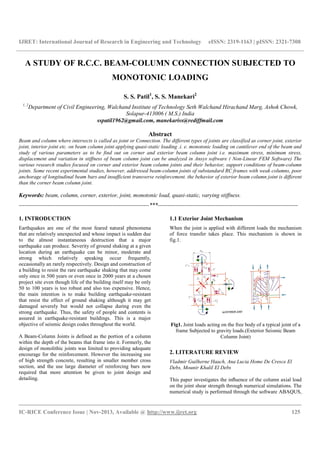
  • 1. IJRET: International Journal of Research in Engineering and Technology eISSN: 2319-1163 | pISSN: 2321-7308 __________________________________________________________________________________________ IC-RICE Conference Issue | Nov-2013, Available @ http://www.ijret.org 125 A STUDY OF R.C.C. BEAM-COLUMN CONNECTION SUBJECTED TO MONOTONIC LOADING S. S. Patil1 , S. S. Manekari2 1, 2 Department of Civil Engineering, Walchand Institute of Technology Seth Walchand Hirachand Marg, Ashok Chowk, Solapur-413006 ( M.S.) India sspatil1962@gmail.com, manekariss@rediffmail.com Abstract Beam and column where intersects is called as joint or Connection. The different types of joints are classified as corner joint, exterior joint, interior joint etc. on beam column joint applying quasi-static loading .i. e. monotonic loading on cantilever end of the beam and study of various parameters as to be find out on corner and exterior beam column joint i.e. maximum stress, minimum stress, displacement and variation in stiffness of beam column joint can be analyzed in Ansys software ( Non-Linear FEM Software) The various research studies focused on corner and exterior beam column joints and their behavior, support conditions of beam-column joints. Some recent experimental studies, however, addressed beam-column joints of substandard RC frames with weak columns, poor anchorage of longitudinal beam bars and insufficient transverse reinforcement. the behavior of exterior beam column joint is different than the corner beam column joint. Keywords: beam, column, corner, exterior, joint, monotonic load, quasi-static, varying stiffness. --------------------------------------------------------------------***------------------------------------------------------------------------- 1. INTRODUCTION Earthquakes are one of the most feared natural phenomena that are relatively unexpected and whose impact is sudden due to the almost instantaneous destruction that a major earthquake can produce. Severity of ground shaking at a given location during an earthquake can be minor, moderate and strong which relatively speaking occur frequently, occasionally an rarely respectively. Design and construction of a building to resist the rare earthquake shaking that may come only once in 500 years or even once in 2000 years at a chosen project site even though life of the building itself may be only 50 to 100 years is too robust and also too expensive. Hence, the main intention is to make building earthquake-resistant that resist the effect of ground shaking although it may get damaged severely but would not collapse during even the strong earthquake. Thus, the safety of people and contents is assured in earthquake-resistant buildings. This is a major objective of seismic design codes throughout the world. A Beam-Column Joints is defined as the portion of a column within the depth of the beams that frame into it. Formerly, the design of monolithic joints was limited to providing adequate encourage for the reinforcement. However the increasing use of high strength concrete, resulting in smaller member cross section, and the use large diameter of reinforcing bars now required that more attention be given to joint design and detailing. 1.1 Exterior Joint Mechanism When the joint is applied with different loads the mechanism of force transfer takes place. This mechanism is shown in fig.1. Fig1. Joint loads acting on the free body of a typical joint of a frame Subjected to gravity loads.(Exterior Seismic Beam Column Joint) 2. LITERATURE REVIEW Vladmir Guilherne Haach, Ana Lucia Home De Cresce El Debs, Mounir Khalil El Debs This paper investigates the influence of the column axial load on the joint shear strength through numerical simulations. The numerical study is performed through the software ABAQUS,
  • 2. IJRET: International Journal of Research in Engineering and Technology eISSN: 2319-1163 | pISSN: 2321-7308 __________________________________________________________________________________________ IC-RICE Conference Issue | Nov-2013, Available @ http://www.ijret.org 126 based on Finite Element Method. A comparison of the numerical and experimental results is presented in order to validate the simulation. The results showed that the column axial load made the joint more stiff but also introduced stresses in the beam longitudinal reinforcement. A more uniform stress distribution in the joint region is obtained when the stirrup ratio is increased. Furthermore, some tension from the top beam longitudinal reinforcement is absorbed by the stirrups located at the upper part of the joint. This paper gives the affect of stirrup ratio to exterior beam-column joints where the beam is loaded monotonically. It was concluded that stirrups located in the upper region of the joint absorb part of the tension stress proceeding from beam longitudinal reinforcement and improve their anchorage. Hegger Josef,Sherif Alaa and Roeser Wolfgang This paper investigate the behavior of exterior and interior beam-column joints by Nonlinear finite element analysis using ATENA a software for nonlinear analysis of reinforced concrete structures. The model has been calibrated using the results of the third author’s tests. The behavior of exterior and interior beam-column turned out to be different .The parameters influencing the shear strength are not the same for both types of connections. Different parameters like effect of the material properties, effect of geometry of connection, effect of reinforcement, effect of concrete compressive strength and joint slenderness. The parameters influencing the shear capacity are different for exterior and interior connections. The FE results were compared with the author’s experimental results and the good agreement between the two was achieved. 3. FRAMED JOINTS Beam column joints can be critical regions in reinforced concrete frames designed for inelastic response to severe seismic attack. As a consequence of seismic moments in columns of opposite signs immediately above and below the joint, the joint region is subjected to horizontal and vertical shear forces whose magnitude is typically many times higher than in the adjacent beams and columns. Features of joint behavior: Under seismic action large shear forces may be introduced into beam–column joints irrespective of whether plastic hinges develop at column faces or at some other section of beams. These shear forces may cause a failure in the joint core due to the breakdown of shear or bond mechanisms or both. Equilibrium criteria: As a joint is also a part of a column, examination of its function as a column component is instructive. An interior column extending between points of contra flexure, at half storey heights may be isolated as free body, as shown in fig. Actions introduced by symmetrically reinforced beams to the column are shown in fig. to be internal horizontal tension Tb and compression Cb forces and vertical beam shear Vb forces. (a) (b) (c) (d) (e) Fig.2. Features of column and joint behavior Making approximation that Cb = Tb and the beam shear on both sides of the joint are equal, equilibrium of the free body shown requires a horizontal column shear force of The intensity of the horizontal shear within the joint Vjh is typically four to six times larger than that across the column between adjacent joints Vc. c cbbb c l hVZT V + = 2
  • 3. IJRET: International Journal of Research in Engineering and Technology eISSN: 2319-1163 | pISSN: 2321-7308 __________________________________________________________________________________________ IC-RICE Conference Issue | Nov-2013, Available @ http://www.ijret.org 127 Fig3 Typical Beam Column Connections 4. LOADING SYSTEMS 4.1 Types of Loading systems The behavior of building is studied with different types of loads. 1) Static loading Static means slow loading in structural testing. -Test of components -Beams (bending), column (axial), beams and columns Purpose of testing -Determine strength limits -Determine the flexibility/rigidity of structures 2) Quasi-static loading Very slowly applied loading in one direction (monotonic) 3) Quasi-static reversed cyclic loading Very slowly applied loading in both direction (cyclic) 4) Dynamic (random) loading -Shake at the base or any other elevation of the structure -Shaking similar to that during earthquakes. 5. FINITE ELEMENT ANALYSIS The Finite Element Analysis is a numerical technique in which all complexities of the problems varying shape, boundary conditions and loads are maintained as they are but the solutions obtained are approximate. Solutions can be obtained for all problems by Finite Element Analysis. Various steps involved in FEM are as follows. 1. Selection of field variables and the elements. 2. Discretization of structure. 3. Finding the element properties 4. Assembling element stiffness matrix 5. Solution of nodal unknowns 6. ELEMENT TYPE USED Reinforced Concrete: An eight-node solid element, Solid65, was used to model the concrete. The solid element has eight nodes with three degrees of freedom at each node – translations in the nodal x, y, and z directions. The element is capable of plastic deformation, cracking in three orthogonal directions, and crushing. The geometry and node locations for this element type are shown in below. Fig4. Solid65 – 3-D reinforced concrete solid (ANSYS 1998) A Link8 element is used to model the steel reinforcement. Two nodes are required for this element. Each node has three degrees of freedom, – translations in the nodal x, y, and z directions. The element is also capable of plastic deformation. 7. MATERIAL PROPERTIES Concrete Development of a model for the behavior of concrete is a challenging task. Concrete is a quasi-brittle material and has different behavior in compression and tension. The tensile strength of concrete is typically 8-15% of the compressive strength (Shah, et al. 1995). Figure below shows a typical stress-strain curve for normal weight concrete (Bangash 1989).In compression, the stress-strain curve for concrete is linearly elastic up to about 30 percent of the maximum compressive strength. Above this point, the stress increases gradually up to the maximum compressive strength. After it reaches the maximum compressive strength σcu , the curve descends into a softening region, and eventually crushing failure occurs at an ultimate strain εcu . In tension, the stress-strain curve for concrete is approximately linearly elastic up to the maximum tensile strength. After this point, the concrete cracks and the strength decreases gradually to zero (Bangash 1989). 7.1 Steel Reinforced Concrete [Smeared Model] Material Properties In this project the structure has been modeled using Steel Reinforced Concrete. The material properties mentioned below act equivalent for a Smeared Reinforcement concrete model using solid 65 element in Ansys. Many research papers have been published using similar kind of model. Broujerdian et. al (2010) have worked using a similar approach. The used of this features enables obtaining good results with less solver and modeling time. 8. PROBLEM STATEMENT 8.1 Problem Definition A ground plus five Storey RC office building is considered. Plan dimensions :12 m x 12 m
  • 4. IJRET: International Journal of Research in Engineering and Technology eISSN: 2319-1163 | pISSN: 2321-7308 __________________________________________________________________________________________ IC-RICE Conference Issue | Nov-2013, Available @ http://www.ijret.org 128 Location considered : Zone-III Soil Type considered :Rock Soil 8.2 General Data of Building: • Grade of concrete : M 20 • Grade of steel considered : Fe 250, Fe 415 • Live load on roof : 2 KN/m2 (Nil for earthquake) • Live load on floors : 4 KN/m2 (50 % for earthquake) • Roof finish : 1.0 KN/m2 • Floor finish : 1.0 KN/m2 • Brick wall in longitudinal direction (BL) : 250 mm thick • Brick wall in transverse direction (BT) : 150 mm thick • Beam in longitudinal direction : 230X300 mm • Beam in transverse direction : 230X300 mm • Column size : 300X600 mm • Density of concrete : 25 KN/m3 • Density of brick wall including plaster : 20 KN/m3 • Plinth beam(PB1) : 350X250 mm • Plinth beam(PB2) : 250X300 mm 8.3 Parametric Study The exterior and corner beam-column joints are studied with different parameters like i.e. Maximum principle stress, Minimum principle stress, Displacement, Deformation also studied end conditions of beam column joint i.e. fixed end conditions, Hinge end conditions and Stiffness variation of beam column joint i.e. Corner and Exterior joints. 9. FINITE ELEMENT MODELLING AND ANALYSISOF BEAM-COLUMN JOINTS The exterior and corner beam-column joint is considered to study joint behavior subjected to monotonic loading. Preparation of FE model is carried out based on results obtained from space frame analysis of a building located in zone-III. Model construction is done by defining geometrical joints and lines. Material definition is carried out prior to assigning of macro elements. The joint is fully restrained at the column ends. The load is applied at the tip of the beam in one direction. Fig5. Modeling of corner beam column joints in the Ansys Fig.6..Modeling of Exterior beam column joints in the Ansys
  • 5. IJRET: International Journal of Research in Engineering and Technology eISSN: 2319-1163 | pISSN: 2321-7308 __________________________________________________________________________________________ IC-RICE Conference Issue | Nov-2013, Available @ http://www.ijret.org 129 9. RESULTS AND DISCUSSIONS 9.1 Variation in stiffness of Corner beam column joint (For Displacement) Table 1 Fig.7 LOAD VS MAXIMUM DEFORMATION 9.2 Variation in stiffness of corner beam column joint (Minimum Stress) Table 2 Fig.8.LOAD VS MINIMUM STRESS 9.3 Variation in stiffness of corner beam column joint (Maximum Stress) Table 3 Fig.9. LOAD VS MAXIMUM STRESS GRAPH Load in KN Displa cement in mm Displaceme nt in mm Displace ment in mm Displacement in mm Sj=0.1 8 Sj=1.29 Sj=2.05 Sj=0.75 5 0.4172 0.34116 0.274849 0.5875 10 0.8344 0.68233 0.549698 1.175 15 1.6689 1.36467 1.099396 1.3512 20 3.3478 2.7293 1.319256 1.6215 25 3.6889 3.4095 1.649056 2.0268 30 3.983 4.4295 2.141056 2.6346 Load in KN Mini. Stress in N/mm2 Mini. Stress in N/mm2 Mini. Stress In N/mm2 Mini. Stress In N/mm2 Sj=0.18 Sj=1.29 Sj=2.05 Sj=0.75 5 -0.931495 -0.889535 -0.922823 -0.035402 10 -3.92411 -1.21114 -1.33809 -0.88506 15 -4.00092 -2.12256 -1.53242 -1.77012 20 -6.00393 -2.13257 -1.56506 -2.27215 25 -6.94422 -2.33399 -1.66497 -2.30116 30 -7.60862 -2.34361 -1.8868 -3.2847 Load in KN Maxi. Stress in N/mm2 Maxi. Stress in N/mm2 Maxi. Stress in N/mm2 Maxi. Stress in N/mm2 Sj=0.18 Sj=1.29 Sj=2.05 Sj=0.75 5 0.303477 0.3956 0.389974 0.008042 10 2.20581 1.66923 0.585308 0.201056 15 2.22582 1.67924 1.15246 0.402113 20 3.77446 1.96634 1.20463 1.21377 25 4.6321 2.93769 1.29138 1.23761 30 6.17119 6.50058 2.3821 4.01801
  • 6. IJRET: International Journal of Research in Engineering and Technology eISSN: 2319-1163 | pISSN: 2321-7308 __________________________________________________________________________________________ IC-RICE Conference Issue | Nov-2013, Available @ http://www.ijret.org 130 9.4 Variation in stiffness of Exterior beam column joint (For Displacement) Table 4 Fig.10. LOAD VS MAXIMUM DEFORMATION 9.5 Variation in stiffness of Exterior beam column joint (Minimum Stress) Table 5 Fig.11. LOAD VS MINIMUM STRESS GRAPH 9.6 Variation in stiffness of Exterior beam column joint (Maximum Stress) Table6 Fig12. LOAD VS MAXIMUM STRESS GRAPH Loa d in KN Displaceme nt in mm Displaceme nt in mm Displacem ent in mm Displace ment in mm Sj=1.29 Sj=2.05 Sj=0.75 Sj=0.18 5 0.604115 0.60052 0.213883 0.507809 10 1.20823 1.20104 0.427767 1.0156 15 2.41646 1.38119 0.641712 1.16794 20 2.8996 1.6571 1.81128 1.40134 25 3.6244 2.0714 2.12017 1.75134 30 3.9248 2.6927 2.60442 2.27664 Load in KN Mini. Stress in N/mm2 Mini. Stress in N/mm2 Mini. Stress in N/mm2 Mini. Stress in N/mm2 Sj=1.29 Sj=2.05 Sj=0.75 Sj=0.18 5 -0.858169 -2.09364 -0.429264 -0.88953 10 -1.71634 -3.06832 -0.858527 -2.25308 15 -2.33399 -4.05034 -1.397001 -2.68991 20 -2.60959 -4.899265 -1.57095 -2.88285 25 -2.97925 -5.79853 -2.13031 -3.91109 30 -5.54457 -6.09465 -2.83467 -4.5792 Load in KN Maxi. Stress in N/mm2 Maxi. Stress in N/mm2 Maxi. Stress in N/mm2 Maxi. Stress in N/mm2 Sj=1.29 Sj=2.05 Sj=0.75 Sj=0.18 5 1.5166 0.67842 1.3244 2.18446 10 3.0332 3.00113 2.64879 3.8436 15 4.543 3.2643 3.55204 4.4024 20 6.5429 3.50445 7.08526 6.82696 25 8.0439 4.00889 8.40464 7.9676 30 10.0439 4.678425 9.2199 9.9624
  • 7. IJRET: International Journal of Research in Engineering and Technology eISSN: 2319-1163 | pISSN: 2321-7308 __________________________________________________________________________________________ IC-RICE Conference Issue | Nov-2013, Available @ http://www.ijret.org 131 CONCLUSIONS 1) As load increases displacement, minimum stress and maximum stress also increases. 2) For stiffness variation of corner joint for Sj=0.18 the displacement is minimum as compare to Sj=1.29, Sj=2.05, Sj=0.75. 3) For stiffness variation of corner joint for Sj=0.18 the minimum stress is more as compare to Sj=1.29 and Sj=2.05,for Sj=0.75 the minimum stress is maximum as compare to Sj=0.18. 4) For stiffness variation of corner joint for Sj=0.18 the maximum stress is more as compare to Sj=1.29 and Sj=2.05,for Sj=0.75 the maximum stress is maximum as compare to Sj=0.18. 5) For stiffness variation of Exterior joint for Sj=1.29 the displacement is minimum as compare to Sj=2.05,for Sj=0.75 and for Sj=0.18 the displacement is maximum as compare to Sj=1.29. 6) For stiffness variation of Exterior joint for Sj=1.29 the minimum stress is more as compare to Sj=2.05 and Sj=0.75,for Sj=0.18 the minimum stress is more as compare to Sj=1.29. 7) For stiffness variation of Exterior joint for Sj=1.29 the maximum stress is less as compare to Sj=2.05.for remaining stiffness Sj=0.75 and Sj=0.18 the maximum stress is less. ( minimum ) 8) As stiffness of the structure changes the displacement, minimum stress and maximum stress changes Non- linearly. 9) The behavior of corner beam column joint is different than that of the exterior beam column joint. Where Sj=Joint Stiffness factor i.e. Stiffness of Beam / Stiffness of Column Ratio REFERENCES [1]. Murty.C.V.R, Rai.C.Durgesh, Bajpai.K.K and Jain.S.K (April 2001) “Anchorage detail and joint design in seismic RC Frames.”The Indian Concrete Journal pp 274-280. [2]. Pampanin.S., Calvi.G.M. and Morati.M.(1998) “Seismic Behavior of Reinforced Concrete Beam-Column Joints designed for Gravity Loads” 12th European Conference on Earthquake Engineering pp 1-10. [3]. R. Vollum* and D. Parker (2008) “External beam-column joints design to Eurocode2” Magazine of Concrete Research pp 511-521. [4]. Shamim Mohammad and Kumar. V (1999) “Behavior of reinforced concrete Beam column joints-A review “Journal of Structural Engineering Vol.26, No.3, Pp.207-214. [5]. Shin.S.W., Lee.S.K. AND Ghosh.S.K.(1992) “High Strength concrete beam-Column joints” Proceedings of the Tenth World Conference on Earthquake Engineering pp 3145- 3149. [6]. Uma. S. R and Meher Prasad. A “Seismic Behavior of Beam Column Joints in Reinforced Concrete Moment Resisting Frames”Document No.: IITK-GSDMA-EQ31-V1.0, Final Report: A - Earthquake Codes, IITK-GSDMA Project on Building Codes. [7]. Vladimir Guilherma Haach, Ana Lucia Home De Cresce El Debs and Mounir Khalil El Debs (2008) “Evaluation of the influence of the column axial load on the behavior of monotonically loaded R/C exterior beam-column joints through Numerical simulations “Engineering Structures pp 965-975. BIOGRAPHIES: Prof. Patil S.S, B.E. (Civil), M.E. (Civil - Structures) ,PhD** Mr. Manekari S.S.B.E. (Civil), M.E. (Civil - Structures),L.M.( ISSE)