Downloaded 27 times

![IITK-BMTPC Earthquake Tip 20
How do Beam-Column Joints in RC Buildings Resist Earthquakes? page 2
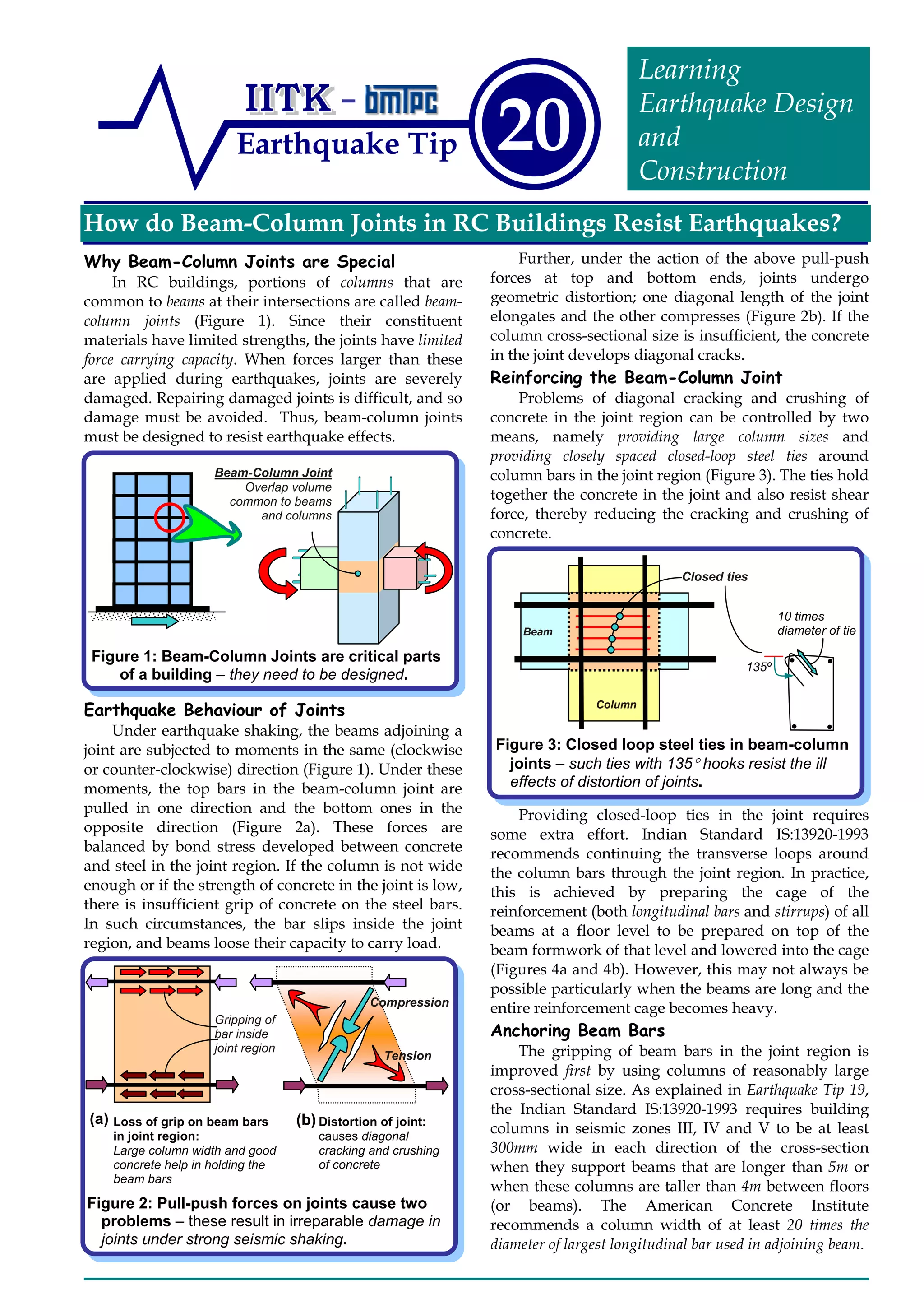
In exterior joints where beams terminate at
columns (Figure 5), longitudinal beam bars need to be
anchored into the column to ensure proper gripping of
bar in joint. The length of anchorage for a bar of grade
Fe415 (characteristic tensile strength of 415MPa) is
about 50 times its diameter. This length is measured
from the face of the column to the end of the bar
anchored in the column. In columns of small widths
and when beam bars are of large diameter (Figure 5a),
a portion of beam top bar is embedded in the column
that is cast up to the soffit of the beam, and a part of it
overhangs. It is difficult to hold such an overhanging
beam top bar in position while casting the column up
to the soffit of the beam. On the other hand, if column
width is large, the beam bars may not extend below
the soffit of the beam (Figure 5b). Thus, it is preferable
to have columns with sufficient width. Such an
approach has been used in the American practice
[ACI318M, 2002].
In interior joints, the beam bars (both top and
bottom) need to go through the joint without any cut
in the joint region. Also, these bars must be placed
within the column bars and with no bends (Figure 6).
Related - Earthquake Tip
Tip17: How do Earthquakes Affect Reinforced Concrete Buildings?
Tip18: How do Beams in RC Buildings Resist Earthquakes?
Tip19: How do Columns in RC Buildings Resist Earthquakes?
Resource Material
ACI 318M, (2002), Building Code Requirements for Structural Concrete
and Commentary, American Concrete Institute, Farmington Hills,
(MI), USA.
IS 13920, (1993), Indian Standard Code of Practice for Ductile Detailing of
Reinforced Concrete Structures Subjected to Seismic Forces, Bureau of
Indian Standards, New Delhi.
SP 123, Design of Beam-Column Joints for Seismic Resistance, Special
Publication, American Concrete Institute, USA, 1991
Next Upcoming Tip
Why are Open-Ground Storey Buildings Dangerous in Earthquakes?
Authored by:
C.V.R.Murty
Indian Institute of Technology Kanpur
Kanpur, India
Sponsored by:
Building Materials and Technology Promotion
Council, New Delhi, India
This release is a property of IIT Kanpur and BMTPC New
Delhi. It may be reproduced without changing its contents
and with due acknowledgement. Suggestions/comments
may be sent to: eqtips@iitk.ac.in. Visit www.nicee.org or
www.bmtpc.org, to see previous IITK-BMTPC Earthquake Tips.
November 2003
Figure 6: Anchorage of beam bars in interior
joints – diagrams (a) and (b) show cross-
sectional views in plan of joint region.
(a) Poor Practice
Beam bars bent in joint region do not
carry tension force unless straightened
Beam bars are within column
bars and also straight
(b) Good Practice
Figure 5: Anchorage of beam bars in exterior
joints – diagrams show elevation of joint region.
(a) (b)
Wide ColumnNarrow Column
ACI 318M-2002
Practice
L-shaped
bar ends
Portion of top beam
bar below soffit of the
beam
Portion of column
already cast
Approximately50timesbardiameter
(c)
Shear failure of RC
beam-column joint
during the 1985
Mexico City
Earthquake,
when beam bars
are passed outside
the column cross-
section
Photofrom:TheEERIAnnotatedSlideCD,
98-2,EERI,Oakland,CA,USA
Beam bars are within column
bars and also straight
Beam
Column
Column
Beam
(a) Stage I :
Beam top bars are not
placed, but horizontal
ties in the joint region
are stacked up.
(c)
Stage III :
Ties in the joint region are
raised to their final locations,
tied with binding wire, and
column ties are continued
(b)
Figure 4: Providing horizontal ties in the joints –
three-stage procedure is required.
Stage II :
Top bars of the beam
are inserted in the
beam stirrups, and
beam reinforcement
cage is lowered into
the formwork
Temporary
prop](https://image.slidesharecdn.com/20-131010185009-phpapp02/85/20-2-320.jpg)

Beam-column joints in reinforced concrete buildings must resist significant forces during earthquakes to avoid damage. These joints are vulnerable because the materials have limited strength. Closely spaced steel ties around the column bars in the joint region help control cracking and crushing of concrete by holding the joint together under forces. Sufficient column size and anchoring of beam bars into the column also improve the joint's ability to resist forces by providing better grip of the concrete on the steel reinforcement. Damage to beam-column joints during past earthquakes highlights their importance in earthquake-resistant design.


