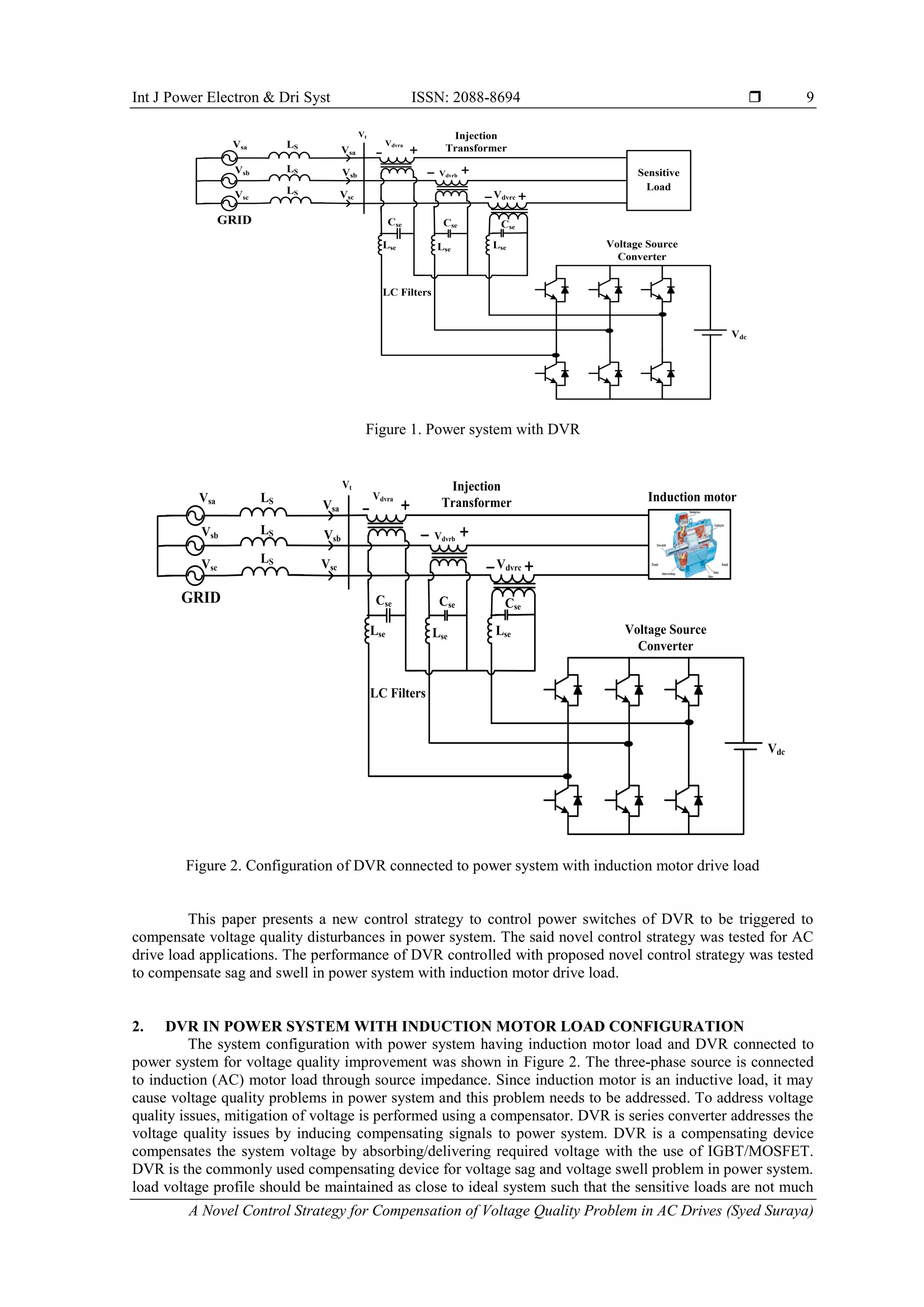
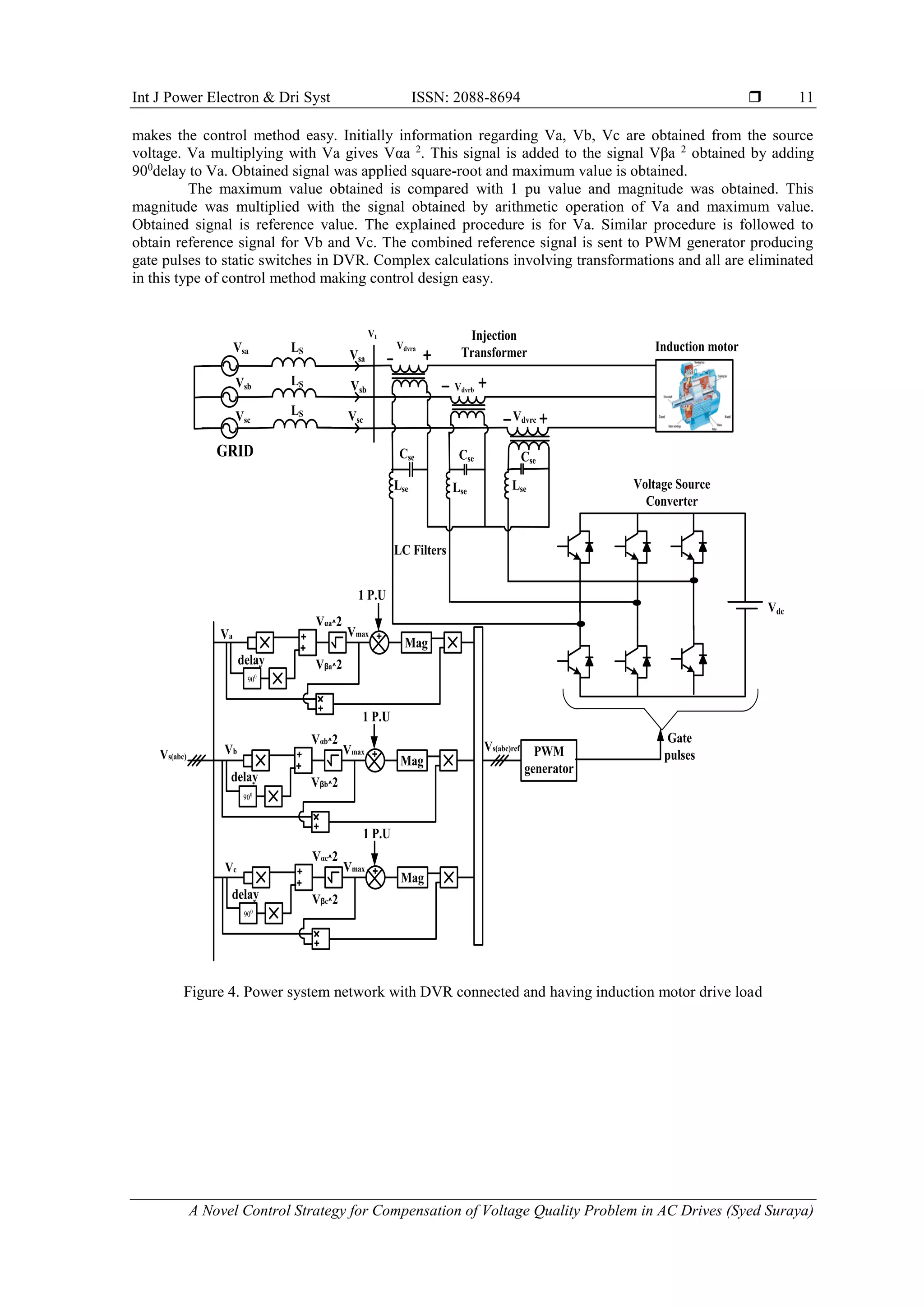
This paper introduces a novel control strategy for a Dynamic Voltage Restorer (DVR) aimed at mitigating voltage quality issues in power systems with AC drives. The proposed strategy effectively compensates for voltage sag and swell by using a combination of power electronics and a control methodology that simplifies the calculations required for operation. The results demonstrate the strategy's effectiveness in maintaining load voltage profiles during various voltage conditions.
![International Journal of Power Electronics and Drive System (IJPEDS)
Vol. 9, No. 1, March 2018, pp. 8~16
ISSN: 2088-8694, DOI: 10.11591/ijpeds.v9.i1.pp8-16 8
Journal homepage: http://iaescore.com/journals/index.php/IJPEDS
A Novel Control Strategy for Compensation of Voltage Quality
Problem in AC Drives
Syed Suraya1
, P. Sujatha2
, P. Bharat Kumar3
Department of Electrical and Electronics Engineering, JNTUA, Ananthpur, AP, India
Article Info ABSTRACT
Article history:
Received Aug 23, 2017
Revised Sep 2, 2017
Accepted Jan 13, 2018
This paper presents a novel control strategy for the compensation of voltage
quality issues in power system networks with AC drives. Voltage quality is
one of the key parameter for power engineers and to deliver the power with
good quality should be given at most priority. Voltage quality mitigation in
power system network is done by employing dynamic voltage restorer
(DVR). DVR consists of power switches and power switches are to be
controlled. DVR in this paper is controlled using a novel control strategy. A
novel control strategy can effectively control DVR by improving voltage
quality reducing the adverse effects of voltage sag and voltage swell in
power system networks. The paper presents the DVR controlled with novel
control strategy for electrical machine (induction motor) drive load
application.
Keyword:
Voltage quality
Compensation
Novel control
AC drives
Copyright © 2018 Institute of Advanced Engineering and Science.
All rights reserved.
Corresponding Author:
Syed Suraya,
Research Scholar,
Departement of Electrical and Electronics Engineering,
JNTUA, Ananthpur, AP, India.
Email: syedsuraya143@gmail.com
1. INTRODUCTION
Consistency is a key word for utilities and their customers in general, and it is crucial to companies
operating in a highly competitive business environment, because it affects profitability, which definitely is a
driving force in the industry. Although electrical transmission and distribution systems have reached a very
high level of reliability, disturbances cannot be totally avoided [1-3]. Power quality issues are not new to
power system but their existence creates new problems due to advancements in power electronic sector.
Voltage quality is the main concern on load side and power engineers should ensure that the load voltage is
same throughout the conditions in power system. Custom power devices might be a solution to eliminate or
reduce power quality problems caused from many loads. FACTS devices are type of custom power devices
employed to reduce the risk of power quality problems using power electronics circuits [4-6].
DVR is one such device used to address voltage sag and swell issues in power system. The DVR is a
power quality device, which can protect these industries against the bulk of these disturbances, i.e. voltage
sags and swells related to remote system faults. A DVR compensates for these voltage excursions, provided
that the supply grid does not get disconnected entirely through breaker trips. DVR [7-8] is power electronic
voltage source converter placed in series to power line as in figure 1 and power switches in DVR is to be
controlled by employing a suitable control strategy to produce gating signals to power switches of DVR [9-
11].](https://image.slidesharecdn.com/02sep23aug8817from15803finaleditlafi-210610033746/75/A-Novel-Control-Strategy-for-Compensation-of-Voltage-Quality-Problem-in-AC-Drives-1-2048.jpg)
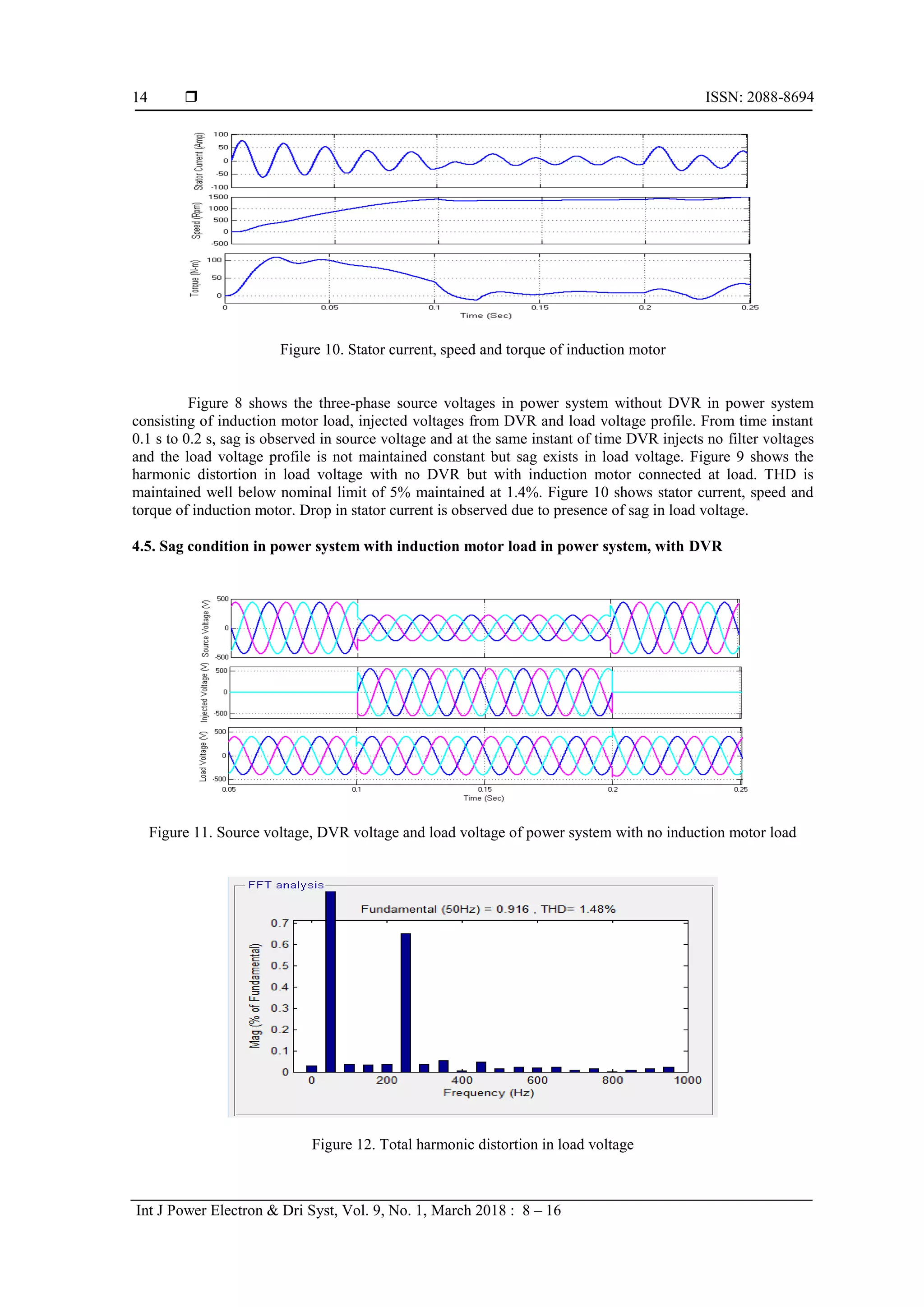
![Int J Power Electron & Dri Syst ISSN: 2088-8694
A Novel Control Strategy for Compensation of Voltage Quality Problem in AC Drives (Syed Suraya)
15
Figure 13. Stator current, speed and torque of induction motor
Figure 11 shows the three-phase source voltages in power system with DVR in power system
consisting of induction motor load, injected voltages from DVR and load voltage profile. From time instant
0.1 s to 0.2 s, sag is observed in source voltage and at the same instant of time DVR injects filter voltages and
the load voltage profile is maintained constant. Figure 12 shows the harmonic distortion in load voltage with
no DVR but with induction motor connected at load. THD is maintained well below nominal limit of 5%
maintained at 1.48%. Figure 13 shows stator current, speed and torque of induction motor. Drop in stator
current is not observed as DVR compensated for sag in source voltage and load voltage.
5. CONCLUSION
The paper presents a novel control strategy to control DVR connected to power system with
induction motor load. The control strategy was tested for sag condition with and without induction motor and
found suitable to control DVR in different test conditions discussed in results. During sag conditions without
and with induction motor, DVR with proposed control strategy injects compensating voltages to maintain
constant load profile.
REFERENCES
[1] Benachaiba, C. and B. Ferdi, 2008. Voltage quality improvement using dynamic voltage restorer. Elect. Power
Quality Utiliz. J., 14: 39-46.
[2] Bollen, M., 1999. Understanding Power Quality Problems: Voltage Sags and Interruptions. 1st Edn., IEEE Press,
Piscataway, NJ., ISBN: 13: 978- 0780347137, pp: 672.
[3] Djokic, S. and J. Milanovic, 2006. Advanced voltage sag characterization. Part I: Phase shift. IEEE Proc. Generat.
Transm. Distribut., 153: 423-430. DOI: 10.1049/ip-gtd:20050350
[4] A. V. Ital and S. A. Borakhade, "Compensation of voltage sags and swells by using Dynamic Voltage Restorer
(DVR)," 2016 International Conference on Electrical, Electronics, and Optimization Techniques (ICEEOT),
Chennai, 2016, pp. 1515-1519
[5] B. P. Ganthia, S. Mohanty, P. K. Rana and P. K. Sahu, "Compensation of voltage sag using DVR with PI
controller," 2016 International Conference on Electrical, Electronics, and Optimization Techniques (ICEEOT),
Chennai, 2016, pp. 2138-2142
[6] S. Singh, V. Rai, A. Kumar and K. B. Sahay, "Simulation and comparison of DVR and D-STATCOM for voltage
sag mitigation," 2016 IEEE 6th International Conference on Power Systems (ICPS), New Delhi, 2016, pp. 1-6.
[7] T. AppalaNaidu, "The Role Of Dynamic Voltage Restorer (DVR) in improving power quality," 2016 2nd
International Conference on Advances in Electrical, Electronics, Information, Communication and Bio-Informatics
(AEEICB), Chennai, 2016, pp. 136-141.
[8] S. Deepika, M. Saranya and V. Poorani, "PI controller based dynamic SAG compensator with PV PANEL: PI
controller based DVR," 2015 International Conference on Advanced Computing and Communication Systems,
Coimbatore, 2015, pp. 1-6.
[9] G. Ramya, V. Ganapathy, P. Suresh, “Power Quality Improvement Using Multi-Level Inverter Based DVR and
DSTATCOM Using Neuro-Fuzzy Controller,” International journal of power electronics and drive systems
(IJPEDS), Vol 8, No 1: March 2017, pp 316-324.
[10] Brahim Ferdi, Samira Dib, Brahim Berbaoui, Rachid Dehini, “Design and Simulation of Dynamic Voltage Restorer
Based on Fuzzy Controller Optimized by ANFIS,” International journal of power electronics and drive systems
(IJPEDS), Vol 4, No 2: June 2014, pp 212-222.](https://image.slidesharecdn.com/02sep23aug8817from15803finaleditlafi-210610033746/75/A-Novel-Control-Strategy-for-Compensation-of-Voltage-Quality-Problem-in-AC-Drives-8-2048.jpg)
![ ISSN: 2088-8694
Int J Power Electron & Dri Syst, Vol. 9, No. 1, March 2018 : 8 – 16
16
[11] D.K. Tanti, M.K. Verma, Brijesh Singh, O.N. Mehrotra, “Optimal Placement of Custom Power Devices in Power
System Network to Mitigate Voltage Sag under Faults,” International journal of power electronics and drive
systems (IJPEDS), Vol 2, No 3: September 2012, pp 267-276.
BIOGRAPHIES OF AUTHORS
Syed Suraya received B.Tech degree in Electrical & Electronics Engineering from
JNTU,Hyderabad in 2002 and M.Tech degree in Energy systems from JNTU,Hyderabad in
2007.She is currently working towards Ph.D degree in Electrical Engineering at JNTUA,
Ananthapuramu.
Her research interests are Non-Conventional Energy, Energy Conservation.
Dr. P. Sujatha presently working as a Professor in Electrical & Electronics Engineering, JNTUA
College of Engineering, Ananthapuramu. She received B. Tech degree in Electrical &
Electronics Engineering from JNTU College of Engineering, Anantapur in 1993, M. Tech degree
in Electrical Power Systems from JNTU College of Engineering, Anantapur in 2003 and Ph. D
in Electrical Engineering from JNTUA, Ananthapuramu in 2012.
Her research interests are: Power Systems, Energy Management and Renewable Energy.
P. Bharat Kumar received B. Tech degree in Instrumentation and Control Engineering from
JNTU Hyderabad in 2007 and M. Tech degree in Control Systems from JNTUA Anantapur. He
is currently working towards the Ph. D. degree in Electrical Engineering at JNTUA
Ananthapuramu.
His research interests include Controllers design using AI techniques, nonlinear control and
Robust Control.](https://image.slidesharecdn.com/02sep23aug8817from15803finaleditlafi-210610033746/75/A-Novel-Control-Strategy-for-Compensation-of-Voltage-Quality-Problem-in-AC-Drives-9-2048.jpg)