Downloaded 16 times
![IOSR Journal of Electrical and Electronics Engineering (IOSR-JEEE)
e-ISSN: 2278-1676,p-ISSN: 2320-3331, Volume 6, Issue 1 (May. - Jun. 2013), PP 06-13
www.iosrjournals.org
www.iosrjournals.org 6 | Page
Transient Stability Enhancement of Grid by Using Fuzzy Logic
Based Statcom
Anil Antony P.1
, R.Punitharaji 2
1. P.G.Student, Paavai Engineering College, Namakkal.
2. Assistant Professor/EEE, Paavai Engineering College, Namakkal.
Abstract-This paper proposes Fuzzy Logic Based STATCOM. It regulates the voltage at the point of common
coupling (PCC) by injecting reactive power. This device also plays a vital role in enhancing stability for small
and large transient disturbances in power system. Simulations using MATLAB / SIMULINK are carried out to
verify the performance of STATCOM using fuzzy controller. The result shows that fuzzy logic controller is a
better choice for the STATCOM compared to the PI controller. Fuzzy logic controller forces the system to
return back the steady state value faster than the PI controller. The fuzzy logic controller is robust and has a
fast response during disturbance and parameters variation. Detailed study of control of STATCOM has been
made, which include analysis of PLL, VSC, mathematical dq transformation has been explained.
Keywords–Static Synchronous Compensator (STATCOM), Pulse-Width Modulation (PWM), Fuzzy logic
controller (FCL), PLL, Regulator,abcto dq transformation, Voltage Source Converter (VSC)
I. Introduction
Transients are always present at each and every movement. During transients voltage level at the grid
gets changed rapidly causing voltage stability problems. The change in voltage at the grid causes rotor angle to
deviate this will cause angle stability problems. Both the voltage and angle are permitted to vary with in some
limits, if it crosses the limits whole the system will get highly unstable. Our power system consist of many
number of generators connected to the grid. Once the stability of any one of the generating unit gets disturbed, it
will gradually disturbs stability of other units connected to the system which that may leads to Cascade tipping
which in turn can causes blackouts.
FACTS controllers can be used to control instabilities caused by transients. STATCOM is one of the
FACTES controller, which is capable of supplying or absorbing reactive power to maintain grid voltage [1]-
[3].it consist of control circuit, voltage source converter (VSC), dc capacitor and coupling transformer. VSC
consist of power electronic devices which are being triggered to perform reactive power transform between grid
and STACTCOM.
Here IGBT‟s are used in VSC, for triggering the gate of IGBT pulse width modulation technique
(PWM) is being used [4]. The input to the PWM generator is controlled by control unit, which uses fuzzy logic
as its controlling technique.Phase lock loop (PLL) has been used to track the phase angle of grid which helps in
synchronising control unit.[5]-[8]
The STATCOM is normally designed to provide fastvoltage control to enhance the stability of system.
Two basic controls are implemented in a STATCOM [2],[3]. The first is the AC voltage regulation across the
gridand second one is the control of the DC voltage across the capacitor. By using the above controller the
active powerinjection from the STATCOM to the grid is being controlled.
Conventionally PI controllers have been use as regulates of STATCOM.Conventional PI controller has
limitation over its operating range. It is highly inefficient during nonlinear operations. Fuzzy logic controller
eliminates the limitations of conventional PI controller [9]-[11].
Mathematical transformation of three phase vector fromabc co-ordinate axis to synchronously rotating
dq axis has been applies for reducing the circuit complexity and easy analysis of the circuit.
The Static Synchronous Compensator (Statcom)
STATCOM from the name itself is a power compensation device, which is capable of compensating
reactive power and real power as well, depending on the circuit configuration. It acts as a shunt compensator.
The basic circuit of STATCOM consist of voltage source converter (VSC), control unit and DC energy source
(mostly capacitor) for VSC. STATCOM is coupled with the grid by using a coupling transformer](https://image.slidesharecdn.com/b0610613-140503014542-phpapp01/85/Transient-Stability-Enhancement-of-Grid-by-Using-Fuzzy-Logic-Based-Statcom-1-320.jpg)
![IOSR Journal of Electrical and Electronics Engineering (IOSR-JEEE)
e-ISSN: 2278-1676,p-ISSN: 2320-3331, Volume 6, Issue 1 (May. - Jun. 2013), PP 06-13
www.iosrjournals.org
www.iosrjournals.org 6 | Page
Transient Stability Enhancement of Grid by Using Fuzzy Logic
Based Statcom
Anil Antony P.1
, R.Punitharaji 2
1. P.G.Student, Paavai Engineering College, Namakkal.
2. Assistant Professor/EEE, Paavai Engineering College, Namakkal.
Abstract-This paper proposes Fuzzy Logic Based STATCOM. It regulates the voltage at the point of common
coupling (PCC) by injecting reactive power. This device also plays a vital role in enhancing stability for small
and large transient disturbances in power system. Simulations using MATLAB / SIMULINK are carried out to
verify the performance of STATCOM using fuzzy controller. The result shows that fuzzy logic controller is a
better choice for the STATCOM compared to the PI controller. Fuzzy logic controller forces the system to
return back the steady state value faster than the PI controller. The fuzzy logic controller is robust and has a
fast response during disturbance and parameters variation. Detailed study of control of STATCOM has been
made, which include analysis of PLL, VSC, mathematical dq transformation has been explained.
Keywords–Static Synchronous Compensator (STATCOM), Pulse-Width Modulation (PWM), Fuzzy logic
controller (FCL), PLL, Regulator,abcto dq transformation, Voltage Source Converter (VSC)
I. Introduction
Transients are always present at each and every movement. During transients voltage level at the grid
gets changed rapidly causing voltage stability problems. The change in voltage at the grid causes rotor angle to
deviate this will cause angle stability problems. Both the voltage and angle are permitted to vary with in some
limits, if it crosses the limits whole the system will get highly unstable. Our power system consist of many
number of generators connected to the grid. Once the stability of any one of the generating unit gets disturbed, it
will gradually disturbs stability of other units connected to the system which that may leads to Cascade tipping
which in turn can causes blackouts.
FACTS controllers can be used to control instabilities caused by transients. STATCOM is one of the
FACTES controller, which is capable of supplying or absorbing reactive power to maintain grid voltage [1]-
[3].it consist of control circuit, voltage source converter (VSC), dc capacitor and coupling transformer. VSC
consist of power electronic devices which are being triggered to perform reactive power transform between grid
and STACTCOM.
Here IGBT‟s are used in VSC, for triggering the gate of IGBT pulse width modulation technique
(PWM) is being used [4]. The input to the PWM generator is controlled by control unit, which uses fuzzy logic
as its controlling technique.Phase lock loop (PLL) has been used to track the phase angle of grid which helps in
synchronising control unit.[5]-[8]
The STATCOM is normally designed to provide fastvoltage control to enhance the stability of system.
Two basic controls are implemented in a STATCOM [2],[3]. The first is the AC voltage regulation across the
gridand second one is the control of the DC voltage across the capacitor. By using the above controller the
active powerinjection from the STATCOM to the grid is being controlled.
Conventionally PI controllers have been use as regulates of STATCOM.Conventional PI controller has
limitation over its operating range. It is highly inefficient during nonlinear operations. Fuzzy logic controller
eliminates the limitations of conventional PI controller [9]-[11].
Mathematical transformation of three phase vector fromabc co-ordinate axis to synchronously rotating
dq axis has been applies for reducing the circuit complexity and easy analysis of the circuit.
The Static Synchronous Compensator (Statcom)
STATCOM from the name itself is a power compensation device, which is capable of compensating
reactive power and real power as well, depending on the circuit configuration. It acts as a shunt compensator.
The basic circuit of STATCOM consist of voltage source converter (VSC), control unit and DC energy source
(mostly capacitor) for VSC. STATCOM is coupled with the grid by using a coupling transformer](https://image.slidesharecdn.com/b0610613-140503014542-phpapp01/75/Transient-Stability-Enhancement-of-Grid-by-Using-Fuzzy-Logic-Based-Statcom-1-2048.jpg)
![Transient Stability Enhancement Of Grid By Using Fuzzy Logic Based Statcom
www.iosrjournals.org 13 | Page
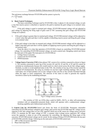
Fig 13: Grid voltage
IV. Conclusion
The main objective of the proposed system is to develop a circuit for enhancing transient stability at 33KV
grid. Fuzzy logic controller was used in controlling STATCOM.It was found that mathematical modelling in
synchronous rotating frame reduces the circuit complexity.PLL have successfully synchronise the control unit
with the grid parameter The experimental results have been analysed with Matlab simulation.Simulation results
analysis has shown that the proposed controller has fast dynamic response, high accuracy of tracking the system
stability, and is robust to load sudden variations.
References
[1] Rajiv Singh, Asheesh Kumar Singh, and Ashutosh Kumar Singh, “Transient Stability Improvement of a FSIG Based Grid Connected
wind Farm with the help of a SVC and a STATCOM: A Comparison”, International Journal of Computer and Electrical Engineering,
February 2012 ,Vol.4, No.1,pp.55-59
[2] PraneshRao, M.L. Crow and Z. Young, “STATCOM control for power system voltage control applications”, IEEE Trans. Power
Delivery , Oct. 2000Vol.15, No.4, pp.1311-1317
.[3] H. Chen, R. Zhou, Y. Wang, Analysis of voltage stability enhancement by robust nonlinear STATCOM control, Proceedings of the
IEEE PES Summer Meeting, 2000, vol. 3, pp. 1924_/ 1929.
[4] Pablo Garefa-Gonzalez and Aurelio Garefa-Cerrada, , “ Control System for a PWM Based STATCOM”, IEEE Transaction Power
Delivery, Oct. 2000 Vol. 15, No.4, pp. 1252-1256.
[5] S. K Chung "A Phase Tracking System for Three Phase Utility Interface Inverters", IEEE Transactions on Power Electronics, May
2000 ,Vol. 15, No. 3, pp:431 - 438.
[6] G. Hsieh, and J.C. Hung, "A Phase-locked loop techniques a survey,",IEEE Transactions on Industrial Electronics, Dec. 1996 , Vol.
43, No. 6, pp:609 - 615.
[7] J. D. Ainsworth, “Phase locked loop oscillator – A new control system for controlled static converters,” IEEE Power Apparat. Syst.,
Mar. 1968,vol. PAS-87, pp. 859–865
[8] M. Karimi-Ghartemani, M.R. Iravani "A method for synchronization of power electronic converters in polluted and variable-
frequency environments", IEEE Transactions on Power Systems, Aug. 2004 , Vol. 19, No. 3, pp:1263- 1270.
[9] C.C. Lee „‟Fuzzy Logic in control systems‟‟, IEEE Transaction on system Man Cybernetics‟, Vol. SMC-20, 1990, PP.1378-1384.
[10] K.L. El-Metwally and O.P. Malik, “Fuzzy Logic Power System Stabilizer”, IEE Proceedings- Generation, Transmission,
Distribution, May 1995,Vol. 142, No. 3, , pp 277-281.
[11] C.C. Lee, “Fuzzy Logic in Control Systems: Fuzzy Logic Controller, Parts I & II”, IEEE Transactions on Systems, Man and
Cybernetics, March/April, 1990, Vol. 20, No. 2,pp 404-435.
Author Profile
Anil Antony P. –He hasreceived the B.Tech degree in Electrical and Electronics Engineering from Jyothi
engineering college, Trissur, Kerala, India under University of Calicut in 2008 and currently perusing M.E. in
Power Systems Engineeringfrom Paavai Engineering College,Namakkal, Tamil Nadu, India under Anna
University, Chennai (2011-2013). During 2009-2011, he has worked as Lecturer in EEE Department under
University of Calicut, Kerala, India.
R.PUNITHARAJI-She hasreceived M.E. in Power Systems Engineering from Sona College of Technologyand
currently working as Assistant Professor in EEE Department in Paavai Engineering College, Namakkal, Tamil
Nadu, India under Anna university, Chennai](https://image.slidesharecdn.com/b0610613-140503014542-phpapp01/85/Transient-Stability-Enhancement-of-Grid-by-Using-Fuzzy-Logic-Based-Statcom-8-320.jpg)

This document discusses enhancing transient stability of the power grid using a fuzzy logic controlled static synchronous compensator (STATCOM). A STATCOM regulates voltage by injecting or absorbing reactive power. It consists of a voltage source converter, control unit, and DC capacitor. The control unit uses fuzzy logic control, abc to dq transformation, phase locked loop, and regulators to control the STATCOM terminal voltage and maintain the grid voltage during transients. Simulations show the fuzzy logic controller provides faster response and is more robust than a PI controller. Detailed explanations are provided of the STATCOM components and control techniques.