Download to read offline
![International Research Journal of Engineering and Technology (IRJET) e-ISSN: 2395 -0056
Volume: 04 Issue: 03 | Mar -2017 www.irjet.net p-ISSN: 2395-0072
© 2016, IRJET | Impact Factor value: 4.45 | ISO 9001:2008 Certified Journal | Page 1637
“Minimizing Penalty in Industrial Power Consumption By
Engaging APFC Unit”: A Review
Nidhi A. Ganatra1 Swati C. Chotaliya2 Prof Vishal N. Jogidas3
1.2B.E in Electrical Engineering, DSTC, Junagadh, Gujarat, India
3. Assistant Professor in Electrical Engineering Department, DSTC, Junagadh, Gujarat, India
---------------------------------------------------------------------***---------------------------------------------------------------------
Abstract-In the industrial sectorthevariousmotoringloads
are continuously running and increasing the inductiveload. So
the power factor in this system get reducesduetotheinductive
reactive power. But the electricity board has a standard limit
regarding the power factor values and if the powerfactorgoes
below the specified limit the electricity company charges the
penalty to the industrial consumers. APFC device reads power
factor from line voltage and line current by determining the
delay in the arrival of the current signal with respect to
voltage signal from the function generator with highaccuracy
by using an internal timer. This time values are the calibrated
as phase angle and corresponding power factor. Then the
values are displayed in Liquid crystal display modules. Then
the motherboard calculates the compensation requirement
and accordingly switches on different capacitor banks. This is
developed by using AVR microcontroller.
KEYWORDS: Power factor, Penalty, AVR microcontroller,
capacitor bank, contactors and current transformer, potential
transformer
1. INTRODUCTION
The low power factor leads to the increase in the load
current, increase in power loss, and decrease in efficiency of
the overall system. In previousvariousmethoduseforpower
factor correction in all this method, the switching of the
capacitor is manual. In this paper we are using a method of
the reactive power compensation by capacitor switching
with automatic control using AVR microcontroller [1].
1.2 POWER FACTOR
Fig -1: Power Triangle
The power factor is the ratio of the active power to the
apparent power .The active power is the real power
delivered to the loads such as motors,lampsetc. Thereactive
power is used just for the purpose of producing magnetic
field for the flow of active power. The apparent power is the
combination of the active and reactive power. The load
current of any motor consist of the resistive component and
inductive component. The inductive component consists of
leakage current and magnetizing current. The leakage
current is totally dependent on the load current but the
magnetizing component is nearby 20 to 60% of the full load
current. The capacitors are employed to reduce inductive
reactance in the induction motor thereby reducing losses in
the supply [2].
Reactive
power
Active power
Apparent
power
Imag current
Motor
current
Work current](https://image.slidesharecdn.com/irjet-v4i3366-171227083802/75/Minimizing-Penalty-in-Industrial-Power-Consumption-by-Engaging-APFC-Unit-A-Review-1-2048.jpg)
![International Research Journal of Engineering and Technology (IRJET) e-ISSN: 2395 -0056
Volume: 04 Issue: 03 | Mar -2017 www.irjet.net p-ISSN: 2395-0072
© 2016, IRJET | Impact Factor value: 4.45 | ISO 9001:2008 Certified Journal | Page 1638
Fig -2: Inductor Current Vector Diagram
1.3 SOURCES OF REACTIVE POWER (INDUCTIVE
LOADS) DECREASE THE POWER FACTOR [3]
-Transformers
-Induction Motors
-Induction generators (wind mill generators)
-High Intensity (HID) lighting
1.4 BENEFITS OF POWER FACTOR CORRECTION
The advantages that can be achieved by applying the
power factor correction are [4]:
Environmental benefit-reduction of power
consumption due to improved energy efficiency.
Reduced power consumption means less
greenhouse gas emissions and fossil fuel depletion
by power stations.
Reduction of electricity bills.
Extra kVA available from the existing supply.
In transformers and distribution equipment I2R
losses decrease.
In long cables reduction of voltage drop.
Extended equipment life- reduced electrical burden
on cables and electrical
Component.
2. PROPOSED SYSTEM
An AVR microcontroller is used in this project as a central
processing unit to calculate the power factor and to switch
the capacitors. The working of this project is explained with
the help of the below block diagram.
Fig -3: Block diagram of PFC using AVR microcontroller
It uses a potential transformer to supply the voltage to the
Resistor divider network (like zero voltage crossing circuit),
which detects the zero crossing of the voltage wave form.
These voltage pulses from the operational amplifier are
applied to the AVR microcontroller as interrupt signals.
Similarly, a current transformer is used here to give the
current wave to the Resistor divider network wherein the
operational amplifier output is enabled for every 10 ms by
comparing the zero position of the current with the
predefined setting. This signal is also applied to the AVR
microcontroller as an interrupt signal. The microcontroller
finds time elapse between these two interrupts and
substitutes it in a certain equation for calculating the power
factor. If this power factor value is above 0.96 then the AVR
doesn’t send any command signals to the relay driver to
switch the capacitors on. But, if it is less than 0.96, then the
AVR sends command signals to the relay driver so that the
capacitor bank on. Therefore, these capacitors reduce the
lagging nature of the load by giving leadingcurrentstoit. The
number of capacitors’ switching depends on the value of the
power factor – very low power factor needs all the capacitor,
whereas high power factor needs none of those.
2.1 HARDWARE
Fig -4: Hardware setup
The proposed work can be explained in the form of block
diagram as shown in figure 3. It comprises of following 9
blocks [1],
CT & PT
Comparator unit](https://image.slidesharecdn.com/irjet-v4i3366-171227083802/75/Minimizing-Penalty-in-Industrial-Power-Consumption-by-Engaging-APFC-Unit-A-Review-2-2048.jpg)
![International Research Journal of Engineering and Technology (IRJET) e-ISSN: 2395 -0056
Volume: 04 Issue: 03 | Mar -2017 www.irjet.net p-ISSN: 2395-0072
© 2016, IRJET | Impact Factor value: 4.45 | ISO 9001:2008 Certified Journal | Page 1640
3. CONCLUSION
In our project “Minimizing Penalty in Industrial Power
Consumption by Engaging APFC Unit” in whichtheadvanced
method of the power factor correction by using the AVR and
Automatic power factor correction unit which has the many
advantages over the various methods of the power factor
correction. The switching of capacitorsisdoneautomatically
by using the contactors and thus the power factor correction
is more accurate. Thus in this paper presented the possible
advanced method for the correction of the power factor.
REFERENCE
[1] Sagar Jundare,PranavUkkadgaonkar,MinimizingPenalty
in Industrial sector By Engaging Automatic powercorrection
panel using microcontroller.
[2] https://en.wikipedia.org/wiki/Power_factor
[3]http://www.electricaltechnology.org/2013/10/causes-
of-low-power-factor.html
[4] Power factor correction By John Ware
[5]Muhammad Ali Mazidi and Janice Gillespie Mazidi,
“Microcontroller and Embedded Systems”.
[6] IEEE TRANSACTIONSON INDUSTRIAL ELECTRONIC VOL
NO 3FEBRUARY 1990 77A Microprocessor-Based Adaptive
Power Factor Corrector for Nonlinear Loads H. M.
ELBOLOK,M. E. MASOUD, AND M. M.MAHMOU
[7] P. N. Enjeti and R artinez “A high performance single
phase rectifier with input power factor correction”, IEEE
Trans. Power Electron…vol.11, No.2, Mar.2003.pp 311-317
BIOGRAPHIES
I, Nidhi Ganatra, am a
final year student of
Electrical. Dept. in Dr.
Subhash technical
campus Junagadh.
I, Swati Chotaliya, am
a final year student of
Electrical. Dept. in Dr.
Subhash technical
campus Junagadh.
I, Vishal N. jogidas am a,
Assistant Professor in
the Department of
Electrical Engineering,
Dr. Subhash Technical
campus Junagadh.](https://image.slidesharecdn.com/irjet-v4i3366-171227083802/75/Minimizing-Penalty-in-Industrial-Power-Consumption-by-Engaging-APFC-Unit-A-Review-4-2048.jpg)

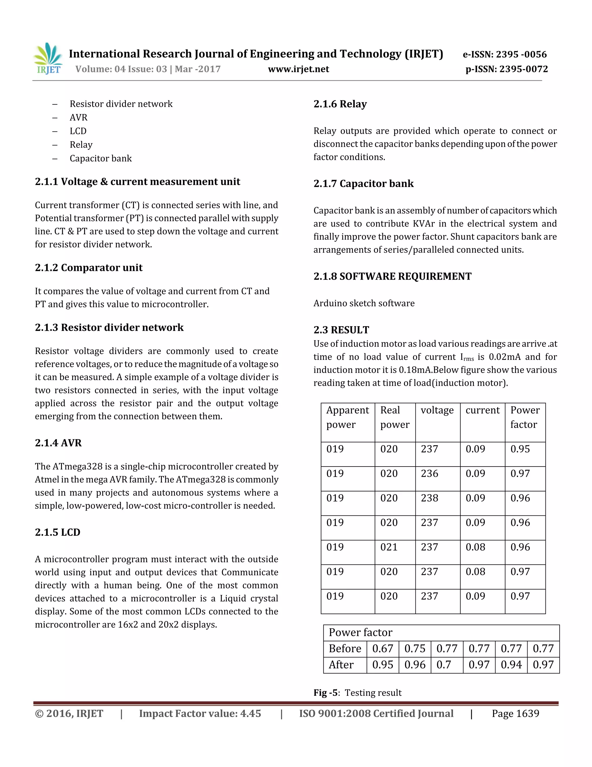
This document summarizes a research paper on minimizing penalties in industrial power consumption by using automatic power factor correction (APFC) units. It discusses how inductive loads in industries reduce the power factor below standards set by electricity boards, resulting in penalties. An APFC device uses a microcontroller to measure voltage, current, power factor and automatically switch capacitor banks to compensate for reactive power and improve the power factor. Test results showed the power factor increased from 0.67 to 0.95 after installing the APFC unit, reducing penalties for the industrial consumer. The automatic switching of capacitors provides a more accurate method of power factor correction compared to manual switching.


![Seller Deck - Presentation [Concert L2].PPTX](https://cdn.slidesharecdn.com/ss_thumbnails/sellerdeck-presentationconcertl2-251219171156-24982daf-thumbnail.jpg?width=640&height=640&fit=bounds)


