Factory owners must ensure boilers are properly maintained and operated safely. Key responsibilities include registering the boiler, ensuring regular inspections by an appointed examiner, having a competent person supervise the boiler whenever it is steaming, and maintaining the boiler in safe working order. The document provides guidance on safe boiler operation, maintenance, and emergency procedures to prevent accidents. It emphasizes the importance of proper training and compliance with regulations.
A $1.6 million settlement was reached in a boiler explosion case where a man suffered severe injuries. Boiler explosions and fires have injured many people in the last ten years due to lack of safety training. A 1999 explosion at a power plant killed 6 people and injured 30. Proper boiler safety requires management leadership, hazard prevention, education and training to prevent accidents. The top causes of boiler accidents are issues with maintenance, lockout procedures during startup, falls, carbon monoxide exposure, and fly ash hazards.
MAN B&W introduced new slide fuel valves that require a new testing criterion. To meet this, Obel-P offers two new product solutions: 1) a new test pump unit that prevents damaging the slide valves by making atomization tests impossible, and 2) a lower-cost adapter unit that can be used with existing test rigs to achieve the same result. The document then provides details on the technical specifications and operating procedures for both solutions to allow for safe testing of the new slide fuel valves without risk of damage.
Boiler recommissioning procedure after capital overhaul Manohar Tatwawadi
In a thermal power plant, boiler overhauling is generally done yearly. The presentation highlights the procedure for the re-commissioning of the boiler after capital overhaul.
1. The document discusses various boiler emergency situations during operation with an emphasis on safety aspects like boiler protection systems and controls. It provides descriptions of potential causes, effects, and recommended actions for issues like low or high drum level, high furnace draft, flame failure, boiler feed pump failure, high boiler pressure, furnace explosion, tube failures, coal feeder or burner trips, and more. The goal is to safely manage emergencies and prevent damage to the boiler.
This document provides a short guide to API 682 plans and operational information for mechanical seals and supply systems. It summarizes various API plans for sealing technology, including plans for clean media, media with solids, and hazardous media. For each plan, it describes the media characteristics, start-up, shut-down, and regular inspection procedures, as well as potential troubleshooting issues and solutions. The document also includes connection codes, PID codes, and terminology used in the short guide.
The document provides instructions for hydrostatic testing circulating fluidized bed units. It outlines procedures for filling the unit with treated water, performing the hydrostatic test at 1.5 times the design pressure, and post-test procedures like pressurizing the unit with nitrogen and removing test plugs from safety valves. The key requirements are to fill the superheater and boiler with treated water, test to at least 1.5 times the design pressure, and pressurize the unit with nitrogen after testing.
This document outlines rules and regulations regarding boilers in the Philippines, as established by the Department of Labor and Employment. It defines various types of boilers, including steam boilers, power boilers, miniature boilers, and hot water boilers. It establishes requirements for boiler construction, inspection, safety systems, and operation, in accordance with international standards. Owners must apply for permits, keep records, and allow regular inspections to ensure boilers are safely constructed and maintained.
This document provides guidance on general boiler operations, with a focus on initial commissioning operations. It discusses key considerations for operator training and equipment preparation prior to startup. The document outlines a systematic approach for boiler startup, including inspection, cleaning, testing, and adjustments. Fundamental operating principles like combustion safety and steam/water cooling requirements are also covered. The goal is to safely optimize equipment performance and reliability.
Pre commissioning steam turbines load trialNagesh H
The document discusses pre-commissioning and commissioning activities for a steam turbine. Pre-commissioning includes steam blowing of lines, condenser testing like leak and vacuum drop tests, checking bearing clearances and dumps, setting throttle valves, and verifying safety trips. Commissioning procedures cover starting the turbine in solo run and load run modes while monitoring vibration levels and other parameters. Load trial data is collected and actual steam consumption is compared to projected values, with correction factors applied. Problems faced on site included low dump values due to nozzle chest welding issues and high CEP current due to pump-motor misalignment.
This document provides the steps and estimated times for a 2L PET cold caustic CIP (clean-in-place) changeover. It involves 15 steps including draining and flushing the filler, filling and draining the carbo-cooler tank twice, switching to a CO2 supply, flushing the filler with product, and conducting a test run to start production. The total estimated time is 1 hour and 40 minutes with the CIP itself taking approximately 45 minutes.
EKIT (B) Sdn Bhd is able to provide one stop solution for hydro-testing jobs for the Oil & Gas industry.
Unique Hydrostatic Pressure Testing.
www.ekitbrunei.com
INTRODUCTION
UNPACKINGAND
CHECKING
INSTALLATION 111: 1 CONNECTION
FUNCTION IV:1 1040 EXTRACTION UNIT
IV:2 1041 SERVICE UNIT
IV:3 EXTRACTION CUPS AND CUP HOLDER
IV:4 THIMBLE AND THIMBLE ADAPTERS
IV:5 THIMBLE SUPPORT WITH HOLDER AND THIMBLE
STAND
IV:6 THIMBLE HANDLER AND TONGS FOR EXTRACTION
CUPS
WTM WLM OPERATION
V:1
V:2
V:3
V:4
V:5
PREPARATION OF SAMPLE
STARTING UP
EXTRACTION
SOLVENT RECOVERY, REMOVAL OF THIMBLES
AND EXTRACTION CUPS
SHUT DOWN
The presentation discuss about the operations, causes and remedies for the facing emergencies of steam Turbines. Specially for the 210MW LMW units. The emergencies can be created on simulator and studied on the simulator ACCORDINGLY.
The document provides information about the boiler feed water pump system used in a power plant, including its purpose, components, technical specifications, maintenance procedures, and troubleshooting guidelines. The system consists of a booster pump and larger feed water pump coupled together and driven by a single electric motor. Key components are described in detail, such as the pumps, turbo coupling, motor, and balancing device. Periodic maintenance tasks and clearances are outlined. Common issues that may arise are identified along with recommended solutions.
Ray Beebe has over 50 years of experience in power generation and condition monitoring of steam turbines. He discusses several case studies where condition monitoring helped identify issues in steam turbines. Condition monitoring techniques like vibration analysis, performance analysis of parameters like valve output, stage pressures and enthalpy drop efficiency can help detect problems like blade deposits or damage. The case studies show how condition monitoring helped detect issues and schedule repairs before further degradation occurred. Mr. Beebe emphasizes that condition monitoring data should be used to only open turbines for repair when there are clear technical and economic reasons to do so.
This document outlines the procedure for conducting a hydrotest/water fill-up test of a tank. It details the preparation steps like ensuring all welding and NDT work is complete. The test will be done using portable water and in stages, filling to 25%, 50%, 75% and 100% and observing for 24 hours between each stage. Settlement will be measured throughout and records submitted after draining and cleaning the tank. Safety precautions must be followed during the water filling test.
Medical gas supply systems provide gases to hospitals through cylinders and pipelines. Cylinders contain gases like oxygen, nitrous oxide, and air in compressed form. They have steel bodies, valves to fill and release gas, and pressure relief devices. Pipelines distribute gases from a central source through a main line, risers, and branch lines to terminal units where gases are delivered. Terminal units have automatic shut-off valves and gas-specific connectors to prevent mixing of different gases. Extensive testing ensures medical gas pipelines deliver the proper gas at adequate pressures and purity levels to support patient care.
Fire pumps are pumps certified to NFPA 20 standards that provide reliable water supply for fire protection systems. They enhance water pressure and cannot create water flow. Fire pumps require regular inspection and testing to verify they are operating properly and free of issues. Weekly inspections include checking components like valves, gauges, fuel levels, and batteries, while weekly tests involve starting the pump without water flow to check for abnormal noises, vibrations, or overheating that could indicate maintenance is needed.
This document provides information about the basic components and functioning of an anaesthesia machine. It discusses the key components of the machine's pneumatic and electrical systems. The pneumatic system includes the high pressure, intermediate pressure and low pressure systems which are responsible for delivering precisely controlled gas mixtures from pressurized cylinders or central pipelines. The electrical components power and monitor the machine. The document also provides details on cylinders, pressure regulators and other individual parts that make up the overall anaesthesia machine.
The document summarizes a vendor visit by an engineering company to BÖHMER GmbH in Germany to evaluate subsea valves. It includes sections on general information, applicable standards, document review, test criteria and descriptions of hydrostatic, function, pneumatic and drift tests performed on 6" and 2" ball valves. Test parameters and acceptance criteria are defined according to API 6DSS and the client's specification. The 27-page report provides technical details to verify the valves meet design and performance requirements for a subsea pipeline project in Nong Yao, China.
I am Pravin Xavier, I had around 12 years experience in Oil and Gas. right now I am looking for a job. I have good knowledge in Production / Process and commissioning so If any openings kindly let me know. I ready to join immediately.
During the past and present career, experienced in the following areas.
1) Commissioning, 2) Jetty Operation, 3) Well Head Operations, 4) Separators, 5) Crude Oil Stabilization Unit, 6) Oil & Gas Gathering Station, 7) Gas Dehydration & Amine Sweetening unit, 8) Gas Plant Operation 9) Hot Oil Unit, 10) Boiler & heater Treatment 11) Central Production Facility and Tank Farm, 12) DCS experience, 13) Compressors, 14) Pump Operation 15) Pigging Operation 16) Chemicals Handled
Thanks & Regards
PRAVIN XAVIER .R
Mob. - 0091 9994774530
Skype - pravinxavier.r
This document discusses operation and maintenance of different valve types used in reciprocating compressors. It begins with an introduction of the COP® poppet valve, outlining its design and history. Field experience shows poppet valves outperform traditional plate and ring valves in applications with contaminated gases and over a wide speed range. Poppet valves typically last 8,000-15,000 hours depending on the application, outlasting plate valves which may only achieve 4,000-8,000 hours. The document provides maintenance guidelines and compares expected lifetimes of plate, ring, and poppet valves in different compressor applications. Proper valve selection and maintenance are important to maximize reliability and efficiency.
Cb gf web in aug 2016, controls r2 8.23.16 finallorenzo Monasca
Como controlar el nivel de agua de la calderas y los metodos de control mas conveniente. Esta presentacion con los expertos de Cleaver brooks y Grundfos te dan los mejores alternativas para controlar el nivel de agua de las calderas.
Steam blowing stages before turbine rollingabhinav kumar
Steam blowing is carried out to remove welding slag, debris, and other foreign materials from turbine system piping generated during manufacturing and construction. It uses high velocity steam to purge lines through either puffing method, which uses thermal shocks, or continuous blowing method. The process is done in stages, with target plates used to evaluate cleanliness. The lines blown include steam, reheat, bypass, and other auxiliary lines. Blowing is completed when target plates show acceptable levels of debris indentation.
This document provides information on valves and valve products from AZ-Armaturen. It describes various types of plug valves, ball valves, butterfly valves, and other specialty valves that are chemical resistant, durable, and approved for various industrial applications and standards. AZ-Armaturen has production facilities around the world and offers a wide range of valve customization, testing, and certification options to meet customers' highest demands.
This document provides installation, operation and maintenance instructions for Bharat Heavy Electricals Limited 1700 series safety valves. It describes the design features of the valves including materials used, service life considerations and temperature compensation. It provides guidelines for handling, storage, installation, setting the popping pressure, maintenance, testing and repair of the safety valves. The document aims to ensure the safe and proper use of the safety valves.
This document provides guidelines for safely handling compressed gas cylinders. It discusses identifying gas contents, securing cylinders, opening valves slowly, using proper fittings and equipment, checking for leaks, closing valves when not in use, storing cylinders properly, transporting cylinders carefully, and returning empty cylinders to suppliers. Safety precautions are outlined for flammable, toxic, and reactive gases.
The document discusses boiler safety, including necessary safety apparatuses, safety valves, their purpose and requirements. It provides definitions of key terms, markings required on safety valves, number of safety valves needed, and summarizes a case study of a boiler explosion highlighting causes and recommended measures.
This document provides instructions for starting up a steam turbine. It outlines the sequence of operations that must be followed, including: opening drains, charging the steam line, starting the cooling water system, operating the condensate system, starting the oil system, putting the turbine on barring, building vacuum, charging gland steam, rolling the turbine, and synchronizing once full speed is reached. Special attention is given to ensuring auxiliary systems are operational and parameters are within limits at each stage to safely start the turbine.
The document provides information on commissioning a hydro power station. It discusses the key components of a hydroelectric power plant and outlines the main commissioning activities, which include pre-commissioning tests, initial run tests, and test runs. The pre-commissioning tests check equipment functionality before and after filling the waterways. Initial run tests slowly increase the turbine speed. Test runs involve mechanical spinning without excitation, spinning with excitation, synchronization with the grid, and load run and rejection tests to check performance and response at various load levels.
This document discusses maintenance inspection and safety precautions for boilers according to the Indian Boiler Regulations (IBR). It provides instructions on checking the boiler lagging, furnace tubes, cleanliness and efficiency of the economizer. It also mentions repairing cracked furnace plates or bricks. Safety precautions include operating the boiler within its safe pressure limit, obtaining registration and an inspection certificate, and following all rules and regulations outlined in the IBR. Failure to do so could result in dangerous bursting and prosecution.
This document discusses API piping plans for mechanical seal flushing arrangements. It provides descriptions and guidelines for 15 standardized API plans that are widely used in industry to circulate fluid for seal cooling and lubrication. The plans involve arrangements like internal and external recirculation lines, strainers, flow control orifices, heat exchangers, and dual seal barrier fluid systems. Caution is given about design considerations like pressure differentials, flow rates, and fluid compatibility for each plan.
API682 Mechanical Seal Plan and Requirements of Mechanical SealsElango Palaniappan
This document summarizes several standardized piping plans defined by API 682 4th edition for mechanical seal flushing arrangements. It describes 15 different piping plans that provide recirculation of process fluid to cool and vent the mechanical seal. Each plan includes a brief description of its features, typical uses, and important cautions. Customer-specific variants of the standardized plans are also possible. Contact information is provided for further details.
The document discusses how to test the low-pressure circuit of an anesthesia machine. It describes how leaks can occur and methods to test for leaks, including positive and negative pressure leak tests. It emphasizes that machines with check valves must use a negative pressure test. Several components are tested, including the vaporizers, flow tubes, and check valves. Proper testing of the low-pressure circuit is important to ensure no leaks that could cause hypoxia or patient awareness.
The document discusses various boiler mountings, which are crucial components that allow boilers to operate safely. It describes key mountings like safety valves, water level indicators, pressure gauges, and their functions. Safety valves in particular are discussed in depth, including their construction, types, setting pressures, testing procedures, and regulations. Maintaining proper boiler mountings is important for safety and optimal boiler performance.
This document outlines procedures for filling SCUBA cylinders with a Bauer VA-13 breathing air compressor at the Newport Aquarium. Only trained employees are authorized to operate the compressor. Pre-operation checks of the compressor include verifying the oil level and emptying the waste water tank. Cylinders are filled one at a time by connecting them to the fill whip and slowly opening valves until full. Proper documentation of training and fills is maintained.
Hazard operability study - in Industires and plantJayaKarthic1
The Hazard and Operability (HAZOP) analysis technique is used to identify safety hazards and operability problems in a process plant that could compromise productivity or lead to undesirable consequences. A multi-disciplinary team uses a systematic approach and guide words like "no," "more," and "less" to examine how deviations from the design intent could occur. The team conducted a HAZOP study on a 1 MT benzol plant, identifying deviations and their causes and consequences for processes like transferring benzol to a reboiler. Key findings included pump seal leaks, improper equipment earthing, unscreened vents, and needed instrument maintenance. Recommendations focused on replacing seals, improving grounding, adding vent screens, and
The Hazard and Operability (HAZOP) analysis technique is used to identify safety hazards and operability problems in a process plant that could compromise productivity or lead to undesirable consequences. A multi-disciplinary team uses a systematic approach and guide words like "no," "more," and "less" to examine how deviations from the design intent could occur. The team conducted a HAZOP study on a 1 MT Benzol plant, identifying deviations and their causes and consequences for processes like transferring benzol to a reboiler. Key findings included pump seal leaks, improper equipment earthing, unscreened vents, and needed instrument and flange maintenance. Recommendations addressed replacing seals, proper grounding, vent screening
This document provides information about boiler surveys. It discusses the reasons for surveys, types of surveys including internal examinations and testing of safety valves. It provides details on survey requirements from regulatory bodies like SOLAS and IACS. Survey preparation steps are outlined, including cleaning, isolating the boiler, and having equipment ready. Various boiler components are also described such as composite boilers, water tube boilers, exhaust gas boilers, and common fittings like sight glasses and safety valves.
Hyster b214 (h450 hds ec) forklift service repair manualuufdjjjskkemm
1. The document provides repair procedures for the frame, counterweight, covers, floor plates, handrails, steps, hydraulic tank, and fuel tank of various lift truck models.
2. The frame is a one-piece weldment that mounts various components and has specific points to mount the main counterweight, engine, transmission, and other parts.
3. The counterweight repair section provides instructions for removing and installing the main counterweight, which varies in weight between 6,000kg to 8,450kg depending on the lift truck model.
Hyster b214 (h500 hd ec) forklift service repair manualufjkskemfseol
1. The document provides repair procedures for the frame, counterweight, covers, floor plates, handrails, steps, hydraulic tank, and fuel tank of various lift truck models.
2. The frame is a one-piece weldment that mounts various components and has a main counterweight weighing between 6,000-8,450 kg depending on the model.
3. Removal and installation procedures are provided for components including the counterweight, air cleaner, hoods, floor plates, and hydraulic tank.
Hyster b214 (h450 hds ec) forklift service repair manualfujsjefkskem
1. The document provides repair procedures for the frame, counterweight, covers, floor plates, handrails, steps, hydraulic tank, and fuel tank of various lift truck models.
2. The frame is a one-piece weldment that mounts various components and has a counterweight ranging from 6,000 to 8,450 kg depending on the model.
3. Counterweight removal requires a lifting device and removal of mounting hardware, while installation requires aligning and reinstalling the hardware.
Hyster b214 (h500 hd ec) forklift service repair manualfhjsekfksemert
The document provides repair procedures for the frame, counterweight, covers, floor plates, handrails, steps, hydraulic tank, and fuel tank of lift trucks. It describes the components of the frame and how to remove and install the counterweight. It also details how to remove and install the air cleaner, hoods, covers, floor plates, handrails, steps, hydraulic tank, and fuel tank. Procedures are provided for cleaning, repairing leaks, and installing these components.
Hyster b214 (h450 hds ec) forklift service repair manualfjkskmmdmme
1. The document provides repair procedures for the frame, counterweight, covers, floor plates, handrails, steps, hydraulic tank, and fuel tank of various lift truck models.
2. The frame is a one-piece weldment that mounts various components and has specific points to mount the main counterweight, engine, transmission, and other parts.
3. The counterweight repair section provides instructions for removing and installing the main counterweight, which varies in weight between 6,000kg to 8,450kg depending on the lift truck model.
Hyster b214 (h500 hd ec) forklift service repair manualfusjefjskefkksem
The document provides repair procedures for the frame, counterweight, covers, floor plates, handrails, steps, hydraulic tank, and fuel tank of lift trucks. It describes the components of the frame and provides instructions for removing and installing the counterweight, air cleaner, hoods, floor plates, and hydraulic tank. The hydraulic tank repair section gives directions for cleaning, repairing leaks, and reinstalling the hydraulic tank. Fuel tank repair is also addressed. Safety warnings are provided throughout regarding working with heavy components, hot fluids, welding, and fuel vapors.
Hyster b214 (h450 hds ec) forklift service repair manualfjsjekdmmeme
1. The document provides repair procedures for the frame, counterweight, covers, floor plates, handrails, steps, hydraulic tank, and fuel tank of various lift truck models.
2. The frame is a one-piece weldment that mounts various components and has specific points to mount the main counterweight, engine, transmission, and other parts.
3. The counterweight repair section provides instructions for removing and installing the main counterweight, which varies in weight between 6,000kg to 8,450kg depending on the lift truck model.
Hyster b214 (h500 hd ec) forklift service repair manualujdjfjkskmdm
1. The document provides repair procedures for the frame and connected parts of various lift truck models, including the frame, counterweight, covers, floor plates, handrails, steps, hydraulic tank, and fuel tank.
2. The counterweight repair section describes how to remove and install the main counterweight, which weighs between 6,000kg and 8,450kg depending on the lift truck model.
3. The hydraulic tank repair section outlines how to remove and install the 153kg hydraulic tank, which contains 321 liters of hydraulic oil and requires draining the oil before removal.
Similar to A guide for firetube boiler testes (20)
TIME DIVISION MULTIPLEXING TECHNIQUE FOR COMMUNICATION SYSTEMHODECEDSIET
Time Division Multiplexing (TDM) is a method of transmitting multiple signals over a single communication channel by dividing the signal into many segments, each having a very short duration of time. These time slots are then allocated to different data streams, allowing multiple signals to share the same transmission medium efficiently. TDM is widely used in telecommunications and data communication systems.
### How TDM Works
1. **Time Slots Allocation**: The core principle of TDM is to assign distinct time slots to each signal. During each time slot, the respective signal is transmitted, and then the process repeats cyclically. For example, if there are four signals to be transmitted, the TDM cycle will divide time into four slots, each assigned to one signal.
2. **Synchronization**: Synchronization is crucial in TDM systems to ensure that the signals are correctly aligned with their respective time slots. Both the transmitter and receiver must be synchronized to avoid any overlap or loss of data. This synchronization is typically maintained by a clock signal that ensures time slots are accurately aligned.
3. **Frame Structure**: TDM data is organized into frames, where each frame consists of a set of time slots. Each frame is repeated at regular intervals, ensuring continuous transmission of data streams. The frame structure helps in managing the data streams and maintaining the synchronization between the transmitter and receiver.
4. **Multiplexer and Demultiplexer**: At the transmitting end, a multiplexer combines multiple input signals into a single composite signal by assigning each signal to a specific time slot. At the receiving end, a demultiplexer separates the composite signal back into individual signals based on their respective time slots.
### Types of TDM
1. **Synchronous TDM**: In synchronous TDM, time slots are pre-assigned to each signal, regardless of whether the signal has data to transmit or not. This can lead to inefficiencies if some time slots remain empty due to the absence of data.
2. **Asynchronous TDM (or Statistical TDM)**: Asynchronous TDM addresses the inefficiencies of synchronous TDM by allocating time slots dynamically based on the presence of data. Time slots are assigned only when there is data to transmit, which optimizes the use of the communication channel.
### Applications of TDM
- **Telecommunications**: TDM is extensively used in telecommunication systems, such as in T1 and E1 lines, where multiple telephone calls are transmitted over a single line by assigning each call to a specific time slot.
- **Digital Audio and Video Broadcasting**: TDM is used in broadcasting systems to transmit multiple audio or video streams over a single channel, ensuring efficient use of bandwidth.
- **Computer Networks**: TDM is used in network protocols and systems to manage the transmission of data from multiple sources over a single network medium.
### Advantages of TDM
- **Efficient Use of Bandwidth**: TDM all
Batteries -Introduction – Types of Batteries – discharging and charging of battery - characteristics of battery –battery rating- various tests on battery- – Primary battery: silver button cell- Secondary battery :Ni-Cd battery-modern battery: lithium ion battery-maintenance of batteries-choices of batteries for electric vehicle applications.
Fuel Cells: Introduction- importance and classification of fuel cells - description, principle, components, applications of fuel cells: H2-O2 fuel cell, alkaline fuel cell, molten carbonate fuel cell and direct methanol fuel cells.
Advanced control scheme of doubly fed induction generator for wind turbine us...IJECEIAES
This paper describes a speed control device for generating electrical energy on an electricity network based on the doubly fed induction generator (DFIG) used for wind power conversion systems. At first, a double-fed induction generator model was constructed. A control law is formulated to govern the flow of energy between the stator of a DFIG and the energy network using three types of controllers: proportional integral (PI), sliding mode controller (SMC) and second order sliding mode controller (SOSMC). Their different results in terms of power reference tracking, reaction to unexpected speed fluctuations, sensitivity to perturbations, and resilience against machine parameter alterations are compared. MATLAB/Simulink was used to conduct the simulations for the preceding study. Multiple simulations have shown very satisfying results, and the investigations demonstrate the efficacy and power-enhancing capabilities of the suggested control system.
A review on techniques and modelling methodologies used for checking electrom...nooriasukmaningtyas
The proper function of the integrated circuit (IC) in an inhibiting electromagnetic environment has always been a serious concern throughout the decades of revolution in the world of electronics, from disjunct devices to today’s integrated circuit technology, where billions of transistors are combined on a single chip. The automotive industry and smart vehicles in particular, are confronting design issues such as being prone to electromagnetic interference (EMI). Electronic control devices calculate incorrect outputs because of EMI and sensors give misleading values which can prove fatal in case of automotives. In this paper, the authors have non exhaustively tried to review research work concerned with the investigation of EMI in ICs and prediction of this EMI using various modelling methodologies and measurement setups.
Comparative analysis between traditional aquaponics and reconstructed aquapon...bijceesjournal
The aquaponic system of planting is a method that does not require soil usage. It is a method that only needs water, fish, lava rocks (a substitute for soil), and plants. Aquaponic systems are sustainable and environmentally friendly. Its use not only helps to plant in small spaces but also helps reduce artificial chemical use and minimizes excess water use, as aquaponics consumes 90% less water than soil-based gardening. The study applied a descriptive and experimental design to assess and compare conventional and reconstructed aquaponic methods for reproducing tomatoes. The researchers created an observation checklist to determine the significant factors of the study. The study aims to determine the significant difference between traditional aquaponics and reconstructed aquaponics systems propagating tomatoes in terms of height, weight, girth, and number of fruits. The reconstructed aquaponics system’s higher growth yield results in a much more nourished crop than the traditional aquaponics system. It is superior in its number of fruits, height, weight, and girth measurement. Moreover, the reconstructed aquaponics system is proven to eliminate all the hindrances present in the traditional aquaponics system, which are overcrowding of fish, algae growth, pest problems, contaminated water, and dead fish.
Optimizing Gradle Builds - Gradle DPE Tour Berlin 2024Sinan KOZAK
Sinan from the Delivery Hero mobile infrastructure engineering team shares a deep dive into performance acceleration with Gradle build cache optimizations. Sinan shares their journey into solving complex build-cache problems that affect Gradle builds. By understanding the challenges and solutions found in our journey, we aim to demonstrate the possibilities for faster builds. The case study reveals how overlapping outputs and cache misconfigurations led to significant increases in build times, especially as the project scaled up with numerous modules using Paparazzi tests. The journey from diagnosing to defeating cache issues offers invaluable lessons on maintaining cache integrity without sacrificing functionality.
Understanding Inductive Bias in Machine LearningSUTEJAS
This presentation explores the concept of inductive bias in machine learning. It explains how algorithms come with built-in assumptions and preferences that guide the learning process. You'll learn about the different types of inductive bias and how they can impact the performance and generalizability of machine learning models.
The presentation also covers the positive and negative aspects of inductive bias, along with strategies for mitigating potential drawbacks. We'll explore examples of how bias manifests in algorithms like neural networks and decision trees.
By understanding inductive bias, you can gain valuable insights into how machine learning models work and make informed decisions when building and deploying them.
Using recycled concrete aggregates (RCA) for pavements is crucial to achieving sustainability. Implementing RCA for new pavement can minimize carbon footprint, conserve natural resources, reduce harmful emissions, and lower life cycle costs. Compared to natural aggregate (NA), RCA pavement has fewer comprehensive studies and sustainability assessments.
2. Factory owners must ensure the boiler is:─
* Registered with the Boilers and Pressure Vessels Division, Labour Department
* Examined by an appointed examiner and has a valid certificate of fitness
* Supervised by a competent person whenever it is steaming
* In safe working order
* Properly maintained through regular periodic internal examinations every 14
months by an appointed examiner
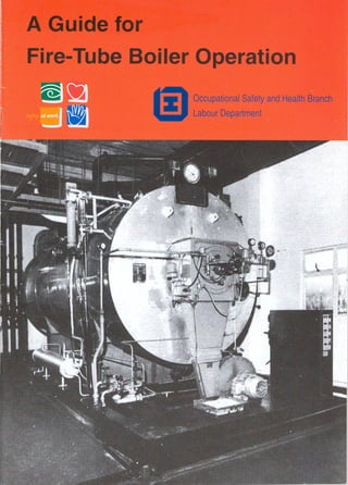
3. A Guide for Fire-tube Boiler Operation
Boilers and Pressure Vessels Authority
Labour Department
May 1993
4. Printed by the Printing Department
(Printed with environmentally friendly ink on paper made
from woodpulp derived from renewable forests)
5. 3
FOREWORD
This guide explains the main provisions of the Boilers and Pressure Vessels
Ordinance, Chapter 56, as applicable to fire tube steam boilers. Essentials of
operation are also briefly explained.
This equipment is extensively used in industry and insufficient knowledge
about its operation and proper maintenance has caused serious accidents. All
personnel engaged in the use of such equipment are strongly advised to
familiarise themselves with the contents of this guide.
This guide is not meant to replace the Ordinance or the maker's manuals
which remain the final authority for regulating operation of this equipment.
On request, the Labour Department will also offer further advice to owners
and operators of such equipment.
9. 7
1. GENERAL
The Boilers and Pressure Vessels Ordinance, Cap.56, controls the use and
operation of boilers. The responsibilities for personnel involved in its use are:─
OWNER * apply for registration at least 30 days prior
to its being put into use.
* engrave the registration number allocated
on the boiler in a conspicuous position.
APPOINTED EXAMINER * examine the boiler and its auxiliary
equipment.
* seal the safety valve at the approved
maximum permissible pressure.
* issue a Certificate of Fitness.
COMPETENT PERSON * possesses certificate of competency issued
by the Authority, Labour Department, for
his competence to operate the type of
boiler he is employed to operate.
* follows correct procedure for operation
and upkeep of boilers.
* supervises the boiler directly at all times
when it is in operation.
* ensures that the safety valve seal fixed by
the appointed examiner is not broken or
tampered with.
The owner of a boiler can be prosecuted and fined a maximum of $50,000
for operating the boiler:─
* without statutory examination or a valid certificate of fitness.
* without direct supervision of a competent person.
2. FEATURES OF FIRE-TUBE BOILERS
The fire-tube boilers are potentially dangerous as the steam pressures are high
and volume of hot water and steam content is large.
* water surrounds the tubes through which hot combustion gases pass
before venting to atmosphere through gas uptakes.
* water converted into high pressure steam by transfer of heat from very
high temperature combustion gases on water.
* hot combustion gases produced by burning diesel oil, town gas etc. in the
furnace.
* boilers are of fully automatic design.
* essential mountings include safety valve, steam pressure switch, pressure
gauge,gauge glass, valve fittings, low-water level cut-off and alarm devices
etc.
11. 9
3. FLASHING UP PROCEDURE
(a) Check Certificate of Fitness and its validity date.
(b) Check maximum permissible working pressure which is indicated by a red
line on pressure gauge fitted.
(c) Check and close drain valves.
(d) Open water and steam cocks of water gauge glass and shut its drain cock.
(e) Clean and examine filter in feed water system.
(f) Open feed water tank outlet valve, and ensure water level in tank is at least
half the gauge glass.
(g) Check fuel oil daily service tank level and drain off any water present.
(h) Clean and examine filters in fuel oil system.
(i) Shut main steam stop valve and open air vent.
(j) Switch on power supply. Feed water pump will automatically supply water
to boiler till approximately half gauge glass.
(k) Fuel oil pump will automatically start. Fuel oil, if heavy diesel oil, will
circulate through fuel oil heater till the desired operating temperature
reached.
(l) The blower motor will start and purge furnace for at least 1-2 minutes to
clear any combustible gas accumulated in the furnace and avoid a blow
back.
(m) The burner will be ignited according to an automatic sequence, initially at
low fire rate.
(n) When steam comes out from air vent, shut off air vent and switch to high
fire rate. Steam pressure will gradually increase to normal working
pressure.
(o) Check gauge glass, safety valve, and all automatic safety devices to ensure
they are functioning normally.
(p) Open steam valve very slowly to permit warming through and draining of
the cold steam pipes to avoid damage due to water hammer.
13. 11
4. TESTING OF GAUGE GLASS
When the boiler is in operation, the steam cocks A, D and water cocks B, E are
open and drain cock C is shut. FIG. 4
(a) First shut both steam and water cocks A, D, B and E. Open drain cock C
to prove that all the gauge cocks are in order. Then, with the drain cock C
still open, cocks B and E should be opened. If water blows out freely from
cock C, cocks B and E are clear. FIG. 4(A).
(b) Shut off cocks B and E and open cocks A and D with the drain cock C
still open. If steam blows out freely from cock C, cocks A and D are clear.
FIG. 4 (B).
(c) To cross test, close cocks D and B, leaving E, A and C open. If water blows
out from cock C, then E, A and the water-column are in order. FIG. 4(C).
(d) Close cocks E and A leaving D, B and C open. If steam blows out from
cock C, then D, B and the water-column are in order. FIG. 4(D).
18. 16
Possible causes of gauge glass indicating incorrect level
(a) If cocks A and D or steam passage is shut or choked, boiler pressure will
press the water level in the glass higher than the real water level of the
boiler. The water level indication in glass will, therefore, be incorrect.
(b) If cocks B and E or water passage is shut or choked, steam will condense
on upper column of glass and accumulate. The apparent water level shown
can be higher than the actual water level, causing false reading.
Water gauge glass should be tested daily at least at every change of
attendant. The safety of boiler operation relies greatly on proper functioning of
the water gauge glass.
5. LOW-WATER LEVEL CUT-OFF SWITCH
This device should be checked daily to ensure it is in normal working order.
Switch off the feed water pump, drain the float control water chamber. If boiler
is tripped off automatically, the device is in good order.
LOWER WATER LEVEL CUT-OFF
19. 17
6. STEAM PRESSURE TESTING OF SAFETY VALVE
The safe operation of steam boiler depends on the correct functioning of the
safety valve. The safety valve should be lifted daily with the easing gear to
prevent sticking of valve seat and it should be pressure tested weekly as
follows:-
(a) Shut off main steam stop valve.
(b) Adjust steam pressure switch to a setting slightly higher than maximum
permissible working pressure.
(c) With boiler on maximum firing rate, observe the pressure gauge. When
steam pressure reaches m.p.w.p., safety valve will automatically open to
release steam pressure. That means safety valve is set correctly and
working. Maximum permissible working pressure can be obtained from
the Certificate of Fitness.
(d) If the safety valve does not open when the steam pressure reaches the
m.p.w.p., boiler should be stopped immediately, and the easing gear
operated to release steam and lower the boiler pressure. Call the
Appointed Examiner for examination immediately.
SAFETY VALVE
20. 18
7. TESTING OF STEAM PRESSURE SWITCH
This switch should be checked daily to ensure it is functioning properly. During
the initial start, make sure the boiler can be tripped off automatically when
boiler pressure attains the cut-off value of the pressure switch. Cut off pressure
and differential pressure can be adjusted with the adjusting screw on top of the
switch to suit the requirement of the factory.
STEAM PRESSURE SWITCH
21. 19
8. TESTING OF FLAME DETECTOR
The detector should be tested weekly to ensure it is in normal working order.
An easy method of testing is by removing the detector head from the boiler and
shielding the sensing head with hand. If boiler trips off automatically, the flame
detector is in satisfactory condition.
FLAME DETECTOR (FLAME EYE)
9. FIRE-TUBE BOILER EMERGENCIES
(a) When the boiler is steaming with water level not visible in the gauge glass,
shut off the burner immediate1y. Test the gauge glass or test cocks. If low
water level established in the boiler NEVER add water into the boiler right
away. Locate and rectify the fault, wait until the boiler has cooled down,
seek advice of an Appointed Examiner for identifying defect or damage
before flashing the boiler again.
(b) If the steam pressure exceeds the maximum permissible working pressure
without lifting of safety valve, shut off the boiler immediately. Operate the
easing gear to release steam. If safety valve still does not open auto-
matically, release steam from air vent valve and contact an Appointed
Examiner for examination and advice on repair.
22. 20
(c) Boiler water should be tested and chemically treated according to
manufacturer's schedule or on the advice of an Appointed Examiner. This
will avoid corrosion and scale formation on heating surfaces. Wastage of
furnace, fire tubes or boiler shell can develop and cause boiler explosion.
Consult an Appointed Examiner for advice.
10. HANDLING OF BOILER FIRES
(a) First raise fire alarm or shout to let all workers in the factory know of the
fire.
(b) Shut off the main power supply for boiler room. Shut off the fuel oil
isolating valve. Stop the boiler, and switch off the ventilation fan.
(c) Locate the site of fire, and check the cause and nature of fire. Use
appropriate fire extinguishers for different type of fires:─
Oil fire : foam, dry powder etc.
Electric fire : CO2, dry powder etc.
11. IMPORTANT POINTS FOR COMPLIANCE BY WORKERS
AND FACTORY OWNERS
* Don't break the seal of the safety valve, or try to adjust its setting to increase
the boiler pressure. This endangers the safety, will cause over-pressure of the
boiler and may cause boiler explosion with consequent injuries to personnel.
* All automatic safety devices such as safety valve, pressure switch and
low-water cut-off switches should be tested periodically to ensure they are in
good working condition at all times.
* If accident happens to a boiler or its auxiliary, owner must immediately stop
using the boiler and report the accident to the Authority of Boilers and
Pressure Vessels within 24 hours. The owner can be prosecuted and fined a
maximum of $10,000 for not complying this requirement.
12. ENQUIRIES
* For all enquiries please contact the BOILERS AND PRESSURE VESSELS
DIVISION of the Labour Department. The address is as follows:─
24/F., Western Harbour Centre
181 Connaught Road West
Hong Kong
Telephone: 2975 6428