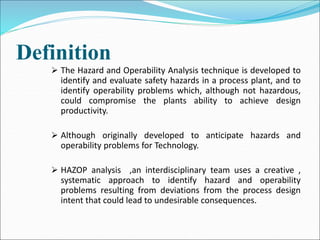
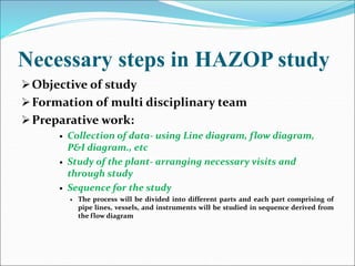
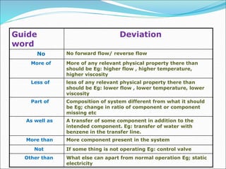
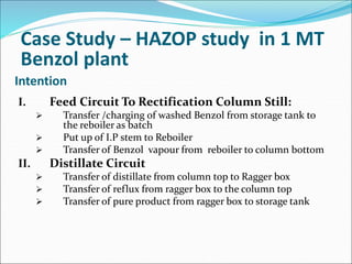
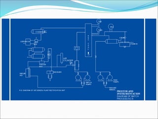
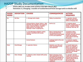
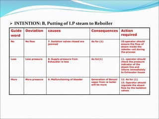
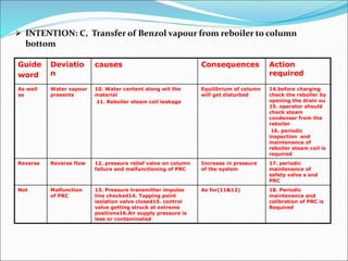
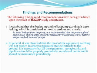
Software and Systems Engineering Standards: Verification and Validation of Sy...
Hazard operability study - in Industires and plant
1.
2. Definition
The Hazard and Operability Analysis technique is developed to
identify and evaluate safety hazards in a process plant, and to
identify operability problems which, although not hazardous,
could compromise the plants ability to achieve design
productivity.
Although originally developed to anticipate hazards and
operability problems for Technology.
HAZOP analysis ,an interdisciplinary team uses a creative ,
systematic approach to identify hazard and operability
problems resulting from deviations from the process design
intent that could lead to undesirable consequences.
3. Necessary steps in HAZOP study
Objective of study
Formation of multi disciplinary team
Preparative work:
Collection of data- using Line diagram, flow diagram,
P&I diagram., etc
Study of the plant- arranging necessary visits and
through study
Sequence for the study
The process will be divided into different parts and each part comprising of
pipe lines, vessels, and instruments will be studied in sequence derived from
the flow diagram
4. • Meetings of the examination
• Examinations by applying the guide words
• Record the results arrived
5. Guide
word
Deviation
No No forward flow/ reverse flow
More of More of any relevant physical property there than
should be Eg: higher flow , higher temperature,
higher viscosity
Less of less of any relevant physical property there than
should be Eg: lower flow , lower temperature, lower
viscosity
Part of Composition of system different from what it should
be Eg; change in ratio of component or component
missing etc
As well as A transfer of some component in addition to the
intended component. Eg: transfer of water with
benzene in the transfer line.
More than More component present in the system
Not If some thing is not operating Eg: control valve
Other than What else can apart from normal operation Eg; static
electricity
6. Intention
I. Feed Circuit To Rectification Column Still:
Transfer /charging of washed Benzol from storage tank to
the reboiler as batch
Put up of I.P stem to Reboiler
Transfer of Benzol vapour from reboiler to column bottom
II. Distillate Circuit
Transfer of distillate from column top to Ragger box
Transfer of reflux from ragger box to the column top
Transfer of pure product from ragger box to storage tank
Case Study – HAZOP study in 1 MT
Benzol plant
7.
8.
9. HAZOP Study Documentation
I. FEED CIRCUIT TO RECTIFICATION COLUMN (Batch 4&5)
Intention: A, Charging / transfer of washed benzol from storage tank to reboiler still
GUIDE
WORD
DEVIATION CAUSES CONSEQUENCES ACTION
REQUIRED
No No flow 1. storage tank empty Delay in production 1. operator should
check the tank level
before charging still
2.Pump failure ,Power failure , Gap
between the impeller and casing is
more , Bearing failure, impeller
blade bend or corroded and
improper motor coupling etc.,
As for (1) 2. Institute plant
periodic maintenance of
motor, impeller blade,
coupling, bearing, etc
3. Line blockage isolation valves
closed or jammed with pump
running
Rise in temperature of
the liquid inside the
casing of the pump leads
to fire and explosion
3.Install no flow
interlock for feed
pump4. operator should
check the isolation
valve before starting
the pump
4.Line fracture Leakage lead to fire and
Explosion
5. Institute regular
inspection of transfer
line
More OverChange 5. operator failure Reboiler over fills and
drain out leads to fire
and explosion
6. Install high level
alarm on re boiler 7.
Drain out safely the
excess liquid to the
required level8. check&
maintain the Gauge
glass level
More Over change 6. Delivery valve closed with pump
running
Batch charging pump
will subjected to churn
of liquid and leakage fro
the pump gland seal or
flange lead to fire and
explosion
8. operator should
check the valve before
starting the pump 9.
replace gland seal of
the pump with
Mechanical Seal
10. INTENTION: B, Putting of I.P steam to Reboiler
Guide
word
Deviation causes Consequences Action
required
No No flow 7. Isolation valves closed are
jammed
As for (1) 10.operator should
ensure the flow of
steam inside the
reboiler coil during
the process
Less Less pressure 8. Supply pressure from
Exhauster is less
As for(1) 11. operator should
check the pressure
indicator of the
steam line and
inform immediately
to Exhauster house
More More pressure 9. Malfunctioning of bleeder Generation of Benzol
vapor from re boiler
will be more
12. As for (1)
13. Operator should
regulate the steam
flow by the isolation
valves
11. INTENTION: C, Transfer of Benzol vapour from reboiler to column
bottom
Guide
word
Deviatio
n
causes Consequences Action
required
As well
as
Water vapour
presents
10. Water content along wit the
material
11. Reboiler steam coil leakage
Equilibrium of column
will get disturbed
14.before charging
check the reboiler by
opening the drain ou
15. operator should
check steam
condenser from the
reboiler
16. periodic
inspection and
maintenance of
reboiler steam coil is
required
Reverse Reverse flow 12. pressure relief valve on column
failure and malfunctioning of PRC
Increase in pressure
of the system
17. periodic
maintenance of
safety valve s and
PRC
Not Malfunction
of PRC
13. Pressure transmitter impulse
line chocked14. Tapping point
isolation valve closed15. control
valve getting struck at extreme
positions16.Air supply pressure is
less or contaminated
As for(11&12) 18. Periodic
maintenance and
calibration of PRC is
Required
12. II. DISTILLATE CIRCUIT FFOM RECTIFICATION COLUMN TOP.
Intention: D, Transfer of distillate form Column top to Ragger Box..
Guide
Word
Deviation Causes Consequences Action
Required
No No flow 17, As for (4), Line fracture in
between column top
and Condenser will lead
to fire and UVCE
t, As for (e).
18. Gas locking due to blockage in line
and Vent Hole.
Over flow from
separator leads to fire
and explosion.
u, Check the Vent
Hole periodically and
it should be wire
Meshed.
As well as Water vapour
presents
19, Condenser and cooler water line
leakage.
Contamination of
product.
v, Before starting the
still the condenser
and cooler line should
be checked.
No No flow of
water in
condenser.
20, Valves are closed or jammed or no
water form Header.
More escaper of
Uncondensed vapour
through Vent Hole
leads to fire and UVCE.
w, Ensure flow of
water before starting
the still.
x, Install No Flow
Alarm in Condenser
and Cooler water line.
No flow of
water in cooler.
31. As for (20) Gas locking in line
result in over flow of
material from separator
leads to fire and
explosion.
y, Install high level
alarm on separator.
13. Intention: E, Transfer of distillate form Ragger Box to the column top as
Reflux.
Guide
Word
Deviation Causes Consequences Action Required
No No flow 22. No material in Reflux Pot Delay in production Z, Start the Reflux
pump only when
the distillate comes
to Reflux Pot.
23. As for (3). As for (3) aa. Install no flow
meter Interlock for
the Reflux pump.
24. As for (2). As for (11) bb, As for (b).
25..As for (4). Lead to fire and
explosion.
cc, Institute regular
patrolling an
inspection of
transfer line.
Not LRC
malfunctioni
ng
As for (13,14,15& 16) Reflux pot overfills dd, Install High
Level Alarm on
Reflux Pot.ee,
Periodic
maintenance and
calibration of LRC is
required.
14. Intention: F, Transfer of distillate form Ragger Box to the storage tank.
Guid
e
word
Deviatio
n
Causes Consequences Action
required
No No flow 26. as for (3) Receiver over fills ff, Operator should
ensure the valves are
opened and there is
flow into the storage
tank.
27.as for (4) Lead to fire and
explosion.
gg, As for (e).
More More
temperature
28, inefficiency of cooler. Gas locking in Pipe ii, ensure and
maintain the cooling
water temperature of
the cooler
Over charge 29,opoerator failure Over flow of materials
from storage tank leads
explosion
jj, Install high level
alarm on storage tank
Other
than
Static
electricity
30, not electrically grounded.
31. escape of material through cracks of
flange joints.
Ignition of vapour leads
to fire and explosion.
kk, ensure the proper
earthing to all the
equipment, pipelines
and storage tanks.
ll, ensure the
integrity of joints and
earthing continuity
across flange joints.
15. Findings and Recommendations
The following findings and recommendations have been given based
upon the result of HAZOP study undertaken.
1. It was found that the feed pump and reflux pump gland seals were
leaking, which is considered as most hazardous and unsafe.
To avoid leakage from the pump, it is recommended that the present gland
packing seal of the pumps should be replaced by mechanical seal or better b
magnetically driven seal pumps.
2. In general, it was observed that the most of the equipment earthing
was not proper. In order to generated static electricity to the
ground, it is necessary that all the equipment, storage tanks and
pipelines should be properly grounded at number of points and it
should be maintained periodically.
16. 3. The vents, which are provided are not screened with fine wire
mesh, hence it is recommended to screened the vents will fine
wire mesh. Otherwise, the content of a tank or still will get
ignited in of a flash back from escaping vapors.
4. The instrument control systems must be maintained in good
working conditions. Periodic maintenance of such systems is
necessary to prevent an risk arising due to the deviations of such
systems (refer HAZOP study documentation.)
5. Regular inspection should be varied out to ensure the integrity of
flange joints. Use of unreinforced joints should be avoided.