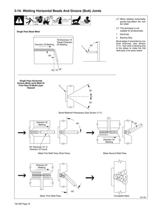
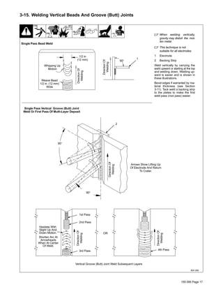
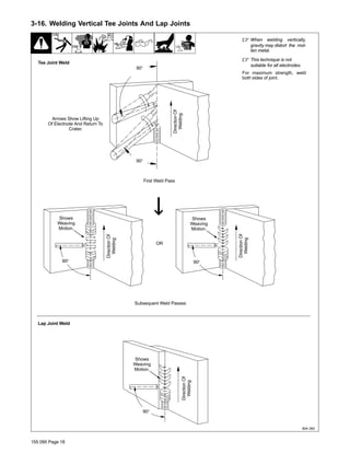
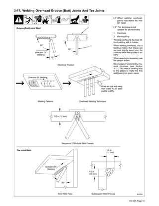
SlideShare a Scribd company logo
Processes
Stick (SMAW) Welding
155 095 E
2013−07
Guidelines For
Shielded Metal Arc
Welding (SMAW)
Visit our website at
www.MillerWelds.com
TABLE OF CONTENTS
SECTION 1 − SAFETY PRECAUTIONS - READ BEFORE USING 1. . . . . . . . . . . . . . . . . . . . . . . . . . . . . . . . . . .
1-1. Symbol Usage 1. . . . . . . . . . . . . . . . . . . . . . . . . . . . . . . . . . . . . . . . . . . . . . . . . . . . . . . . . . . . . . . . . . . . . . . .
1-2. Arc Welding Hazards 1. . . . . . . . . . . . . . . . . . . . . . . . . . . . . . . . . . . . . . . . . . . . . . . . . . . . . . . . . . . . . . . . . .
1-3. Additional Symbols For Installation, Operation, And Maintenance 3. . . . . . . . . . . . . . . . . . . . . . . . . . . . .
1-4. California Proposition 65 Warnings 4. . . . . . . . . . . . . . . . . . . . . . . . . . . . . . . . . . . . . . . . . . . . . . . . . . . . . . .
1-5. Principal Safety Standards 4. . . . . . . . . . . . . . . . . . . . . . . . . . . . . . . . . . . . . . . . . . . . . . . . . . . . . . . . . . . . .
1-6. EMF Information 4. . . . . . . . . . . . . . . . . . . . . . . . . . . . . . . . . . . . . . . . . . . . . . . . . . . . . . . . . . . . . . . . . . . . . .
SECTION 2 − PRINCIPLES OF SHIELDED METAL ARC WELDING (SMAW) 5. . . . . . . . . . . . . . . . . . . . . . . . .
SECTION 3 − SHIELDED METAL ARC WELDING (SMAW)PROCEDURE 6. . . . . . . . . . . . . . . . . . . . . . . . . . . .
3-1. Typical Stick Welding Set-Up 6. . . . . . . . . . . . . . . . . . . . . . . . . . . . . . . . . . . . . . . . . . . . . . . . . . . . . . . . . . .
3-2. Electrode And Amperage Selection Chart 7. . . . . . . . . . . . . . . . . . . . . . . . . . . . . . . . . . . . . . . . . . . . . . . . .
3-3. Striking An Arc − Scratch Start Technique 8. . . . . . . . . . . . . . . . . . . . . . . . . . . . . . . . . . . . . . . . . . . . . . . . .
3-4. Striking An Arc − Tapping Technique 8. . . . . . . . . . . . . . . . . . . . . . . . . . . . . . . . . . . . . . . . . . . . . . . . . . . . .
3-5. Positioning Electrode Holder 9. . . . . . . . . . . . . . . . . . . . . . . . . . . . . . . . . . . . . . . . . . . . . . . . . . . . . . . . . . . .
3-6. Electrode Movement During Welding 10. . . . . . . . . . . . . . . . . . . . . . . . . . . . . . . . . . . . . . . . . . . . . . . . . . . . .
3-7. Conditions That Affect Weld Bead Shape 11. . . . . . . . . . . . . . . . . . . . . . . . . . . . . . . . . . . . . . . . . . . . . . . . .
3-8. Poor Weld Bead Characteristics 12. . . . . . . . . . . . . . . . . . . . . . . . . . . . . . . . . . . . . . . . . . . . . . . . . . . . . . . . .
3-9. Good Weld Bead Characteristics 12. . . . . . . . . . . . . . . . . . . . . . . . . . . . . . . . . . . . . . . . . . . . . . . . . . . . . . . .
3-10. Typical Weld Joints 13. . . . . . . . . . . . . . . . . . . . . . . . . . . . . . . . . . . . . . . . . . . . . . . . . . . . . . . . . . . . . . . . . . . .
3-11. Welding Groove (Butt) Joints 14. . . . . . . . . . . . . . . . . . . . . . . . . . . . . . . . . . . . . . . . . . . . . . . . . . . . . . . . . . . .
3-12. Welding Tee Joints 15. . . . . . . . . . . . . . . . . . . . . . . . . . . . . . . . . . . . . . . . . . . . . . . . . . . . . . . . . . . . . . . . . . . .
3-13. Welding Lap Joints 15. . . . . . . . . . . . . . . . . . . . . . . . . . . . . . . . . . . . . . . . . . . . . . . . . . . . . . . . . . . . . . . . . . . .
3-14. Welding Horizontal Beads And Groove (Butt) Joints 16. . . . . . . . . . . . . . . . . . . . . . . . . . . . . . . . . . . . . . . .
3-15. Welding Vertical Beads And Groove (Butt) Joints 17. . . . . . . . . . . . . . . . . . . . . . . . . . . . . . . . . . . . . . . . . . .
3-16. Welding Vertical Tee Joints And Lap Joints 18. . . . . . . . . . . . . . . . . . . . . . . . . . . . . . . . . . . . . . . . . . . . . . . .
3-17. Welding Overhead Groove (Butt) Joints And Tee Joints 19. . . . . . . . . . . . . . . . . . . . . . . . . . . . . . . . . . . . .
3-18. Weld Test 20. . . . . . . . . . . . . . . . . . . . . . . . . . . . . . . . . . . . . . . . . . . . . . . . . . . . . . . . . . . . . . . . . . . . . . . . . . . .
SECTION 4 − WELDING TROUBLESHOOTING 20. . . . . . . . . . . . . . . . . . . . . . . . . . . . . . . . . . . . . . . . . . . . . . . . . .
4-1. Porosity 20. . . . . . . . . . . . . . . . . . . . . . . . . . . . . . . . . . . . . . . . . . . . . . . . . . . . . . . . . . . . . . . . . . . . . . . . . . . . .
4-2. Excessive Spatter 21. . . . . . . . . . . . . . . . . . . . . . . . . . . . . . . . . . . . . . . . . . . . . . . . . . . . . . . . . . . . . . . . . . . . .
4-3. Incomplete Fusion 21. . . . . . . . . . . . . . . . . . . . . . . . . . . . . . . . . . . . . . . . . . . . . . . . . . . . . . . . . . . . . . . . . . . .
4-4. Lack Of Penetration 21. . . . . . . . . . . . . . . . . . . . . . . . . . . . . . . . . . . . . . . . . . . . . . . . . . . . . . . . . . . . . . . . . . .
4-5. Excessive Penetration 22. . . . . . . . . . . . . . . . . . . . . . . . . . . . . . . . . . . . . . . . . . . . . . . . . . . . . . . . . . . . . . . . .
4-6. Burn-Through 22. . . . . . . . . . . . . . . . . . . . . . . . . . . . . . . . . . . . . . . . . . . . . . . . . . . . . . . . . . . . . . . . . . . . . . . .
4-7. Waviness Of Bead 22. . . . . . . . . . . . . . . . . . . . . . . . . . . . . . . . . . . . . . . . . . . . . . . . . . . . . . . . . . . . . . . . . . . .
4-8. Distortion 22. . . . . . . . . . . . . . . . . . . . . . . . . . . . . . . . . . . . . . . . . . . . . . . . . . . . . . . . . . . . . . . . . . . . . . . . . . . .
155 095 Page 1
SECTION 1 − SAFETY PRECAUTIONS - READ BEFORE USING
som 2011−10
7
Protect yourself and others from injury — read, follow, and save these important safety precautions and operating instructions.
1-1. Symbol Usage
DANGER! − Indicates a hazardous situation which, if
not avoided, will result in death or serious injury. The
possible hazards are shown in the adjoining symbols
or explained in the text.
Indicates a hazardous situation which, if not avoided,
could result in death or serious injury. The possible
hazards are shown in the adjoining symbols or ex-
plained in the text.
NOTICE − Indicates statements not related to personal injury.
. Indicates special instructions.
This group of symbols means Warning! Watch Out! ELECTRIC
SHOCK, MOVING PARTS, and HOT PARTS hazards. Consult sym-
bols and related instructions below for necessary actions to avoid the
hazards.
1-2. Arc Welding Hazards
The symbols shown below are used throughout this manual
to call attention to and identify possible hazards. When you
see the symbol, watch out, and follow the related instructions
to avoid the hazard. The safety information given below is
only a summary of the more complete safety information
found in the Safety Standards listed in Section 1-5. Read and
follow all Safety Standards.
Only qualified persons should install, operate, maintain, and
repair this unit.
During operation, keep everybody, especially children, away.
ELECTRIC SHOCK can kill.
Touching live electrical parts can cause fatal shocks
or severe burns. The electrode and work circuit is
electrically live whenever the output is on. The input
power circuit and machine internal circuits are also
live when power is on. In semiautomatic or automatic
wire welding, the wire, wire reel, drive roll housing,
and all metal parts touching the welding wire are
electrically live. Incorrectly installed or improperly
grounded equipment is a hazard.
D Do not touch live electrical parts.
D Wear dry, hole-free insulating gloves and body protection.
D Insulate yourself from work and ground using dry insulating mats
or covers big enough to prevent any physical contact with the work
or ground.
D Do not use AC output in damp areas, if movement is confined, or if
there is a danger of falling.
D Use AC output ONLY if required for the welding process.
D If AC output is required, use remote output control if present on
unit.
D Additionalsafety precautions are required when any of the follow-
ing electrically hazardous conditions are present: in damp
locations or while wearing wet clothing; on metal structures such
as floors, gratings, or scaffolds; when in cramped positions such
as sitting, kneeling, or lying; or when there is a high risk of unavoid-
able or accidental contact with the workpiece or ground. For these
conditions, use the following equipment in order presented: 1) a
semiautomaticDC constant voltage (wire) welder, 2) a DC manual
(stick) welder, or 3) an AC welder with reduced open-circuit volt-
age. In most situations, use of a DC, constant voltage wire welder
is recommended. And, do not work alone!
D Disconnect input power or stop engine before installing or
servicing this equipment. Lockout/tagout input power according to
OSHA 29 CFR 1910.147 (see Safety Standards).
D Properly install, ground, and operate this equipment according to
its Owner’s Manual and national, state, and local codes.
D Always verify the supply ground − check and be sure that input
power cord ground wire is properly connected to ground terminal in
disconnect box or that cord plug is connected to a properly
grounded receptacle outlet.
D When making input connections, attach proper grounding conduc-
tor first − double-check connections.
D Keep cords dry, free of oil and grease, and protected from hot metal
and sparks.
D Frequently inspect input power cord for damage or bare wiring −
replace cord immediately if damaged − bare wiring can kill.
D Turn off all equipment when not in use.
D Do not use worn, damaged, undersized, or poorly spliced cables.
D Do not drape cables over your body.
D If earth grounding of the workpiece is required, ground it directly
with a separate cable.
D Do not touch electrode if you are in contact with the work, ground,
or another electrode from a different machine.
D Do not touch electrode holders connected to two welding ma-
chines at the same time since double open-circuit voltage will be
present.
D Use only well-maintained equipment. Repair or replace damaged
parts at once. Maintain unit according to manual.
D Wear a safety harness if working above floor level.
D Keep all panels and covers securely in place.
D Clamp work cable with good metal-to-metal contact to workpiece
or worktable as near the weld as practical.
D Insulate work clamp when not connected to workpiece to prevent
contact with any metal object.
D Do not connect more than one electrode or work cable to any
single weld output terminal. Disconnect cable for process not in
use.
SIGNIFICANT DC VOLTAGE exists in inverter weld-
ing power sources AFTER removal of input power.
D Turn Off inverter, disconnect input power, and discharge input
capacitors according to instructions in Maintenance Section
before touching any parts.
HOT PARTS can burn.
D Do not touch hot parts bare handed.
D Allow cooling period before working on equip-
ment.
D To handle hot parts, use proper tools and/or
wear heavy, insulated welding gloves and
clothing to prevent burns.
155 095 Page 2
Welding produces fumes and gases. Breathing
these fumes and gases can be hazardous to your
health.
FUMES AND GASES can be hazardous.
D Keep your head out of the fumes. Do not breathe the fumes.
D If inside, ventilate the area and/or use local forced ventilation at the
arc to remove welding fumes and gases.
D If ventilation is poor, wear an approved air-supplied respirator.
D Read and understand the Material Safety Data Sheets (MSDSs)
and the manufacturer’s instructions for metals, consumables,
coatings, cleaners, and degreasers.
D Work in a confined space only if it is well ventilated, or while
wearing an air-supplied respirator. Always have a trained watch-
person nearby. Welding fumes and gases can displace air and
lower the oxygen level causing injury or death. Be sure the breath-
ing air is safe.
D Do not weld in locations near degreasing, cleaning, or spraying op-
erations. The heat and rays of the arc can react with vapors to form
highly toxic and irritating gases.
D Do not weld on coated metals, such as galvanized, lead, or
cadmium plated steel, unless the coating is removed from the weld
area, the area is well ventilated, and while wearing an air-supplied
respirator. The coatings and any metals containing these elements
can give off toxic fumes if welded.
Arc rays from the welding process produce intense
visible and invisible (ultraviolet and infrared) rays
that can burn eyes and skin. Sparks fly off from the
weld.
D Wear an approved welding helmet fitted with a proper shade of
filter lenses to protect your face and eyes from arc rays and
sparks when welding or watching (see ANSI Z49.1 and Z87.1
listed in Safety Standards).
D Wear approved safety glasses with side shields under your
helmet.
D Use protective screens or barriers to protect others from flash,
glare and sparks; warn others not to watch the arc.
D Wear protective clothing made from durable, flame-resistant
material (leather, heavy cotton, or wool) and foot protection.
ARC RAYS can burn eyes and skin.
Welding on closed containers, such as tanks,
drums, or pipes, can cause them to blow up. Sparks
can fly off from the welding arc. The flying sparks, hot
workpiece, and hot equipment can cause fires and
burns. Accidental contact of electrode to metal objects can cause
sparks, explosion, overheating, or fire. Check and be sure the area is
safe before doing any welding.
WELDING can cause fire or explosion.
D Remove all flammables within 35 ft (10.7 m) of the welding arc. If
this is not possible, tightly cover them with approved covers.
D Do not weld where flying sparks can strike flammable material.
D Protect yourself and others from flying sparks and hot metal.
D Be alert that welding sparks and hot materials from welding can
easily go through small cracks and openings to adjacent areas.
D Watch for fire, and keep a fire extinguisher nearby.
D Be aware that welding on a ceiling, floor, bulkhead, or partition can
cause fire on the hidden side.
D Do not weld on containers that have held combustibles, or on
closed containers such as tanks, drums, or pipes unless they are
properly prepared according to AWS F4.1 and AWS A6.0 (see
Safety Standards).
D Do not weld where the atmosphere may contain flammable dust,
gas, or liquid vapors (such as gasoline).
D Connect work cable to the work as close to the welding area as
practical to prevent welding current from traveling long, possibly
unknown paths and causing electric shock, sparks, and fire
hazards.
D Do not use welder to thaw frozen pipes.
D Remove stick electrode from holder or cut off welding wire at
contact tip when not in use.
D Wear oil-free protective garments such as leather gloves, heavy
shirt, cuffless trousers, high shoes, and a cap.
D Remove any combustibles, such as a butane lighter or matches,
from your person before doing any welding.
D After completion of work, inspect area to ensure it is free of sparks,
glowing embers, and flames.
D Use only correct fuses or circuit breakers. Do not oversize or by-
pass them.
D Follow requirements in OSHA 1910.252 (a) (2) (iv) and NFPA 51B
for hot work and have a fire watcher and extinguisher nearby.
FLYING METAL or DIRT can injure eyes.
D Welding, chipping, wire brushing, and grinding
cause sparks and flying metal. As welds cool,
they can throw off slag.
D Wear approved safety glasses with side
shields even under your welding helmet.
BUILDUP OF GAS can injure or kill.
D Shut off compressed gas supply when not in use.
D Always ventilate confined spaces or use
approved air-supplied respirator.
ELECTRIC AND MAGNETIC FIELDS (EMF)
can affect Implanted Medical Devices.
D Wearers of Pacemakers and other Implanted
Medical Devices should keep away.
D ImplantedMedical Device wearers should consult their doctor
and the device manufacturer before going near arc welding, spot
welding, gouging, plasma arc cutting, or induction heating
operations.
NOISE can damage hearing.
Noise from some processes or equipment can
damage hearing.
D Wear approved ear protection if noise level is
high.
Compressed gas cylinders contain gas under high
pressure. If damaged, a cylinder can explode. Since
gas cylinders are normally part of the welding
process, be sure to treat them carefully.
CYLINDERS can explode if damaged.
D Protect compressed gas cylinders from excessive heat, mechani-
cal shocks, physical damage, slag, open flames, sparks, and arcs.
D Install cylinders in an upright position by securing to a stationary
support or cylinder rack to prevent falling or tipping.
D Keep cylinders away from any welding or other electrical circuits.
D Never drape a welding torch over a gas cylinder.
D Never allow a welding electrode to touch any cylinder.
D Never weld on a pressurized cylinder − explosion will result.
D Use only correct compressed gas cylinders, regulators, hoses,
and fittings designed for the specific application; maintain them
and associated parts in good condition.
D Turn face away from valve outlet when opening cylinder valve.
D Keep protective cap in place over valve except when cylinder is in
use or connected for use.
D Use the right equipment, correct procedures, and sufficient num-
ber of persons to lift and move cylinders.
D Read and follow instructions on compressed gas cylinders,
associated equipment, and Compressed Gas Association (CGA)
publication P-1 listed in Safety Standards.
155 095 Page 3
1-3. Additional Symbols For Installation, Operation, And Maintenance
FIRE OR EXPLOSION hazard.
D Do not install or place unit on, over, or near
combustible surfaces.
D Do not install unit near flammables.
D Do not overload building wiring − be sure power supply system is
properly sized, rated, and protected to handle this unit.
FALLING EQUIPMENT can injure.
D Use lifting eye to lift unit only, NOT running
gear, gas cylinders, or any other accessories.
D Use equipment of adequate capacity to lift and
support unit.
D If using lift forks to move unit, be sure forks are long enough to
extend beyond opposite side of unit.
D Keep equipment (cables and cords) away from moving vehicles
when working from an aerial location.
D Follow the guidelines in the Applications Manual for the Revised
NIOSH Lifting Equation (Publication No. 94−110) when manu-
ally lifting heavy parts or equipment.
OVERUSE can cause OVERHEATING
D Allow cooling period; follow rated duty cycle.
D Reduce current or reduce duty cycle before
starting to weld again.
D Do not block or filter airflow to unit.
FLYING SPARKS can injure.
D Wear a face shield to protect eyes and face.
D Shape tungsten electrode only on grinder with
proper guards in a safe location wearing proper
face, hand, and body protection.
D Sparks can cause fires — keep flammables away.
STATIC (ESD) can damage PC boards.
D Put on grounded wrist strap BEFORE handling
boards or parts.
D Use proper static-proof bags and boxes to
store, move, or ship PC boards.
MOVING PARTS can injure.
D Keep away from moving parts.
D Keep away from pinch points such as drive
rolls.
WELDING WIRE can injure.
D Do not press gun trigger until instructed to do
so.
D Do not point gun toward any part of the body,
other people, or any metal when threading
welding wire.
BATTERY EXPLOSION can injure.
D Do not use welder to charge batteries or jump
start vehicles unless it has a battery charging
feature designed for this purpose.
MOVING PARTS can injure.
D Keep away from moving parts such as fans.
D Keep all doors, panels, covers, and guards
closed and securely in place.
D Have only qualified persons remove doors, panels, covers, or
guards for maintenance and troubleshooting as necessary.
D Reinstall doors, panels, covers, or guards when maintenance is
finished and before reconnecting input power.
READ INSTRUCTIONS.
D Read and follow all labels and the Owner’s
Manual carefully before installing, operating, or
servicing unit. Read the safety information at
the beginning of the manual and in each
section.
D Use only genuine replacement parts from the manufacturer.
D Perform maintenance and service according to the Owner’s
Manuals, industry standards, and national, state, and local
codes.
H.F. RADIATION can cause interference.
D High-frequency (H.F.) can interfere with radio
navigation, safety services, computers, and
communicationsequipment.
D Have only qualified persons familiar with
electronic equipment perform this installation.
D The user is responsible for having a qualified electrician prompt-
ly correct any interference problem resulting from the installa-
tion.
D If notified by the FCC about interference, stop using the
equipmentat once.
D Have the installation regularly checked and maintained.
D Keep high-frequency source doors and panels tightly shut, keep
spark gaps at correct setting, and use grounding and shielding to
minimize the possibility of interference.
ARC WELDING can cause interference.
D Electromagnetic energy can interfere with
sensitive electronic equipment such as
computers and computer-driven equipment
such as robots.
D Be sure all equipment in the welding area is
electromagneticallycompatible.
D To reduce possible interference, keep weld cables as short as
possible, close together, and down low, such as on the floor.
D Locate welding operation 100 meters from any sensitive elec-
tronic equipment.
D Be sure this welding machine is installed and grounded
according to this manual.
D If interference still occurs, the user must take extra measures
such as moving the welding machine, using shielded cables,
using line filters, or shielding the work area.
155 095 Page 4
1-4. California Proposition 65 Warnings
Welding or cutting equipment produces fumes or gases
which contain chemicals known to the State of California to
cause birth defects and, in some cases, cancer. (California
Health & Safety Code Section 25249.5 et seq.)
This product contains chemicals, including lead, known to
the state of California to cause cancer, birth defects, or other
reproductive harm. Wash hands after use.
1-5. Principal Safety Standards
Safety in Welding, Cutting, and Allied Processes, ANSI Standard Z49.1,
is available as a free download from the American Welding Society at
http://www.aws.org or purchased from Global Engineering Documents
(phone: 1-877-413-5184, website: www.global.ihs.com).
Safe Practices for the Preparation of Containers and Piping for Welding
and Cutting, American Welding Society Standard AWS F4.1, from Glob-
al Engineering Documents (phone: 1-877-413-5184, website:
www.global.ihs.com).
Safe Practices for Welding and Cutting Containers that have Held Com-
bustibles, American Welding Society Standard AWS A6.0, from Global
EngineeringDocuments (phone: 1-877-413-5184,
website: www.global.ihs.com).
National Electrical Code, NFPA Standard 70, from National Fire Protec-
tion Association, Quincy, MA 02269 (phone: 1-800-344-3555, website:
www.nfpa.org and www. sparky.org).
Safe Handling of Compressed Gases in Cylinders, CGA Pamphlet P-1,
from Compressed Gas Association, 14501 George Carter Way, Suite
103, Chantilly, VA 20151 (phone: 703-788-2700, website:www.cga-
net.com).
Safety in Welding, Cutting, and Allied Processes, CSA Standard
W117.2, from Canadian Standards Association, Standards Sales, 5060
Spectrum Way, Suite 100, Ontario, Canada L4W 5NS (phone:
800-463-6727, website: www.csa-international.org).
Safe Practice For Occupational And Educational Eye And Face Protec-
tion, ANSI Standard Z87.1, from American National Standards Institute,
25 West 43rd Street, New York, NY 10036 (phone: 212-642-4900, web-
site: www.ansi.org).
Standard for Fire Prevention During Welding, Cutting, and Other Hot
Work, NFPA Standard 51B, from National Fire Protection Association,
Quincy, MA 02269 (phone: 1-800-344-3555, website: www.nfpa.org.
OSHA, Occupational Safety and Health Standards for General Indus-
try, Title 29, Code of Federal Regulations (CFR), Part 1910, Subpart Q,
and Part 1926, Subpart J, from U.S. Government Printing Office, Super-
intendentof Documents, P.O. Box 371954, Pittsburgh, PA 15250-7954
(phone: 1-866-512-1800) (there are 10 OSHA Regional Offices—
phone for Region 5, Chicago, is 312-353-2220, website:
www.osha.gov).
Applications Manual for the Revised NIOSH Lifting Equation, The Na-
tional Institute for Occupational Safety and Health (NIOSH), 1600
Clifton Rd, Atlanta, GA 30333 (phone: 1-800-232-4636, website:
www.cdc.gov/NIOSH).
1-6. EMF Information
Electric current flowing through any conductor causes localized electric
and magnetic fields (EMF). Welding current creates an EMF field
around the welding circuit and welding equipment. EMF fields may inter-
fere with some medical implants, e.g. pacemakers. Protective
measures for persons wearing medical implants have to be taken. For
example, restrict access for passers−by or conduct individual risk as-
sessment for welders. All welders should use the following procedures
in order to minimize exposure to EMF fields from the welding circuit:
1. Keep cables close together by twisting or taping them, or using a
cable cover.
2. Do not place your body between welding cables. Arrange cables
to one side and away from the operator.
3. Do not coil or drape cables around your body.
4. Keep head and trunk as far away from the equipment in the
welding circuit as possible.
5. Connect work clamp to workpiece as close to the weld as
possible.
6. Do not work next to, sit or lean on the welding power source.
7. Do not weld whilst carrying the welding power source or wire
feeder.
About Implanted Medical Devices:
ImplantedMedical Device wearers should consult their doctor and the
device manufacturer before performing or going near arc welding, spot
welding, gouging, plasma arc cutting, or induction heating operations.
If cleared by your doctor, then following the above procedures is recom-
mended.
155 095 Page 5
SECTION 2 − PRINCIPLES OF SHIELDED METAL ARC
WELDING (SMAW)
Shielded Metal Arc Welding (SMAW) or Stick welding is a process which melts and joins metals by heating them with
an arc between a coated metal electrode and the workpiece. The electrode outer coating, called flux, assists in creat-
ing the arc and provides the shielding gas and slag covering to protect the weld from contamination. The electrode
core provides most of the weld filler metal.
When the electrode is moved along the workpiece at the correct speed the metal deposits in a uniform layer called
a bead.
The Stick welding power source provides constant current (CC) and may be either alternating current (AC) or direct
current (DC), depending on the electrode being used. The best welding characteristics are usually obtained using DC
power sources.
The power in a welding circuit is measured in voltage and current. The voltage (Volts) is governed by the arc length
between the electrode and the workpiece and is influenced by electrode diameter. Current is a more practical measure
of the power in a weld circuit and is measured in amperes (Amps).
The amperage needed to weld depends on electrode diameter, the size and thickness of the pieces to be welded,
and the position of the welding. Thin metals require less current than thick metals, and a small electrode requires less
amperage than a large one.
It is preferable to weld on work in the flat or horizontal position. However, when forced to weld in vertical or overhead
positions it is helpful to reduce the amperage from that used when welding horizontally. Best welding results are
achieved by maintaining a short arc, moving the electrode at a uniform speed, and feeding the electrode downward
at a constant speed as it melts.
More specific information on the Stick welding procedure is provided in the following sections.
1 Stick Welding Power Source
− Constant Current (CC), AC
Or DC
2 Insulated Electrode Holder
3 Workpiece
4 Work Clamp
Ref. 157 858
1
2
3 4
155 095 Page 6
SECTION 3 − SHIELDED METAL ARC WELDING (SMAW)
PROCEDURE
3-1. Typical Stick Welding Set-Up
! Welding current starts as soon as
electrode touches the workpiece.
! Weld current can damage elec-
tronic parts in vehicles. Discon-
nect both battery cables before
welding on a vehicle. Place work
clamp as close to the weld as
possible.
. Always wear appropriate personal
protective clothing.
1 Workpiece
Make sure workpiece is clean before
welding.
2 Work Clamp
Place as close to the weld as possible.
3 Electrode
Before striking an arc, insert an electrode
in the electrode holder. A small diameter
electrode requires less current than a
large one. Follow recommendations of
the electrode manufacturer when setting
weld amperage (see Section 3-2).
4 Insulated Electrode Holder
5 Electrode Holder Position
6 Arc Length
Arc length is the distance from the elec-
trode to the workpiece. A short arc with
correct amperage will give a sharp,
crackling sound. Correct arc length is re-
lated to electrode diameter. Examine the
weld bead to determine if the arc length
is correct.
Arc length for 1/16 and 3/32 in. diameter
electrodes should be about 1/16 in. (1.6
mm); arc length for 1/8 and 5/32 in. elec-
trodes should be about 1/8 in. (3 mm).
7 Slag
Use a chipping hammer and wire brush to
remove slag. Remove slag and check
weld bead before making another weld
pass.
151 593
1
4
3
5
2
Tools Needed:
7
6
155 095 Page 7
3-2. Electrode And Amperage Selection Chart
Ref. S-087 985-A
3/32
1/8
5/32
3/16
7/32
1/4
1/16
5/64
3/32
1/8
5/32
3/16
7/32
1/4
3/32
1/8
5/32
3/16
7/32
1/4
3/32
1/8
5/32
3/16
7/32
1/4
3/32
1/8
5/32
3/16
7/32
1/4
3/32
1/8
5/32
3/16
3/32
1/8
5/32
6010
&
6011
6013
7014
7018
7024
Ni-Cl
308L
50
100
150
200
250
300
350
400
450
ELECTRODE
DC*
AC
POSITION
PENETRATION
USAGE
MIN. PREP, ROUGH
HIGH SPATTER
GENERAL
SMOOTH, EASY,
FAST
LOW HYDROGEN,
STRONG
SMOOTH, EASY,
FASTER
CAST IRON
STAINLESS
DEEP
DEEP
LOW
MED
LOW
LOW
LOW
ALL
ALL
ALL
ALL
ALL
FLAT
HORIZ
FILLET
ALL
ALL
EP
EP
EP,EN
EP,EN
EP
EP,EN
EP
EP
6010
6011
6013
7014
7018
7024
NI-CL
308L
*EP = ELECTRODE POSITIVE (REVERSE POLARITY)
EN = ELECTRODE NEGATIVE (STRAIGHT POLARITY)
ELECTRODE
AMPERAGE
RANGE
DIAMETER
MED
155 095 Page 8
3-3. Striking An Arc − Scratch Start Technique
! Welding current starts as
soon as electrode touches the
workpiece.
. The scratch-start technique is
preferred for ac welding.
1 Electrode
2 Workpiece
3 Arc
Drag electrode across workpiece
like striking a match; immediately lift
electrode slightly after touching
work. If arc goes out, electrode was
lifted too high. If electrode sticks to
workpiece, use a quick twist to free it.
S-0049
1
2
3
3-4. Striking An Arc − Tapping Technique
S-0049
! Welding current starts as
soon as electrode touches the
workpiece.
1 Electrode
2 Workpiece
3 Arc
Bring electrode straight down to
workpiece; then lift slightly to start
arc. If arc goes out, electrode was
lifted too high. If electrode sticks to
workpiece, use a quick twist to free it.
1
3
2
155 095 Page 9
3-5. Positioning Electrode Holder
S-0660
90° 90°
10°- 30°
45°
45°
End View Of Work Angle Side View Of Electrode Angle
10°- 30°
Fillet Welds
Groove Welds
After learning to start and hold an
arc, practice running beads of weld
metal on flat plates using a full elec-
trode.
Hold the electrode nearly perpen-
dicular to the work, although tilting
it ahead (in the direction of travel)
will be helpful.
. To produce the best results,
hold a short arc, travel at a uni-
form speed, and feed the elec-
trode downward at a constant
rate as it melts.
Direction Of Welding
155 095 Page 10
3-6. Electrode Movement During Welding
. A single stringer bead is satisfac-
tory for most narrow groove weld
joints; however, for wide groove
weld joints or bridging across gaps,
a weave bead or multiple stringer
beads work better.
1 Stringer Bead − Steady Move-
ment Along Seam
2 Weave Bead − Side To Side
Movement Along Seam
3 Weave Patterns
Use weave patterns to cover a wide
area in one pass of the electrode. Limit
weave width to a maximum of 2-1/2
times diameter of electrode.
S-0054-A
1
2
3
Notes
Work like a Pro!
Pros weld and cut
safely. Read the
safety rules at
the beginning
of this manual.
155 095 Page 11
3-7. Conditions That Affect Weld Bead Shape
. Weld bead shape is affected by electrode angle, arc length, travel speed, and thickness of base metal.
S-0661
Too Slow Normal
10° - 30°
Drag
Too Short Normal Too Long
Spatter
Angle Too Small Angle Too Large
Correct Angle
Too Fast
Electrode Angle
Arc Length
Travel Speed
155 095 Page 12
3-8. Poor Weld Bead Characteristics
1 Large Spatter Deposits
2 Rough, Uneven Bead
3 Slight Crater During
Welding
4 Bad Overlap
5 Poor Penetration
S-0053-A
5
42 3
1
3-9. Good Weld Bead Characteristics
1 Fine Spatter
2 Uniform Bead
3 Moderate Crater During
Welding
4 No Overlap
5 Good Penetration Into Base
Metal
S-0052-B
1
52 3 4
155 095 Page 13
3-10. Typical Weld Joints
804 248
Vertical Position Welds Overhead Position Welds
Flat Position Welds Horizontal Position Welds
Tee Joint
Groove (Butt) Joint
Lap Joint Tee JointLap Joint
Tee JointLap Joint Tee JointLap Joint
Groove (Butt) Joint
Groove (Butt) Joint Groove (Butt) Joint
155 095 Page 14
3-11. Welding Groove (Butt) Joints
Types Of Groove (Butt) Joint Welds
1 Tack Welds
Prevent butt joint distortion by tack welding
the materials in position before final weld.
Workpiece distortion occurs when heat is
applied locally to a joint. One side of a met-
al plate will “curl” up toward the weld. Dis-
tortion will also cause the edges of a butt
joint to pull together ahead of the electrode
as the weld cools.
2 Square Groove Weld
3 Single V-Groove Weld
4 Double V-Groove Weld
Materials up to 3/16 in. (5 mm) thick can
often be welded without special prepara-
tion using the square groove weld. Howev-
er, when welding thicker materials it may
be necessary to prepare the edges (V-
groove) of butt joints to ensure good welds.
The single or double V-groove weld is good
for materials 3/16 − 3/4 in. (5-19 mm) thick.
Generally, the single V-groove is used on
materials up to 3/4 in. (19 mm) thick and
when, regardless of thickness, you can
weld from one side only. Create a 30 de-
gree bevel with oxyacetylene or plasma
cutting equipment. Remove scale from
materialafter cutting. A grinder can also be
used to prepare bevels.
Groove (Butt) Joint Training Procedure
Practice welding butt joints on 1/8 in. (4
mm) or thicker material. (Avoid thinner ma-
terials since they require greater skill.)
Separate the squared edges of the materi-
al about 1/16 in. (1.6 mm) and make a butt
weld all the way through with a 1/8 in. elec-
trode. (You may need to adjust the weld
current and travel speed to obtain the de-
sired weld.) Perform a similar exercise on
1/4 in. (6 mm) material, depositing a bead
on each side of the joint and fusing one to
the another (no bevel needed).
Practice making a single V-groove weld on
1/4 in. (6 mm) plate beveled 30°. Start with
a 1/8 in. electrode for the first bead and fin-
ish with a 5/32 in. (4 mm) electrode. Be
sure to penetrate about 1/32 in. (1 mm) be-
yond the bottom of the “V” or root. Perform
a similar exercise on thicker materials.
Generally, deposit a bead for each 1/8 in.
(3mm) of material thickness, cleaning the
joint between layers. On heavier plates, it
may be necessary to weave the top layers
to fill the groove.
After completing the practice welds, test
them as described in Section 3-18.
S-0662
30°
2
1
1/16 in.
(1.6 mm)
3 4
Root Face
155 095 Page 15
3-12. Welding Tee Joints
1 Electrode
2 Fillet Weld
Keep arc short and move at definite
rate of speed. Hold electrode as
shown to provide fusion into the
corner. Square edge of the weld
surface.
For maximum strength weld both
sides of upright section.
3 Multi-Layer Deposits
Weld a second layer when a heavi-
er fillet is needed. Use any of the
weaving patterns shown in Section
3-6. Remove slag before making
another weld pass.
45°
Or Less
S-0060 / S-0058-A / S-0061
1
2
1
3
2
3-13. Welding Lap Joints
1 Electrode
2 Single-Layer Fillet Weld
Move electrode in circular motion.
3 Multi-Layer Fillet Weld
Weld a second layer when a heavi-
er fillet is needed. Remove slag be-
fore making another weld pass.
Weld both sides of joint for maxi-
mum strength.
30°
Or Less
S-0063 / S-0064
Single-Layer Fillet Weld
Multi-Layer Fillet Weld
30°
Or Less
1
1
2
3
155 095 Page 16
3-14. Welding Horizontal Beads And Groove (Butt) Joints
. When welding horizontally,
gravity may distort the mol-
ten metal.
. This technique is not
suitable for all electrodes.
1 Electrode
2 Backing Strip
Bevel edges if warranted by ma-
terial thickness (see Section
3-11). Tack weld a backing strip
to the plates to make the first
weld pass (root pass) easier.
804 260
Direction Of
Welding
90°
2
Direction Of
Welding
Tilt Electrode 15° In
Direction Of Travel
Make First Weld Pass (Root Pass). Make Second Weld Pass.
Completed Weld.Make Third Weld Pass.
Bevel Material If Necessary (See Section 3-11).
Single Pass Horizontal
Groove (Butt) Joint Weld Or
First Pass Of Multi-Layer
Deposit
Single Pass Bead Weld
Direction Of Welding
Tilt Electrode 15°
Toward Direction
Of Welding.
15°
90°
90°1
30°
30°
Direction Of
Welding
30°
45°
155 095 Page 17
3-15. Welding Vertical Beads And Groove (Butt) Joints
. When welding vertically,
gravity may distort the mol-
ten metal.
. This technique is not
suitable for all electrodes.
1 Electrode
2 Backing Strip
Weld vertically by carrying the
weld upward or starting at the top
and welding down. Welding up-
ward is easier and is shown in
these illustrations.
Bevel edges if warranted by ma-
terial thickness (see Section
3-11). Tack weld a backing strip
to the plates to make the first
weld pass (root pass) easier.
804 260
Single Pass Bead Weld
Single Pass Vertical Groove (Butt) Joint
Weld Or First Pass Of Multi-Layer Deposit
Vertical Groove (Butt) Joint Weld Subsequent Layers
1/2 in
(12 mm)
Whipping Up
Motion
Weave Bead
1/2 in. (12 mm)
Wide
DirectionOf
Welding
DirectionOf
Welding
90°
DirectionOf
Welding
90°
90°
DirectionOf
Welding
Arrows Show Lifting Up
Of Electrode And Return
To Crater.
OR
DirectionOf
Welding
4th Pass
1st Pass
2nd Pass
3rd Pass
Hesitate With
Slight Up And
Down Motion.
Shorten Arc At
Arrowheads
When At Center
Of Weld.
2
1
155 095 Page 18
3-16. Welding Vertical Tee Joints And Lap Joints
. When welding vertically,
gravity may distort the mol-
ten metal.
. This technique is not
suitable for all electrodes.
For maximum strength, weld
both sides of joint.
804 260
OR
DirectionOf
Welding
DirectionOf
Welding
DirectionOf
Welding
Arrows Show Lifting Up
Of Electrode And Return To
Crater.
Shows
Weaving
Motion.
Shows
Weaving
Motion.
Tee Joint Weld
Lap Joint Weld
Shows
Weaving
Motion.
90°
90° 90°
90°
90°
First Weld Pass
Subsequent Weld Passes
DirectionOf
Welding
155 095 Page 19
3-17. Welding Overhead Groove (Butt) Joints And Tee Joints
. When welding overhead,
gravity may distort the mol-
ten metal.
. This technique is not
suitable for all electrodes.
1 Electrode
2 Backing Strip
Welding overhead is the most dif-
ficult welding skill to master.
When welding overhead, use a
welding motion that draws arc
out and slightly away from the
crater to allow weld puddle to so-
lidify.
When weaving is necessary, use
the pattern shown.
Bevel edges if warranted by ma-
terial thickness (see Section
3-11). Tack weld a backing strip
to the plates to make the first
weld pass (root pass) easier.
804 260
1/2 in (12 mm)
90°
15°
90°
30°
Direction Of
Welding
1/2 in.
(12 mm)
1/2 in
(12 mm)
Direction Of
Welding
Electrode Position
Direction Of Welding
Welding Patterns
2
1
Groove (Butt) Joint Weld
Tee Joint Weld
Draw arc out and away
from crater to let weld
puddle soldify.
Overhead Welding Technique
1
2 3
Sequence Of Multiple Weld Passes
First Weld Pass Subsequent Weld Passes
155 095 Page 20
3-18. Weld Test
1 Vise
2 Weld Joint
3 Hammer
Strike the weld joint in the direction
shown. A good weld bends over but
does not break.
If the weld breaks, examine it to de-
termine the cause.
If the weld is porous (many holes),
the arc length was probably too
long.
If the weld contains bits of slag, the
arc may have been too long or the
electrode was moved incorrectly
which allowed molten slag to be
trapped in the weld. This may hap-
pen on a V-groove joint made in
several layers and calls for addi-
tional cleaning between layers.
If the original beveled surface is vis-
ible the material was not fully melted
which is often caused by insufficient
heat or too fast a travel speed.
S-0057-B
2 To 3 in.
1/4 in.
3
2
1
2 To 3 in.
3
2
1
(51-76 mm)
(6.4 mm)
(51-76 mm)
SECTION 4 − WELDING TROUBLESHOOTING
4-1. Porosity
Porosity − small cavities or holes
resulting from gas pockets in weld
metal.
Possible Causes Corrective Actions
Arc length too long. Reduce arc length.
Workpiece dirty. Remove all grease, oil, moisture, rust, paint, coatings, slag, and dirt from work surface before welding.
Damp electrode. Use dry electrode.
155 095 Page 21
4-2. Excessive Spatter
Excessive Spatter − scattering of
molten metal particles that cool to
solid form near weld bead.
Possible Causes Corrective Actions
Amperage too high for
electrode.
Decrease amperage or select larger electrode.
Arc length too long or voltage
too high.
Reduce arc length or voltage.
4-3. Incomplete Fusion
Incomplete Fusion − failure of weld
metal to fuse completely with base
metal or a preceeding weld bead.
Possible Causes Corrective Actions
Insufficient heat input. Increase amperage. Select larger electrode and increase amperage.
Improper welding technique. Place stringer bead in proper location(s) at joint during welding.
Adjust work angle or widen groove to access bottom during welding.
Momentarily hold arc on groove side walls when using weaving technique.
Keep arc on leading edge of weld puddle.
Workpiece dirty. Remove all grease, oil, moisture, rust, paint, coatings, slag, and dirt from work surface before welding.
4-4. Lack Of Penetration
Lack Of Penetration − shallow
fusion between weld metal and
base metal.
Lack of Penetration Good Penetration
Possible Causes Corrective Actions
Improper joint preparation. Material too thick. Joint preparation and design must provide access to bottom of groove.
Improper weld technique. Keep arc on leading edge of weld puddle.
Reduce travel speed.
Insufficient heat input. Increase amperage. Select larger electrode and increase amperage.
155 095 Page 22
4-5. Excessive Penetration
Good Penetration
Excessive Penetration − weld metal
melting through base metal and
hanging underneath weld.
Excessive Penetration
Possible Causes Corrective Actions
Excessive heat input. Select lower amperage. Use smaller electrode.
Improper weld technique. Adjust travel speed.
4-6. Burn-Through
Burn-Through − weld metal melting
completely through base metal
resulting in holes where no metal re-
mains.
Possible Causes Corrective Actions
Excessive heat input. Select lower amperage. Use smaller electrode.
Increase and/or maintain steady travel speed.
4-7. Waviness Of Bead
Waviness Of Bead − weld metal that
is not parallel and does not cover
joint formed by base metal.
Possible Causes Corrective Actions
Unsteady hand. Use two hands. Practice technique.
4-8. Distortion
Distortion − contraction of weld met-
al during welding that forces base
metal to move.
Base metal moves
in the direction of
the weld bead.
Possible Causes Corrective Actions
Excessive heat input. Use restraint (clamp) to hold base metal in position.
Make tack welds along joint before starting welding operation.
Predict anticipated weld distortion and precamber base metal.
Select lower amperage for electrode.
Increase travel speed.
Weld in small segments and allow cooling between welds.
Notes
16 Gauge (.063 in.)
22 Gauge (.031 in.)
24 Gauge (.025 in.)
20 Gauge (.037 in.)
18 Gauge (.050 in.)
14 Gauge (.078 in.)
1/8 in. (.125 in.)
3/16 in. (.188 in.)
1/4 in. (.25 in.)
5/16 in. (.313 in.)
3/8 in. (.375 in.)
1/2 in. (.5 in.)
MATERIAL THICKNESS REFERENCE CHART
Notes
Work like a Pro!
Pros weld and cut
safely. Read the
safety rules at
the beginning
of this manual.
Notes
Over 80,000 trained
since 1930!
400 Trade Square East, Troy, Ohio 45373
1-800-332-9448 www.welding.org
Start Your Professional
Welding Career Now!
ORIGINAL INSTRUCTIONS − PRINTED IN USA © 2013 Miller Electric Mfg. Co. 2013−01
Miller Electric Mfg. Co.
An Illinois Tool Works Company
1635 West Spencer Street
Appleton, WI 54914 USA
International Headquarters−USA
USA Phone: 920-735-4505 Auto-Attended
USA & Canada FAX: 920-735-4134
International FAX: 920-735-4125
For International Locations Visit
www.MillerWelds.com
Model Name Serial/Style Number
Purchase Date (Date which equipment was delivered to original customer.)
Distributor
Address
City
State Zip
Please complete and retain with your personal records.
Always provide Model Name and Serial/Style Number.
Contact a DISTRIBUTOR or SERVICE AGENCY near you.
Welding Supplies and Consumables
Options and Accessories
Personal Safety Equipment
Service and Repair
Replacement Parts
Training (Schools, Videos, Books)
Technical Manuals (Servicing Information
and Parts)
Circuit Diagrams
Welding Process Handbooks
Contact the Delivering Carrier to:
For Service
Owner’s Record
File a claim for loss or damage during
shipment.
For assistance in filing or settling claims, contact
your distributor and/or equipment manufacturer’s
Transportation Department.
Contact your Distributor for:
To locate a Distributor or Service Agency visit
www.millerwelds.com or call 1-800-4-A-Miller

More Related Content

What's hot

Cbc shielded metal arc welding nc ii
Cbc   shielded metal arc welding nc iiCbc   shielded metal arc welding nc ii
Cbc shielded metal arc welding nc ii
Lennard Charles
 
Class Presentation on Welding & Cutting processes
Class Presentation on Welding & Cutting processesClass Presentation on Welding & Cutting processes
Class Presentation on Welding & Cutting processes
Abdul Ahad
 
WELD DEFECTS FOR VISUAL INSPECTION.pptx
WELD DEFECTS FOR VISUAL INSPECTION.pptxWELD DEFECTS FOR VISUAL INSPECTION.pptx
WELD DEFECTS FOR VISUAL INSPECTION.pptx
waftech2017
 

What's hot (20)

Improving your SMAW welding technique
Improving your SMAW welding technique Improving your SMAW welding technique
Improving your SMAW welding technique
 
Cbc shielded metal arc welding nc ii
Cbc   shielded metal arc welding nc iiCbc   shielded metal arc welding nc ii
Cbc shielded metal arc welding nc ii
 
Welding defects
Welding defectsWelding defects
Welding defects
 
Welding Introduction
Welding IntroductionWelding Introduction
Welding Introduction
 
Shielded Metal Arc Welding
Shielded Metal Arc WeldingShielded Metal Arc Welding
Shielded Metal Arc Welding
 
WELDING JOINTS AND POSITIONS.pptx
WELDING JOINTS AND POSITIONS.pptxWELDING JOINTS AND POSITIONS.pptx
WELDING JOINTS AND POSITIONS.pptx
 
Welding symbol
Welding symbolWelding symbol
Welding symbol
 
Welding Presentation
Welding Presentation Welding Presentation
Welding Presentation
 
Class Presentation on Welding & Cutting processes
Class Presentation on Welding & Cutting processesClass Presentation on Welding & Cutting processes
Class Presentation on Welding & Cutting processes
 
WELD DEFECTS FOR VISUAL INSPECTION.pptx
WELD DEFECTS FOR VISUAL INSPECTION.pptxWELD DEFECTS FOR VISUAL INSPECTION.pptx
WELD DEFECTS FOR VISUAL INSPECTION.pptx
 
Types of welding
Types of weldingTypes of welding
Types of welding
 
Demo methods striking an arc procedure
Demo methods striking an arc procedureDemo methods striking an arc procedure
Demo methods striking an arc procedure
 
WPS & WPQ
WPS & WPQWPS & WPQ
WPS & WPQ
 
Weld design symbols
Weld design symbolsWeld design symbols
Weld design symbols
 
Jigs and fixtures for welding ppt
Jigs and  fixtures for welding pptJigs and  fixtures for welding ppt
Jigs and fixtures for welding ppt
 
Wis5 welding consumables 18
Wis5 welding consumables 18Wis5 welding consumables 18
Wis5 welding consumables 18
 
Welding defects causes & correction
Welding defects causes & correctionWelding defects causes & correction
Welding defects causes & correction
 
Welding Inspection
Welding InspectionWelding Inspection
Welding Inspection
 
Welding Symbols
Welding SymbolsWelding Symbols
Welding Symbols
 
Welding Basics
Welding BasicsWelding Basics
Welding Basics
 

Similar to Guidelines for Shielded Metal Arc Welding (SMAW)

Guidelines smaw
Guidelines smawGuidelines smaw
Guidelines smaw
THalmsen
 
Claas f1200 c1200 soja getreide lexion (type 442) service repair manual
Claas f1200  c1200 soja  getreide lexion (type 442) service repair manualClaas f1200  c1200 soja  getreide lexion (type 442) service repair manual
Claas f1200 c1200 soja getreide lexion (type 442) service repair manual
fhhjsjekmdme
 
Claas f1200 c1200 soja getreide lexion (type 442) service repair manual
Claas f1200  c1200 soja  getreide lexion (type 442) service repair manualClaas f1200  c1200 soja  getreide lexion (type 442) service repair manual
Claas f1200 c1200 soja getreide lexion (type 442) service repair manual
fjskemedcdmme
 
Claas f1200 c1200 soja getreide lexion (type 442) service repair manual
Claas f1200  c1200 soja  getreide lexion (type 442) service repair manualClaas f1200  c1200 soja  getreide lexion (type 442) service repair manual
Claas f1200 c1200 soja getreide lexion (type 442) service repair manual
fjsekdemmd
 
Caterpillar cat tl642 tl943 telehandler service repair manual (sn tbl00100 an...
Caterpillar cat tl642 tl943 telehandler service repair manual (sn tbl00100 an...Caterpillar cat tl642 tl943 telehandler service repair manual (sn tbl00100 an...
Caterpillar cat tl642 tl943 telehandler service repair manual (sn tbl00100 an...
ujfjjkjskkemme
 
Caterpillar cat tl642 tl943 telehandler service repair manual (sn tbk00100 an...
Caterpillar cat tl642 tl943 telehandler service repair manual (sn tbk00100 an...Caterpillar cat tl642 tl943 telehandler service repair manual (sn tbk00100 an...
Caterpillar cat tl642 tl943 telehandler service repair manual (sn tbk00100 an...
ufjsjjkksemme
 

Similar to Guidelines for Shielded Metal Arc Welding (SMAW) (15)

Guidelines smaw
Guidelines smawGuidelines smaw
Guidelines smaw
 
Guidelines smaw
Guidelines smawGuidelines smaw
Guidelines smaw
 
Guidelines for Gas Metal Arc Welding (GMAW)
Guidelines for Gas Metal Arc Welding (GMAW)Guidelines for Gas Metal Arc Welding (GMAW)
Guidelines for Gas Metal Arc Welding (GMAW)
 
Guidelines for Gas Tungsten Arc Welding (GTAW)
Guidelines for Gas Tungsten Arc Welding (GTAW)Guidelines for Gas Tungsten Arc Welding (GTAW)
Guidelines for Gas Tungsten Arc Welding (GTAW)
 
Catalog hitachi 50 hitachi-tr-series_dienhathe.org
Catalog hitachi 50 hitachi-tr-series_dienhathe.orgCatalog hitachi 50 hitachi-tr-series_dienhathe.org
Catalog hitachi 50 hitachi-tr-series_dienhathe.org
 
Fadal CNC Safety Section Manual
Fadal CNC Safety Section Manual Fadal CNC Safety Section Manual
Fadal CNC Safety Section Manual
 
Fadal Parts Manual
Fadal Parts ManualFadal Parts Manual
Fadal Parts Manual
 
Claas f1200 c1200 soja getreide lexion (type 442) service repair manual
Claas f1200  c1200 soja  getreide lexion (type 442) service repair manualClaas f1200  c1200 soja  getreide lexion (type 442) service repair manual
Claas f1200 c1200 soja getreide lexion (type 442) service repair manual
 
Claas f1200 c1200 soja getreide lexion (type 442) service repair manual
Claas f1200  c1200 soja  getreide lexion (type 442) service repair manualClaas f1200  c1200 soja  getreide lexion (type 442) service repair manual
Claas f1200 c1200 soja getreide lexion (type 442) service repair manual
 
Claas f1200 c1200 soja getreide lexion (type 442) service repair manual
Claas f1200  c1200 soja  getreide lexion (type 442) service repair manualClaas f1200  c1200 soja  getreide lexion (type 442) service repair manual
Claas f1200 c1200 soja getreide lexion (type 442) service repair manual
 
Claas f1200 c1200 soja getreide lexion (type 442) service repair manual
Claas f1200  c1200 soja  getreide lexion (type 442) service repair manualClaas f1200  c1200 soja  getreide lexion (type 442) service repair manual
Claas f1200 c1200 soja getreide lexion (type 442) service repair manual
 
Rigging-Techniques-Procedures-Applications-fm5-125.pdf
Rigging-Techniques-Procedures-Applications-fm5-125.pdfRigging-Techniques-Procedures-Applications-fm5-125.pdf
Rigging-Techniques-Procedures-Applications-fm5-125.pdf
 
Caterpillar cat tl642 tl943 telehandler service repair manual (sn tbl00100 an...
Caterpillar cat tl642 tl943 telehandler service repair manual (sn tbl00100 an...Caterpillar cat tl642 tl943 telehandler service repair manual (sn tbl00100 an...
Caterpillar cat tl642 tl943 telehandler service repair manual (sn tbl00100 an...
 
Caterpillar cat tl642 tl943 telehandler service repair manual (sn tbl00100 an...
Caterpillar cat tl642 tl943 telehandler service repair manual (sn tbl00100 an...Caterpillar cat tl642 tl943 telehandler service repair manual (sn tbl00100 an...
Caterpillar cat tl642 tl943 telehandler service repair manual (sn tbl00100 an...
 
Caterpillar cat tl642 tl943 telehandler service repair manual (sn tbk00100 an...
Caterpillar cat tl642 tl943 telehandler service repair manual (sn tbk00100 an...Caterpillar cat tl642 tl943 telehandler service repair manual (sn tbk00100 an...
Caterpillar cat tl642 tl943 telehandler service repair manual (sn tbk00100 an...
 

More from Thomas Riggleman (6)

Arc Welding Basics
Arc Welding BasicsArc Welding Basics
Arc Welding Basics
 
Fundamentals of Manual Metal Arc (MMA) Welding
Fundamentals of Manual Metal Arc (MMA) WeldingFundamentals of Manual Metal Arc (MMA) Welding
Fundamentals of Manual Metal Arc (MMA) Welding
 
Welding, Cutting, and Brazing Techniques
Welding, Cutting, and Brazing TechniquesWelding, Cutting, and Brazing Techniques
Welding, Cutting, and Brazing Techniques
 
ELECTRICAL FUNDAMENTALS IN ARC WELDING
ELECTRICAL FUNDAMENTALS IN ARC WELDINGELECTRICAL FUNDAMENTALS IN ARC WELDING
ELECTRICAL FUNDAMENTALS IN ARC WELDING
 
Fabricators Guide
Fabricators GuideFabricators Guide
Fabricators Guide
 
Submerged Arc Welding
Submerged Arc WeldingSubmerged Arc Welding
Submerged Arc Welding
 

Recently uploaded

Digital Signal Processing Lecture notes n.pdf
Digital Signal Processing Lecture notes n.pdfDigital Signal Processing Lecture notes n.pdf
Digital Signal Processing Lecture notes n.pdf
AbrahamGadissa
 
RS Khurmi Machine Design Clutch and Brake Exercise Numerical Solutions
RS Khurmi Machine Design Clutch and Brake Exercise Numerical SolutionsRS Khurmi Machine Design Clutch and Brake Exercise Numerical Solutions
RS Khurmi Machine Design Clutch and Brake Exercise Numerical Solutions
Atif Razi
 

Recently uploaded (20)

The Benefits and Techniques of Trenchless Pipe Repair.pdf
The Benefits and Techniques of Trenchless Pipe Repair.pdfThe Benefits and Techniques of Trenchless Pipe Repair.pdf
The Benefits and Techniques of Trenchless Pipe Repair.pdf
 
Furniture showroom management system project.pdf
Furniture showroom management system project.pdfFurniture showroom management system project.pdf
Furniture showroom management system project.pdf
 
A CASE STUDY ON ONLINE TICKET BOOKING SYSTEM PROJECT.pdf
A CASE STUDY ON ONLINE TICKET BOOKING SYSTEM PROJECT.pdfA CASE STUDY ON ONLINE TICKET BOOKING SYSTEM PROJECT.pdf
A CASE STUDY ON ONLINE TICKET BOOKING SYSTEM PROJECT.pdf
 
Digital Signal Processing Lecture notes n.pdf
Digital Signal Processing Lecture notes n.pdfDigital Signal Processing Lecture notes n.pdf
Digital Signal Processing Lecture notes n.pdf
 
RESORT MANAGEMENT AND RESERVATION SYSTEM PROJECT REPORT.pdf
RESORT MANAGEMENT AND RESERVATION SYSTEM PROJECT REPORT.pdfRESORT MANAGEMENT AND RESERVATION SYSTEM PROJECT REPORT.pdf
RESORT MANAGEMENT AND RESERVATION SYSTEM PROJECT REPORT.pdf
 
Introduction to Machine Learning Unit-4 Notes for II-II Mechanical Engineering
Introduction to Machine Learning Unit-4 Notes for II-II Mechanical EngineeringIntroduction to Machine Learning Unit-4 Notes for II-II Mechanical Engineering
Introduction to Machine Learning Unit-4 Notes for II-II Mechanical Engineering
 
ASME IX(9) 2007 Full Version .pdf
ASME IX(9)  2007 Full Version       .pdfASME IX(9)  2007 Full Version       .pdf
ASME IX(9) 2007 Full Version .pdf
 
Arduino based vehicle speed tracker project
Arduino based vehicle speed tracker projectArduino based vehicle speed tracker project
Arduino based vehicle speed tracker project
 
ENERGY STORAGE DEVICES INTRODUCTION UNIT-I
ENERGY STORAGE DEVICES  INTRODUCTION UNIT-IENERGY STORAGE DEVICES  INTRODUCTION UNIT-I
ENERGY STORAGE DEVICES INTRODUCTION UNIT-I
 
Halogenation process of chemical process industries
Halogenation process of chemical process industriesHalogenation process of chemical process industries
Halogenation process of chemical process industries
 
RS Khurmi Machine Design Clutch and Brake Exercise Numerical Solutions
RS Khurmi Machine Design Clutch and Brake Exercise Numerical SolutionsRS Khurmi Machine Design Clutch and Brake Exercise Numerical Solutions
RS Khurmi Machine Design Clutch and Brake Exercise Numerical Solutions
 
KIT-601 Lecture Notes-UNIT-4.pdf Frequent Itemsets and Clustering
KIT-601 Lecture Notes-UNIT-4.pdf Frequent Itemsets and ClusteringKIT-601 Lecture Notes-UNIT-4.pdf Frequent Itemsets and Clustering
KIT-601 Lecture Notes-UNIT-4.pdf Frequent Itemsets and Clustering
 
Architectural Portfolio Sean Lockwood
Architectural Portfolio Sean LockwoodArchitectural Portfolio Sean Lockwood
Architectural Portfolio Sean Lockwood
 
Introduction to Machine Learning Unit-5 Notes for II-II Mechanical Engineering
Introduction to Machine Learning Unit-5 Notes for II-II Mechanical EngineeringIntroduction to Machine Learning Unit-5 Notes for II-II Mechanical Engineering
Introduction to Machine Learning Unit-5 Notes for II-II Mechanical Engineering
 
Democratizing Fuzzing at Scale by Abhishek Arya
Democratizing Fuzzing at Scale by Abhishek AryaDemocratizing Fuzzing at Scale by Abhishek Arya
Democratizing Fuzzing at Scale by Abhishek Arya
 
Online resume builder management system project report.pdf
Online resume builder management system project report.pdfOnline resume builder management system project report.pdf
Online resume builder management system project report.pdf
 
KIT-601 Lecture Notes-UNIT-3.pdf Mining Data Stream
KIT-601 Lecture Notes-UNIT-3.pdf Mining Data StreamKIT-601 Lecture Notes-UNIT-3.pdf Mining Data Stream
KIT-601 Lecture Notes-UNIT-3.pdf Mining Data Stream
 
2024 DevOps Pro Europe - Growing at the edge
2024 DevOps Pro Europe - Growing at the edge2024 DevOps Pro Europe - Growing at the edge
2024 DevOps Pro Europe - Growing at the edge
 
İTÜ CAD and Reverse Engineering Workshop
İTÜ CAD and Reverse Engineering WorkshopİTÜ CAD and Reverse Engineering Workshop
İTÜ CAD and Reverse Engineering Workshop
 
Construction method of steel structure space frame .pptx
Construction method of steel structure space frame .pptxConstruction method of steel structure space frame .pptx
Construction method of steel structure space frame .pptx
 

Guidelines for Shielded Metal Arc Welding (SMAW)

  • 1. Processes Stick (SMAW) Welding 155 095 E 2013−07 Guidelines For Shielded Metal Arc Welding (SMAW) Visit our website at www.MillerWelds.com
  • 2. TABLE OF CONTENTS SECTION 1 − SAFETY PRECAUTIONS - READ BEFORE USING 1. . . . . . . . . . . . . . . . . . . . . . . . . . . . . . . . . . . 1-1. Symbol Usage 1. . . . . . . . . . . . . . . . . . . . . . . . . . . . . . . . . . . . . . . . . . . . . . . . . . . . . . . . . . . . . . . . . . . . . . . . 1-2. Arc Welding Hazards 1. . . . . . . . . . . . . . . . . . . . . . . . . . . . . . . . . . . . . . . . . . . . . . . . . . . . . . . . . . . . . . . . . . 1-3. Additional Symbols For Installation, Operation, And Maintenance 3. . . . . . . . . . . . . . . . . . . . . . . . . . . . . 1-4. California Proposition 65 Warnings 4. . . . . . . . . . . . . . . . . . . . . . . . . . . . . . . . . . . . . . . . . . . . . . . . . . . . . . . 1-5. Principal Safety Standards 4. . . . . . . . . . . . . . . . . . . . . . . . . . . . . . . . . . . . . . . . . . . . . . . . . . . . . . . . . . . . . 1-6. EMF Information 4. . . . . . . . . . . . . . . . . . . . . . . . . . . . . . . . . . . . . . . . . . . . . . . . . . . . . . . . . . . . . . . . . . . . . . SECTION 2 − PRINCIPLES OF SHIELDED METAL ARC WELDING (SMAW) 5. . . . . . . . . . . . . . . . . . . . . . . . . SECTION 3 − SHIELDED METAL ARC WELDING (SMAW)PROCEDURE 6. . . . . . . . . . . . . . . . . . . . . . . . . . . . 3-1. Typical Stick Welding Set-Up 6. . . . . . . . . . . . . . . . . . . . . . . . . . . . . . . . . . . . . . . . . . . . . . . . . . . . . . . . . . . 3-2. Electrode And Amperage Selection Chart 7. . . . . . . . . . . . . . . . . . . . . . . . . . . . . . . . . . . . . . . . . . . . . . . . . 3-3. Striking An Arc − Scratch Start Technique 8. . . . . . . . . . . . . . . . . . . . . . . . . . . . . . . . . . . . . . . . . . . . . . . . . 3-4. Striking An Arc − Tapping Technique 8. . . . . . . . . . . . . . . . . . . . . . . . . . . . . . . . . . . . . . . . . . . . . . . . . . . . . 3-5. Positioning Electrode Holder 9. . . . . . . . . . . . . . . . . . . . . . . . . . . . . . . . . . . . . . . . . . . . . . . . . . . . . . . . . . . . 3-6. Electrode Movement During Welding 10. . . . . . . . . . . . . . . . . . . . . . . . . . . . . . . . . . . . . . . . . . . . . . . . . . . . . 3-7. Conditions That Affect Weld Bead Shape 11. . . . . . . . . . . . . . . . . . . . . . . . . . . . . . . . . . . . . . . . . . . . . . . . . 3-8. Poor Weld Bead Characteristics 12. . . . . . . . . . . . . . . . . . . . . . . . . . . . . . . . . . . . . . . . . . . . . . . . . . . . . . . . . 3-9. Good Weld Bead Characteristics 12. . . . . . . . . . . . . . . . . . . . . . . . . . . . . . . . . . . . . . . . . . . . . . . . . . . . . . . . 3-10. Typical Weld Joints 13. . . . . . . . . . . . . . . . . . . . . . . . . . . . . . . . . . . . . . . . . . . . . . . . . . . . . . . . . . . . . . . . . . . . 3-11. Welding Groove (Butt) Joints 14. . . . . . . . . . . . . . . . . . . . . . . . . . . . . . . . . . . . . . . . . . . . . . . . . . . . . . . . . . . . 3-12. Welding Tee Joints 15. . . . . . . . . . . . . . . . . . . . . . . . . . . . . . . . . . . . . . . . . . . . . . . . . . . . . . . . . . . . . . . . . . . . 3-13. Welding Lap Joints 15. . . . . . . . . . . . . . . . . . . . . . . . . . . . . . . . . . . . . . . . . . . . . . . . . . . . . . . . . . . . . . . . . . . . 3-14. Welding Horizontal Beads And Groove (Butt) Joints 16. . . . . . . . . . . . . . . . . . . . . . . . . . . . . . . . . . . . . . . . 3-15. Welding Vertical Beads And Groove (Butt) Joints 17. . . . . . . . . . . . . . . . . . . . . . . . . . . . . . . . . . . . . . . . . . . 3-16. Welding Vertical Tee Joints And Lap Joints 18. . . . . . . . . . . . . . . . . . . . . . . . . . . . . . . . . . . . . . . . . . . . . . . . 3-17. Welding Overhead Groove (Butt) Joints And Tee Joints 19. . . . . . . . . . . . . . . . . . . . . . . . . . . . . . . . . . . . . 3-18. Weld Test 20. . . . . . . . . . . . . . . . . . . . . . . . . . . . . . . . . . . . . . . . . . . . . . . . . . . . . . . . . . . . . . . . . . . . . . . . . . . . SECTION 4 − WELDING TROUBLESHOOTING 20. . . . . . . . . . . . . . . . . . . . . . . . . . . . . . . . . . . . . . . . . . . . . . . . . . 4-1. Porosity 20. . . . . . . . . . . . . . . . . . . . . . . . . . . . . . . . . . . . . . . . . . . . . . . . . . . . . . . . . . . . . . . . . . . . . . . . . . . . . 4-2. Excessive Spatter 21. . . . . . . . . . . . . . . . . . . . . . . . . . . . . . . . . . . . . . . . . . . . . . . . . . . . . . . . . . . . . . . . . . . . . 4-3. Incomplete Fusion 21. . . . . . . . . . . . . . . . . . . . . . . . . . . . . . . . . . . . . . . . . . . . . . . . . . . . . . . . . . . . . . . . . . . . 4-4. Lack Of Penetration 21. . . . . . . . . . . . . . . . . . . . . . . . . . . . . . . . . . . . . . . . . . . . . . . . . . . . . . . . . . . . . . . . . . . 4-5. Excessive Penetration 22. . . . . . . . . . . . . . . . . . . . . . . . . . . . . . . . . . . . . . . . . . . . . . . . . . . . . . . . . . . . . . . . . 4-6. Burn-Through 22. . . . . . . . . . . . . . . . . . . . . . . . . . . . . . . . . . . . . . . . . . . . . . . . . . . . . . . . . . . . . . . . . . . . . . . . 4-7. Waviness Of Bead 22. . . . . . . . . . . . . . . . . . . . . . . . . . . . . . . . . . . . . . . . . . . . . . . . . . . . . . . . . . . . . . . . . . . . 4-8. Distortion 22. . . . . . . . . . . . . . . . . . . . . . . . . . . . . . . . . . . . . . . . . . . . . . . . . . . . . . . . . . . . . . . . . . . . . . . . . . . .
  • 3. 155 095 Page 1 SECTION 1 − SAFETY PRECAUTIONS - READ BEFORE USING som 2011−10 7 Protect yourself and others from injury — read, follow, and save these important safety precautions and operating instructions. 1-1. Symbol Usage DANGER! − Indicates a hazardous situation which, if not avoided, will result in death or serious injury. The possible hazards are shown in the adjoining symbols or explained in the text. Indicates a hazardous situation which, if not avoided, could result in death or serious injury. The possible hazards are shown in the adjoining symbols or ex- plained in the text. NOTICE − Indicates statements not related to personal injury. . Indicates special instructions. This group of symbols means Warning! Watch Out! ELECTRIC SHOCK, MOVING PARTS, and HOT PARTS hazards. Consult sym- bols and related instructions below for necessary actions to avoid the hazards. 1-2. Arc Welding Hazards The symbols shown below are used throughout this manual to call attention to and identify possible hazards. When you see the symbol, watch out, and follow the related instructions to avoid the hazard. The safety information given below is only a summary of the more complete safety information found in the Safety Standards listed in Section 1-5. Read and follow all Safety Standards. Only qualified persons should install, operate, maintain, and repair this unit. During operation, keep everybody, especially children, away. ELECTRIC SHOCK can kill. Touching live electrical parts can cause fatal shocks or severe burns. The electrode and work circuit is electrically live whenever the output is on. The input power circuit and machine internal circuits are also live when power is on. In semiautomatic or automatic wire welding, the wire, wire reel, drive roll housing, and all metal parts touching the welding wire are electrically live. Incorrectly installed or improperly grounded equipment is a hazard. D Do not touch live electrical parts. D Wear dry, hole-free insulating gloves and body protection. D Insulate yourself from work and ground using dry insulating mats or covers big enough to prevent any physical contact with the work or ground. D Do not use AC output in damp areas, if movement is confined, or if there is a danger of falling. D Use AC output ONLY if required for the welding process. D If AC output is required, use remote output control if present on unit. D Additionalsafety precautions are required when any of the follow- ing electrically hazardous conditions are present: in damp locations or while wearing wet clothing; on metal structures such as floors, gratings, or scaffolds; when in cramped positions such as sitting, kneeling, or lying; or when there is a high risk of unavoid- able or accidental contact with the workpiece or ground. For these conditions, use the following equipment in order presented: 1) a semiautomaticDC constant voltage (wire) welder, 2) a DC manual (stick) welder, or 3) an AC welder with reduced open-circuit volt- age. In most situations, use of a DC, constant voltage wire welder is recommended. And, do not work alone! D Disconnect input power or stop engine before installing or servicing this equipment. Lockout/tagout input power according to OSHA 29 CFR 1910.147 (see Safety Standards). D Properly install, ground, and operate this equipment according to its Owner’s Manual and national, state, and local codes. D Always verify the supply ground − check and be sure that input power cord ground wire is properly connected to ground terminal in disconnect box or that cord plug is connected to a properly grounded receptacle outlet. D When making input connections, attach proper grounding conduc- tor first − double-check connections. D Keep cords dry, free of oil and grease, and protected from hot metal and sparks. D Frequently inspect input power cord for damage or bare wiring − replace cord immediately if damaged − bare wiring can kill. D Turn off all equipment when not in use. D Do not use worn, damaged, undersized, or poorly spliced cables. D Do not drape cables over your body. D If earth grounding of the workpiece is required, ground it directly with a separate cable. D Do not touch electrode if you are in contact with the work, ground, or another electrode from a different machine. D Do not touch electrode holders connected to two welding ma- chines at the same time since double open-circuit voltage will be present. D Use only well-maintained equipment. Repair or replace damaged parts at once. Maintain unit according to manual. D Wear a safety harness if working above floor level. D Keep all panels and covers securely in place. D Clamp work cable with good metal-to-metal contact to workpiece or worktable as near the weld as practical. D Insulate work clamp when not connected to workpiece to prevent contact with any metal object. D Do not connect more than one electrode or work cable to any single weld output terminal. Disconnect cable for process not in use. SIGNIFICANT DC VOLTAGE exists in inverter weld- ing power sources AFTER removal of input power. D Turn Off inverter, disconnect input power, and discharge input capacitors according to instructions in Maintenance Section before touching any parts. HOT PARTS can burn. D Do not touch hot parts bare handed. D Allow cooling period before working on equip- ment. D To handle hot parts, use proper tools and/or wear heavy, insulated welding gloves and clothing to prevent burns.
  • 4. 155 095 Page 2 Welding produces fumes and gases. Breathing these fumes and gases can be hazardous to your health. FUMES AND GASES can be hazardous. D Keep your head out of the fumes. Do not breathe the fumes. D If inside, ventilate the area and/or use local forced ventilation at the arc to remove welding fumes and gases. D If ventilation is poor, wear an approved air-supplied respirator. D Read and understand the Material Safety Data Sheets (MSDSs) and the manufacturer’s instructions for metals, consumables, coatings, cleaners, and degreasers. D Work in a confined space only if it is well ventilated, or while wearing an air-supplied respirator. Always have a trained watch- person nearby. Welding fumes and gases can displace air and lower the oxygen level causing injury or death. Be sure the breath- ing air is safe. D Do not weld in locations near degreasing, cleaning, or spraying op- erations. The heat and rays of the arc can react with vapors to form highly toxic and irritating gases. D Do not weld on coated metals, such as galvanized, lead, or cadmium plated steel, unless the coating is removed from the weld area, the area is well ventilated, and while wearing an air-supplied respirator. The coatings and any metals containing these elements can give off toxic fumes if welded. Arc rays from the welding process produce intense visible and invisible (ultraviolet and infrared) rays that can burn eyes and skin. Sparks fly off from the weld. D Wear an approved welding helmet fitted with a proper shade of filter lenses to protect your face and eyes from arc rays and sparks when welding or watching (see ANSI Z49.1 and Z87.1 listed in Safety Standards). D Wear approved safety glasses with side shields under your helmet. D Use protective screens or barriers to protect others from flash, glare and sparks; warn others not to watch the arc. D Wear protective clothing made from durable, flame-resistant material (leather, heavy cotton, or wool) and foot protection. ARC RAYS can burn eyes and skin. Welding on closed containers, such as tanks, drums, or pipes, can cause them to blow up. Sparks can fly off from the welding arc. The flying sparks, hot workpiece, and hot equipment can cause fires and burns. Accidental contact of electrode to metal objects can cause sparks, explosion, overheating, or fire. Check and be sure the area is safe before doing any welding. WELDING can cause fire or explosion. D Remove all flammables within 35 ft (10.7 m) of the welding arc. If this is not possible, tightly cover them with approved covers. D Do not weld where flying sparks can strike flammable material. D Protect yourself and others from flying sparks and hot metal. D Be alert that welding sparks and hot materials from welding can easily go through small cracks and openings to adjacent areas. D Watch for fire, and keep a fire extinguisher nearby. D Be aware that welding on a ceiling, floor, bulkhead, or partition can cause fire on the hidden side. D Do not weld on containers that have held combustibles, or on closed containers such as tanks, drums, or pipes unless they are properly prepared according to AWS F4.1 and AWS A6.0 (see Safety Standards). D Do not weld where the atmosphere may contain flammable dust, gas, or liquid vapors (such as gasoline). D Connect work cable to the work as close to the welding area as practical to prevent welding current from traveling long, possibly unknown paths and causing electric shock, sparks, and fire hazards. D Do not use welder to thaw frozen pipes. D Remove stick electrode from holder or cut off welding wire at contact tip when not in use. D Wear oil-free protective garments such as leather gloves, heavy shirt, cuffless trousers, high shoes, and a cap. D Remove any combustibles, such as a butane lighter or matches, from your person before doing any welding. D After completion of work, inspect area to ensure it is free of sparks, glowing embers, and flames. D Use only correct fuses or circuit breakers. Do not oversize or by- pass them. D Follow requirements in OSHA 1910.252 (a) (2) (iv) and NFPA 51B for hot work and have a fire watcher and extinguisher nearby. FLYING METAL or DIRT can injure eyes. D Welding, chipping, wire brushing, and grinding cause sparks and flying metal. As welds cool, they can throw off slag. D Wear approved safety glasses with side shields even under your welding helmet. BUILDUP OF GAS can injure or kill. D Shut off compressed gas supply when not in use. D Always ventilate confined spaces or use approved air-supplied respirator. ELECTRIC AND MAGNETIC FIELDS (EMF) can affect Implanted Medical Devices. D Wearers of Pacemakers and other Implanted Medical Devices should keep away. D ImplantedMedical Device wearers should consult their doctor and the device manufacturer before going near arc welding, spot welding, gouging, plasma arc cutting, or induction heating operations. NOISE can damage hearing. Noise from some processes or equipment can damage hearing. D Wear approved ear protection if noise level is high. Compressed gas cylinders contain gas under high pressure. If damaged, a cylinder can explode. Since gas cylinders are normally part of the welding process, be sure to treat them carefully. CYLINDERS can explode if damaged. D Protect compressed gas cylinders from excessive heat, mechani- cal shocks, physical damage, slag, open flames, sparks, and arcs. D Install cylinders in an upright position by securing to a stationary support or cylinder rack to prevent falling or tipping. D Keep cylinders away from any welding or other electrical circuits. D Never drape a welding torch over a gas cylinder. D Never allow a welding electrode to touch any cylinder. D Never weld on a pressurized cylinder − explosion will result. D Use only correct compressed gas cylinders, regulators, hoses, and fittings designed for the specific application; maintain them and associated parts in good condition. D Turn face away from valve outlet when opening cylinder valve. D Keep protective cap in place over valve except when cylinder is in use or connected for use. D Use the right equipment, correct procedures, and sufficient num- ber of persons to lift and move cylinders. D Read and follow instructions on compressed gas cylinders, associated equipment, and Compressed Gas Association (CGA) publication P-1 listed in Safety Standards.
  • 5. 155 095 Page 3 1-3. Additional Symbols For Installation, Operation, And Maintenance FIRE OR EXPLOSION hazard. D Do not install or place unit on, over, or near combustible surfaces. D Do not install unit near flammables. D Do not overload building wiring − be sure power supply system is properly sized, rated, and protected to handle this unit. FALLING EQUIPMENT can injure. D Use lifting eye to lift unit only, NOT running gear, gas cylinders, or any other accessories. D Use equipment of adequate capacity to lift and support unit. D If using lift forks to move unit, be sure forks are long enough to extend beyond opposite side of unit. D Keep equipment (cables and cords) away from moving vehicles when working from an aerial location. D Follow the guidelines in the Applications Manual for the Revised NIOSH Lifting Equation (Publication No. 94−110) when manu- ally lifting heavy parts or equipment. OVERUSE can cause OVERHEATING D Allow cooling period; follow rated duty cycle. D Reduce current or reduce duty cycle before starting to weld again. D Do not block or filter airflow to unit. FLYING SPARKS can injure. D Wear a face shield to protect eyes and face. D Shape tungsten electrode only on grinder with proper guards in a safe location wearing proper face, hand, and body protection. D Sparks can cause fires — keep flammables away. STATIC (ESD) can damage PC boards. D Put on grounded wrist strap BEFORE handling boards or parts. D Use proper static-proof bags and boxes to store, move, or ship PC boards. MOVING PARTS can injure. D Keep away from moving parts. D Keep away from pinch points such as drive rolls. WELDING WIRE can injure. D Do not press gun trigger until instructed to do so. D Do not point gun toward any part of the body, other people, or any metal when threading welding wire. BATTERY EXPLOSION can injure. D Do not use welder to charge batteries or jump start vehicles unless it has a battery charging feature designed for this purpose. MOVING PARTS can injure. D Keep away from moving parts such as fans. D Keep all doors, panels, covers, and guards closed and securely in place. D Have only qualified persons remove doors, panels, covers, or guards for maintenance and troubleshooting as necessary. D Reinstall doors, panels, covers, or guards when maintenance is finished and before reconnecting input power. READ INSTRUCTIONS. D Read and follow all labels and the Owner’s Manual carefully before installing, operating, or servicing unit. Read the safety information at the beginning of the manual and in each section. D Use only genuine replacement parts from the manufacturer. D Perform maintenance and service according to the Owner’s Manuals, industry standards, and national, state, and local codes. H.F. RADIATION can cause interference. D High-frequency (H.F.) can interfere with radio navigation, safety services, computers, and communicationsequipment. D Have only qualified persons familiar with electronic equipment perform this installation. D The user is responsible for having a qualified electrician prompt- ly correct any interference problem resulting from the installa- tion. D If notified by the FCC about interference, stop using the equipmentat once. D Have the installation regularly checked and maintained. D Keep high-frequency source doors and panels tightly shut, keep spark gaps at correct setting, and use grounding and shielding to minimize the possibility of interference. ARC WELDING can cause interference. D Electromagnetic energy can interfere with sensitive electronic equipment such as computers and computer-driven equipment such as robots. D Be sure all equipment in the welding area is electromagneticallycompatible. D To reduce possible interference, keep weld cables as short as possible, close together, and down low, such as on the floor. D Locate welding operation 100 meters from any sensitive elec- tronic equipment. D Be sure this welding machine is installed and grounded according to this manual. D If interference still occurs, the user must take extra measures such as moving the welding machine, using shielded cables, using line filters, or shielding the work area.
  • 6. 155 095 Page 4 1-4. California Proposition 65 Warnings Welding or cutting equipment produces fumes or gases which contain chemicals known to the State of California to cause birth defects and, in some cases, cancer. (California Health & Safety Code Section 25249.5 et seq.) This product contains chemicals, including lead, known to the state of California to cause cancer, birth defects, or other reproductive harm. Wash hands after use. 1-5. Principal Safety Standards Safety in Welding, Cutting, and Allied Processes, ANSI Standard Z49.1, is available as a free download from the American Welding Society at http://www.aws.org or purchased from Global Engineering Documents (phone: 1-877-413-5184, website: www.global.ihs.com). Safe Practices for the Preparation of Containers and Piping for Welding and Cutting, American Welding Society Standard AWS F4.1, from Glob- al Engineering Documents (phone: 1-877-413-5184, website: www.global.ihs.com). Safe Practices for Welding and Cutting Containers that have Held Com- bustibles, American Welding Society Standard AWS A6.0, from Global EngineeringDocuments (phone: 1-877-413-5184, website: www.global.ihs.com). National Electrical Code, NFPA Standard 70, from National Fire Protec- tion Association, Quincy, MA 02269 (phone: 1-800-344-3555, website: www.nfpa.org and www. sparky.org). Safe Handling of Compressed Gases in Cylinders, CGA Pamphlet P-1, from Compressed Gas Association, 14501 George Carter Way, Suite 103, Chantilly, VA 20151 (phone: 703-788-2700, website:www.cga- net.com). Safety in Welding, Cutting, and Allied Processes, CSA Standard W117.2, from Canadian Standards Association, Standards Sales, 5060 Spectrum Way, Suite 100, Ontario, Canada L4W 5NS (phone: 800-463-6727, website: www.csa-international.org). Safe Practice For Occupational And Educational Eye And Face Protec- tion, ANSI Standard Z87.1, from American National Standards Institute, 25 West 43rd Street, New York, NY 10036 (phone: 212-642-4900, web- site: www.ansi.org). Standard for Fire Prevention During Welding, Cutting, and Other Hot Work, NFPA Standard 51B, from National Fire Protection Association, Quincy, MA 02269 (phone: 1-800-344-3555, website: www.nfpa.org. OSHA, Occupational Safety and Health Standards for General Indus- try, Title 29, Code of Federal Regulations (CFR), Part 1910, Subpart Q, and Part 1926, Subpart J, from U.S. Government Printing Office, Super- intendentof Documents, P.O. Box 371954, Pittsburgh, PA 15250-7954 (phone: 1-866-512-1800) (there are 10 OSHA Regional Offices— phone for Region 5, Chicago, is 312-353-2220, website: www.osha.gov). Applications Manual for the Revised NIOSH Lifting Equation, The Na- tional Institute for Occupational Safety and Health (NIOSH), 1600 Clifton Rd, Atlanta, GA 30333 (phone: 1-800-232-4636, website: www.cdc.gov/NIOSH). 1-6. EMF Information Electric current flowing through any conductor causes localized electric and magnetic fields (EMF). Welding current creates an EMF field around the welding circuit and welding equipment. EMF fields may inter- fere with some medical implants, e.g. pacemakers. Protective measures for persons wearing medical implants have to be taken. For example, restrict access for passers−by or conduct individual risk as- sessment for welders. All welders should use the following procedures in order to minimize exposure to EMF fields from the welding circuit: 1. Keep cables close together by twisting or taping them, or using a cable cover. 2. Do not place your body between welding cables. Arrange cables to one side and away from the operator. 3. Do not coil or drape cables around your body. 4. Keep head and trunk as far away from the equipment in the welding circuit as possible. 5. Connect work clamp to workpiece as close to the weld as possible. 6. Do not work next to, sit or lean on the welding power source. 7. Do not weld whilst carrying the welding power source or wire feeder. About Implanted Medical Devices: ImplantedMedical Device wearers should consult their doctor and the device manufacturer before performing or going near arc welding, spot welding, gouging, plasma arc cutting, or induction heating operations. If cleared by your doctor, then following the above procedures is recom- mended.
  • 7. 155 095 Page 5 SECTION 2 − PRINCIPLES OF SHIELDED METAL ARC WELDING (SMAW) Shielded Metal Arc Welding (SMAW) or Stick welding is a process which melts and joins metals by heating them with an arc between a coated metal electrode and the workpiece. The electrode outer coating, called flux, assists in creat- ing the arc and provides the shielding gas and slag covering to protect the weld from contamination. The electrode core provides most of the weld filler metal. When the electrode is moved along the workpiece at the correct speed the metal deposits in a uniform layer called a bead. The Stick welding power source provides constant current (CC) and may be either alternating current (AC) or direct current (DC), depending on the electrode being used. The best welding characteristics are usually obtained using DC power sources. The power in a welding circuit is measured in voltage and current. The voltage (Volts) is governed by the arc length between the electrode and the workpiece and is influenced by electrode diameter. Current is a more practical measure of the power in a weld circuit and is measured in amperes (Amps). The amperage needed to weld depends on electrode diameter, the size and thickness of the pieces to be welded, and the position of the welding. Thin metals require less current than thick metals, and a small electrode requires less amperage than a large one. It is preferable to weld on work in the flat or horizontal position. However, when forced to weld in vertical or overhead positions it is helpful to reduce the amperage from that used when welding horizontally. Best welding results are achieved by maintaining a short arc, moving the electrode at a uniform speed, and feeding the electrode downward at a constant speed as it melts. More specific information on the Stick welding procedure is provided in the following sections. 1 Stick Welding Power Source − Constant Current (CC), AC Or DC 2 Insulated Electrode Holder 3 Workpiece 4 Work Clamp Ref. 157 858 1 2 3 4
  • 8. 155 095 Page 6 SECTION 3 − SHIELDED METAL ARC WELDING (SMAW) PROCEDURE 3-1. Typical Stick Welding Set-Up ! Welding current starts as soon as electrode touches the workpiece. ! Weld current can damage elec- tronic parts in vehicles. Discon- nect both battery cables before welding on a vehicle. Place work clamp as close to the weld as possible. . Always wear appropriate personal protective clothing. 1 Workpiece Make sure workpiece is clean before welding. 2 Work Clamp Place as close to the weld as possible. 3 Electrode Before striking an arc, insert an electrode in the electrode holder. A small diameter electrode requires less current than a large one. Follow recommendations of the electrode manufacturer when setting weld amperage (see Section 3-2). 4 Insulated Electrode Holder 5 Electrode Holder Position 6 Arc Length Arc length is the distance from the elec- trode to the workpiece. A short arc with correct amperage will give a sharp, crackling sound. Correct arc length is re- lated to electrode diameter. Examine the weld bead to determine if the arc length is correct. Arc length for 1/16 and 3/32 in. diameter electrodes should be about 1/16 in. (1.6 mm); arc length for 1/8 and 5/32 in. elec- trodes should be about 1/8 in. (3 mm). 7 Slag Use a chipping hammer and wire brush to remove slag. Remove slag and check weld bead before making another weld pass. 151 593 1 4 3 5 2 Tools Needed: 7 6
  • 9. 155 095 Page 7 3-2. Electrode And Amperage Selection Chart Ref. S-087 985-A 3/32 1/8 5/32 3/16 7/32 1/4 1/16 5/64 3/32 1/8 5/32 3/16 7/32 1/4 3/32 1/8 5/32 3/16 7/32 1/4 3/32 1/8 5/32 3/16 7/32 1/4 3/32 1/8 5/32 3/16 7/32 1/4 3/32 1/8 5/32 3/16 3/32 1/8 5/32 6010 & 6011 6013 7014 7018 7024 Ni-Cl 308L 50 100 150 200 250 300 350 400 450 ELECTRODE DC* AC POSITION PENETRATION USAGE MIN. PREP, ROUGH HIGH SPATTER GENERAL SMOOTH, EASY, FAST LOW HYDROGEN, STRONG SMOOTH, EASY, FASTER CAST IRON STAINLESS DEEP DEEP LOW MED LOW LOW LOW ALL ALL ALL ALL ALL FLAT HORIZ FILLET ALL ALL EP EP EP,EN EP,EN EP EP,EN EP EP 6010 6011 6013 7014 7018 7024 NI-CL 308L *EP = ELECTRODE POSITIVE (REVERSE POLARITY) EN = ELECTRODE NEGATIVE (STRAIGHT POLARITY) ELECTRODE AMPERAGE RANGE DIAMETER MED
  • 10. 155 095 Page 8 3-3. Striking An Arc − Scratch Start Technique ! Welding current starts as soon as electrode touches the workpiece. . The scratch-start technique is preferred for ac welding. 1 Electrode 2 Workpiece 3 Arc Drag electrode across workpiece like striking a match; immediately lift electrode slightly after touching work. If arc goes out, electrode was lifted too high. If electrode sticks to workpiece, use a quick twist to free it. S-0049 1 2 3 3-4. Striking An Arc − Tapping Technique S-0049 ! Welding current starts as soon as electrode touches the workpiece. 1 Electrode 2 Workpiece 3 Arc Bring electrode straight down to workpiece; then lift slightly to start arc. If arc goes out, electrode was lifted too high. If electrode sticks to workpiece, use a quick twist to free it. 1 3 2
  • 11. 155 095 Page 9 3-5. Positioning Electrode Holder S-0660 90° 90° 10°- 30° 45° 45° End View Of Work Angle Side View Of Electrode Angle End View Of Work Angle Side View Of Electrode Angle 10°- 30° Fillet Welds Groove Welds After learning to start and hold an arc, practice running beads of weld metal on flat plates using a full elec- trode. Hold the electrode nearly perpen- dicular to the work, although tilting it ahead (in the direction of travel) will be helpful. . To produce the best results, hold a short arc, travel at a uni- form speed, and feed the elec- trode downward at a constant rate as it melts. Direction Of Welding Direction Of Welding
  • 12. 155 095 Page 10 3-6. Electrode Movement During Welding . A single stringer bead is satisfac- tory for most narrow groove weld joints; however, for wide groove weld joints or bridging across gaps, a weave bead or multiple stringer beads work better. 1 Stringer Bead − Steady Move- ment Along Seam 2 Weave Bead − Side To Side Movement Along Seam 3 Weave Patterns Use weave patterns to cover a wide area in one pass of the electrode. Limit weave width to a maximum of 2-1/2 times diameter of electrode. S-0054-A 1 2 3 Notes Work like a Pro! Pros weld and cut safely. Read the safety rules at the beginning of this manual.
  • 13. 155 095 Page 11 3-7. Conditions That Affect Weld Bead Shape . Weld bead shape is affected by electrode angle, arc length, travel speed, and thickness of base metal. S-0661 Too Slow Normal 10° - 30° Drag Too Short Normal Too Long Spatter Angle Too Small Angle Too Large Correct Angle Too Fast Electrode Angle Arc Length Travel Speed
  • 14. 155 095 Page 12 3-8. Poor Weld Bead Characteristics 1 Large Spatter Deposits 2 Rough, Uneven Bead 3 Slight Crater During Welding 4 Bad Overlap 5 Poor Penetration S-0053-A 5 42 3 1 3-9. Good Weld Bead Characteristics 1 Fine Spatter 2 Uniform Bead 3 Moderate Crater During Welding 4 No Overlap 5 Good Penetration Into Base Metal S-0052-B 1 52 3 4
  • 15. 155 095 Page 13 3-10. Typical Weld Joints 804 248 Vertical Position Welds Overhead Position Welds Flat Position Welds Horizontal Position Welds Tee Joint Groove (Butt) Joint Lap Joint Tee JointLap Joint Tee JointLap Joint Tee JointLap Joint Groove (Butt) Joint Groove (Butt) Joint Groove (Butt) Joint
  • 16. 155 095 Page 14 3-11. Welding Groove (Butt) Joints Types Of Groove (Butt) Joint Welds 1 Tack Welds Prevent butt joint distortion by tack welding the materials in position before final weld. Workpiece distortion occurs when heat is applied locally to a joint. One side of a met- al plate will “curl” up toward the weld. Dis- tortion will also cause the edges of a butt joint to pull together ahead of the electrode as the weld cools. 2 Square Groove Weld 3 Single V-Groove Weld 4 Double V-Groove Weld Materials up to 3/16 in. (5 mm) thick can often be welded without special prepara- tion using the square groove weld. Howev- er, when welding thicker materials it may be necessary to prepare the edges (V- groove) of butt joints to ensure good welds. The single or double V-groove weld is good for materials 3/16 − 3/4 in. (5-19 mm) thick. Generally, the single V-groove is used on materials up to 3/4 in. (19 mm) thick and when, regardless of thickness, you can weld from one side only. Create a 30 de- gree bevel with oxyacetylene or plasma cutting equipment. Remove scale from materialafter cutting. A grinder can also be used to prepare bevels. Groove (Butt) Joint Training Procedure Practice welding butt joints on 1/8 in. (4 mm) or thicker material. (Avoid thinner ma- terials since they require greater skill.) Separate the squared edges of the materi- al about 1/16 in. (1.6 mm) and make a butt weld all the way through with a 1/8 in. elec- trode. (You may need to adjust the weld current and travel speed to obtain the de- sired weld.) Perform a similar exercise on 1/4 in. (6 mm) material, depositing a bead on each side of the joint and fusing one to the another (no bevel needed). Practice making a single V-groove weld on 1/4 in. (6 mm) plate beveled 30°. Start with a 1/8 in. electrode for the first bead and fin- ish with a 5/32 in. (4 mm) electrode. Be sure to penetrate about 1/32 in. (1 mm) be- yond the bottom of the “V” or root. Perform a similar exercise on thicker materials. Generally, deposit a bead for each 1/8 in. (3mm) of material thickness, cleaning the joint between layers. On heavier plates, it may be necessary to weave the top layers to fill the groove. After completing the practice welds, test them as described in Section 3-18. S-0662 30° 2 1 1/16 in. (1.6 mm) 3 4 Root Face
  • 17. 155 095 Page 15 3-12. Welding Tee Joints 1 Electrode 2 Fillet Weld Keep arc short and move at definite rate of speed. Hold electrode as shown to provide fusion into the corner. Square edge of the weld surface. For maximum strength weld both sides of upright section. 3 Multi-Layer Deposits Weld a second layer when a heavi- er fillet is needed. Use any of the weaving patterns shown in Section 3-6. Remove slag before making another weld pass. 45° Or Less S-0060 / S-0058-A / S-0061 1 2 1 3 2 3-13. Welding Lap Joints 1 Electrode 2 Single-Layer Fillet Weld Move electrode in circular motion. 3 Multi-Layer Fillet Weld Weld a second layer when a heavi- er fillet is needed. Remove slag be- fore making another weld pass. Weld both sides of joint for maxi- mum strength. 30° Or Less S-0063 / S-0064 Single-Layer Fillet Weld Multi-Layer Fillet Weld 30° Or Less 1 1 2 3
  • 18. 155 095 Page 16 3-14. Welding Horizontal Beads And Groove (Butt) Joints . When welding horizontally, gravity may distort the mol- ten metal. . This technique is not suitable for all electrodes. 1 Electrode 2 Backing Strip Bevel edges if warranted by ma- terial thickness (see Section 3-11). Tack weld a backing strip to the plates to make the first weld pass (root pass) easier. 804 260 Direction Of Welding 90° 2 Direction Of Welding Tilt Electrode 15° In Direction Of Travel Make First Weld Pass (Root Pass). Make Second Weld Pass. Completed Weld.Make Third Weld Pass. Bevel Material If Necessary (See Section 3-11). Single Pass Horizontal Groove (Butt) Joint Weld Or First Pass Of Multi-Layer Deposit Single Pass Bead Weld Direction Of Welding Tilt Electrode 15° Toward Direction Of Welding. 15° 90° 90°1 30° 30° Direction Of Welding 30° 45°
  • 19. 155 095 Page 17 3-15. Welding Vertical Beads And Groove (Butt) Joints . When welding vertically, gravity may distort the mol- ten metal. . This technique is not suitable for all electrodes. 1 Electrode 2 Backing Strip Weld vertically by carrying the weld upward or starting at the top and welding down. Welding up- ward is easier and is shown in these illustrations. Bevel edges if warranted by ma- terial thickness (see Section 3-11). Tack weld a backing strip to the plates to make the first weld pass (root pass) easier. 804 260 Single Pass Bead Weld Single Pass Vertical Groove (Butt) Joint Weld Or First Pass Of Multi-Layer Deposit Vertical Groove (Butt) Joint Weld Subsequent Layers 1/2 in (12 mm) Whipping Up Motion Weave Bead 1/2 in. (12 mm) Wide DirectionOf Welding DirectionOf Welding 90° DirectionOf Welding 90° 90° DirectionOf Welding Arrows Show Lifting Up Of Electrode And Return To Crater. OR DirectionOf Welding 4th Pass 1st Pass 2nd Pass 3rd Pass Hesitate With Slight Up And Down Motion. Shorten Arc At Arrowheads When At Center Of Weld. 2 1
  • 20. 155 095 Page 18 3-16. Welding Vertical Tee Joints And Lap Joints . When welding vertically, gravity may distort the mol- ten metal. . This technique is not suitable for all electrodes. For maximum strength, weld both sides of joint. 804 260 OR DirectionOf Welding DirectionOf Welding DirectionOf Welding Arrows Show Lifting Up Of Electrode And Return To Crater. Shows Weaving Motion. Shows Weaving Motion. Tee Joint Weld Lap Joint Weld Shows Weaving Motion. 90° 90° 90° 90° 90° First Weld Pass Subsequent Weld Passes DirectionOf Welding
  • 21. 155 095 Page 19 3-17. Welding Overhead Groove (Butt) Joints And Tee Joints . When welding overhead, gravity may distort the mol- ten metal. . This technique is not suitable for all electrodes. 1 Electrode 2 Backing Strip Welding overhead is the most dif- ficult welding skill to master. When welding overhead, use a welding motion that draws arc out and slightly away from the crater to allow weld puddle to so- lidify. When weaving is necessary, use the pattern shown. Bevel edges if warranted by ma- terial thickness (see Section 3-11). Tack weld a backing strip to the plates to make the first weld pass (root pass) easier. 804 260 1/2 in (12 mm) 90° 15° 90° 30° Direction Of Welding 1/2 in. (12 mm) 1/2 in (12 mm) Direction Of Welding Electrode Position Direction Of Welding Welding Patterns 2 1 Groove (Butt) Joint Weld Tee Joint Weld Draw arc out and away from crater to let weld puddle soldify. Overhead Welding Technique 1 2 3 Sequence Of Multiple Weld Passes First Weld Pass Subsequent Weld Passes
  • 22. 155 095 Page 20 3-18. Weld Test 1 Vise 2 Weld Joint 3 Hammer Strike the weld joint in the direction shown. A good weld bends over but does not break. If the weld breaks, examine it to de- termine the cause. If the weld is porous (many holes), the arc length was probably too long. If the weld contains bits of slag, the arc may have been too long or the electrode was moved incorrectly which allowed molten slag to be trapped in the weld. This may hap- pen on a V-groove joint made in several layers and calls for addi- tional cleaning between layers. If the original beveled surface is vis- ible the material was not fully melted which is often caused by insufficient heat or too fast a travel speed. S-0057-B 2 To 3 in. 1/4 in. 3 2 1 2 To 3 in. 3 2 1 (51-76 mm) (6.4 mm) (51-76 mm) SECTION 4 − WELDING TROUBLESHOOTING 4-1. Porosity Porosity − small cavities or holes resulting from gas pockets in weld metal. Possible Causes Corrective Actions Arc length too long. Reduce arc length. Workpiece dirty. Remove all grease, oil, moisture, rust, paint, coatings, slag, and dirt from work surface before welding. Damp electrode. Use dry electrode.
  • 23. 155 095 Page 21 4-2. Excessive Spatter Excessive Spatter − scattering of molten metal particles that cool to solid form near weld bead. Possible Causes Corrective Actions Amperage too high for electrode. Decrease amperage or select larger electrode. Arc length too long or voltage too high. Reduce arc length or voltage. 4-3. Incomplete Fusion Incomplete Fusion − failure of weld metal to fuse completely with base metal or a preceeding weld bead. Possible Causes Corrective Actions Insufficient heat input. Increase amperage. Select larger electrode and increase amperage. Improper welding technique. Place stringer bead in proper location(s) at joint during welding. Adjust work angle or widen groove to access bottom during welding. Momentarily hold arc on groove side walls when using weaving technique. Keep arc on leading edge of weld puddle. Workpiece dirty. Remove all grease, oil, moisture, rust, paint, coatings, slag, and dirt from work surface before welding. 4-4. Lack Of Penetration Lack Of Penetration − shallow fusion between weld metal and base metal. Lack of Penetration Good Penetration Possible Causes Corrective Actions Improper joint preparation. Material too thick. Joint preparation and design must provide access to bottom of groove. Improper weld technique. Keep arc on leading edge of weld puddle. Reduce travel speed. Insufficient heat input. Increase amperage. Select larger electrode and increase amperage.
  • 24. 155 095 Page 22 4-5. Excessive Penetration Good Penetration Excessive Penetration − weld metal melting through base metal and hanging underneath weld. Excessive Penetration Possible Causes Corrective Actions Excessive heat input. Select lower amperage. Use smaller electrode. Improper weld technique. Adjust travel speed. 4-6. Burn-Through Burn-Through − weld metal melting completely through base metal resulting in holes where no metal re- mains. Possible Causes Corrective Actions Excessive heat input. Select lower amperage. Use smaller electrode. Increase and/or maintain steady travel speed. 4-7. Waviness Of Bead Waviness Of Bead − weld metal that is not parallel and does not cover joint formed by base metal. Possible Causes Corrective Actions Unsteady hand. Use two hands. Practice technique. 4-8. Distortion Distortion − contraction of weld met- al during welding that forces base metal to move. Base metal moves in the direction of the weld bead. Possible Causes Corrective Actions Excessive heat input. Use restraint (clamp) to hold base metal in position. Make tack welds along joint before starting welding operation. Predict anticipated weld distortion and precamber base metal. Select lower amperage for electrode. Increase travel speed. Weld in small segments and allow cooling between welds.
  • 25. Notes 16 Gauge (.063 in.) 22 Gauge (.031 in.) 24 Gauge (.025 in.) 20 Gauge (.037 in.) 18 Gauge (.050 in.) 14 Gauge (.078 in.) 1/8 in. (.125 in.) 3/16 in. (.188 in.) 1/4 in. (.25 in.) 5/16 in. (.313 in.) 3/8 in. (.375 in.) 1/2 in. (.5 in.) MATERIAL THICKNESS REFERENCE CHART
  • 26. Notes Work like a Pro! Pros weld and cut safely. Read the safety rules at the beginning of this manual.
  • 27. Notes Over 80,000 trained since 1930! 400 Trade Square East, Troy, Ohio 45373 1-800-332-9448 www.welding.org Start Your Professional Welding Career Now!
  • 28. ORIGINAL INSTRUCTIONS − PRINTED IN USA © 2013 Miller Electric Mfg. Co. 2013−01 Miller Electric Mfg. Co. An Illinois Tool Works Company 1635 West Spencer Street Appleton, WI 54914 USA International Headquarters−USA USA Phone: 920-735-4505 Auto-Attended USA & Canada FAX: 920-735-4134 International FAX: 920-735-4125 For International Locations Visit www.MillerWelds.com Model Name Serial/Style Number Purchase Date (Date which equipment was delivered to original customer.) Distributor Address City State Zip Please complete and retain with your personal records. Always provide Model Name and Serial/Style Number. Contact a DISTRIBUTOR or SERVICE AGENCY near you. Welding Supplies and Consumables Options and Accessories Personal Safety Equipment Service and Repair Replacement Parts Training (Schools, Videos, Books) Technical Manuals (Servicing Information and Parts) Circuit Diagrams Welding Process Handbooks Contact the Delivering Carrier to: For Service Owner’s Record File a claim for loss or damage during shipment. For assistance in filing or settling claims, contact your distributor and/or equipment manufacturer’s Transportation Department. Contact your Distributor for: To locate a Distributor or Service Agency visit www.millerwelds.com or call 1-800-4-A-Miller