Downloaded 270 times

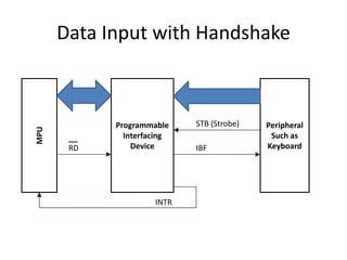
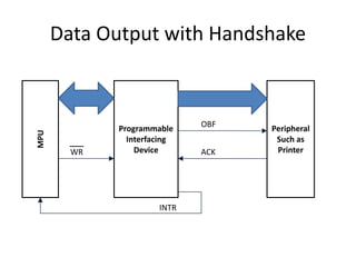
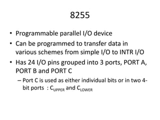

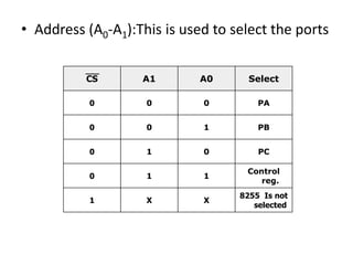
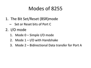
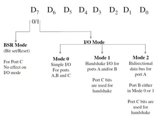
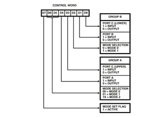
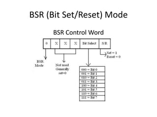
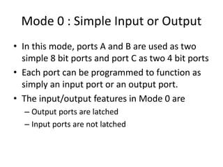
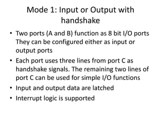
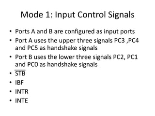
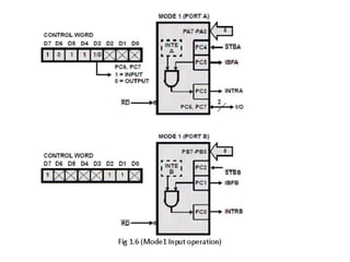
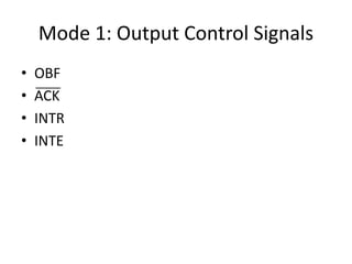
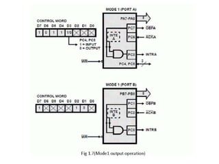
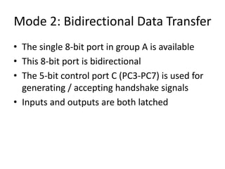
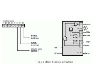

This document discusses programmable peripheral interface devices that use handshake signals for data input and output. It focuses on the 8255 programmable interface, which has 3 ports (A, B, C) that can be programmed for different I/O schemes. Port C can be used as individual bits or two 4-bit ports. The 8255 supports bit set/reset of port C and 3 modes - simple I/O, I/O with handshake, and bidirectional I/O. Modes 1 and 2 use control signals on port C like STB, IBF, ACK for handshake-based input/output with ports A and B.