8086 pin configuration
•Download as PPTX, PDF•
3 likes•1,381 views

Pin Diagram of 8086 simplified This ppt gives you a step-by-step to understand and remember the pin diagram of 8086

More Related Content
What's hot
What's hot (20)
Similar to 8086 pin configuration
Similar to 8086 pin configuration (20)
Recently uploaded
Recently uploaded (20)
8086 pin configuration
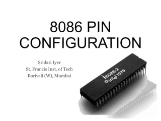
- 1. 8086 PIN CONFIGURATION Sridari Iyer St. Francis Inst. of Tech Borivali (W), Mumbai
- 4. 7/17/20177/17/20177/17/20177/17/2017 8086 1 2 3 4 5 6 7 8 9 10 11 12 13 14 15 16 17 18 19 20 40 39 38 37 36 35 34 33 32 31 30 29 28 27 26 25 24 23 22 21 VccGND GND CLK RESET CLK • Sync events with a 8284 (clock) RESET = 1 (for 4 clk cycles) • Terminate current activity. • Clears all registers and empties the instruction queue
- 5. READY 8086 1 2 3 4 5 6 7 8 9 10 11 12 13 14 15 16 17 18 19 20 40 39 38 37 36 35 34 33 32 31 30 29 28 27 26 25 24 23 22 21 VccGND GND CLK RESET READY = 1 • Data transfer is complete. • Processor is ready for execution READY = 0 • Processor is waiting for some resource.
- 6. Time Multiplexing When the same pin has different functions during different time cycles, that pin is said to be time multiplexed. Aren’t all humans time multiplexed?
- 7. 7/17/2017 AD0 AD1 AD2 AD3 AD4 AD5 AD6 AD7 AD8 AD9 AD10 AD11 AD12 AD13 AD14 8086 1 2 3 4 5 6 7 8 9 10 11 12 13 14 15 16 17 18 19 20 40 39 38 37 36 35 34 33 32 31 30 29 28 27 26 25 24 23 22 21 VccGND GND AD15 CLK RESET READY D0 – D15 16-bit data line A0 – A15 Lower 16 bits of address line ALE = 1 Line carries address ALE = 0 Line carries data ALE
- 8. 7/17/20177/17/2017 8086 1 2 3 4 5 6 7 8 9 10 11 12 13 14 15 16 17 18 19 20 40 39 38 37 36 35 34 33 32 31 30 29 28 27 26 25 24 23 22 21 VccGND GND AD0 AD1 AD2 AD3 AD4 AD5 AD6 AD7 AD8 AD9 AD10 AD11 AD12 AD13 AD14 A19 / S6 A18 / S5 A17 / S4 A16 / S3 AD15 CLK RESET READY A16 – A19 Higher 4 bits of address line S3 – S6 Status Signals
- 9. 7/17/20177/17/2017 8086 1 2 3 4 5 6 7 8 9 10 11 12 13 14 15 16 17 18 19 20 40 39 38 37 36 35 34 33 32 31 30 29 28 27 26 25 24 23 22 21 VccGND GND AD0 AD1 AD2 AD3 AD4 AD5 AD6 AD7 AD8 AD9 AD10 AD11 AD12 AD13 AD14 A19 / S6 A18 / S5 A17 / S4 A16 / S3 AD15 CLK RESET READY S3 S4 Segment 0 0 Extra 0 1 Stack 1 0 Code 1 1 Data S5 indicates interrupt flag is set S6 is 0 when 8086 is BM
- 10. 7/17/20177/17/20177/17/2017 8086 1 2 3 4 5 6 7 8 9 10 11 12 13 14 15 16 17 18 19 20 40 39 38 37 36 35 34 33 32 31 30 29 28 27 26 25 24 23 22 21 VccGND GND AD0 AD1 AD2 AD3 AD4 AD5 AD6 AD7 AD8 AD9 AD10 AD11 AD12 AD13 AD14 A19 / S6 A18 / S5 A17 / S4 A16 / S3 AD15 CLK RESET READY INTR NMI INTR Interrupt Request NMI Non-Maskable Interrupt
- 11. Active High / Active Low? •Describes how a pin is activated. •Active high pins are enabled when set to 1 •Active low pins are enabled when set to 0 •By default all pins are directly connected to the Vcc. •Active low pins are connected via NOT gate •If we do not want certain pins to be active by default, we will reverse their role.
- 12. Why active low pins? Consider a water tank. When tank is filled more than half, assume L = 1 When tank falls to less than half assume L = 0 i.e., L indicates the water level. When should the water pump motor start? When L = 0 Or L = 1 ??
- 13. 7/17/20177/17/20177/17/2017 8086 1 2 3 4 5 6 7 8 9 10 11 12 13 14 15 16 17 18 19 20 40 39 38 37 36 35 34 33 32 31 30 29 28 27 26 25 24 23 22 21 VccGND GND AD0 AD1 AD2 AD3 AD4 AD5 AD6 AD7 AD8 AD9 AD10 AD11 AD12 AD13 AD14 𝐵𝐻𝐸 / S7 AD15 CLK RESET A19 / S6 A18 / S5 A17 / S4 A16 / S3 READY INTR NMI BHE = 0 Enable data on D8 – D15 BHE = 1 Enable data on D0 – D7 S7 reserved for future BHE A0 Access 0 0 16-bit word (D15 – D0) 0 1 Upper byte (D15 – D8) 1 0 Lower byte (D7 – D0) 1 1 Invalid
- 14. 7/17/20177/17/20177/17/20177/17/20177/17/2017 8086 1 2 3 4 5 6 7 8 9 10 11 12 13 14 15 16 17 18 19 20 40 39 38 37 36 35 34 33 32 31 30 29 28 27 26 25 24 23 22 21 VccGND GND AD0 AD1 AD2 AD3 AD4 AD5 AD6 AD7 AD8 AD9 AD10 AD11 AD12 AD13 AD14 𝐵𝐻𝐸/ S7 AD15 CLK RESET A19 / S6 A18 / S5 A17 / S4 A16 / S3 READY 𝑇𝐸𝑆𝑇INTR NMI TEST = 0 Wait instruction TEST = 1 Resume execution
- 15. 7/17/20177/17/20177/17/20177/17/20177/17/20177/17/2017 8086 1 2 3 4 5 6 7 8 9 10 11 12 13 14 15 16 17 18 19 20 40 39 38 37 36 35 34 33 32 31 30 29 28 27 26 25 24 23 22 21 VccGND GND AD0 AD1 AD2 AD3 AD4 AD5 AD6 AD7 AD8 AD9 AD10 AD11 AD12 AD13 AD14 𝐵𝐻𝐸/ S7 AD15 CLK RESET A19 / S6 A18 / S5 A17 / S4 A16 / S3 READY 𝑇𝐸𝑆𝑇 𝑅𝐷 INTR NMI RD = 0 Read RD = 1 No read
- 16. 7/17/20177/17/20177/17/20177/17/20177/17/2017 8086 1 2 3 4 5 6 7 8 9 10 11 12 13 14 15 16 17 18 19 20 40 39 38 37 36 35 34 33 32 31 30 29 28 27 26 25 24 23 22 21 VccGND GND AD0 AD1 AD2 AD3 AD4 AD5 AD6 AD7 AD8 AD9 AD10 AD11 AD12 AD13 AD14 𝐵𝐻𝐸/ S7 AD15 CLK RESET A19 / S6 A18 / S5 A17 / S4 A16 / S3 READY 𝑇𝐸𝑆𝑇 𝑅𝐷 MN / 𝑀𝑋 INTR NMI 0 Max Mode 1 Min Mode
- 17. Modes of Operation Processor needs control over the address, data and control buses to access memory and I/O devices. • Minimum mode – single processor mode • Processor issues control signals • Maximum mode – multi processor mode • The bus controller issues control signals These modes of operations are available only in 8086/88.
- 18. 7/17/20177/17/20177/17/20177/17/20177/17/2017 8086 1 2 3 4 5 6 7 8 9 10 11 12 13 14 15 16 17 18 19 20 40 39 38 37 36 35 34 33 32 31 30 29 28 27 26 25 24 23 22 21 VccGND GND AD0 AD1 AD2 AD3 AD4 AD5 AD6 AD7 AD8 AD9 AD10 AD11 AD12 AD13 AD14 𝐵𝐻𝐸/ S7 AD15 CLK RESET A19 / S6 A18 / S5 A17 / S4 A16 / S3 READY 𝑇𝐸𝑆𝑇 𝑅𝐷 𝑀𝑋 INTR NMI HOLD HLDA 𝑊𝑅 M / 𝐼𝑂 DT / 𝑅 𝐷𝐸𝑁 ALE 𝐼𝑁𝑇𝐴 𝑅𝑄 / GT0 𝑅𝑄 / GT1 LOCK 𝑆 𝑂 𝑆2 QS0 𝑆1 QS1 MN /
- 19. Minimum Mode
- 20. 7/17/20177/17/20177/17/20177/17/20177/17/2017 8086 1 2 3 4 5 6 7 8 9 10 11 12 13 14 15 16 17 18 19 20 40 39 38 37 36 35 34 33 32 31 30 29 28 27 26 25 24 23 22 21 VccGND GND AD0 AD1 AD2 AD3 AD4 AD5 AD6 AD7 AD8 AD9 AD10 AD11 AD12 AD13 AD14 𝐵𝐻𝐸/ S7 AD15 CLK RESET A19 / S6 A18 / S5 A17 / S4 A16 / S3 READY 𝑇𝐸𝑆𝑇 𝑅𝐷 MN / 𝑀𝑋 INTR NMI HOLD HLDA When the DMA controller wants to take control of the data bus, it seeks the permission of the processor by setting HOLD. Processor gives permission by setting HLDA.
- 21. 7/17/20177/17/20177/17/20177/17/20177/17/2017 8086 1 2 3 4 5 6 7 8 9 10 11 12 13 14 15 16 17 18 19 20 40 39 38 37 36 35 34 33 32 31 30 29 28 27 26 25 24 23 22 21 VccGND GND AD0 AD1 AD2 AD3 AD4 AD5 AD6 AD7 AD8 AD9 AD10 AD11 AD12 AD13 AD14 𝐵𝐻𝐸/ S7 AD15 CLK RESET A19 / S6 A18 / S5 A17 / S4 A16 / S3 READY 𝑇𝐸𝑆𝑇 𝑅𝐷 MN / 𝑀𝑋 INTR NMI HOLD HLDA 𝑊𝑅
- 22. 7/17/20177/17/20177/17/20177/17/20177/17/2017 8086 1 2 3 4 5 6 7 8 9 10 11 12 13 14 15 16 17 18 19 20 40 39 38 37 36 35 34 33 32 31 30 29 28 27 26 25 24 23 22 21 VccGND GND AD0 AD1 AD2 AD3 AD4 AD5 AD6 AD7 AD8 AD9 AD10 AD11 AD12 AD13 AD14 𝐵𝐻𝐸/ S7 AD15 CLK RESET A19 / S6 A18 / S5 A17 / S4 A16 / S3 READY 𝑇𝐸𝑆𝑇 𝑅𝐷 MN / 𝑀𝑋 INTR NMI HOLD HLDA 𝑊𝑅 M / 𝐼𝑂
- 23. 7/17/20177/17/20177/17/20177/17/20177/17/2017 8086 1 2 3 4 5 6 7 8 9 10 11 12 13 14 15 16 17 18 19 20 40 39 38 37 36 35 34 33 32 31 30 29 28 27 26 25 24 23 22 21 VccGND GND AD0 AD1 AD2 AD3 AD4 AD5 AD6 AD7 AD8 AD9 AD10 AD11 AD12 AD13 AD14 𝐵𝐻𝐸/ S7 AD15 CLK RESET A19 / S6 A18 / S5 A17 / S4 A16 / S3 READY 𝑇𝐸𝑆𝑇 𝑅𝐷 MN / 𝑀𝑋 INTR NMI HOLD HLDA 𝑊𝑅 M / 𝐼𝑂 DT / 𝑅 0 Receive 1 Transmit
- 24. 7/17/20177/17/20177/17/20177/17/20177/17/2017 8086 1 2 3 4 5 6 7 8 9 10 11 12 13 14 15 16 17 18 19 20 40 39 38 37 36 35 34 33 32 31 30 29 28 27 26 25 24 23 22 21 VccGND GND AD0 AD1 AD2 AD3 AD4 AD5 AD6 AD7 AD8 AD9 AD10 AD11 AD12 AD13 AD14 𝐵𝐻𝐸/ S7 AD15 CLK RESET A19 / S6 A18 / S5 A17 / S4 A16 / S3 READY 𝑇𝐸𝑆𝑇 𝑅𝐷 MN / 𝑀𝑋 INTR NMI HOLD HLDA 𝑊𝑅 M / 𝐼𝑂 DT / 𝑅 𝐷𝐸𝑁 Enables the data on the external buffers
- 25. 7/17/20177/17/20177/17/20177/17/20177/17/2017 8086 1 2 3 4 5 6 7 8 9 10 11 12 13 14 15 16 17 18 19 20 40 39 38 37 36 35 34 33 32 31 30 29 28 27 26 25 24 23 22 21 VccGND GND AD0 AD1 AD2 AD3 AD4 AD5 AD6 AD7 AD8 AD9 AD10 AD11 AD12 AD13 AD14 𝐵𝐻𝐸/ S7 AD15 CLK RESET A19 / S6 A18 / S5 A17 / S4 A16 / S3 READY 𝑇𝐸𝑆𝑇 𝑅𝐷 MN / 𝑀𝑋 INTR NMI HOLD HLDA 𝑊𝑅 M / 𝐼𝑂 DT / 𝑅 𝐷𝐸𝑁 ALE ALE=0 Carry Data ALE =1 Carry Address
- 26. 7/17/20177/17/20177/17/20177/17/20177/17/2017 8086 1 2 3 4 5 6 7 8 9 10 11 12 13 14 15 16 17 18 19 20 40 39 38 37 36 35 34 33 32 31 30 29 28 27 26 25 24 23 22 21 VccGND GND AD0 AD1 AD2 AD3 AD4 AD5 AD6 AD7 AD8 AD9 AD10 AD11 AD12 AD13 AD14 𝐵𝐻𝐸/ S7 AD15 CLK RESET A19 / S6 A18 / S5 A17 / S4 A16 / S3 READY 𝑇𝐸𝑆𝑇 𝑅𝐷 MN / 𝑀𝑋 INTR NMI HOLD HLDA 𝑊𝑅 M / 𝐼𝑂 DT / 𝑅 𝐷𝐸𝑁 ALE 𝐼𝑁𝑇𝐴
- 27. Maximum Mode
- 28. 7/17/20177/17/20177/17/20177/17/20177/17/2017 8086 1 2 3 4 5 6 7 8 9 10 11 12 13 14 15 16 17 18 19 20 40 39 38 37 36 35 34 33 32 31 30 29 28 27 26 25 24 23 22 21 VccGND GND AD0 AD1 AD2 AD3 AD4 AD5 AD6 AD7 AD8 AD9 AD10 AD11 AD12 AD13 AD14 𝐵𝐻𝐸/ S7 AD15 CLK RESET A19 / S6 A18 / S5 A17 / S4 A16 / S3 READY 𝑇𝐸𝑆𝑇 𝑅𝐷 MN / 𝑀𝑋 INTR NMI 𝑆 𝑂 𝑆2 𝑆1 S0 S1 S2 Status 0 0 0 Interrupt Ack 0 0 1 I/O Read 0 1 0 I / O Write 0 1 1 HALT 1 0 0 Instruction Fetch 1 0 1 Memory Read 1 1 0 Memory Write 1 1 1 Inactive
- 29. 7/17/20177/17/20177/17/20177/17/20177/17/2017 8086 1 2 3 4 5 6 7 8 9 10 11 12 13 14 15 16 17 18 19 20 40 39 38 37 36 35 34 33 32 31 30 29 28 27 26 25 24 23 22 21 VccGND GND AD0 AD1 AD2 AD3 AD4 AD5 AD6 AD7 AD8 AD9 AD10 AD11 AD12 AD13 AD14 𝐵𝐻𝐸/ S7 AD15 CLK RESET A19 / S6 A18 / S5 A17 / S4 A16 / S3 READY 𝑇𝐸𝑆𝑇 𝑅𝐷 MN / 𝑀𝑋 INTR NMI 𝑆 𝑂 𝑆2 𝑆1 QS0 QS1 Instruction Queue Status pins QS0 QS1 Status 0 0 No Operation 0 1 First byte of opcode from Queue 1 0 Empty Queue 1 1 Subsequent bytes of opcode
- 30. 7/17/20177/17/20177/17/20177/17/20177/17/2017 8086 1 2 3 4 5 6 7 8 9 10 11 12 13 14 15 16 17 18 19 20 40 39 38 37 36 35 34 33 32 31 30 29 28 27 26 25 24 23 22 21 VccGND GND AD0 AD1 AD2 AD3 AD4 AD5 AD6 AD7 AD8 AD9 AD10 AD11 AD12 AD13 AD14 𝐵𝐻𝐸/ S7 AD15 CLK RESET A19 / S6 A18 / S5 A17 / S4 A16 / S3 READY 𝑇𝐸𝑆𝑇 𝑅𝐷 MN / 𝑀𝑋 INTR NMI 𝑅𝑄 / GT0 𝑅𝑄 / GT1 𝑆 𝑂 𝑆2 𝑆1 QS0 QS1 Signals for resource sharing between processors . RQ – Request GT - Grant
- 31. 7/17/20177/17/20177/17/20177/17/20177/17/2017 8086 1 2 3 4 5 6 7 8 9 10 11 12 13 14 15 16 17 18 19 20 40 39 38 37 36 35 34 33 32 31 30 29 28 27 26 25 24 23 22 21 VccGND GND AD0 AD1 AD2 AD3 AD4 AD5 AD6 AD7 AD8 AD9 AD10 AD11 AD12 AD13 AD14 𝐵𝐻𝐸/ S7 AD15 CLK RESET A19 / S6 A18 / S5 A17 / S4 A16 / S3 READY 𝑇𝐸𝑆𝑇 𝑅𝐷 MN / 𝑀𝑋 INTR NMI 𝑅𝑄 / GT0 𝑅𝑄 / GT1 LOCK 𝑆 𝑂 𝑆2 𝑆1 QS0 QS1 Lock the peripherals