This document summarizes guidelines for determining short circuit current rating (SCCR) for electrical equipment. It discusses:
- Upcoming 2017 NEC changes that will require marking or documenting the available fault current where equipment is installed.
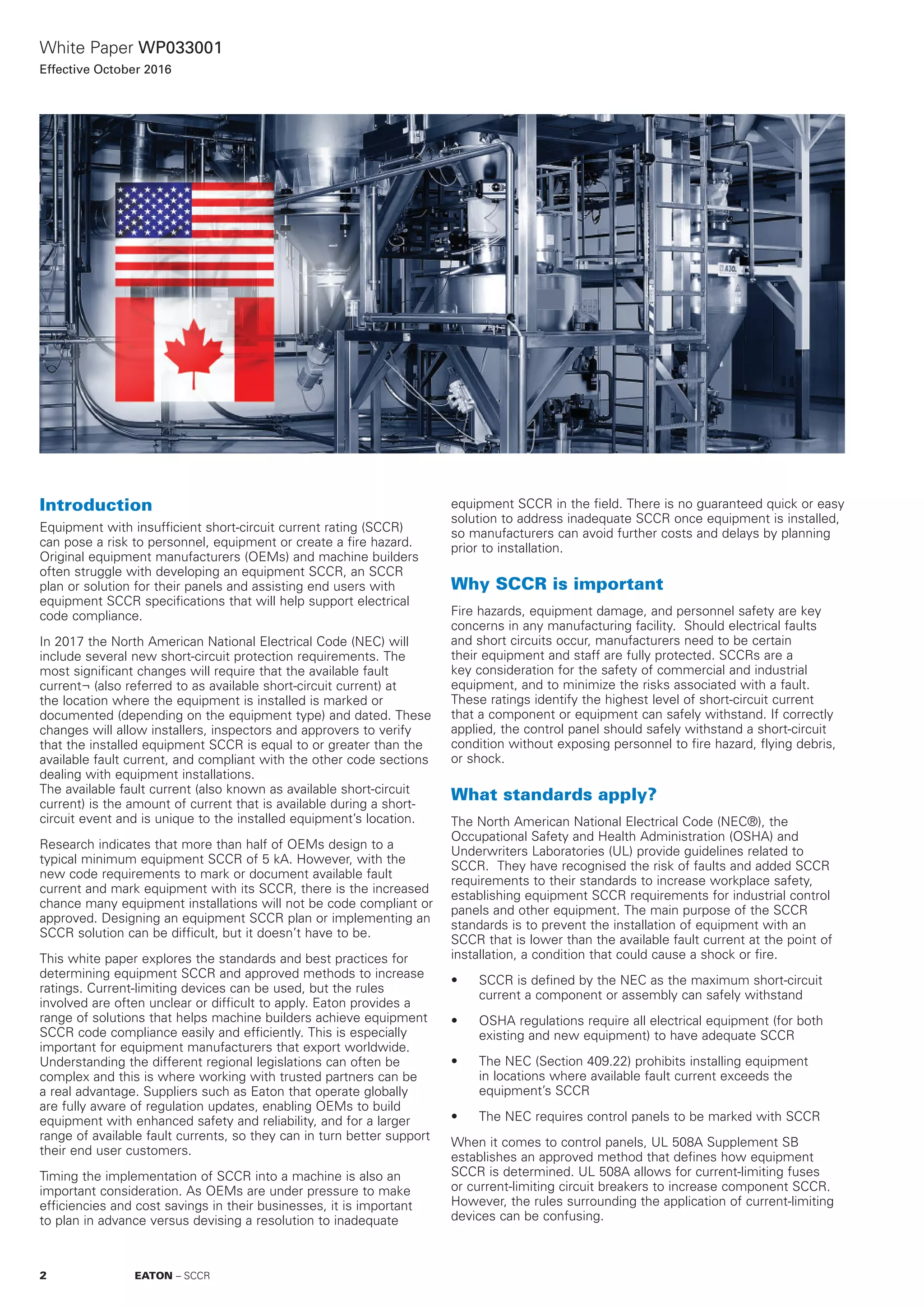
- Methods for determining equipment SCCR, including considering the ratings of components, overcurrent devices, and whether current-limiting devices can increase component ratings.
- Basic guidelines for using current-limiting devices to increase SCCR, such as only being able to raise branch component SCCR, not feeder components or overcurrent device ratings.
- A 4-step process to calculate equipment SCCR by determining component and overcurrent device ratings and identifying the lowest rating.

![White Paper WP033001
Effective October 2016
2
6
4
20
10
8
100
60
200
40
80
1
65 108 15 2041 32 100 15030
2xIcc
[kA]
D
Î
5040 8060
NZMH2-A(AF)...-NA
480 V
600 V
240 V
[kA]Icc rms
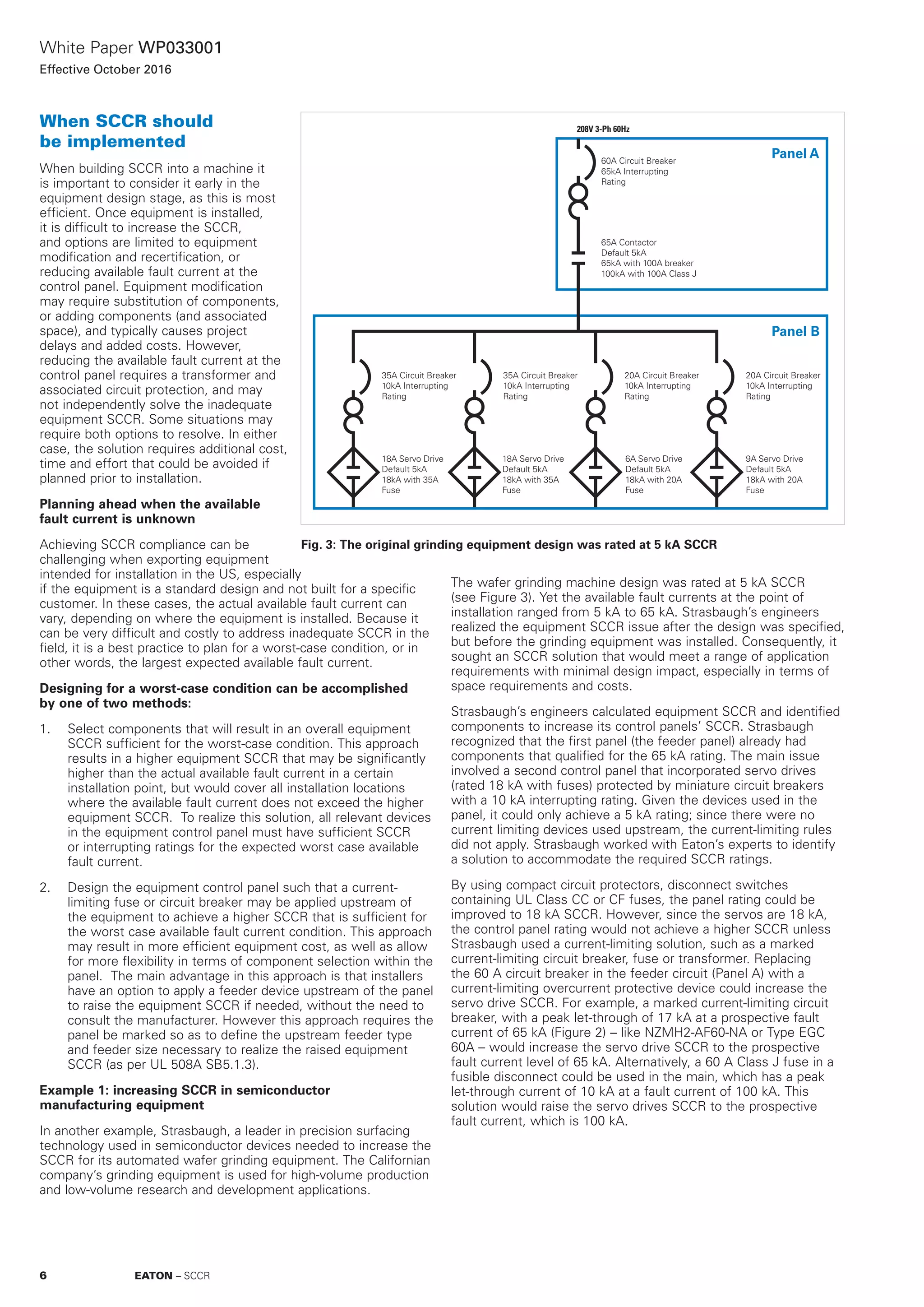
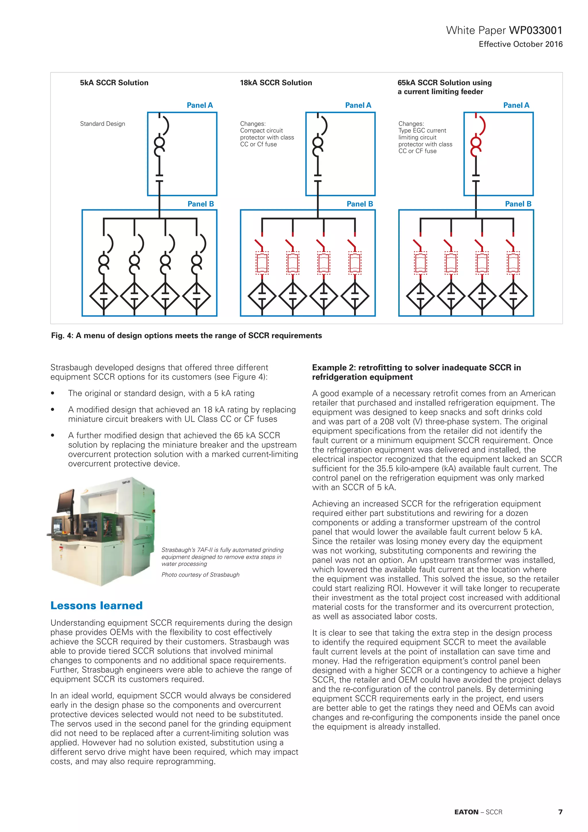
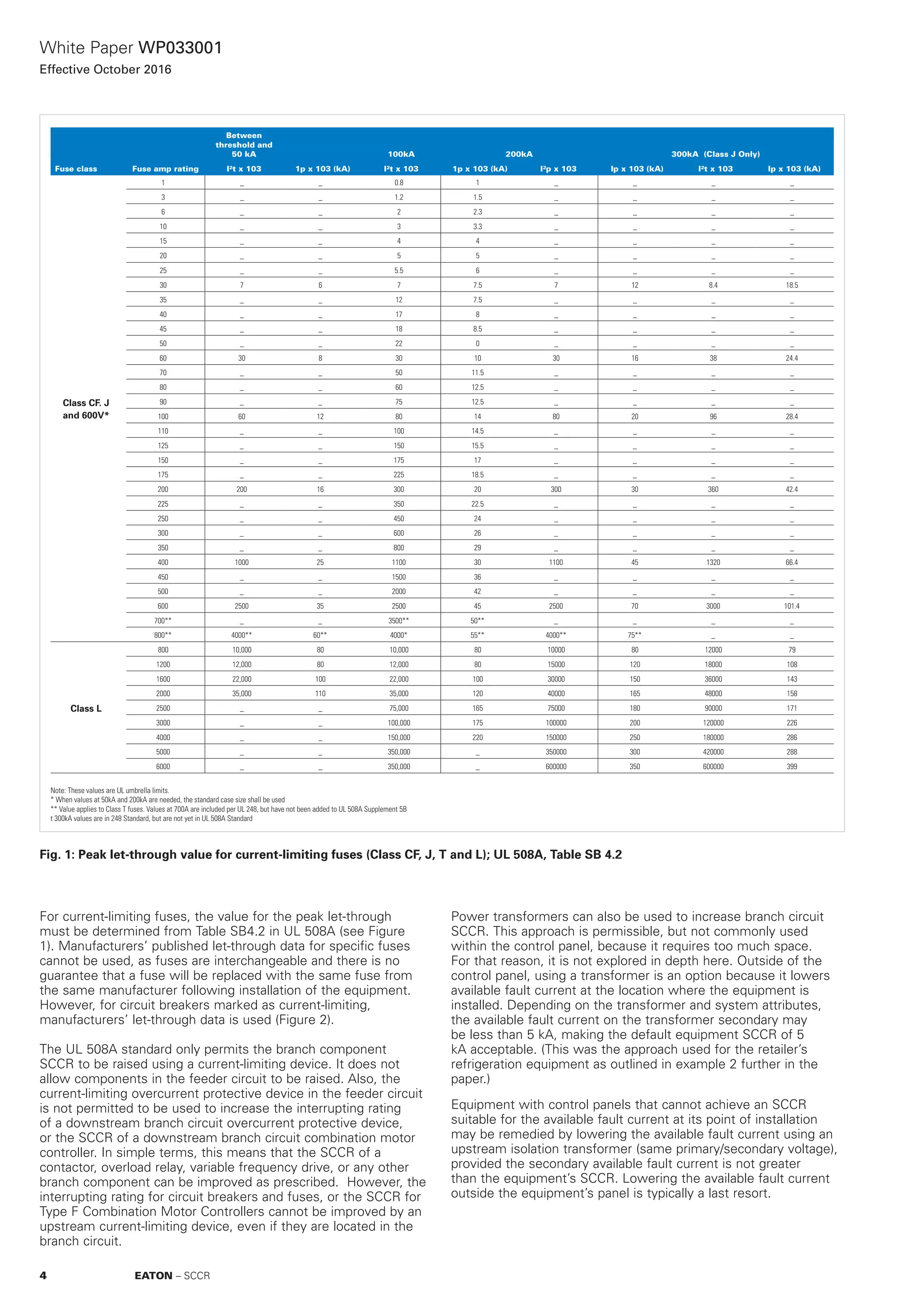
Fig. 2: Manufacturer let-through charts for
current-limiting breakers; The example
above is for Eaton’s Moeller Series NZM
breaker, type NZMH2-VE250-NA, molded
case circuit breaker - 240V, 480V, 600V.
Basic guidelines
Marked current-limiting fuses or current-limiting circuit breakers cannot be used to increase component SCCR or the interrupting rating of an overcurrent
protective device in the feeder circuit
Branch circuit component SCCR can be raised using a current-limiting overcurrent protective device in the feeder circuit under specified conditions
Marked current-limiting fuses or circuit breakers cannot be used to increase the interrupting rating of a branch circuit overcurrent protective device; only
component SCCRs are affected
Branch and feeder circuit overcurrent protective devices must have sufficient interupting rating for the available fault current
Marked current-limiting devices or fuses and circuit breakers cannot be used to increase the SCCR of a branch circuit combination motor controller
Combination motor controllers must have sufficient SCCR for the available fault current
Marked current-limiting fuses and circuit breakers are permitted to be field installed upstream of the control panel. However, the higher resulting SCCR and
the specific current-limiting overcurrent protective device must be marked on the panel
4 steps to calculate equipment SCCR
Determine SCCR of components incorporated in the feeder and branch circuits
Determine the potential of current-limiting devices in the feeder circuit to increase the SCCR of branch circuit components
Identify interrupting ratings of all overcurrent protective devices in the feeder and branch circuits, as well as on the primary of control transformers and
power supplies
The equipment SCCR is the lowest value of the component SCCRs, raised component SCCRs, or interrupting ratings of the overcurrent protective devices.
5EATON – SCCR](https://image.slidesharecdn.com/76d7e191-801e-4032-8c0f-2e0e374a94fcshortcircuitcurrentratingwp033001en-170527193416/75/76d7e191-801e-4032-8c0f-2e0e374a94fc-short-circuit_current_rating_wp033001_en-5-2048.jpg)