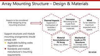
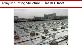
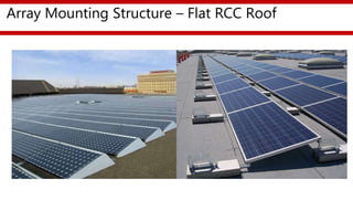
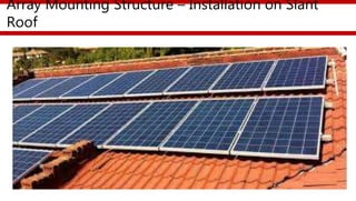
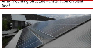
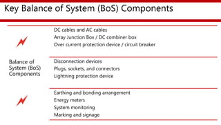
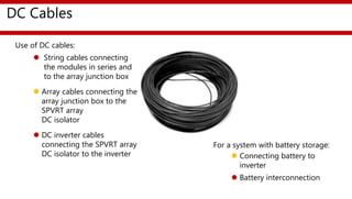
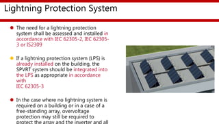
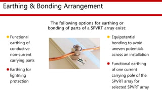
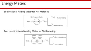
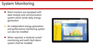
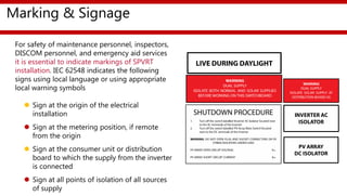
Partnership To Advance Clean Energy-Deployment (PACE-D)
Technical Assistance Program
Presented by
USAID PACE-D TA Program
Apr-18
Solar PV Rooftop Training Program For Entrepreneurs
Session:
Balance of System (BoS) Components
Contents
Array mounting structure
Key Balance of System (BoS) components
DC cables and AC cables
Array junction box / DC combiner box
Contents
Safety and protection devices
Energy meters
System Monitoring
Marking and Signage
Array Mounting Structure – Design & Materials
Thermal Aspects
Expansion /
Contraction of
modules /
Structure
Mechanical
Loads on PV
Structures
To comply with
related standards
Wind
To be rated for
maximum
expected wind
speeds
Material
Accumulation on
PV Array
Snow, ice, others
Corrosion
Mounting to be
made from
corrosion resistant
materials
Support structures and module
mounting arrangements should
comply with
 Applicable building codes
regulations and
 Standards and module
manufacturer’s mounting
requirements
Aspects to be considered
while designing array
mounting structure
IEC 62548
Array Mounting Structure – Flat RCC Roof
Array Mounting Structure – Installation on Slant
Roof
Array Mounting Structure – Installation on Slant
Roof
KEY BALANCE OF SYSTEM (BOS) COMPONENTS
Key Balance of System (BoS) Components
PV Modules
Mounting
frame
Junction Box
DC Cabling
Solar Array Isolator
Inverter AC Cabling
Main Switch
Solar Supply
Meter
Switchboard
Power Grid
Key Balance of System (BoS) Components
Balance of
System (BoS)
Components
DC cables and AC cables
Array Junction Box / DC combiner box
Over current protection device / circuit breaker
Disconnection devices
Plugs, sockets, and connectors
Lightning protection device
Earthing and bonding arrangement
Energy meters
System monitoring
Marking and signage
DC Cables
Use of DC cables:
 String cables connecting
the modules in series and
to the array junction box
 Array cables connecting the
array junction box to the
SPVRT array
DC isolator
 DC inverter cables
connecting the SPVRT array
DC isolator to the inverter
For a system with battery storage:
 Connecting battery to
inverter
 Battery interconnection
Tools & Accessories for Wire Connection
Array Junction Box / DC Combiner Box
 SPVRT strings are
connected in a junction
/ combiner box which
also contains
overcurrent protection
devices and / or switch-
disconnectors
 SPVRT array and SPVRT
string combiner boxes
shall be at least IP 54
compliant in accordance
with IEC 60529, and
shall be UV resistant.
 Shall be capable of being
reached for inspection,
maintenance or repairs
 There should be segregation
between positive and
negative conductors within
combiner boxes to minimize
the risks of DC arcs
Over Current Protection Device / Circuit Breakers
 Requirement of OCPD in SPVRT array
shall be determined as per section 6.3 of
IEC62548
 String OCP shall be located at the string
in the sub-array or array cables in the
string combiner box
 Sub-array OCPD shall be installed in the
sub-array cables in the array combiner
box
 Array OCPD shall be installed at the
array cables in the application circuit or
the inverter
 OCPD shall be certified to either IEC
60898-2 or IEC 60947-2
Disconnection Devices
 Circuit Breakers used for overcurrent
protection in SPVRT array shall be
 Certified to IEC 60898 or IEC
60947-2 (IS 13947)
 Not polarity sensitive
 Rated to interrupt full load and
prospective fault current
 Rated for overcurrent as per IEC
62548 section 6.3.5.
 All circuit breakers used, need to be
rated for DC
According to CEA (Technical Standards for Connectivity of the Distributed Generation
Resources) Regulations, 2013, a manual isolating switch shall be installed between the
inverter and the electricity grid. It is recommended to place that on the inverter side of the
PV metering device in the switchboard.
 It must Interrupt the active conductor
 Be capable of being locked in open position
 Be located at a height of at least 2.44m above the ground level
 May not be rated for load break nor may have feature of over-current protection
 Comply with all other specifications as per CEA Regulations
Disconnection Devices
Plugs, Sockets & Connectors
 Be rated for DC use
 Have a voltage and current rating as per section 7 of IEC-62548
 Require a deliberate force to disconnect
 If accessible by untrained people then shall be of the locking type where two
independent actions are required to disconnect
 Be rated for outdoor use, be UV-resistant and be of an IP rating suitable for the
location
 Plugs and socket outlets normally used for the connection of household
equipment to low voltage AC power shall not be used in PV arrays
Lightning Protection System
 The need for a lightning protection
system shall be assessed and installed in
accordance with IEC 62305-2, IEC 62305-
3 or IS2309
 If a lightning protection system (LPS) is
already installed on the building, the
SPVRT system should be integrated into
the LPS as appropriate in accordance
with
IEC 62305-3
 In the case where no lightning system is
required on a building or in a case of a
free-standing array, overvoltage
protection may still be required to
protect the array and the inverter and all
Earthing & Bonding Arrangement
Functional
earthing of
conductive
non-current
carrying parts
Earthing for
lightning
protection
 Equipotential
bonding to avoid
uneven potentials
across an installation
 Functional earthing
of one current
carrying pole of the
SPVRT array for
selected SPVRT array
The following options for earthing or
bonding of parts of a SPVRT array exist:
Energy Meters
Bi-directional Analog Meter for Net Metering
Two Uni-directional Analog Meter for Net Metering
System Monitoring
 Most inverters are equipped with
data module and communication
system which sends daily energy
generation
 An independent energy generation
and performance monitoring system
can also be installed
 When required, a residual current
monitoring and earth fault alarm
system shall be installed
Marking & Signage
For safety of maintenance personnel, inspectors,
DISCOM personnel, and emergency aid services
it is essential to indicate markings of SPVRT
installation. IEC 62548 indicates the following
signs using local language or using appropriate
local warning symbols
 Sign at the origin of the electrical
installation
 Sign at the metering position, if remote
from the origin
 Sign at the consumer unit or distribution
board to which the supply from the inverter
is connected
 Sign at all points of isolation of all sources
of supply
 What are the major components of a SPVRT system?
 What are the balance of system (BoS) components of a SPVRT system?
 How do you qualify PV modules for grid-connected SPVRT system?
 How is a grid connected inverter different from a UPS inverter?
 How do you identify an isolated or non-isolated grid-connected inverter?
 What are the advantages and disadvantages of micro inverter?
 Why does the SPVRT system require earthing?
 Why should marking and signage be installed in an SPVRT system?
Recapturing the Session
25
Anurag Mishra
Senior Clean Energy Specialist
USAID/India
Email: amishra@usaid.gov
Disclaimer:
This training material is made possible by the support of the American
People through the United States Agency for International
Development (USAID). The contents of this material are the sole
responsibility of Nexant, Inc. and do not necessarily reflect the views of
USAID or the United States Government. This material was prepared
under Contract Number AID-386-C-12-00001.

Session 06 balance of system components

  • 1.
    Partnership To AdvanceClean Energy-Deployment (PACE-D) Technical Assistance Program Presented by USAID PACE-D TA Program Apr-18 Solar PV Rooftop Training Program For Entrepreneurs Session: Balance of System (BoS) Components
  • 2.
    Contents Array mounting structure KeyBalance of System (BoS) components DC cables and AC cables Array junction box / DC combiner box
  • 3.
    Contents Safety and protectiondevices Energy meters System Monitoring Marking and Signage
  • 4.
    Array Mounting Structure– Design & Materials Thermal Aspects Expansion / Contraction of modules / Structure Mechanical Loads on PV Structures To comply with related standards Wind To be rated for maximum expected wind speeds Material Accumulation on PV Array Snow, ice, others Corrosion Mounting to be made from corrosion resistant materials Support structures and module mounting arrangements should comply with  Applicable building codes regulations and  Standards and module manufacturer’s mounting requirements Aspects to be considered while designing array mounting structure IEC 62548
  • 5.
    Array Mounting Structure– Flat RCC Roof
  • 6.
    Array Mounting Structure– Flat RCC Roof
  • 7.
    Array Mounting Structure– Installation on Slant Roof
  • 8.
    Array Mounting Structure– Installation on Slant Roof
  • 9.
    KEY BALANCE OFSYSTEM (BOS) COMPONENTS
  • 10.
    Key Balance ofSystem (BoS) Components PV Modules Mounting frame Junction Box DC Cabling Solar Array Isolator Inverter AC Cabling Main Switch Solar Supply Meter Switchboard Power Grid
  • 11.
    Key Balance ofSystem (BoS) Components Balance of System (BoS) Components DC cables and AC cables Array Junction Box / DC combiner box Over current protection device / circuit breaker Disconnection devices Plugs, sockets, and connectors Lightning protection device Earthing and bonding arrangement Energy meters System monitoring Marking and signage
  • 12.
    DC Cables Use ofDC cables:  String cables connecting the modules in series and to the array junction box  Array cables connecting the array junction box to the SPVRT array DC isolator  DC inverter cables connecting the SPVRT array DC isolator to the inverter For a system with battery storage:  Connecting battery to inverter  Battery interconnection
  • 13.
    Tools & Accessoriesfor Wire Connection
  • 14.
    Array Junction Box/ DC Combiner Box  SPVRT strings are connected in a junction / combiner box which also contains overcurrent protection devices and / or switch- disconnectors  SPVRT array and SPVRT string combiner boxes shall be at least IP 54 compliant in accordance with IEC 60529, and shall be UV resistant.  Shall be capable of being reached for inspection, maintenance or repairs  There should be segregation between positive and negative conductors within combiner boxes to minimize the risks of DC arcs
  • 15.
    Over Current ProtectionDevice / Circuit Breakers  Requirement of OCPD in SPVRT array shall be determined as per section 6.3 of IEC62548  String OCP shall be located at the string in the sub-array or array cables in the string combiner box  Sub-array OCPD shall be installed in the sub-array cables in the array combiner box  Array OCPD shall be installed at the array cables in the application circuit or the inverter  OCPD shall be certified to either IEC 60898-2 or IEC 60947-2
  • 16.
    Disconnection Devices  CircuitBreakers used for overcurrent protection in SPVRT array shall be  Certified to IEC 60898 or IEC 60947-2 (IS 13947)  Not polarity sensitive  Rated to interrupt full load and prospective fault current  Rated for overcurrent as per IEC 62548 section 6.3.5.  All circuit breakers used, need to be rated for DC
  • 17.
    According to CEA(Technical Standards for Connectivity of the Distributed Generation Resources) Regulations, 2013, a manual isolating switch shall be installed between the inverter and the electricity grid. It is recommended to place that on the inverter side of the PV metering device in the switchboard.  It must Interrupt the active conductor  Be capable of being locked in open position  Be located at a height of at least 2.44m above the ground level  May not be rated for load break nor may have feature of over-current protection  Comply with all other specifications as per CEA Regulations Disconnection Devices
  • 18.
    Plugs, Sockets &Connectors  Be rated for DC use  Have a voltage and current rating as per section 7 of IEC-62548  Require a deliberate force to disconnect  If accessible by untrained people then shall be of the locking type where two independent actions are required to disconnect  Be rated for outdoor use, be UV-resistant and be of an IP rating suitable for the location  Plugs and socket outlets normally used for the connection of household equipment to low voltage AC power shall not be used in PV arrays
  • 19.
    Lightning Protection System The need for a lightning protection system shall be assessed and installed in accordance with IEC 62305-2, IEC 62305- 3 or IS2309  If a lightning protection system (LPS) is already installed on the building, the SPVRT system should be integrated into the LPS as appropriate in accordance with IEC 62305-3  In the case where no lightning system is required on a building or in a case of a free-standing array, overvoltage protection may still be required to protect the array and the inverter and all
  • 20.
    Earthing & BondingArrangement Functional earthing of conductive non-current carrying parts Earthing for lightning protection  Equipotential bonding to avoid uneven potentials across an installation  Functional earthing of one current carrying pole of the SPVRT array for selected SPVRT array The following options for earthing or bonding of parts of a SPVRT array exist:
  • 21.
    Energy Meters Bi-directional AnalogMeter for Net Metering Two Uni-directional Analog Meter for Net Metering
  • 22.
    System Monitoring  Mostinverters are equipped with data module and communication system which sends daily energy generation  An independent energy generation and performance monitoring system can also be installed  When required, a residual current monitoring and earth fault alarm system shall be installed
  • 23.
    Marking & Signage Forsafety of maintenance personnel, inspectors, DISCOM personnel, and emergency aid services it is essential to indicate markings of SPVRT installation. IEC 62548 indicates the following signs using local language or using appropriate local warning symbols  Sign at the origin of the electrical installation  Sign at the metering position, if remote from the origin  Sign at the consumer unit or distribution board to which the supply from the inverter is connected  Sign at all points of isolation of all sources of supply
  • 24.
     What arethe major components of a SPVRT system?  What are the balance of system (BoS) components of a SPVRT system?  How do you qualify PV modules for grid-connected SPVRT system?  How is a grid connected inverter different from a UPS inverter?  How do you identify an isolated or non-isolated grid-connected inverter?  What are the advantages and disadvantages of micro inverter?  Why does the SPVRT system require earthing?  Why should marking and signage be installed in an SPVRT system? Recapturing the Session
  • 25.
    25 Anurag Mishra Senior CleanEnergy Specialist USAID/India Email: amishra@usaid.gov Disclaimer: This training material is made possible by the support of the American People through the United States Agency for International Development (USAID). The contents of this material are the sole responsibility of Nexant, Inc. and do not necessarily reflect the views of USAID or the United States Government. This material was prepared under Contract Number AID-386-C-12-00001.

Editor's Notes

  • #13 Note to presenter: 1. Get familiar with the specified section of IEC 62548