Downloaded 280 times


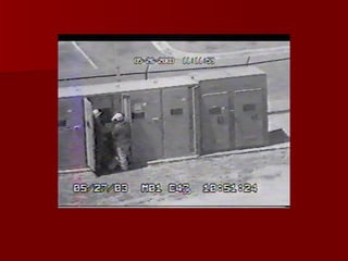
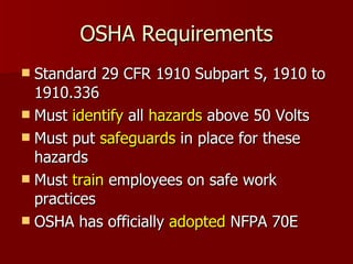
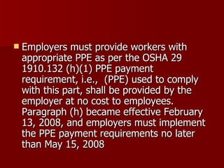
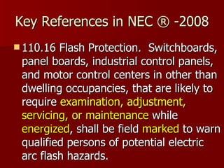
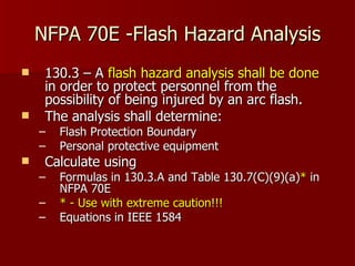
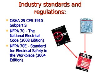
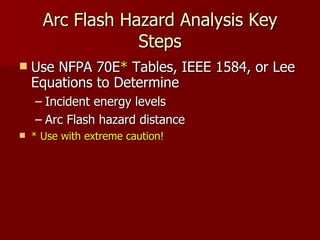
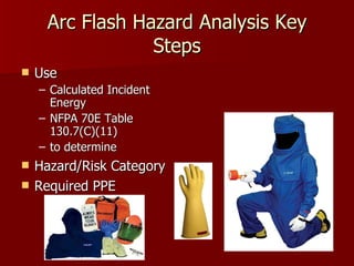
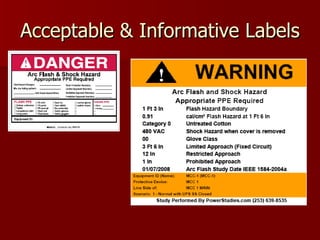
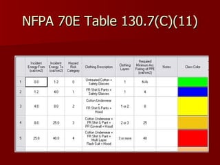
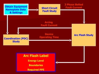
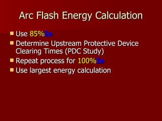
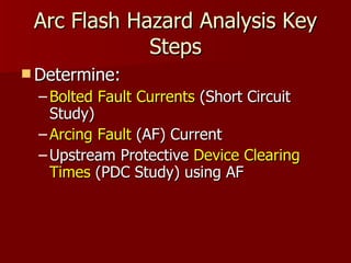
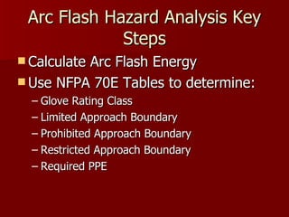
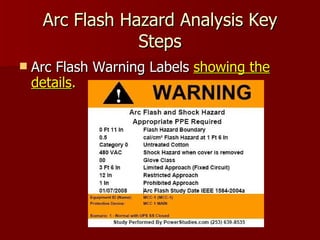

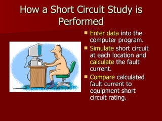
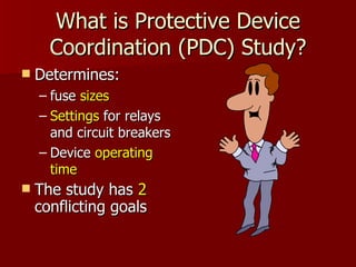
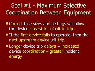


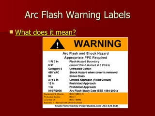


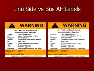


This document discusses arc flash hazard calculations and their importance for electrical safety. It outlines OSHA and NFPA regulations requiring employers to identify electrical hazards and protect workers through appropriate personal protective equipment. Key steps in performing an arc flash hazard analysis include short circuit, protective device coordination, and arc flash studies to determine incident energy levels and necessary PPE based on NFPA tables. Warning labels communicating these hazards must be applied to electrical equipment.


